WO2017142029A1 - ユーザ端末、無線基地局及び無線通信方法 - Google Patents
ユーザ端末、無線基地局及び無線通信方法 Download PDFInfo
- Publication number
- WO2017142029A1 WO2017142029A1 PCT/JP2017/005748 JP2017005748W WO2017142029A1 WO 2017142029 A1 WO2017142029 A1 WO 2017142029A1 JP 2017005748 W JP2017005748 W JP 2017005748W WO 2017142029 A1 WO2017142029 A1 WO 2017142029A1
- Authority
- WO
- WIPO (PCT)
- Prior art keywords
- tti
- user terminal
- transmission
- shared channel
- uplink shared
- Prior art date
- Legal status (The legal status is an assumption and is not a legal conclusion. Google has not performed a legal analysis and makes no representation as to the accuracy of the status listed.)
- Ceased
Links
Images


Classifications
-
- H—ELECTRICITY
- H04—ELECTRIC COMMUNICATION TECHNIQUE
- H04W—WIRELESS COMMUNICATION NETWORKS
- H04W52/00—Power management, e.g. Transmission Power Control [TPC] or power classes
- H04W52/04—Transmission power control [TPC]
- H04W52/06—TPC algorithms
- H04W52/14—Separate analysis of uplink or downlink
- H04W52/146—Uplink power control
-
- H—ELECTRICITY
- H04—ELECTRIC COMMUNICATION TECHNIQUE
- H04W—WIRELESS COMMUNICATION NETWORKS
- H04W52/00—Power management, e.g. Transmission Power Control [TPC] or power classes
- H04W52/04—Transmission power control [TPC]
- H04W52/18—TPC being performed according to specific parameters
- H04W52/22—TPC being performed according to specific parameters taking into account previous information or commands
- H04W52/221—TPC being performed according to specific parameters taking into account previous information or commands using past power control commands
-
- H—ELECTRICITY
- H04—ELECTRIC COMMUNICATION TECHNIQUE
- H04W—WIRELESS COMMUNICATION NETWORKS
- H04W52/00—Power management, e.g. Transmission Power Control [TPC] or power classes
- H04W52/04—Transmission power control [TPC]
- H04W52/30—Transmission power control [TPC] using constraints in the total amount of available transmission power
- H04W52/36—Transmission power control [TPC] using constraints in the total amount of available transmission power with a discrete range or set of values, e.g. step size, ramping or offsets
- H04W52/367—Power values between minimum and maximum limits, e.g. dynamic range
-
- H—ELECTRICITY
- H04—ELECTRIC COMMUNICATION TECHNIQUE
- H04W—WIRELESS COMMUNICATION NETWORKS
- H04W52/00—Power management, e.g. Transmission Power Control [TPC] or power classes
- H04W52/04—Transmission power control [TPC]
- H04W52/30—Transmission power control [TPC] using constraints in the total amount of available transmission power
- H04W52/34—TPC management, i.e. sharing limited amount of power among users or channels or data types, e.g. cell loading
Definitions
- the present invention relates to a user terminal, a radio base station, and a radio communication method in a next-generation mobile communication system.
- LTE Long Term Evolution
- LTE-A also referred to as LTE Advanced, LTE Rel. 10, 11 or 12
- LTE also referred to as LTE Rel. 8 or 9
- Successor systems for example, FRA (Future Radio Access), 5G (5th generation mobile communication system), LTE Rel.13, Rel.14, etc.
- FRA Full Radio Access
- 5G 5th generation mobile communication system
- LTE Rel.13, Rel.14, etc. are also being studied.
- CA Carrier Aggregation
- CC Component Carrier
- UE User Equipment
- DC Dual Connectivity
- CG Cell Group
- CC Cell Center
- frequency division duplex in which downlink (DL) transmission and uplink (UL: Uplink) transmission are performed in different frequency bands, and DL transmission and UL transmission are in the same frequency band.
- Time Division Duplex which is performed by switching over time, is introduced.
- a transmission time interval (TTI) applied to DL transmission and UL transmission between the radio base station and the user terminal is set to 1 ms and controlled.
- the TTI in the existing system (LTE Rel. 8-12) is also called a subframe, a subframe length, or the like.
- E-UTRA Evolved Universal Terrestrial Radio Access
- E-UTRAN Evolved Universal Terrestrial Radio Access Network
- TTI shortening TTI shortening
- the present invention has been made in view of the above points, and provides a user terminal, a radio base station, and a radio communication method capable of appropriately performing communication even when a plurality of TTIs having different time lengths are mixed.
- One purpose is to provide.
- One aspect of the user terminal is a transmitter that transmits an uplink shared channel in a first transmission time interval (TTI) and / or a second TTI configured with a smaller number of symbols than the first TTI. And a control unit that controls transmission power of the uplink shared channel, and the control unit transmits the transmission based on an individual parameter that is individually set according to a TTI length for transmitting the uplink shared channel. It is characterized by controlling electric power.
- TTI transmission time interval
- a control unit that controls transmission power of the uplink shared channel, and the control unit transmits the transmission based on an individual parameter that is individually set according to a TTI length for transmitting the uplink shared channel. It is characterized by controlling electric power.
- communication can be performed appropriately even when a plurality of TTIs having different time lengths are mixed.
- FIGS. 4A and 4B are diagrams illustrating multiplexing examples of DMRSs of a plurality of shortened TTIs. It is explanatory drawing of fractional TPC. It is a figure which shows the example of control of the transmission power of PUSCH which concerns on this Embodiment.
- 7A and 7B are diagrams illustrating an example of calculating the cumulative value of the TPC command according to the present embodiment.
- FIG. 1 is a diagram illustrating an example of a TTI (normal TTI) in an existing system (LTE Rel. 8-12). As shown in FIG. 1, the normal TTI has a time length of 1 ms. A normal TTI is also called a subframe and is composed of two time slots. In the existing system, the normal TTI is a transmission time unit of one channel-coded data packet, and is a processing unit such as scheduling and link adaptation.
- the normal TTI is configured to include 14 OFDM (Orthogonal Frequency Division Multiplexing) symbols (7 OFDM symbols per slot).
- Each OFDM symbol has a time length (symbol length) of 66.7 ⁇ s, and a normal CP of 4.76 ⁇ s is added. Since the symbol length and the subcarrier interval are inverse to each other, when the symbol length is 66.7 ⁇ s, the subcarrier interval is 15 kHz.
- the normal TTI is configured to include 14 SC-FDMA (Single Carrier Frequency Division Multiple Access) symbols (7 SC-FDMA symbols per slot).
- SC-FDMA Single Carrier Frequency Division Multiple Access
- Each SC-FDMA symbol has a time length (symbol length) of 66.7 ⁇ s, and a normal CP of 4.76 ⁇ s is added. Since the symbol length and the subcarrier interval are inverse to each other, when the symbol length is 66.7 ⁇ s, the subcarrier interval is 15 kHz.
- the normal TTI may be configured to include 12 OFDM symbols (or 12SC-FDMA symbols).
- each OFDM symbol (or each SC-FDMA symbol) has a time length of 66.7 ⁇ s, and an extended CP of 16.67 ⁇ s is added.
- OFDM symbols may be used in the UL.
- symbols when the OFDM symbol and the SC-FDMA symbol are not distinguished, they are referred to as “symbols”.
- wireless interfaces suitable for high frequency bands such as tens of GHz, IoT (Internet of Things), MTC: Machine Type Communication, M2M (Machine To Machine), etc.
- a wireless interface that has a small packet size but minimizes delay is desired so as to be suitable for communication with a relatively small amount of data.
- the time margin for processing (for example, encoding, decoding, etc.) in the user terminal or the radio base station is increased as compared with the normal TTI, so that the processing delay can be reduced.
- the number of user terminals that can be accommodated per unit time (for example, 1 ms) can be increased as compared with the normal TTI. For this reason, in future wireless communication systems, it is considered to use a shortened TTI shorter than a normal TTI as a processing unit such as a transmission time unit, scheduling, and link adaptation of one channel-coded data packet.
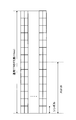
- FIG. 2 is a diagram illustrating a configuration example of the shortened TTI.
- the shortened TTI has a time length (TTI length) shorter than 1 ms.
- the shortened TTI may have at least one time length with a multiple of 1 ms, such as 0.5 ms, 0.2 ms, and 0.1 ms.
- the shortened TTI is 7/14 ms, 6/14 ms, 5/14 ms, 4/14 ms, 3/14 ms, 2/14 ms, 1/14 ms, etc. It may have at least one time length that is an integral multiple of 1/14 ms.
- FIG. 2A is a diagram illustrating a first configuration example of the shortened TTI.
- the shortened TTI is composed of the same number of symbols as the normal TTI (here, 14 symbols), and each symbol has a symbol length of the normal TTI (for example, 66. A symbol length shorter than 7 ⁇ s).
- the normal TTI physical layer signal configuration (RE arrangement or the like) can be used.
- the same amount of information (bit amount) as that of normal TTI can be included in the shortened TTI.
- the symbol time length is different from that of the normal TTI symbol, it is difficult to frequency multiplex the shortened TTI signal and the normal TTI signal shown in FIG. 2A in the same system band (or cell, CC). It becomes.
- the subcarrier interval is usually wider than 15 kHz of TTI.
- the subcarrier interval becomes wide, it is possible to effectively prevent channel-to-channel interference due to Doppler shift during movement of the user terminal and transmission quality deterioration due to phase noise of the user terminal receiver.
- a high frequency band such as several tens of GHz, it is possible to effectively prevent deterioration in transmission quality by widening the subcarrier interval.
- FIG. 2B is a diagram illustrating a second configuration example of the shortened TTI.
- the shortened TTI is configured with a smaller number of symbols than the normal TTI, and each symbol has the same symbol length (for example, 66.7 ⁇ s) as the normal TTI.
- the shortened TTI is half the time length (0.5 ms) of the normal TTI, the shortened TTI is composed of half the normal TTI symbols (here, 7 symbols).
- the information amount (bit amount) included in the shortened TTI can be reduced as compared with the normal TTI.
- the user terminal can perform reception processing (for example, demodulation, decoding, etc.) of information included in the shortened TTI in a time shorter than normal TTI, and the processing delay can be shortened.
- the shortened TTI signal and the normal TTI signal shown in FIG. 2B can be frequency-multiplexed within the same frequency band (or cell, CC), and compatibility with the normal TTI can be maintained.
- FIGS. 2A and 2B show an example of a shortened TTI that assumes a case of a normal CP (a case where a normal TTI is composed of 14 symbols), but the configuration of the shortened TTI is shown in FIGS. 2A and 2B. It is not limited to things.
- the shortened TTI in FIG. 2A may be configured with 12 symbols
- the shortened TTI in FIG. 2B may be configured with 6 symbols.
- the shortened TTI only needs to have a shorter time length than the normal TTI, and the number of symbols, the symbol length, the CP length, and the like in the shortened TTI are arbitrary.
- the shortened TTI and the normal TTI have frequencies in the same frequency band (or cell, CC). Even with division multiplexing, interference hardly occurs. Therefore, from the viewpoint of compatibility with an existing system (LTE Rel. 8-12) that supports only normal TTI, the second configuration example, that is, a shortened TTI configured with a smaller number of symbols than the normal TTI desired.
- the total number of resource elements (RE) included in one TTI (hereinafter, the total number of REs). ) Decreases.
- RE is a resource specified by subcarriers and symbols, and 1RE is composed of one subcarrier and one symbol.
- One resource block PRB: Physical Resource Block
- PRB Physical Resource Block
- not all REs can be assigned to data signals.
- an RE that maps a layer 1 / layer 2 (L1 / L2) control signal is required.
- PDCCH Physical Downlink Control Channel
- DCI Downlink Control Channel
- the number of REs required for DCI transmission can be reduced to some extent by reducing the amount of DCI information (for example, scheduling control information), a certain number of REs must be assigned to DCI.
- a cell-specific reference signal (CRS) used for downlink channel estimation consumes 16 REs (in the case of two antenna ports) per 1 PRB / 1 normal TTI. Further, 24 REs are consumed per 1 PRB / 1 normal TTI in a demodulation reference signal (DMRS: DeModulation Reference Signal) used for uplink channel estimation.
- DMRS Demodulation Reference Signal
- the number of REs required for a channel estimation reference signal can be reduced to some extent, but a certain number of REs need to be assigned to the reference signal. In some cases, it is necessary to assign a certain number of REs to reference signals other than those for channel estimation (for example, sounding reference signals (SRS)).
- SRS sounding reference signals
- the shortened TTI when the shortened TTI is configured with a smaller number of symbols than the normal TTI, how to reduce the overhead of the L1 / L2 control signal and / or the reference signal. It becomes a problem.
- the uplink as a method for reducing the overhead of the reference signal in the shortened TTI, it is also considered to share the same reference signal symbol among a plurality of shortened TTIs.
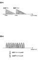
- FIG. 3 is a diagram illustrating a configuration example of PUSCH in normal TTI and shortened TTI.
- the case where the normal CP is added to each symbol is shown as an example, but the present invention is not limited to this. Applicable also when extended CP is used.
- DMRS used for PUSCH demodulation is mapped to a predetermined symbol in each slot.
- DMRS is mapped to the center symbol (symbol of index 3) of each slot.
- a predetermined symbol to which DMRS is mapped is referred to as a DMRS symbol.
- FIG. 3B shows a case where four shortened TTIs are included per normal TTI. Note that the number of shortened TTIs included in the normal TTI and the number of symbols in the shortened TTI are not limited to those shown in FIG. 3B. In FIG. 3B, DMRSs are mapped to the same symbols as normal TTIs, but the positions and number of DMRS symbols are not limited to those shown in FIG. 3B.
- a DMRS symbol (hereinafter referred to as a first DMRS symbol) in the first half slot of a normal TTI is included in both the shortened TTI-1 and the shortened TTI-2, and is shared by the shortened TTI-1 and the shortened TTI-2. Is done. Also, the DMRS symbol (hereinafter, second DMRS symbol) in the first half slot of the normal TTI is included in both the shortened TTI-3 and the shortened TTI-4, and is shared by the shortened TTI-3 and the shortened TTI-4. .
- the DMRSs of the plurality of shortened TTIs are multiplexed on the single DMRS symbol.
- the plurality of shortened TTI DMRSs may be multiplexed into a single DMRS symbol by cyclic shift (CS) and / or comb tooth-shaped subcarrier arrangement (Comb).
- CS cyclic shift
- Comb comb tooth-shaped subcarrier arrangement
- FIG. 4 is a diagram illustrating a multiplexing example of DMRSs of a plurality of shortened TTIs sharing the same DMRS symbol. Note that FIG. 4 illustrates an example of DMRS multiplexing when the first DMRS symbol is shared between the shortened TTI-1 and the shortened TTI-2 in FIG. 3B. However, in the shortened TTI-3 and the shortened TTI-4, The same applies to the case where the second DMRS symbol is shared.
- FIG. 4A shows a multiplexing example using cyclic shift.
- Each shortened TTI DMRS is generated using a different CS index and mapped to the same DMRS symbol.
- a shortened TTI-1 DMRS is generated using CS index #x
- a shortened TTI-2 DMRS is generated using CS index #y.
- the CS index of each shortened TTI may be indicated by a predetermined field in the DCI (for example, a CS / OCC indication field (Cyclic shift / Orthogonal Cover Code indicator field), a cyclic shift field (Cyclic Shift Field), etc.).
- FIG. 4B shows a multiplexing example using Comb.
- the subcarriers of Comb # 0 and # 1 are alternately arranged.
- Different Combs (subcarriers) are allocated to DMRS of each shortened TTI.
- Comb # 0 is assigned to the DMRS of shortened TTI-1
- Comb # 1 is assigned to the DMRS of shortened TTI-2.
- the plurality of DMRSs are orthogonal (completely orthogonal).
- the plurality of DMRSs may not be orthogonal if the channel frequency selectivity becomes strong.
- the plurality of DMRSs may not be orthogonal.
- the DMRSs of a plurality of shortened TTIs multiplexed on the same DMRS symbol are not orthogonal, the DMRSs of the plurality of shortened TTIs There is a possibility that interference occurs, the channel estimation accuracy decreases, and the error rate (for example, BLER: Block Error Rate) deteriorates.
- BLER Block Error Rate
- fractional TPC Fractional Transmission Power Control
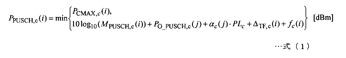
- the transmission power P PUSCH, c (i) of the PUSCH in the subframe i of the cell c can be expressed by the following formula (1).
- P CMAX, c (i) is the maximum transmission power of the user terminal.
- M PUSCH, c (i) is the bandwidth (for example, the number of resource blocks) for PUSCH allocated to the user terminal.
- P 0_PUSCH, c (j) is a parameter (for example, a parameter related to transmission power offset) (hereinafter referred to as a target received power parameter) related to target received power (target received SNR: Signal to Noise Ratio).
- ⁇ c (j) is a weighting factor of fractional TPC.
- PL c is a path loss (propagation loss).
- ⁇ TF, c (i) is an offset based on a modulation scheme and a coding rate (MCS) applied to PUSCH
- f c (i) is a correction value by a TPC command.
- P CMAX, c (i), M PUSCH, c (i), P 0_PUSCH, c (j), ⁇ c (j), PL c, ⁇ TF, c (i), f c (i) are , Except for the cell c, the subframe i, and the predetermined subscript j, respectively, may be simply expressed as P CMAX , M PUSCH , P 0_PUSCH , ⁇ , PL , ⁇ TF , f.
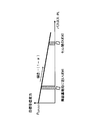
- FIG. 5 is an explanatory diagram of the fractional TPC.
- the vertical axis represents the target received power parameter (P 0_PUSCH ), and the horizontal axis represents the path loss (PL).
- P 0_PUSCH target received power parameter
- PL path loss
- FIG. 5 when the path loss is large, the user terminal exists at the cell edge, and when the path loss is small, the user terminal is considered to exist near the radio base station. Therefore, if transmission power control is performed so that the reception power of the user terminal # 1 near the radio base station is relatively large and the reception power of the user terminal # 2 at the cell edge is relatively small, the vicinity of the radio base station Can increase the throughput of the user terminal # 1 and reduce the interference given to the adjacent other cell by the user terminal # 2 far from the radio base station.
- Such control is realized by multiplying a transmission power offset that guarantees PAL loss (PL) by a predetermined weighting factor ( ⁇ ).
- the relationship between the path loss and the target received power is indicated by a primary characteristic line having a slope of ⁇ (1 ⁇ ). Therefore, when the weighting coefficient ( ⁇ ) of the fractional TPC is set to be smaller than 1, the fractional TPC is applied (enabled), and when the weighting coefficient ( ⁇ ) is set to 1, the fractional TPC is not applied ( Disabled). In this way, the presence / absence and application degree of the fractional TPC are controlled based on the set value of the weighting coefficient ( ⁇ ).
- a higher target reception power parameter (P 0_PUSCH ) is set for a user terminal closer to a radio base station (in the cell center), and therefore, the received power of the user terminal # 1 in the cell center ( The reception SNR) is higher than the reception power of the user terminal # 2 at the cell edge.
- the reception SNR is higher than the reception power of the user terminal # 2 at the cell edge.
- the uplink user throughput of the user terminal # 1 at the center of the cell is higher than that of the user terminal # 2 at the cell edge.
- the transmission power of the user terminal # 2 at the cell edge is relatively low, the influence on the adjacent other cells can be reduced.
- the fractional TPC when the fractional TPC is applied, a difference in reception power occurs between the user terminal # 1 at the center of the cell and the user terminal # 2 at the cell edge. For this reason, when the same DMRS symbol is shared between user terminals # 1 and # 2 having a difference in reception power, the DMRS of user terminal # 2 having low reception power is the DMRS of user terminal # 1 having high reception power. There is a risk of interference. In addition, it is thought that the transmission power of DMRS becomes equivalent to the transmission power of PUSCH transmitted by the same shortened TTI.
- the DMRS of user terminal # 1 in the first DMRS symbol is By fractional TPC, it is assumed that transmission is performed with larger transmission power than DMRS of user terminal # 2. In this case, channel estimation accuracy may be further reduced due to interference between DMRS of user terminals # 1 and # 2 in the first DMRS symbol.
- the DMRS of the user terminal # 1 of the shortened TTI-1 and the DMRS of the user terminal # 2 of the shortened TTI-2 are cyclically shifted or CS. Because of multiplexing, interference due to non-orthogonal DMRS of user terminals # 1 and # 2 may also occur. Therefore, in order to prevent further reduction in channel estimation accuracy, it is desired to avoid interference between DMRSs of user terminals # 1 and # 2 due to the influence of fractional TPC.
- the application of the fractional TPC is stopped or a plurality of shortened TTIs sharing the same DMRS symbol are used. It is conceivable to perform scheduling for assigning a plurality of user terminals having the same received power (path loss is the same, distance from the radio base station is the same).
- the present inventors have examined a method in which a user terminal can appropriately perform communication in both a shortened TTI and a normal TTI in a future wireless communication system in which a shortened TTI and a normal TTI are mixed.
- the present invention has been reached. Specifically, the idea was to perform different transmission power control between a user terminal assigned to a shortened TTI and a user terminal assigned to a normal TTI.
- the shortened TTI (second TTI) is configured with a smaller number of symbols than the normal TTI (first TTI), and each symbol has the same symbol length as the normal TTI.
- the present invention is not limited to this (see FIG. 2B).
- the shortened TTI of this embodiment can be applied as appropriate to the configuration example shown in FIG. 2A. Note that the number of symbols constituting the shortened TTI is, for example, 2, 4, 5, 6, 7, but is not limited thereto.
- the shortened TTI is also called partial TTI (partial TTI), short TTI, shortened TTI, shortened subframe, short subframe, etc.
- normal TTI is usually TTI, long TTI, lTTI, normal TTI. Also called a normal subframe, a long subframe, a normal subframe, or simply a subframe.
- the normal CP may be applied to each symbol in the normal TTI and / or the shortened TTI, or the extended CP may be applied. Whether the normal CP or the extended CP is applied in the shortened TTI and / or may be configured by higher layer signaling such as broadcast information and RRC (Radio Resource Control) signaling.
- RRC Radio Resource Control
- a user terminal performs uplink and / or downlink communication with a radio base station in normal TTI (first TTI) and / or shortened TTI (second TTI). Do. Specifically, the user terminal may transmit PUSCH in normal TTI and / or shortened TTI.
- a user terminal controls the transmission power of the said PUSCH based on the separate parameter separately set according to the time length (TTI length) of TTI which transmits PUSCH.
- the user terminal may control the transmission power of the PUSCH based on a common parameter that is set in common regardless of the TTI length for transmitting the PUSCH.
- the individual parameter is a parameter set for each TTI length (that is, a parameter set individually for normal TTI and shortened TTI).
- the individual parameter may include at least one of a weighting factor for fractional TPC, a target received power parameter for PUSCH, and a correction value based on a TPC command.
- the common parameter is a parameter that is commonly set for each TTI length (that is, a parameter that is commonly set for the normal TTI and the shortened TTI).
- the common parameter may include at least one of the maximum transmission power of the user terminal, the transmission bandwidth of the PUSCH, the path loss, the offset based on the MCS of the PUSCH, and the correction value by the TPC command.
- individual parameters and common parameters for normal TTI are broadcast information and / or user terminal-specific control information (hereinafter referred to as UE-specific control information) notified by higher layer signaling or L1 / L2 control signals. (That is, it may be included in broadcast information and / or UE-specific control information, or may be calculated based on information included in broadcast information and / or UE-specific control information) .
- UE-specific control information user terminal-specific control information
- the individual parameter for shortened TTI is set based on UE specific control information additionally notified by higher layer signaling or L1 / L2 control signal (that is, may be included in the UE specific control information, It may be calculated based on information included in the UE-specific control information).
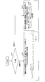
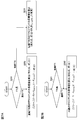
- the user terminal determines the TTI length (whether it is a normal TTI or a shortened TTI) for transmitting PUSCH (step S101).
- the user terminal When transmitting PUSCH in normal TTI, the user terminal uses individual parameters for normal TTI (for example, fractional TPC weighting factor ( ⁇ ) and target received power parameter (P 0_PUSCH )) and common parameters (for example, maximum transmission power).
- PUSCH transmission power is determined based on (P CMAX ), PUSCH transmission bandwidth (M PUSCH ), path loss (PL), MCS-based offset ( ⁇ TF ) and TPC command correction value (f)).
- P CMAX PUSCH transmission bandwidth
- PL path loss
- ⁇ TF MCS-based offset
- TPC command correction value f
- the maximum transmission power (P CMAX ) and the weighting factor ( ⁇ ) of fractional TPC may be included in UE-specific control information that is signaled by higher layers.
- the target received power parameter (P 0_PUSCH) is calculated on the basis of a predetermined target transmission power (P 0_NOMINAL_PUSCH) and user terminals individual target transmission power (P 0_UE_PUSCH), the target transmission power (P 0_NOMINAL_PUSCH, P 0_UE_PUSCH) is , It may be included in the UE-specific control information signaled by higher layer signaling.
- the path loss (PL) may be calculated based on the transmission power and reception power of the reference signal, and the transmission power may be included in the UE-specific control information that is signaled by higher layers.
- the offset ( ⁇ TF ) may be calculated based on an offset that is signaled by a higher layer.
- the transmission bandwidth (M PUSCH ) may be specified by DCI.
- the correction value (f) by the TPC command may be a value of the TPC command included in the DCI, or may be a cumulative value of the TPC command included in the DCI.
- the user terminal uses the individual parameters for the shortened TTI (for example, the fractional TPC weighting factor ( ⁇ _shortTTI ) and the target received power parameter (P 0_PUSCH_shortTTI )) and the common parameter (for example, PUSCH transmission power based on maximum transmission power (P CMAX ), PUSCH transmission bandwidth (M PUSCH ), path loss (PL), MCS offset ( ⁇ TF ) and TPC command correction value (f)) Is determined (step 103).
- the user terminal changes a part of the existing transmission power control parameters (parameters used in the above equation (1)) for the shortened TTI, and transmits the PUSCH transmission power. Can be determined.
- the fractional TPC weighting factor ( ⁇ _shortTTI ) for shortened TTI may be included in the UE-specific control information that is signaled in higher layers, separately from the fractional TPC weighting factor ( ⁇ ). Further, the target received power parameter (P 0_PUSCH_shortTTI ) for shortened TTI is set to a value suitable for the weighting factor ( ⁇ _shortTTI ). The target received power parameter (P 0_PUSCH_shortTTI ) may be included in UE-specific control information that is signaled by higher layers, or may be calculated based on target received power (P 0_NOMINAL_PUSCH , P 0_UE_PUSCH ) that is signaled by higher layers. Good.
- the arrangement and number of reference signals, the data coding rate, and the like may be different between normal TTI and shortened TTI PUSCH. In such a case, it is possible that the appropriate required SNR is different. Therefore, the shorter the weighting coefficients of fractional TPC for TTI ( ⁇ _shortTTI) and the target received power parameter (P 0_PUSCH_shortTTI) is the weighting factor of a fractional TPC for normal TTI and (alpha) and the target received power parameter (P 0_PUSCH) May be selectable from different parameter sets.
- PO_PUSCH_shortTTI can be selected from a value larger than PO_PUSCH .
- ⁇ _shortTTI can be selected from a value larger than ⁇ .
- step S102 of FIG. 6 the weighting coefficient ( ⁇ ) of the fractional TPC used in normal TTI is set to be smaller than 1.
- the weighting factor ( ⁇ ) is set to be smaller than 1
- the fractional TPC is enabled and the target received power parameter (P 0_PUSCH ) is set based on the path loss (PL).
- the user terminal # 1 in the cell center can transmit the PUSCH with a larger transmission power than the user terminal # 2 at the cell edge, so that the throughput of the user terminal # 1 can be improved.
- the weighting coefficient ( ⁇ _shortTTI ) used for the shortened TTI is set to a larger value (for example, 1) than the weighting coefficient for the fractional TPC used for the normal TTI.
- the weighting factor ( ⁇ _shortTTI ) is set to 1
- the fractional TPC is invalidated, and the target received power parameter (P 0_PUSCH_shortTTI ) does not vary due to the path loss (PL). For this reason, even when the same DMRS symbol is shared between user terminals # 1 and # 2 whose path loss (reception power) is significantly different (see FIG.
- the DMRS of user terminal # 2 with low reception power is Interference received from DMRS of user terminal # 1 having high reception power can be reduced. Even if the weight coefficient ( ⁇ _shortTTI ) is 0.9 or the like, a certain effect can be obtained.
- FIG. 6 demonstrated the case where the weighting coefficient of fractional TPC and a target received power parameter were used as an individual parameter, it is not restricted to this.
- the individual parameters are other transmission power control parameters used in the above equation (1) (for example, maximum transmission power for shortened TTI, transmission bandwidth of PUSCH for shortened TTI, path loss for shortened TTI, offset for shortened TTI. , At least one of the correction values of the TPC command for the shortened TTI) and other parameters not used in the above equation (1).
- the individual parameter for the shortened TTI may be notified by an information element (IE) different from the individual parameter for the normal TTI.
- IE information element
- the transmission power of PUSCH is controlled based on individual parameters set according to each TTI length. Therefore, even when a plurality of TTIs having different time lengths coexist, transmission power control according to each TTI length can be performed, and communication can be performed appropriately.
- fractional TPC when PUSCH is transmitted with normal TTI, fractional TPC is enabled, and when PUSCH is transmitted with shortened TTI, fractional TPC is disabled. Therefore, normal TTI can provide throughput according to the path loss (position, received power) of the user terminal. Further, in the shortened TTI, even when the same DMRS symbol is shared between user terminals with different path losses (see FIG. 3B), it is possible to prevent a decrease in channel estimation accuracy due to interference between DMRSs of the user terminals.
- the individual parameter for TTI may be set to enable fractional TPC (that is, the weighting factor ( ⁇ _shortTTI ) is smaller than 1).
- the correction value of the TPC command used for determining the PUSCH transmission power will be described in detail.
- the correction value of the TPC command may be a cumulative value of the TPC command included in the DCI.
- the accumulated value of the TPC command may be calculated for each TTI length, or may be calculated in common regardless of the TTI length.
- FIG. 7 is a diagram illustrating a calculation example of the accumulated value of the TPC command according to the present embodiment. Note that steps S201 and S301 in FIGS. 7A and 7B are the same as step S101 in FIG. Note that step S301 in FIG. 7B may be omitted.
- FIG. 7A shows a case where the correction value of the TPC command is a cumulative value of the TPC command calculated for each TTI length.
- the user terminal when transmitting a PUSCH in normal TTI, the user terminal calculates a cumulative value (f) of TPC commands using, for example, Equation (2) (step S202).
- the user terminal calculates the accumulated value of the TPC command of the shortened TTI separately from the accumulated value of the TPC command of the normal TTI (Step S203). For example, the accumulated values (f c (i), f c (i ⁇ 1)) of the expression (2) are changed to the accumulated values for the shortened TTI (f shortTTI (i), f shortTTI (i ⁇ 1)). Also good.
- the individual parameter set individually for the normal TTI and the shortened TTI may include a correction value (cumulative value) based on the TPC command.
- FIG. 7B shows a case where the correction value (f) of the TPC command is a cumulative value of TPC commands calculated in common regardless of the TTI length.
- the correction value (f) of the TPC command is a cumulative value of TPC commands calculated in common regardless of the TTI length.
- the transmission power can be determined based on the cumulative value before switching even when the TTI length is suddenly switched. , PUSCH transmission power can be maintained appropriately.
- the TTI length used for PUSCH transmission may be set semi-statically by higher layer signaling such as RRC signaling, or may be an L1 / L2 control signal (for example, an instruction included in DCI). Information) may be set dynamically.
- the TTI length used for PUSCH transmission may be set implicitly. For example, when a shortened TTI is set and a handover procedure or a random access procedure occurs, the user terminal sets the TTI length used for PUSCH transmission without explicit reconfiguration or signaling from the radio base station. You may switch from shortened TTI to normal TTI.
- the user terminal has a frequency band, a system bandwidth, whether or not to apply listening (LBT: Listen Before Talk) in an unlicensed band (LAA: License Assisted Access), data type (eg, control data, voice, etc.), logic
- LBT Listen Before Talk
- LAA License Assisted Access
- data type eg, control data, voice, etc.
- the shortened TTI may be set autonomously based on at least one of a channel, transport block, RLC (Radio Link Control) mode, C-RNTI (Cell-Radio Network Temporary Identifier), and the like.
- the DMRS sequence and / or hopping pattern may be changed according to the TTI length.
- the user terminal may determine a DMRS sequence and / or a hopping pattern using a different cell ID for each TTI length.
- a user terminal when transmitting a PUSCH with normal TTI, determines a DMRS sequence and / or hopping pattern based on a physical layer cell ID (N CELL ID ), and transmits a PUSCH with a shortened TTI.
- a DMRS sequence and / or a hopping pattern may be determined based on the ID.
- coordinated reception In order to ensure reception quality, coordinated reception (CoMP: Coordinated Multi-Point) is performed by the plurality of radio base stations with a virtual cell ID common to the plurality of radio base stations.
- Reception Non-CoMP may be performed only by a nearby radio base station.
- PUSCH transmission power control may be applied to other uplink signals such as SRS.
- the user terminal may control the transmission power of the SRS based on the individual parameter and / or the common parameter.
- wireless communication system Wireless communication system
- the radio communication method according to each of the above aspects is applied.
- wireless communication method which concerns on each said aspect may be applied independently, respectively, and may be applied in combination.
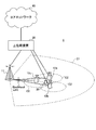
- FIG. 8 is a diagram illustrating an example of a schematic configuration of the wireless communication system according to the present embodiment.
- carrier aggregation (CA) and / or dual connectivity (DC) in which a plurality of basic frequency blocks (component carriers) each having a system bandwidth (for example, 20 MHz) of the LTE system as one unit are applied.
- the wireless communication system 1 may be referred to as SUPER 3G, LTE-A (LTE-Advanced), IMT-Advanced, 4G, 5G, FRA (Future Radio Access), or the like.
- the radio communication system 1 shown in FIG. 8 includes a radio base station 11 that forms a macro cell C1, and radio base stations 12a to 12c that are arranged in the macro cell C1 and form a small cell C2 that is narrower than the macro cell C1. . Moreover, the user terminal 20 is arrange
- the user terminal 20 can be connected to both the radio base station 11 and the radio base station 12. It is assumed that the user terminal 20 uses the macro cell C1 and the small cell C2 that use different frequencies simultaneously by CA or DC. In addition, the user terminal 20 can apply CA or DC using a plurality of cells (CC) (for example, six or more CCs).
- CC cells
- Communication between the user terminal 20 and the radio base station 11 can be performed using a carrier having a relatively low frequency band (for example, 2 GHz) and a narrow bandwidth (referred to as an existing carrier or a legacy carrier).
- a carrier having a relatively high frequency band for example, 3.5 GHz, 5 GHz, etc.
- the same carrier may be used.
- the configuration of the frequency band used by each radio base station is not limited to this.
- a wired connection for example, an optical fiber compliant with CPRI (Common Public Radio Interface), an X2 interface, etc.
- a wireless connection It can be set as the structure to do.
- the radio base station 11 and each radio base station 12 are connected to the higher station apparatus 30 and connected to the core network 40 via the higher station apparatus 30.
- the upper station device 30 includes, for example, an access gateway device, a radio network controller (RNC), a mobility management entity (MME), and the like, but is not limited thereto.
- RNC radio network controller
- MME mobility management entity
- Each radio base station 12 may be connected to the higher station apparatus 30 via the radio base station 11.
- the radio base station 11 is a radio base station having a relatively wide coverage, and may be called a macro base station, an aggregation node, an eNB (eNodeB), a transmission / reception point, or the like.
- the radio base station 12 is a radio base station having local coverage, and includes a small base station, a micro base station, a pico base station, a femto base station, a HeNB (Home eNodeB), an RRH (Remote Radio Head), and transmission / reception. It may be called a point.
- the radio base stations 11 and 12 are not distinguished, they are collectively referred to as a radio base station 10.
- Each user terminal 20 is a terminal compatible with various communication methods such as LTE and LTE-A, and may include not only a mobile communication terminal but also a fixed communication terminal.
- OFDMA orthogonal frequency division multiple access
- SC-FDMA single carrier-frequency division multiple access
- OFDMA is a multi-carrier transmission scheme that performs communication by dividing a frequency band into a plurality of narrow frequency bands (subcarriers) and mapping data to each subcarrier.
- SC-FDMA is a single-carrier transmission scheme that reduces interference between terminals by dividing the system bandwidth into bands consisting of one or continuous resource blocks for each terminal and using a plurality of terminals with mutually different bands. is there.
- the uplink and downlink radio access schemes are not limited to these combinations, and OFDMA may be used in the uplink.
- downlink channels include a downlink shared channel (PDSCH) shared by each user terminal 20, a broadcast channel (PBCH: Physical Broadcast Channel), a downlink L1 / L2 control channel, and the like. Used. User data, higher layer control information, SIB (System Information Block), etc. are transmitted by PDSCH. Also, MIB (Master Information Block) is transmitted by PBCH.
- PDSCH downlink shared channel
- PBCH Physical Broadcast Channel
- SIB System Information Block
- MIB Master Information Block
- Downlink L1 / L2 control channels include downlink control channels (PDCCH (Physical Downlink Control Channel), EPDCCH (Enhanced Physical Downlink Control Channel)), PCFICH (Physical Control Format Indicator Channel), PHICH (Physical Hybrid-ARQ Indicator Channel), etc. Including. Downlink control information (DCI: Downlink Control Information) including scheduling information of PDSCH and PUSCH is transmitted by PDCCH. The number of OFDM symbols used for PDCCH is transmitted by PCFICH. The HAICH transmission confirmation information (ACK / NACK) for PUSCH is transmitted by PHICH.
- EPDCCH is frequency-division multiplexed with PDSCH (downlink shared data channel), and is used for transmission of DCI and the like in the same manner as PDCCH.
- an uplink shared channel shared by each user terminal 20
- an uplink control channel PUCCH: Physical Uplink Control Channel
- PRACH Physical Random Access Channel
- User data and higher layer control information are transmitted by the PUSCH.
- Uplink control information including at least one of delivery confirmation information (ACK / NACK) and radio quality information (CQI) is transmitted by PUSCH or PUCCH.
- a random access preamble for establishing connection with a cell is transmitted by the PRACH.
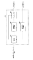
- FIG. 9 is a diagram illustrating an example of the overall configuration of the radio base station according to the present embodiment.
- the radio base station 10 includes a plurality of transmission / reception antennas 101, an amplifier unit 102, a transmission / reception unit 103, a baseband signal processing unit 104, a call processing unit 105, and a transmission path interface 106. Note that each of the transmission / reception antenna 101, the amplifier unit 102, and the transmission / reception unit 103 may be configured to include one or more.
- User data transmitted from the radio base station 10 to the user terminal 20 via the downlink is input from the higher station apparatus 30 to the baseband signal processing unit 104 via the transmission path interface 106.
- PDCP Packet Data Convergence Protocol
- RLC Radio Link Control
- MAC Medium Access
- Retransmission control for example, HARQ (Hybrid Automatic Repeat reQuest) transmission processing
- HARQ Hybrid Automatic Repeat reQuest
- the downlink control signal is also subjected to transmission processing such as channel coding and inverse fast Fourier transform, and is transferred to the transmission / reception unit 103.
- the transmission / reception unit 103 converts the baseband signal output by precoding for each antenna from the baseband signal processing unit 104 to a radio frequency band and transmits the converted signal.
- the radio frequency signal frequency-converted by the transmission / reception unit 103 is amplified by the amplifier unit 102 and transmitted from the transmission / reception antenna 101.
- the transmitter / receiver, the transmission / reception circuit, or the transmission / reception device can be configured based on common recognition in the technical field according to the present invention.
- the transmission / reception part 103 may be comprised as an integral transmission / reception part, and may be comprised from a transmission part and a receiving part.
- the radio frequency signal received by the transmission / reception antenna 101 is amplified by the amplifier unit 102.
- the transmission / reception unit 103 receives the uplink signal amplified by the amplifier unit 102.
- the transmission / reception unit 103 converts the frequency of the received signal into a baseband signal and outputs it to the baseband signal processing unit 104.
- the transmission / reception unit 103 receives the uplink signal in the normal TTI (first TTI) and / or the shortened TTI (second TTI). Specifically, the transmission / reception unit 103 receives at least one of PUSCH, PUCCH, DMRS, and SRS in normal TTI and / or shortened TTI.
- the transmission / reception unit 103 transmits parameters used for controlling the transmission power of the uplink signal. Specifically, the transmission / reception unit 103 transmits the individual parameters and / or common parameters (hereinafter referred to as individual parameters / common parameters) and / or information used for setting the individual parameters / common parameters.
- the baseband signal processing unit 104 performs Fast Fourier Transform (FFT) processing, Inverse Discrete Fourier Transform (IDFT) processing, and error correction on user data included in the input upstream signal. Decoding, MAC retransmission control reception processing, RLC layer and PDCP layer reception processing are performed and transferred to the upper station apparatus 30 via the transmission path interface 106.
- the call processing unit 105 performs call processing such as communication channel setting and release, state management of the radio base station 10, and radio resource management.
- the transmission path interface 106 transmits and receives signals to and from the higher station apparatus 30 via a predetermined interface.
- the transmission path interface 106 transmits and receives (backhaul signaling) signals to and from the adjacent radio base station 10 via an interface between base stations (for example, an optical fiber compliant with CPRI (Common Public Radio Interface), X2 interface). Also good.
- CPRI Common Public Radio Interface
- X2 interface also good.
- FIG. 10 is a diagram illustrating an example of a functional configuration of the radio base station according to the present embodiment.
- FIG. 10 mainly shows functional blocks of characteristic portions in the present embodiment, and the wireless base station 10 also has other functional blocks necessary for wireless communication.
- the baseband signal processing unit 104 includes a control unit 301, a transmission signal generation unit 302, a mapping unit 303, and a reception signal processing unit 304.
- the control unit 301 controls the entire radio base station 10.
- the control unit 301 controls, for example, downlink signal generation by the transmission signal generation unit 302, signal mapping by the mapping unit 303, and signal reception processing by the reception signal processing unit 304.
- control unit 301 performs downlink (DL) signal transmission control (for example, modulation scheme, coding rate, resource allocation (scheduling)) based on channel state information (CSI) reported from the user terminal 20. Control).
- DL downlink
- CSI channel state information
- control unit 301 controls a transmission time interval (TTI) used for receiving a downlink signal and / or transmitting an uplink signal.
- TTI transmission time interval
- the control unit 301 sets a normal TTI of 1 ms or / and a shortened TTI shorter than the normal TTI.
- the configuration example of the shortened TTI is as described with reference to FIG.
- the control unit 301 provides the user terminal 20 with an explicit notification by at least one of (1) implicit notification, or (2) RRC signaling, (3) MAC signaling, and (4) physical layer signaling. The setting of the shortened TTI may be instructed.
- control unit 301 sets parameters used for controlling the transmission power of the uplink signal. Specifically, the control unit 301 sets the individual parameter / common parameter and / or information used for setting the individual parameter / common parameter.
- control unit 301 includes, as the individual parameters, a normal TTI fractional TPC weighting factor ( ⁇ ), a shortened TTI fractional TPC weighting factor ( ⁇ _shortTTI ), and a normal TTI target received power parameter ( ⁇ ).
- ⁇ normal TTI fractional TPC weighting factor
- ⁇ _shortTTI shortened TTI fractional TPC weighting factor
- ⁇ _shortTTI normal TTI target received power parameter
- control unit 301 may set the weighting factor ( ⁇ ) for normal TTI to be smaller than 1 and validate the fractional TPC.
- the control unit 301 may set the normal TTI weight coefficient ( ⁇ _shortTTI ) to a larger value (for example, 1) than the normal TTI weight coefficient ( ⁇ ). By setting the weighting factor ( ⁇ _shortTTI ) to 1, the fractional TPC can be invalidated.
- control unit 301 uses, as the common parameters, information used to calculate the maximum transmission power (P CMAX ) of the user terminal 20, the transmission bandwidth of the PUSCH (M PUSCH ), and the path loss (PL) in the user terminal 20 (see Signal transmission power), MCS-based offset ( ⁇ TF ) or information used to calculate the offset, and a TPC command may be set.
- the control unit 301 can be configured by a controller, a control circuit, or a control device described based on common recognition in the technical field according to the present invention.
- the transmission signal generation unit 302 generates a downlink signal (including a downlink data signal, a downlink control signal, and a downlink reference signal) based on an instruction from the control unit 301, and outputs the downlink signal to the mapping unit 303.
- the transmission signal generator 302 generates a downlink data signal (PDSCH) including broadcast information, notification information (UE-specific control information) by the above-described upper layer signaling, and user data, and sends it to the mapping unit 303.
- PDSCH downlink data signal
- the transmission signal generation unit 302 generates a downlink control signal (PDCCH / EPDCCH) including the above-described DCI, and outputs it to the mapping unit 303.
- the transmission signal generation unit 302 generates downlink reference signals such as CRS and CSI-RS, and outputs them to the mapping unit 303.
- the transmission signal generation unit 302 can be a signal generator, a signal generation circuit, or a signal generation device described based on common recognition in the technical field according to the present invention.
- the mapping unit 303 maps the downlink signal generated by the transmission signal generation unit 302 to a predetermined radio resource based on an instruction from the control unit 301, and outputs it to the transmission / reception unit 103.
- the mapping unit 303 can be a mapper, a mapping circuit, or a mapping device described based on common recognition in the technical field according to the present invention.
- the reception signal processing unit 304 performs reception processing (for example, demapping, demodulation, decoding, etc.) on the uplink signal transmitted from the user terminal 20. Specifically, the reception signal processing unit 304 demodulates the PUSCH in the normal TTI and / or the shortened TTI using the DMRS received in the normal TTI and / or the shortened TTI. The processing result is output to the control unit 301.
- reception processing for example, demapping, demodulation, decoding, etc.
- the reception signal processing unit 304 may be configured by a signal processor, a signal processing circuit or a signal processing device, and a measuring device, a measurement circuit or a measuring device, which are described based on common recognition in the technical field according to the present invention. it can.
- FIG. 11 is a diagram showing an example of the overall configuration of the user terminal according to the present embodiment.
- the user terminal 20 includes a plurality of transmission / reception antennas 201 for MIMO transmission, an amplifier unit 202, a transmission / reception unit 203, a baseband signal processing unit 204, and an application unit 205.
- the radio frequency signals received by the plurality of transmission / reception antennas 201 are each amplified by the amplifier unit 202.
- Each transmitting / receiving unit 203 receives the downlink signal amplified by the amplifier unit 202.
- the transmission / reception unit 203 converts the frequency of the received signal into a baseband signal and outputs it to the baseband signal processing unit 204.
- the baseband signal processing unit 204 performs FFT processing, error correction decoding, retransmission control reception processing, and the like on the input baseband signal.
- Downlink data (user data) is transferred to the application unit 205.
- the application unit 205 performs processing related to layers higher than the physical layer and the MAC layer.
- broadcast information in the downlink data is also transferred to the application unit 205.
- the uplink data is input from the application unit 205 to the baseband signal processing unit 204.
- the baseband signal processing unit 204 performs retransmission control transmission processing (for example, HARQ transmission processing), channel coding, rate matching, puncturing, discrete Fourier transform (DFT) processing, IFFT processing, and the like. Are transferred to each transmitting / receiving unit 203. Also for UCI, channel coding, rate matching, puncturing, DFT processing, IFFT processing, and the like are performed and transferred to each transmitting / receiving section 203.
- the transmission / reception unit 203 converts the baseband signal output from the baseband signal processing unit 204 into a radio frequency band and transmits it.
- the radio frequency signal frequency-converted by the transmission / reception unit 203 is amplified by the amplifier unit 202 and transmitted from the transmission / reception antenna 201.
- the transmission / reception unit 203 transmits an uplink signal in a normal TTI (first TTI) and / or a shortened TTI (second TTI). Specifically, the transmission / reception unit 103 transmits at least one of PUSCH, PUCCH, DMRS, and SRS in normal TTI and / or shortened TTI.
- the transmission / reception unit 203 receives parameters used for controlling the transmission power of the uplink signal. Specifically, the transmission / reception unit 203 receives the individual parameter / common parameter and / or information used for setting the individual parameter / common parameter.
- the transmission / reception unit 203 can be a transmitter / receiver, a transmission / reception circuit, or a transmission / reception device described based on common recognition in the technical field according to the present invention. Further, the transmission / reception unit 203 may be configured as an integral transmission / reception unit, or may be configured from a transmission unit and a reception unit.
- FIG. 12 is a diagram illustrating an example of a functional configuration of the user terminal according to the present embodiment.
- FIG. 12 mainly shows functional blocks of characteristic portions in the present embodiment, and the user terminal 20 also has other functional blocks necessary for wireless communication.
- the baseband signal processing unit 204 included in the user terminal 20 includes a control unit 401, a transmission signal generation unit 402, a mapping unit 403, a reception signal processing unit 404, and a measurement unit 405. I have.
- the control unit 401 controls the entire user terminal 20.
- the control unit 401 controls, for example, signal generation by the transmission signal generation unit 402, signal mapping by the mapping unit 403, and signal reception processing by the reception signal processing unit 404.
- control unit 401 controls a transmission time interval (TTI) used for receiving a downlink (DL) signal and / or transmitting an uplink (UL) signal.
- TTI transmission time interval
- the control unit 301 sets a normal TTI of 1 ms or / and a shortened TTI shorter than the normal TTI.
- the configuration example of the shortened TTI is as described with reference to FIG.
- the control unit 401 is based on (1) an implicit notification from the radio base station 10 or an explicit notification by at least one of (2) RRC signaling, (3) MAC signaling, and (4) physical layer signaling.
- the shortened TTI may be set (detected).
- control unit 401 controls the transmission power of the uplink signal. Specifically, the control unit 401 controls the transmission power of the PUSCH based on individual parameters that are set according to the TTI length for transmitting the PUSCH (set separately for the normal TTI and the shortened TTI). In addition to the individual parameters, the control unit 401 sets PUSCH transmission power based on a common parameter that is set regardless of the TTI length for transmitting the PUSCH (commonly set for the normal TTI and the shortened TTI). May be controlled. In addition, the control part 401 may control the transmission power of SRS using the said individual parameter / common parameter.
- the control unit 401 uses the normal TTI individual parameters (for example, the fractional TPC weighting factor ( ⁇ ) and the target received power parameter (P 0_PUSCH )) and the common parameters (for example, PUSCH transmission power based on maximum transmission power (P CMAX ), PUSCH transmission bandwidth (M PUSCH ), path loss (PL), MCS offset ( ⁇ TF ) and TPC command correction value (f)) May be determined.
- the normal TTI individual parameters for example, the fractional TPC weighting factor ( ⁇ ) and the target received power parameter (P 0_PUSCH )
- the common parameters for example, PUSCH transmission power based on maximum transmission power (P CMAX ), PUSCH transmission bandwidth (M PUSCH ), path loss (PL), MCS offset ( ⁇ TF ) and TPC command correction value (f)
- control unit 401 may determine the transmission power of the PUSCH of the normal TTI using the above equation (1).
- control unit 401 may calculate the accumulated value (f) of the TPC command using the above equation (2).
- the control unit 401 uses individual parameters for shortened TTI (for example, fractional TPC weighting factor ( ⁇ _shortTTI ) and target received power parameter (P 0_PUSCH_shortTTI )) and common parameters (for example, , Transmission of PUSCH based on maximum transmission power (P CMAX ), PUSCH transmission bandwidth (M PUSCH ), path loss (PL), offset based on MCS ( ⁇ TF ) and correction value (f) by TPC command)
- P CMAX maximum transmission power
- M PUSCH PUSCH transmission bandwidth
- PL path loss
- ⁇ TF path loss
- correction value f
- the control unit 401 uses the normal TTI individual parameters (for example, the normal TTI fractional TPC weighting factor ( ⁇ ) and the target received power parameter (P 0_PUSCH )) in the above equation (1) for the shortened TTI.
- the individual parameters for example, the fractional TPC weight coefficient ( ⁇ _shortTTI ) and the target received power parameter (P 0_PUSCH_shortTTI )
- the control unit 401 may calculate the accumulated value (f) of the TPC command common to the normal TTI using the above equation (2).
- the accumulated value ( f_shortTTI ) of the TPC command for the shortened TTI may be calculated by changing the above equation (2).
- control unit 401 determines a DMRS sequence and / or hopping pattern based on different cell IDs for the normal TTI and the shortened TTI, and transmits the DMRS using the sequence and / or hopping pattern.
- the signal generation unit 402 may be instructed.
- the control unit 401 when PUSCH is transmitted in the shortened TTI, the control unit 401 causes the transmission signal generation unit 402 and / or the mapping unit 403 to multiplex DMRS to symbols shared with the shortened TTI and other shortened TTIs. You may control. For example, the control unit 401 may control the transmission signal generation unit 402 so as to generate a DMRS by using different CS indexes among a plurality of shortened TTIs. In addition, the control unit 401 may control the mapping unit 403 so as to allocate DMRSs to different Combs among a plurality of shortened TTIs.
- the control unit 401 can be configured by a controller, a control circuit, or a control device described based on common recognition in the technical field according to the present invention.
- the transmission signal generation unit 402 generates an uplink signal (for example, PUSCH, PUCCH, DMRS, SRS) based on an instruction from the control unit 401 (for example, encoding, rate matching, puncturing, modulation, etc.) and performs mapping. Output to the unit 403. Specifically, based on an instruction from control unit 401, transmission signal generation unit 402 generates a DMRS for PUSCH demodulation that is transmitted with a normal TTI and / or a shortened TTI.
- an uplink signal for example, PUSCH, PUCCH, DMRS, SRS
- the transmission signal generation unit 402 can be a signal generator, a signal generation circuit, or a signal generation device described based on common recognition in the technical field according to the present invention.
- the mapping unit 403 uses the uplink signal (eg, PUSCH, PUCCH, DMRS, SRS) generated by the transmission signal generation unit 402 as a radio resource (eg, PRB, subcarrier, Comb). And output to the transmission / reception unit 203.
- a radio resource eg, PRB, subcarrier, Comb.
- the reception signal processing unit 404 performs reception processing (for example, demapping, demodulation, decoding, etc.) on downlink signals (including downlink control signals, downlink data signals, and downlink reference signals).
- the reception signal processing unit 404 outputs information received from the radio base station 10 to the control unit 401.
- the received signal processing unit 404 outputs, for example, broadcast information, system information, control information (UE-specific control information) by higher layer signaling such as RRC signaling, DCI, and the like to the control unit 401.
- the received signal processing unit 404 can be configured by a signal processor, a signal processing circuit, or a signal processing device described based on common recognition in the technical field according to the present invention. Further, the reception signal processing unit 404 can constitute a reception unit according to the present invention.
- the measurement unit 405 measures the channel state based on a reference signal (for example, CSI-RS) from the radio base station 10 and outputs the measurement result to the control unit 401. Note that the channel state measurement may be performed for each CC.
- a reference signal for example, CSI-RS
- the measuring unit 405 can be composed of a signal processor, a signal processing circuit or a signal processing device, and a measuring device, a measurement circuit or a measuring device which are explained based on common recognition in the technical field according to the present invention.
- each functional block is realized by one physically coupled device, or may be realized by two or more physically separated devices connected by wire or wirelessly and by a plurality of these devices. Good.
- the radio base station, user terminal, and the like in this embodiment may function as a computer that performs processing of the radio communication method of the present invention.
- FIG. 13 is a diagram illustrating an example of a hardware configuration of the radio base station and the user terminal according to the present embodiment.
- the wireless base station 10 and the user terminal 20 described above may be physically configured as a computer device including a processor 1001, a memory 1002, a storage 1003, a communication device 1004, an input device 1005, an output device 1006, a bus 1007, and the like. Good.
- the term “apparatus” can be read as a circuit, a device, a unit, or the like.
- the hardware configurations of the radio base station 10 and the user terminal 20 may be configured to include one or a plurality of each device illustrated in the figure, or may be configured not to include some devices.
- Each function in the radio base station 10 and the user terminal 20 is obtained by reading predetermined software (program) on hardware such as the processor 1001 and the memory 1002, so that the processor 1001 performs computation, and communication by the communication device 1004, This is realized by controlling reading and / or writing of data in the memory 1002 and the storage 1003.
- the processor 1001 controls the entire computer by operating an operating system, for example.
- the processor 1001 may be configured by a central processing unit (CPU) including an interface with peripheral devices, a control device, an arithmetic device, a register, and the like.
- CPU central processing unit
- the baseband signal processing unit 104 (204) and the call processing unit 105 described above may be realized by the processor 1001.
- the processor 1001 reads programs (program codes), software modules, and data from the storage 1003 and / or the communication device 1004 to the memory 1002, and executes various processes according to these.
- programs program codes
- software modules software modules
- data data from the storage 1003 and / or the communication device 1004 to the memory 1002, and executes various processes according to these.
- the program a program that causes a computer to execute at least a part of the operations described in the above embodiments is used.
- the control unit 401 of the user terminal 20 may be realized by a control program stored in the memory 1002 and operated by the processor 1001, and may be realized similarly for other functional blocks.
- the memory 1002 is a computer-readable recording medium, and may be configured by at least one of ROM (Read Only Memory), EPROM (Erasable Programmable ROM), RAM (Random Access Memory), and the like, for example.
- the memory 1002 may be called a register, a cache, a main memory (main storage device), or the like.
- the memory 1002 can store a program (program code), a software module, and the like that can be executed to implement the wireless communication method according to the present embodiment.
- the storage 1003 is a computer-readable recording medium, and may be composed of at least one of an optical disk such as a CD-ROM (Compact Disc ROM), a hard disk drive, a flexible disk, a magneto-optical disk, and a flash memory, for example. .
- the storage 1003 may be referred to as an auxiliary storage device.
- the communication device 1004 is hardware (transmission / reception device) for performing communication between computers via a wired and / or wireless network, and is also referred to as a network device, a network controller, a network card, a communication module, or the like.
- a network device for example, the transmission / reception antenna 101 (201), the amplifier unit 102 (202), the transmission / reception unit 103 (203), the transmission path interface 106, and the like described above may be realized by the communication device 1004.
- the input device 1005 is an input device (for example, a keyboard, a mouse, etc.) that accepts external input.
- the output device 1006 is an output device (for example, a display, a speaker, etc.) that performs output to the outside.
- the input device 1005 and the output device 1006 may have an integrated configuration (for example, a touch panel).
- each device such as the processor 1001 and the memory 1002 is connected by a bus 1007 for communicating information.
- the bus 1007 may be configured with a single bus or may be configured with different buses between apparatuses.
- the radio base station 10 and the user terminal 20 may include hardware such as a microprocessor, an ASIC (Application Specific Integrated Circuit), a PLD (Programmable Logic Device), and an FPGA (Field Programmable Gate Array). A part or all of each functional block may be realized by the hardware.
- the processor 1001 may be implemented by at least one of these hardware.
- the channel and / or symbol may be a signal (signaling).
- the signal may be a message.
- a component carrier CC may be called a cell, a frequency carrier, a carrier frequency, or the like.
- the radio frame may be configured with one or a plurality of periods (frames) in the time domain.
- Each of the one or more periods (frames) constituting the radio frame may be referred to as a subframe.
- a subframe may be composed of one or more slots in the time domain.
- a slot may be composed of one or more symbols (OFDM symbols, SC-FDMA symbols, etc.) in the time domain.
- the radio frame, subframe, slot, and symbol all represent a time unit when transmitting a signal.
- Different names may be used for the radio frame, the subframe, the slot, and the symbol.
- one subframe may be referred to as a transmission time interval (TTI)
- a plurality of consecutive subframes may be referred to as a TTI
- one slot may be referred to as a TTI.
- the subframe or TTI may be a subframe (1 ms) in the existing LTE, a period shorter than 1 ms (for example, 1-13 symbols), or a period longer than 1 ms. Also good.
- TTI means, for example, a minimum time unit for scheduling in wireless communication.
- a radio base station performs scheduling to allocate radio resources (frequency bandwidth, transmission power, etc. that can be used in each user terminal) to each user terminal in units of TTI.
- the definition of TTI is not limited to this.
- a resource block is a resource allocation unit in the time domain and the frequency domain, and may include one or a plurality of continuous subcarriers (subcarriers) in the frequency domain. Further, the RB may include one or a plurality of symbols in the time domain, and may have a length of one slot, one subframe, or 1 TTI. One TTI and one subframe may each be composed of one or a plurality of resource blocks.
- the RB may be called a physical resource block (PRB: Physical RB), a PRB pair, an RB pair, or the like.
- the resource block may be composed of one or a plurality of resource elements (RE: Resource Element).
- RE Resource Element
- 1RE may be a radio resource region of 1 subcarrier and 1 symbol.
- the structure of the above-described radio frame, subframe, slot, symbol, and the like is merely an example.
- the configuration such as the cyclic prefix (CP) length can be variously changed.
- information, parameters, and the like described in this specification may be represented by absolute values, may be represented by relative values from a predetermined value, or may be represented by other corresponding information.
- the radio resource may be indicated by a predetermined index.
- software, instructions, information, etc. may be transmitted / received via a transmission medium.
- software may use websites, servers, or other devices using wired technology (coaxial cable, fiber optic cable, twisted pair and digital subscriber line (DSL), etc.) and / or wireless technology (infrared, microwave, etc.) When transmitted from a remote source, these wired and / or wireless technologies are included within the definition of transmission media.
- the radio base station in this specification may be read by the user terminal.
- each aspect / embodiment of the present invention may be applied to a configuration in which communication between a radio base station and a user terminal is replaced with communication between a plurality of user terminals (D2D: Device-to-Device).
- the user terminal 20 may have a function that the wireless base station 10 has.
- words such as “up” and “down” may be read as “side”.
- the uplink channel may be read as a side channel.
- a user terminal in this specification may be read by a radio base station.
- the wireless base station 10 may have a function that the user terminal 20 has.
- notification of predetermined information is not limited to explicitly performed, but is performed implicitly (for example, by not performing notification of the predetermined information). May be.
- notification of information is not limited to the aspect / embodiment described in this specification, and may be performed by other methods.
- notification of information includes physical layer signaling (eg, DCI (Downlink Control Information), UCI (Uplink Control Information)), upper layer signaling (eg, RRC (Radio Resource Control) signaling, broadcast information (MIB (Master Information Block)). ), SIB (System Information Block), etc.), MAC (Medium Access Control) signaling), other signals, or a combination thereof.
- the RRC signaling may be referred to as an RRC message, and may be, for example, an RRC connection setup (RRCConnectionSetup) message, an RRC connection reconfiguration (RRCConnectionReconfiguration) message, or the like.
- the MAC signaling may be notified by, for example, a MAC control element (MAC CE (Control Element)).
- MAC CE Control Element
- Each aspect / embodiment described herein includes LTE (Long Term Evolution), LTE-A (LTE-Advanced), LTE-B (LTE-Beyond), SUPER 3G, IMT-Advanced, 4G (4th generation mobile). communication system), 5G (5th generation mobile communication system), FRA (Future Radio Access), New-RAT (Radio Access Technology), CDMA2000, UMB (Ultra Mobile Broadband), IEEE 802.11 (Wi-Fi (registered trademark)) ), IEEE 802.16 (WiMAX (registered trademark)), IEEE 802.20, UWB (Ultra-WideBand), Bluetooth (registered trademark), systems using other appropriate systems and / or extended based on these It may be applied to the next generation system.
- LTE Long Term Evolution
- LTE-A Long Term Evolution-Advanced
- LTE-B LTE-Beyond
- SUPER 3G IMT-Advanced
- communication system 5G (5th generation mobile communication system
Landscapes
- Engineering & Computer Science (AREA)
- Computer Networks & Wireless Communication (AREA)
- Signal Processing (AREA)
- Mobile Radio Communication Systems (AREA)
Abstract
Description
以下、本発明の一実施の形態に係る無線通信方法について説明する。なお、本実施の形態において、短縮TTI(第2のTTI)は、通常TTI(第1のTTI)よりも少ないシンボル数で構成され、各シンボルは、通常TTIと同一のシンボル長を有するものとするが(図2B参照)、これに限られない。例えば、本実施の形態の短縮TTIは、図2Aに示す構成例にも適宜適用可能である。なお、短縮TTIを構成するシンボル数は、例えば、2、4、5、6、7などであるが、これらに限られない。
本実施の形態において、ユーザ端末は、PUSCHを送信するTTIの時間長(TTI長)に応じて個別に設定される個別パラメータに基づいて、当該PUSCHの送信電力を制御する。また、ユーザ端末は、上記個別パラメータに加えて、PUSCHを送信するTTI長に関わらず共通に設定される共通パラメータに基づいて、当該PUSCHの送信電力を制御してもよい。
本実施の形態において、PUSCHの送信電力の決定に用いられるTPCコマンドの補正値について詳述する。上述のように、TPCコマンドの補正値は、DCIに含まれるTPCコマンドの累積値であってもよい。当該TPCコマンドの累積値は、TTI長毎に算出されてもよいし、TTI長に関わらず共通に算出されてもよい。
なお、本実施の形態において、PUSCHの送信に用いられるTTI長は、RRCシグナリングなどの上位レイヤシグナリングにより準静的に設定されてもよいし、L1/L2制御信号(例えば、DCIに含まれる指示情報)により動的に設定されてもよい。
以下、本発明の一実施の形態に係る無線通信システムの構成について説明する。この無線通信システムでは、上記各態様に係る無線通信方法が適用される。なお、上記各態様に係る無線通信方法は、それぞれ単独で適用されてもよいし、組み合わせて適用されてもよい。
図9は、本実施の形態に係る無線基地局の全体構成の一例を示す図である。無線基地局10は、複数の送受信アンテナ101と、アンプ部102と、送受信部103と、ベースバンド信号処理部104と、呼処理部105と、伝送路インターフェース106とを備えている。なお、送受信アンテナ101、アンプ部102、送受信部103は、それぞれ1つ以上を含むように構成されてもよい。
図11は、本実施の形態に係るに係るユーザ端末の全体構成の一例を示す図である。ユーザ端末20は、MIMO伝送のための複数の送受信アンテナ201と、アンプ部202と、送受信部203と、ベースバンド信号処理部204と、アプリケーション部205と、を備えている。
なお、上記実施の形態の説明に用いたブロック図は、機能単位のブロックを示している。これらの機能ブロック(構成部)は、ハードウェア及び/又はソフトウェアの任意の組み合わせによって実現される。また、各機能ブロックの実現手段は特に限定されない。すなわち、各機能ブロックは、物理的に結合した1つの装置により実現されてもよいし、物理的に分離した2つ以上の装置を有線又は無線で接続し、これら複数の装置により実現されてもよい。
Claims (10)
- 第1の伝送時間間隔(TTI)及び/又は前記第1のTTIよりも少ないシンボル数で構成される第2のTTIにおいて、上り共有チャネルを送信する送信部と、
前記上り共有チャネルの送信電力を制御する制御部と、を具備し、
前記制御部は、前記上り共有チャネルを送信するTTI長に応じて個別に設定される個別パラメータに基づいて、前記送信電力を制御することを特徴とするユーザ端末。 - 前記個別パラメータは、フラクショナル送信電力制御(TPC)の重み係数と、前記上り共有チャネルの目標受信電力に関するパラメータと、TPCコマンドによる補正値と、の少なくとも一つを含むことを特徴とする請求項1に記載のユーザ端末。
- 前記第1のTTIにおいて前記上り共有チャネルが送信される場合、前記フラクショナルTPCの重み係数は、1より小さく設定され、
前記第2のTTIにおいて前記上り共有チャネルが送信される場合、前記フラクショナルTPCの重み係数は、前記第1のTTIで用いられる前記重み係数よりも大きな値に設定されることを特徴とする請求項2に記載のユーザ端末。 - 前記制御部は、前記個別パラメータに加えて、前記第1TTI及び前記第2TTIに共通に設定される共通パラメータに基づいて、前記送信電力を制御することを特徴とする請求項1から請求項3のいずれかに記載のユーザ端末。
- 前記共通パラメータは、前記ユーザ端末の最大送信電力と、前記上り共有チャネルの送信帯域幅と、パスロスと、前記上り共有チャネルの変調及び符号化方式に基づくオフセットと、TPCコマンドによる補正値と、の少なくとも一つを含むことを特徴とする請求項1から請求項4のいずれかに記載のユーザ端末。
- 前記第1のTTI用の前記個別パラメータ及び前記共通パラメータは、報知情報、及び/又は、上位レイヤシグナリング又はL1/L2制御信号により通知される前記ユーザ端末固有の制御情報に基づいて設定され、
前記第2のTTI用の前記個別パラメータは、上位レイヤシグナリング又はL1/L2制御信号により追加で通知される前記ユーザ端末固有の制御情報に基づいて設定されることを特徴とする請求項1から請求項5のいずれかに記載のユーザ端末。 - 前記送信部は、前記第1のTTI及び/又は前記第2のTTIにおいて前記上り共有チャネルの復調用参照信号を送信し、
前記制御部は、前記第2のTTIにおいて前記上り共有チャネルが送信される場合、前記第2のTTIと他の第2のTTIと共用されるシンボルに、前記復調用参照信号を多重することを特徴とする請求項1から請求項6のいずれかに記載のユーザ端末。 - 前記TTI長は、上位レイヤシグナリングにより準静的に設定される、又は、L1/L2制御信号により動的に設定される、又は、前記ユーザ端末により自律的に設定されることを特徴とする請求項1から請求項7のいずれかに記載のユーザ端末。
- 第1の伝送時間間隔(TTI)及び/又は前記第1のTTIよりも少ないシンボル数で構成される第2のTTIにおいて、上り共有チャネルを受信する受信部と、
前記上り共有チャネルの送信電力の制御に用いられるパラメータを設定する制御部と、
前記パラメータを送信する送信部と、を具備し、
前記制御部は、前記上り共有チャネルを送信するTTI長に応じた個別パラメータを設定し、
前記送信部は、前記個別パラメータを送信することを特徴とする無線基地局。 - 第1の伝送時間間隔(TTI)及び/又は前記第1のTTIよりも少ないシンボル数で構成される第2のTTIにおける無線通信方法であって、ユーザ端末において、
前記第1のTTI及び/又は前記前記第2のTTIにおいて、上り共有チャネルを送信する工程と、
前記上り共有チャネルを送信するTTI長に応じて設定される個別パラメータに基づいて、前記上り共有チャネルの送信電力を制御する工程と、を有することを特徴とする無線通信方法。
Priority Applications (7)
| Application Number | Priority Date | Filing Date | Title |
|---|---|---|---|
| CN201780012087.6A CN108702711B (zh) | 2016-02-19 | 2017-02-16 | 用户终端、无线基站以及无线通信方法 |
| ES17753284T ES2907348T3 (es) | 2016-02-19 | 2017-02-16 | Equipo de usuario, estación base inalámbrica y método de comunicación inalámbrica |
| US15/999,242 US10568040B2 (en) | 2016-02-19 | 2017-02-16 | Terminal and radio communication method |
| BR112018016830-0A BR112018016830B1 (pt) | 2016-02-19 | 2017-02-16 | Terminal de usuário |
| EP17753284.3A EP3413638B1 (en) | 2016-02-19 | 2017-02-16 | User equipment, wireless base station, and wireless communication method |
| JP2018500198A JP6585274B2 (ja) | 2016-02-19 | 2017-02-16 | 端末及び無線通信方法 |
| ZA2018/05492A ZA201805492B (en) | 2016-02-19 | 2018-08-16 | User terminal, radio base station and radio communcation method |
Applications Claiming Priority (2)
| Application Number | Priority Date | Filing Date | Title |
|---|---|---|---|
| JP2016029884 | 2016-02-19 | ||
| JP2016-029884 | 2016-02-19 |
Publications (1)
| Publication Number | Publication Date |
|---|---|
| WO2017142029A1 true WO2017142029A1 (ja) | 2017-08-24 |
Family
ID=59625999
Family Applications (1)
| Application Number | Title | Priority Date | Filing Date |
|---|---|---|---|
| PCT/JP2017/005748 Ceased WO2017142029A1 (ja) | 2016-02-19 | 2017-02-16 | ユーザ端末、無線基地局及び無線通信方法 |
Country Status (7)
| Country | Link |
|---|---|
| US (1) | US10568040B2 (ja) |
| EP (1) | EP3413638B1 (ja) |
| JP (1) | JP6585274B2 (ja) |
| CN (1) | CN108702711B (ja) |
| ES (1) | ES2907348T3 (ja) |
| WO (1) | WO2017142029A1 (ja) |
| ZA (1) | ZA201805492B (ja) |
Cited By (6)
| Publication number | Priority date | Publication date | Assignee | Title |
|---|---|---|---|---|
| WO2019169624A1 (zh) * | 2018-03-09 | 2019-09-12 | Oppo广东移动通信有限公司 | 数据传输方法及装置 |
| EP3577956A1 (en) * | 2017-02-06 | 2019-12-11 | QUALCOMM Incorporated | Resource management for low latency wireless communications |
| JP2020519110A (ja) * | 2017-05-05 | 2020-06-25 | クアルコム,インコーポレイテッド | 低レイテンシシステムにおけるサウンディング基準信号構成およびトランスポートブロックサイズスケーリング |
| JPWO2019049332A1 (ja) * | 2017-09-08 | 2020-10-15 | 株式会社Nttドコモ | ユーザ装置、及び送信電力制御方法 |
| JP2022009070A (ja) * | 2017-05-12 | 2022-01-14 | エルジー エレクトロニクス インコーポレイティド | 無線通信システムにおいて送信電力制御のための方法及びそのための装置 |
| WO2024194983A1 (ja) * | 2023-03-20 | 2024-09-26 | 楽天モバイル株式会社 | 特定位置での特定ユーザへの通信支援 |
Families Citing this family (12)
| Publication number | Priority date | Publication date | Assignee | Title |
|---|---|---|---|---|
| CN107926016B (zh) * | 2015-09-25 | 2022-08-02 | 苹果公司 | 支持针对不同传输时间间隔的半持续调度 |
| EP3499981B1 (en) * | 2016-08-10 | 2020-09-23 | Panasonic Intellectual Property Corporation of America | Terminal and communication method |
| US11540225B2 (en) * | 2016-09-14 | 2022-12-27 | Ntt Docomo, Inc. | User terminal and radio communication method |
| US11516747B2 (en) * | 2017-05-12 | 2022-11-29 | Lg Electronics Inc. | Method for controlling transmit power in wireless communication system and apparatus therefor |
| US10855421B2 (en) * | 2017-08-10 | 2020-12-01 | Qualcomm Incorporated | Configuration of sounding reference signal resources in an uplink transmission time interval |
| EP3911039A4 (en) * | 2019-01-10 | 2022-08-17 | Ntt Docomo, Inc. | USER TERMINAL AND WIRELESS COMMUNICATION METHOD |
| CN111464218B (zh) * | 2019-01-18 | 2022-08-12 | 中国移动通信有限公司研究院 | 下行波束管理的方法及设备 |
| CN114223266B (zh) * | 2019-06-13 | 2024-04-02 | 株式会社Ntt都科摩 | 终端以及无线通信方法 |
| US20240089935A1 (en) * | 2021-01-28 | 2024-03-14 | Telefonaktiebolaget Lm Ericsson (Publ) | Control signaling for wireless communication network |
| US12114272B2 (en) | 2022-01-11 | 2024-10-08 | Qualcomm Incorporated | Gain control in sidelink |
| US12363653B2 (en) | 2022-01-11 | 2025-07-15 | Qualcomm Incorporated | Sidelink slots with multiple automatic gain control symbols |
| US12302261B2 (en) | 2022-01-11 | 2025-05-13 | Qualcomm Incorporated | Using automatic gain control symbol to indicate sidelink mini-slot |
Citations (2)
| Publication number | Priority date | Publication date | Assignee | Title |
|---|---|---|---|---|
| JP2010509843A (ja) * | 2006-11-02 | 2010-03-25 | インターデイジタル テクノロジー コーポレーション | Hsupaチャネルのe−tfc制限を最適化する方法および装置 |
| JP2015050575A (ja) * | 2013-08-30 | 2015-03-16 | 株式会社Nttドコモ | 無線基地局、ユーザ端末及び送信電力制御方法 |
Family Cites Families (11)
| Publication number | Priority date | Publication date | Assignee | Title |
|---|---|---|---|---|
| US8311053B2 (en) * | 2008-09-15 | 2012-11-13 | Infineon Technologies Ag | Methods for controlling an uplink signal transmission power and communication devices |
| CN101720122B (zh) * | 2009-12-28 | 2015-05-20 | 中兴通讯股份有限公司 | 一种物理上行控制信道的功率控制方法及基站和终端 |
| WO2013048143A2 (en) * | 2011-09-27 | 2013-04-04 | Samsung Electronics Co., Ltd. | A method and appratus for transmission power control for a sounding reference signal |
| JP6081741B2 (ja) * | 2012-08-30 | 2017-02-15 | 株式会社Nttドコモ | 移動局及び送信電力決定方法 |
| EP2894908B1 (en) * | 2012-09-28 | 2019-12-04 | Huawei Technologies Co., Ltd. | Method for power adjustment, base station, and user equipment |
| JP2016515334A (ja) * | 2013-03-04 | 2016-05-26 | エルジー エレクトロニクス インコーポレイティド | 無線通信システムにおけるアップリンク電力制御方法及びこのための装置 |
| WO2014204203A1 (ko) * | 2013-06-18 | 2014-12-24 | 엘지전자 주식회사 | 무선 자원의 용도 변경을 지원하는 무선 통신 시스템에서 전력 제어 방법 및 이를 위한 장치 |
| US10172121B2 (en) * | 2013-07-12 | 2019-01-01 | Sharp Kabushiki Kaisha | Terminal device, method, and integrated circuit |
| JP6456287B2 (ja) * | 2013-07-12 | 2019-01-23 | シャープ株式会社 | 端末装置、方法および集積回路 |
| JP5980241B2 (ja) * | 2014-01-14 | 2016-08-31 | 株式会社Nttドコモ | ユーザ端末、無線基地局及び無線通信方法 |
| CN105917709B (zh) * | 2014-01-15 | 2020-05-19 | Lg电子株式会社 | 控制无线通信中的上行链路功率的方法和装置 |
-
2017
- 2017-02-16 CN CN201780012087.6A patent/CN108702711B/zh active Active
- 2017-02-16 US US15/999,242 patent/US10568040B2/en active Active
- 2017-02-16 JP JP2018500198A patent/JP6585274B2/ja active Active
- 2017-02-16 EP EP17753284.3A patent/EP3413638B1/en active Active
- 2017-02-16 ES ES17753284T patent/ES2907348T3/es active Active
- 2017-02-16 WO PCT/JP2017/005748 patent/WO2017142029A1/ja not_active Ceased
-
2018
- 2018-08-16 ZA ZA2018/05492A patent/ZA201805492B/en unknown
Patent Citations (2)
| Publication number | Priority date | Publication date | Assignee | Title |
|---|---|---|---|---|
| JP2010509843A (ja) * | 2006-11-02 | 2010-03-25 | インターデイジタル テクノロジー コーポレーション | Hsupaチャネルのe−tfc制限を最適化する方法および装置 |
| JP2015050575A (ja) * | 2013-08-30 | 2015-03-16 | 株式会社Nttドコモ | 無線基地局、ユーザ端末及び送信電力制御方法 |
Non-Patent Citations (3)
| Title |
|---|
| HUAWEI ET AL.: "Control signaling enhancements for short TTI", 3GPP TSG RAN WG1 MEETING #83 R1-156461, 15 November 2015 (2015-11-15), XP051002921 * |
| SAMSUNG: "Study on specification impact for uplink due to TTI shortening", 3GPP TSG RAN WG1 #83 R1-156822, 15 November 2015 (2015-11-15), XP051003182 * |
| See also references of EP3413638A4 * |
Cited By (14)
| Publication number | Priority date | Publication date | Assignee | Title |
|---|---|---|---|---|
| EP3577956A1 (en) * | 2017-02-06 | 2019-12-11 | QUALCOMM Incorporated | Resource management for low latency wireless communications |
| EP3577956B1 (en) * | 2017-02-06 | 2025-08-20 | QUALCOMM Incorporated | Resource management for low latency wireless communications |
| US11160074B2 (en) | 2017-02-06 | 2021-10-26 | Qualcomm Incorporated | Resource management for low latency wireless communications |
| JP7140777B2 (ja) | 2017-05-05 | 2022-09-21 | クアルコム,インコーポレイテッド | 低レイテンシシステムにおけるサウンディング基準信号構成およびトランスポートブロックサイズスケーリング |
| JP2020519110A (ja) * | 2017-05-05 | 2020-06-25 | クアルコム,インコーポレイテッド | 低レイテンシシステムにおけるサウンディング基準信号構成およびトランスポートブロックサイズスケーリング |
| US11497007B2 (en) | 2017-05-05 | 2022-11-08 | Qualcomm Incorporated | Sounding reference signal configuration and transport block size scaling in low latency systems |
| JP2022009070A (ja) * | 2017-05-12 | 2022-01-14 | エルジー エレクトロニクス インコーポレイティド | 無線通信システムにおいて送信電力制御のための方法及びそのための装置 |
| JP7350034B2 (ja) | 2017-05-12 | 2023-09-25 | エルジー エレクトロニクス インコーポレイティド | 無線通信システムにおいて送信電力制御のための方法及びそのための装置 |
| JP7025435B2 (ja) | 2017-09-08 | 2022-02-24 | 株式会社Nttドコモ | 端末、基地局、無線通信システム及びul信号送信方法 |
| JPWO2019049332A1 (ja) * | 2017-09-08 | 2020-10-15 | 株式会社Nttドコモ | ユーザ装置、及び送信電力制御方法 |
| US11601892B2 (en) | 2017-09-08 | 2023-03-07 | Ntt Docomo, Inc. | User apparatus and transmission power control method |
| WO2019169624A1 (zh) * | 2018-03-09 | 2019-09-12 | Oppo广东移动通信有限公司 | 数据传输方法及装置 |
| CN111418237A (zh) * | 2018-03-09 | 2020-07-14 | Oppo广东移动通信有限公司 | 数据传输方法及装置 |
| WO2024194983A1 (ja) * | 2023-03-20 | 2024-09-26 | 楽天モバイル株式会社 | 特定位置での特定ユーザへの通信支援 |
Also Published As
| Publication number | Publication date |
|---|---|
| EP3413638A1 (en) | 2018-12-12 |
| BR112018016830A2 (ja) | 2018-12-26 |
| ES2907348T3 (es) | 2022-04-22 |
| EP3413638B1 (en) | 2022-02-09 |
| JPWO2017142029A1 (ja) | 2018-12-13 |
| CN108702711A (zh) | 2018-10-23 |
| CN108702711B (zh) | 2021-10-22 |
| US10568040B2 (en) | 2020-02-18 |
| EP3413638A4 (en) | 2019-01-16 |
| JP6585274B2 (ja) | 2019-10-02 |
| ZA201805492B (en) | 2021-03-31 |
| US20190116559A1 (en) | 2019-04-18 |
Similar Documents
| Publication | Publication Date | Title |
|---|---|---|
| JP6585274B2 (ja) | 端末及び無線通信方法 | |
| CN108293035B (zh) | 用户终端、无线基站及无线通信方法 | |
| JP6954841B2 (ja) | ユーザ端末及び無線基地局 | |
| US10555280B2 (en) | User terminal, radio base station and radio communication method | |
| JPWO2017130993A1 (ja) | ユーザ端末、無線基地局及び無線通信方法 | |
| WO2017038894A1 (ja) | ユーザ端末、無線基地局及び無線通信方法 | |
| JP6865501B2 (ja) | 端末、無線基地局及び無線通信方法 | |
| WO2017130991A1 (ja) | ユーザ端末、無線基地局及び無線通信方法 | |
| JPWO2017164147A1 (ja) | ユーザ端末、無線基地局及び無線通信方法 | |
| WO2017164222A1 (ja) | ユーザ端末、無線基地局及び無線通信方法 | |
| WO2017130990A1 (ja) | ユーザ端末、無線基地局及び無線通信方法 | |
| JPWO2017150451A1 (ja) | ユーザ端末、無線基地局及び無線通信方法 | |
| CN107950066B (zh) | 用户终端、无线基站及无线通信方法 | |
| CN111699642A (zh) | 用户终端以及无线通信方法 | |
| WO2017164141A1 (ja) | ユーザ端末、無線基地局及び無線通信方法 | |
| WO2019193769A1 (ja) | ユーザ端末 | |
| WO2017150448A1 (ja) | ユーザ端末、無線基地局及び無線通信方法 | |
| CN108702754B (zh) | 用户终端、无线基站以及无线通信方法 | |
| JP7010696B2 (ja) | 端末及び無線通信方法 | |
| BR112018016830B1 (pt) | Terminal de usuário |
Legal Events
| Date | Code | Title | Description |
|---|---|---|---|
| 121 | Ep: the epo has been informed by wipo that ep was designated in this application |
Ref document number: 17753284 Country of ref document: EP Kind code of ref document: A1 |
|
| WWE | Wipo information: entry into national phase |
Ref document number: 2018500198 Country of ref document: JP |
|
| NENP | Non-entry into the national phase |
Ref country code: DE |
|
| REG | Reference to national code |
Ref country code: BR Ref legal event code: B01A Ref document number: 112018016830 Country of ref document: BR |
|
| WWE | Wipo information: entry into national phase |
Ref document number: 2017753284 Country of ref document: EP |
|
| ENP | Entry into the national phase |
Ref document number: 2017753284 Country of ref document: EP Effective date: 20180905 |
|
| ENP | Entry into the national phase |
Ref document number: 112018016830 Country of ref document: BR Kind code of ref document: A2 Effective date: 20180816 |