WO2017143730A1 - 一种云台相机重心调节机构、云台及飞行器 - Google Patents
一种云台相机重心调节机构、云台及飞行器 Download PDFInfo
- Publication number
- WO2017143730A1 WO2017143730A1 PCT/CN2016/093591 CN2016093591W WO2017143730A1 WO 2017143730 A1 WO2017143730 A1 WO 2017143730A1 CN 2016093591 W CN2016093591 W CN 2016093591W WO 2017143730 A1 WO2017143730 A1 WO 2017143730A1
- Authority
- WO
- WIPO (PCT)
- Prior art keywords
- axis direction
- center
- adjustment mechanism
- pan
- camera
- Prior art date
- Legal status (The legal status is an assumption and is not a legal conclusion. Google has not performed a legal analysis and makes no representation as to the accuracy of the status listed.)
- Ceased
Links
Images




Classifications
-
- G—PHYSICS
- G03—PHOTOGRAPHY; CINEMATOGRAPHY; ANALOGOUS TECHNIQUES USING WAVES OTHER THAN OPTICAL WAVES; ELECTROGRAPHY; HOLOGRAPHY
- G03B—APPARATUS OR ARRANGEMENTS FOR TAKING PHOTOGRAPHS OR FOR PROJECTING OR VIEWING THEM; APPARATUS OR ARRANGEMENTS EMPLOYING ANALOGOUS TECHNIQUES USING WAVES OTHER THAN OPTICAL WAVES; ACCESSORIES THEREFOR
- G03B17/00—Details of cameras or camera bodies; Accessories therefor
- G03B17/56—Accessories
- G03B17/561—Support related camera accessories
-
- B—PERFORMING OPERATIONS; TRANSPORTING
- B64—AIRCRAFT; AVIATION; COSMONAUTICS
- B64D—EQUIPMENT FOR FITTING IN OR TO AIRCRAFT; FLIGHT SUITS; PARACHUTES; ARRANGEMENT OR MOUNTING OF POWER PLANTS OR PROPULSION TRANSMISSIONS IN AIRCRAFT
- B64D47/00—Equipment not otherwise provided for
- B64D47/08—Arrangements of cameras
-
- F—MECHANICAL ENGINEERING; LIGHTING; HEATING; WEAPONS; BLASTING
- F16—ENGINEERING ELEMENTS AND UNITS; GENERAL MEASURES FOR PRODUCING AND MAINTAINING EFFECTIVE FUNCTIONING OF MACHINES OR INSTALLATIONS; THERMAL INSULATION IN GENERAL
- F16M—FRAMES, CASINGS OR BEDS OF ENGINES, MACHINES OR APPARATUS, NOT SPECIFIC TO ENGINES, MACHINES OR APPARATUS PROVIDED FOR ELSEWHERE; STANDS; SUPPORTS
- F16M11/00—Stands or trestles as supports for apparatus or articles placed thereon ; Stands for scientific apparatus such as gravitational force meters
- F16M11/02—Heads
- F16M11/04—Means for attachment of apparatus; Means allowing adjustment of the apparatus relatively to the stand
- F16M11/043—Allowing translations
-
- F—MECHANICAL ENGINEERING; LIGHTING; HEATING; WEAPONS; BLASTING
- F16—ENGINEERING ELEMENTS AND UNITS; GENERAL MEASURES FOR PRODUCING AND MAINTAINING EFFECTIVE FUNCTIONING OF MACHINES OR INSTALLATIONS; THERMAL INSULATION IN GENERAL
- F16M—FRAMES, CASINGS OR BEDS OF ENGINES, MACHINES OR APPARATUS, NOT SPECIFIC TO ENGINES, MACHINES OR APPARATUS PROVIDED FOR ELSEWHERE; STANDS; SUPPORTS
- F16M13/00—Other supports for positioning apparatus or articles; Means for steadying hand-held apparatus or articles
- F16M13/02—Other supports for positioning apparatus or articles; Means for steadying hand-held apparatus or articles for supporting on, or attaching to, an object, e.g. tree, gate, window-frame, cycle
-
- G—PHYSICS
- G03—PHOTOGRAPHY; CINEMATOGRAPHY; ANALOGOUS TECHNIQUES USING WAVES OTHER THAN OPTICAL WAVES; ELECTROGRAPHY; HOLOGRAPHY
- G03B—APPARATUS OR ARRANGEMENTS FOR TAKING PHOTOGRAPHS OR FOR PROJECTING OR VIEWING THEM; APPARATUS OR ARRANGEMENTS EMPLOYING ANALOGOUS TECHNIQUES USING WAVES OTHER THAN OPTICAL WAVES; ACCESSORIES THEREFOR
- G03B15/00—Special procedures for taking photographs; Apparatus therefor
- G03B15/006—Apparatus mounted on flying objects
-
- G—PHYSICS
- G03—PHOTOGRAPHY; CINEMATOGRAPHY; ANALOGOUS TECHNIQUES USING WAVES OTHER THAN OPTICAL WAVES; ELECTROGRAPHY; HOLOGRAPHY
- G03B—APPARATUS OR ARRANGEMENTS FOR TAKING PHOTOGRAPHS OR FOR PROJECTING OR VIEWING THEM; APPARATUS OR ARRANGEMENTS EMPLOYING ANALOGOUS TECHNIQUES USING WAVES OTHER THAN OPTICAL WAVES; ACCESSORIES THEREFOR
- G03B17/00—Details of cameras or camera bodies; Accessories therefor
- G03B17/56—Accessories
Definitions
- the present application relates to the field of camera equipment technology, and in particular, to a pan-tilt camera center-of-gravity adjustment mechanism, a cloud platform, and an aircraft.
- the gimbal is used to mount, secure and support the photographic equipment.
- the center of gravity adjustment mechanism on the existing gimbal is slow in speed and accuracy is not accurate enough.
- How to design a center-of-gravity adjustment mechanism of the PTZ camera to achieve fast and accurate fine-tuning of the center of gravity of the camera is a problem to be solved in the prior art.
- the present application provides a center-of-gravity adjustment mechanism, a pan/tilt head and an aircraft of a pan-tilt camera, which solves the problem that the speed adjustment mechanism of the center of gravity camera of the existing pan-tilt camera is slow and the accuracy is not accurate enough.
- a pan-tilt camera center-of-gravity adjustment mechanism includes a camera base disposed on the pan/tilt head and a slide table located under the camera base, and further includes: adjusting the center of gravity of the camera by using a gear meshing rack in three directions The X-axis direction center of gravity adjustment mechanism, the Y-axis direction center of gravity adjustment mechanism, and the Z-axis direction center of gravity adjustment mechanism.
- the X-axis direction center of gravity adjustment mechanism is located at the bottom of the camera base, and includes an X-axis direction guide post, an X-axis direction gear, and an X-axis direction knob, and the X-axis direction gear upper end and the slide
- the table is fixedly connected, and the lower end is fixedly connected to the X-axis direction knob, and the X-axis direction gear meshes with the rack on the inner side of the X-axis direction guiding column;
- the Y-axis direction center of gravity adjustment mechanism is located at a side of the camera base, and includes a Y-axis direction gear and a Y-axis direction knob, and the Y-axis direction gear is fixedly connected to the Y-axis direction knob and is set on the slide table. Internally, the Y-axis direction gear meshes with a rack at the bottom of the camera base;
- the Z-axis direction center of gravity adjustment mechanism is located on both sides of the X-axis direction guide column, and includes a Z-axis direction guide column, a Z-axis direction gear, a Z-axis direction knob, a support block and a fixed block, and the upper end of the support block is a sliding table is connected, and a lower end is set on the X-axis direction guiding column, and the X-axis direction guiding column
- the Z-axis direction gear is fixedly connected to the Z-axis direction knob and is disposed on the fixing block, and the Z-axis direction gear is coupled to the Z-axis direction guide post.
- the racks on the inner side of the guide post in the Z-axis direction are engaged.
- the camera base is engraved with a unit scale strip on the side
- the slide table is engraved with a scale strip aligned with the unit scale strip on the camera base.
- the X-axis direction guide post and the Z-axis direction guide post are each engraved with a unit scale bar.
- the Z-axis direction center of gravity adjustment mechanism has at least two.
- the present application provides a pan/tilt head, comprising: a pan-tilt body body and a pan-tilt camera center-of-gravity adjusting mechanism, the adjusting mechanism includes a camera base disposed on the pan/tilt head, and located under the camera base
- the adjustment mechanism further includes: an X-axis direction center of gravity adjustment mechanism for adjusting the center of gravity of the camera by the operation of the gear meshing rack in three directions, a Y-axis direction center of gravity adjustment mechanism, and a Z-axis direction center of gravity adjustment mechanism.
- the X-axis direction center of gravity adjustment mechanism is located at the bottom of the camera base, and includes an X-axis direction guide post, an X-axis direction gear, and an X-axis direction knob, and the X-axis direction gear upper end and the slide
- the table is fixedly connected, and the lower end is fixedly connected to the X-axis direction knob, and the X-axis direction gear meshes with the rack on the inner side of the X-axis direction guiding column;
- the Y-axis direction center of gravity adjustment mechanism is located at a side of the camera base, and includes a Y-axis direction gear and a Y-axis direction knob, and the Y-axis direction gear is fixedly connected to the Y-axis direction knob and is set on the slide table. Internally, the Y-axis direction gear meshes with a rack at the bottom of the camera base;
- the Z-axis direction center of gravity adjustment mechanism is located on both sides of the X-axis direction guide column, and includes a Z-axis direction guide column, a Z-axis direction gear, a Z-axis direction knob, a support block and a fixed block, and the upper end of the support block is a sliding table is connected, the lower end is set on the X-axis direction guiding column, and the X-axis direction guiding column is set on the Z-axis direction guiding column through the fixing block, the Z-axis direction gear and the Z-axis
- the direction knob is fixedly coupled and disposed on the fixed block, and the Z-axis direction gear meshes with the rack on the inner side of the Z-axis direction guide post.
- the camera base is engraved with a unit scale strip on the side
- the slide table is engraved with a scale strip aligned with the unit scale strip on the camera base.
- the X-axis direction guide post and the Z-axis direction guide post are each engraved with a unit scale bar.
- the present application also provides an aircraft, including: an aircraft body, The camera and the pan/tilt described in this application.
- the utility model has the beneficial effects of providing a pan-tilt camera center-of-gravity adjusting mechanism, a pan/tilt head and an aircraft, and the pan-tilt camera center-of-gravity adjusting mechanism can respectively perform three directions of an X-axis direction, a Y-axis direction and a Z-axis direction for different cameras.
- the mechanism's pan/tilt has the characteristics of compact structure and beautiful appearance while realizing the camera's center of gravity.
- the aircraft with the pan/tilt has high aerial quality, which can quickly and accurately adjust the position of the center of gravity of the camera required for shooting.
- FIG. 1 is a schematic structural diagram of a center-of-gravity adjustment mechanism of a pan-tilt camera according to Embodiment 1 of the present application;
- Part A X-axis direction center of gravity adjustment mechanism
- Part B Z-axis direction center of gravity adjustment mechanism
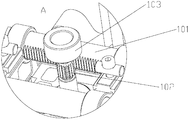
- Figure 3 is an enlarged schematic view of a portion A of Figure 2;
- Figure 4 is an enlarged schematic view of a portion B of Figure 2;
- FIG. 5 is a schematic structural diagram of a center-of-gravity adjustment mechanism of a center-of-gravity adjustment mechanism of a pan-tilt camera according to Embodiment 1 of the present application;
- FIG. 6 is a schematic structural view of the inside of a center-of-gravity adjusting mechanism of a Y-axis direction of a center-of-gravity adjusting mechanism of a pan-tilt camera according to Embodiment 1 of the present application.
- the present application provides a pan-tilt camera center-of-gravity adjustment mechanism, which includes a camera base 40 disposed on a pan/tilt, and a slide table 50 located below the camera base 40.
- the camera base 40 is engraved with a unit scale strip on the side thereof, and the slide table 50 is engraved with a scale strip aligned with the unit scale strip on the camera base 40.
- the center of gravity adjustment mechanism further includes: an X-axis direction center of gravity adjustment mechanism 10, a Y-axis direction center of gravity adjustment mechanism 20, and a Z-axis direction center of gravity adjustment mechanism 30 for adjusting the center of gravity of the camera by means of a gear meshing rack in three directions, wherein:
- the X-axis direction center of gravity adjustment mechanism 10 is located at the bottom of the camera base 40, and includes an X-axis direction guide post 101, an X-axis direction gear 102, and an X-axis direction knob 103, and the X-axis direction gear 102 upper end and the slide
- the table 50 is fixedly connected, and the lower end is fixedly connected to the X-axis direction knob 103, preferably in an adhesive connection, and the X-axis direction gear 102 meshes with the evenly distributed rack on the inner side of the X-axis direction guiding column 101.
- a unit scale strip is engraved on the outer side of the X-axis direction guide post 101.
- the Y-axis direction center of gravity adjustment mechanism 20 is located at a side of the camera base 40 and includes a Y-axis direction gear 101 and a Y-axis direction knob 102, and the Y-axis direction gear 101 is fixedly connected to the Y-axis direction knob 102 and Suitably disposed in the slide table 50, preferably in an adhesive connection, the Y-axis direction gear 101 meshes with a uniformly distributed rack at the bottom of the camera base 40;
- the Z-axis direction center of gravity adjustment mechanism 30 has at least two, respectively located on both sides of the X-axis direction guiding column 101, and includes a Z-axis direction guiding column 301, a Z-axis direction gear 302, a Z-axis direction knob 303, and a support block 60.
- the fixing block 70 the upper end of the supporting block 60 is connected to the sliding table 50, the lower end is set on the X-axis direction guiding column 101, and the X-axis direction guiding column 101 is set by the fixing block 70 a Z-axis direction guiding column 301, the Z-axis direction gear 302 is fixedly connected to the Z-axis direction knob 303 and is disposed on the fixing block 70, preferably, a bonding connection, the Z-axis direction gear 302 is meshed with a uniformly distributed rack on the inner side of the Z-axis direction guide post 301, and a unit scale strip is engraved on the outside of the Z-axis direction guide post 301.
- the pan-tilt center of gravity adjustment mechanism can perform the X-axis direction and the Y-axis direction for the center of gravity of different cameras during shooting.
- the X-axis direction gear 102 is fixedly connected with the X-axis direction knob 103, the X-axis direction knob 103 is rotated.
- the X-axis direction gear 102 is moved, and the X-axis direction gear 102 meshes with the rack inside the X-axis direction guiding column 101 to guide the X-axis direction gear 102 to guide along the X-axis direction.
- Column 101 moves, said X
- the upper end of the shaft-direction gear 102 is fixedly coupled to the slide table 50.
- the X-axis direction gear 102 moves to move the slide table 50, and the slide table 50 is located below the camera base 40 and passes through the limit slot. Connected to the camera base 40, the movement of the slide table 50 will drive the camera base 40 to move, so rotating the X-axis direction knob 103 will eventually cause the camera base 40 to follow the X-axis direction.
- the guiding column 101 is moved to the left and right; when the camera needs to be adjusted back and forth, the Y-axis direction knob 202 is rotated, and the Y-axis direction gear 201 is fixedly connected with the Y-axis direction knob 202, and the Y-axis direction is rotated.
- the knob 202 drives the Y-axis direction gear 201 to move, and the Y-axis direction gear 201 meshes with the rack at the bottom of the camera base 40 to drive the camera base 40 to move, thereby rotating the Y
- the axis direction knob 202 finally causes the camera base 40 to move back and forth.
- the Y-axis direction knob 202 is fitted in the slide table 50, and the slide table 50 is engraved with the camera base 40.
- the design makes the center of gravity adjustment mechanism knot Compact and beautiful, it is easy to observe the change of the adjustment distance, making the adjustment easier to control and achieving fast and accurate adjustment.
- the Z-axis knob 303 is rotated, due to the Z-axis direction.
- the gear 302 is fixedly connected to the Z-axis direction knob 303, and the Z-axis direction knob 303 is rotated to drive the Z-axis direction gear 302 to move.
- the Z-axis direction gear 302 and the Z-axis direction guiding column 301 The inner rack gear is engaged to move the Z-axis direction gear 302 along the Z-axis direction guiding post 301.
- the Z-axis direction gear 302 Since the Z-axis direction gear 302 is disposed on the fixing block 70, the Z-axis direction gear The movement of 302 will drive the fixed block 70 to move. Since the X-axis direction guiding column 101 is fitted on the Z-axis direction guiding column 301 through the fixing block 70, the movement of the fixing block 70 will drive the X-axis. The direction guiding column 101 moves, and the upper end of the supporting block 60 is connected to the sliding table 50, and the lower end is set on the X-axis direction guiding column 101. The X-axis direction guiding column 101 moves to drive the supporting block 60.
- the Z-axis direction knob 303 finally causes the camera base 40 to move up and down along the Z-axis direction guiding column 301, and the rack is evenly distributed on the PTZ center of gravity adjustment mechanism, and can realize three directions. Quick and even adjustment can be adjusted simultaneously in three directions, or only one direction or two directions can be adjusted according to actual conditions.
- the application provides a pan-tilt camera center-of-gravity adjustment mechanism, which can adjust three directions of X-axis direction, Y-axis direction and Z-axis direction for different cameras, and rotates with three directions of knobs.
- the three-direction gear meshes the rack to make the adjustment fast and accurate.
- the present application provides a pan/tilt head, including: a gimbal body and a center of gravity adjustment mechanism of the pan/tilt camera provided in the first embodiment of the present application.
- a center of gravity adjustment mechanism of the pan/tilt camera provided in the first embodiment of the present application.
- the present application provides a pan/tilt head, including a pan-tilt body and a center-of-gravity adjustment mechanism of the pan-tilt camera provided in the first embodiment of the present application.
- the pan-tilt camera center-of-gravity adjustment mechanism can respectively perform an X-axis direction and a Y-axis direction for different cameras.
- the adjustment of the three directions in the Z-axis direction, the three-direction knob is used to rotate the three-direction gear to mesh the rack, so that the adjustment is fast and accurate.
- the rack and the scale are arranged on the gimbal guide column and the camera base, so that the pan/tilt head has the characteristics of compact structure and beautiful appearance while realizing the camera center of gravity can be quickly adjusted.
- the present application also provides an aircraft (not shown), including an aircraft main body, a camera, and a gimbal provided in Embodiment 2 of the present application.
- an aircraft not shown
- the specific structure of the PTZ refer to the descriptions in Embodiment 1 and Embodiment 2, and Let me repeat.
- the present application provides an aircraft, including an aircraft body, a camera, and a pan/tilt provided by Embodiment 2 of the present application
- the pan/tilt includes a pan-tilt camera center-of-gravity adjustment mechanism
- the center of gravity adjustment mechanism can respectively perform an X-axis for different cameras.
- the adjustment of the direction, the Y-axis direction and the Z-axis direction, the three-direction knob is used to rotate the three-direction gear to mesh the rack, so that the adjustment is fast and accurate, and at the same time, the aircraft with the head is higher.
- the aerial quality is able to quickly and accurately adjust the position of the center of gravity of the camera required for shooting.
Landscapes
- Engineering & Computer Science (AREA)
- General Engineering & Computer Science (AREA)
- Physics & Mathematics (AREA)
- General Physics & Mathematics (AREA)
- Mechanical Engineering (AREA)
- Aviation & Aerospace Engineering (AREA)
- Accessories Of Cameras (AREA)
- Studio Devices (AREA)
Abstract
一种云台相机重心调节机构、云台及飞行器,调节机构包含设置在云台上的相机基座(40),以及位于所述相机基座(40)下方的滑台(50),还包含:三个方向上利用齿轮啮合齿条的工作方式调整相机重心的X轴方向重心调节机构(10)、Y轴方向重心调节机构(20)和Z轴方向重心调节机构(30)。该云台相机重心调节机构可针对不同的相机的重心调整需求分别进行X轴方向、Y轴方向、Z轴方向三个方向的重心调节,利用三个方向的旋钮转动带动三个方向齿轮啮合齿条的方式,使得调节快速、准确。
Description
本申请涉及摄像器材技术领域,尤其涉及一种云台相机重心调节机构、云台及飞行器。
云台用于安装、固定并支撑摄影设备。不同相机间的质量和重心差异较大。为了让云台适用于各种不同的相机,则云台上需要设置针对不同相机可以进行重心调节的机构。现有云台上重心调节机构调速缓慢,精度不够准确。如何设计一种云台相机重心调节机构,实现相机重心快速、准确的微调,是现有技术有待解决的问题。
【发明内容】
针对现有技术的不足,本申请提供一种云台相机重心调节机构、云台及飞行器,解决了现有云台相机重心调节机构调速缓慢,精度不够准确的问题。
为实现上述目的,本申请采用如下技术方案:
一种云台相机重心调节机构,包含设置在云台上的相机基座,以及位于所述相机基座下方的滑台,还包含:三个方向上利用齿轮啮合齿条的工作方式调整相机重心的X轴方向重心调节机构、Y轴方向重心调节机构和Z轴方向重心调节机构。
在一些实施例中,所述X轴方向重心调节机构位于所述相机基座底部,包含X轴方向导向柱、X轴方向齿轮和X轴方向旋钮,所述X轴方向齿轮上端与所述滑台固定连接,下端与所述X轴方向旋钮固定连接,所述X轴方向齿轮与所述X轴方向导向柱内侧的齿条啮合;
所述Y轴方向重心调节机构位于所述相机基座侧边,包含Y轴方向齿轮和Y轴方向旋钮,所述Y轴方向齿轮与所述Y轴方向旋钮固定连接并套装于所述滑台内,所述Y轴方向齿轮与所述相机基座底部的齿条啮合;
所述Z轴方向重心调节机构位于所述X轴方向导向柱两侧,包含Z轴方向导向柱、Z轴方向齿轮、Z轴方向旋钮、支撑块和固定块,所述支撑块上端与所述滑台连接,下端套装于所述X轴方向导向柱上,所述X轴方向导向柱
通过所述固定块套装于所述Z轴方向导向柱上,所述Z轴方向齿轮与所述Z轴方向旋钮固定连接并穿设于所述固定块上,所述Z轴方向齿轮与所述Z轴方向导向柱内侧的齿条啮合。
在一些实施例中,所述相机基座侧边刻有单位刻度条,所述滑台上刻有与所述相机基座上单位刻度条对准的刻度条。
在一些实施例中,所述X轴方向导向柱和所述Z轴方向导向柱外侧分别刻有单位刻度条。
在一些实施例中,所述Z轴方向重心调节机构至少有两个。
另一方面,本申请提供一种云台,包括:云台机身主体和云台相机重心调节机构,所述调节机构包含设置在云台上的相机基座,以及位于所述相机基座下方的滑台,所述调节机构还包含:三个方向上利用齿轮啮合齿条的工作方式调整相机重心的X轴方向重心调节机构、Y轴方向重心调节机构和Z轴方向重心调节机构。
在一些实施例中,所述X轴方向重心调节机构位于所述相机基座底部,包含X轴方向导向柱、X轴方向齿轮和X轴方向旋钮,所述X轴方向齿轮上端与所述滑台固定连接,下端与所述X轴方向旋钮固定连接,所述X轴方向齿轮与所述X轴方向导向柱内侧的齿条啮合;
所述Y轴方向重心调节机构位于所述相机基座侧边,包含Y轴方向齿轮和Y轴方向旋钮,所述Y轴方向齿轮与所述Y轴方向旋钮固定连接并套装于所述滑台内,所述Y轴方向齿轮与所述相机基座底部的齿条啮合;
所述Z轴方向重心调节机构位于所述X轴方向导向柱两侧,包含Z轴方向导向柱、Z轴方向齿轮、Z轴方向旋钮、支撑块和固定块,所述支撑块上端与所述滑台连接,下端套装于所述X轴方向导向柱上,所述X轴方向导向柱通过所述固定块套装于所述Z轴方向导向柱上,所述Z轴方向齿轮与所述Z轴方向旋钮固定连接并穿设于所述固定块上,所述Z轴方向齿轮与所述Z轴方向导向柱内侧的齿条啮合。
在一些实施例中,所述相机基座侧边刻有单位刻度条,所述滑台上刻有与所述相机基座上单位刻度条对准的刻度条。
在一些实施例中,所述X轴方向导向柱和所述Z轴方向导向柱外侧分别刻有单位刻度条。
为使方案技术更加完善,本申请还提供一种飞行器,包括:飞行器主体、
相机及本申请所述的云台。
本申请的有益效果在于:提供一种云台相机重心调节机构、云台及飞行器,该云台相机重心调节机构可针对不同的相机分别进行X轴方向、Y轴方向、Z轴方向三个方向的调节,利用三个方向的旋钮转动带动三个方向齿轮啮合齿条的方式,使得调节快速、准确;该齿条和刻度均设置在云台导向柱及相机基座上,使得具有该重心调节机构的云台在实现相机重心可快速调节的同时具有结构紧凑、外观美观的特点;同时,具有该云台的飞行器具有较高的航拍质量,能够快速精确的调整拍摄所需相机的重心位置。
图1为本申请实施例1一种云台相机重心调节机构的结构示意图;
图2为本申请实施例1一种云台相机重心调节机构X轴方向重心调节机构(A部分)及Z轴方向重心调节机构(B部分)的结构示意图;
图3为图2中A部分的放大示意图;
图4为图2中B部分的放大示意图;
图5为本申请实施例1一种云台相机重心调节机构Y轴方向重心调节机构的结构示意图;
图6为本申请实施例1一种云台相机重心调节机构Y轴方向重心调节机构内部的结构示意图。
附图标记:10、X轴方向重心调节机构;20、Y轴方向重心调节机构;30、Z轴方向重心调节机构;40、相机基座;50、滑台;60、支撑块;70、固定块;101、X轴方向导向柱;102、X轴方向齿轮;103、X轴方向旋钮;201、Y轴方向齿轮;202、Y轴方向旋钮;301、Z轴方向导向柱;302、Z轴方向齿轮;303、Z轴方向旋钮。
为了使本申请的目的、技术方案及优点更加清楚明白,以下结合附图及实施例,对本申请进行进一步详细说明。应当理解,此处所描述的具体实施例仅用以解释本申请,并不用于限定本申请。
实施例1
如图1-6所示,本申请提供一种云台相机重心调节机构,所述重心调节机构包含设置在云台上的相机基座40,位于所述相机基座40下方的滑台50,所述相机基座40侧边刻有单位刻度条,所述滑台50上刻有与所述相机基座40上单位刻度条对准的刻度条。所述重心调节机构还包含:三个方向上利用齿轮啮合齿条的工作方式调整相机重心的X轴方向重心调节机构10、Y轴方向重心调节机构20和Z轴方向重心调节机构30,其中:
所述X轴方向重心调节机构10位于所述相机基座40底部,包含X轴方向导向柱101、X轴方向齿轮102和X轴方向旋钮103,所述X轴方向齿轮102上端与所述滑台50固定连接,下端与所述X轴方向旋钮103固定连接,优选地,为粘接连接,所述X轴方向齿轮102与所述X轴方向导向柱101内侧的均匀分布的齿条啮合,所述X轴方向导向柱101外侧刻有单位刻度条。
所述Y轴方向重心调节机构20位于所述相机基座40侧边,包含Y轴方向齿轮101和Y轴方向旋钮102,所述Y轴方向齿轮101与所述Y轴方向旋钮102固定连接并套装于所述滑台50内,优选地,为粘接连接,所述Y轴方向齿轮101与所述相机基座40底部的均匀分布的齿条啮合;
所述Z轴方向重心调节机构30至少有两个,分别位于所述X轴方向导向柱101两侧,包含Z轴方向导向柱301、Z轴方向齿轮302、Z轴方向旋钮303、支撑块60和固定块70,所述支撑块60上端与所述滑台50连接,下端套装于所述X轴方向导向柱101上,所述X轴方向导向柱101通过所述固定块70套装于所述Z轴方向导向柱301上,所述Z轴方向齿轮302与所述Z轴方向旋钮303固定连接并穿设于所述固定块70上,优选地,为粘接连接,所述Z轴方向齿轮302与所述Z轴方向导向柱301内侧的均匀分布的齿条啮合,所述Z轴方向导向柱301外侧刻有单位刻度条。
下面将结合具体实施例,对本申请云台相机重心调节机构如何进行相机重心的调节进行进一步的说明:该云台重心调节机构可以针对不同的相机在拍摄时的重心需求进行X轴方向、Y轴方向、Z轴方向三个方向的调节,当需要对相机进行左右调节时,由于所述X轴方向齿轮102下端与所述X轴方向旋钮103固定连接,旋动所述X轴方向旋钮103则会带动所述X轴方向齿轮102运动,由于所述X轴方向齿轮102与所述X轴方向导向柱101内侧的齿条啮合,将带动所述X轴方向齿轮102沿所述X轴方向导向柱101运动,所述X
轴方向齿轮102上端与所述滑台50固定连接,所述X轴方向齿轮102运动带动所述滑台50运动,又由于所述滑台50位于所述相机基座40下方并通过限位槽与所述相机基座40连接,所述滑台50运动将带动所述相机基座40运动,因此旋动所述X轴方向旋钮103最终会使所述相机基座40沿所述X轴方向导向柱101做左右运动;当需要对相机进行前后调节时,旋动所述Y轴方向旋钮202,由于所述Y轴方向齿轮201与所述Y轴方向旋钮202固定连接,旋动Y轴方向旋钮202则会带动所述Y轴方向齿轮201运动,所述Y轴方向齿轮201与所述相机基座40底部的齿条啮合,将带动所述相机基座40运动,因此旋动所述Y轴方向旋钮202最终会使所述相机基座40做前后运动,同时,所述Y轴方向旋钮202套装于所述滑台50内,所述滑台50上刻有与所述相机基座40上单位刻度条对准的刻度条,该设计使得重心调整机构结构紧凑、美观,便于观察调节距离量的变化,使得调节度更容易控制,实现快速准确的调整;当需要对相机进行上下调节时,旋动所述Z轴方向旋钮303,由于所述Z轴方向齿轮302与所述Z轴方向旋钮303固定连接,旋动所述Z轴方向旋钮303则会带动所述Z轴方向齿轮302运动,所述Z轴方向齿轮302与所述Z轴方向导向柱301内侧的齿条啮合,将带动所述Z轴方向齿轮302沿所述Z轴方向导向柱301运动,由于所述Z轴方向齿轮302穿设于所述固定块70上,所述Z轴方向齿轮302运动将带动所述固定块70运动,由于所述X轴方向导向柱101通过所述固定块70套装于所述Z轴方向导向柱301上,所述固定块70运动将带动所述X轴方向导向柱101运动,又由于所述支撑块60上端与所述滑台50连接,下端套装于所述X轴方向导向柱101上,所述X轴方向导向柱101运动带动所述支撑块60运动从而带动所述滑台50运动,又由于所述滑台50位于所述相机基座40下方并通过限位槽与所述相机基座40连接,所述滑台50运动将带动所述相机基座40运动,因此旋动所述Z轴方向旋钮303最终会使所述相机基座40沿所述Z轴方向导向柱301做上下运动,同时该云台重心调节机构上所述齿条均匀分布,能够实现三个方向上快速均匀的调节,可以三个方向同时调节,也可以根据实际情况只调整某一个方向或某两个方向。
本申请提供一种云台相机重心调节机构,该云台相机重心调节机构可针对不同的相机分别进行X轴方向、Y轴方向、Z轴方向三个方向的调节,利用三个方向的旋钮转动带动三个方向齿轮啮合齿条的方式,使得调节快速、准确。
实施例2
本申请提供一种云台,包括:云台机身主体和本申请实施例1提供的云台相机重心调节机构,重心调节机构的具体结构请参阅实施例1中的叙述,此处不再赘述。
本申请提供一种云台,包括云台机身主体和本申请实施例1提供的云台相机重心调节机构,该云台相机重心调节机构可针对不同的相机分别进行X轴方向、Y轴方向、Z轴方向三个方向的调节,利用三个方向的旋钮转动带动三个方向齿轮啮合齿条的方式,使得调节快速、准确。同时该齿条和刻度均设置在云台导向柱及相机基座上,使得该云台在实现相机重心可快速调节的同时具有结构紧凑、外观美观的特点。
实施例3
本申请还提供一种飞行器(未图示),包括飞行器主体、相机及本申请实施例2提供的云台,云台的具体结构请参阅实施例1与实施例2中的叙述,此处不再赘述。
本申请提供一种飞行器,包括飞行器主体、相机及本申请实施例2提供的云台,所述云台包括一云台相机重心调节机构,所述重心调节机构可针对不同的相机分别进行X轴方向、Y轴方向、Z轴方向三个方向的调节,利用三个方向的旋钮转动带动三个方向齿轮啮合齿条的方式,使得调节快速、准确,同时,具有该云台的飞行器具有较高的航拍质量,能够快速精确的调整拍摄所需相机的重心位置。
以上所述仅为本申请的较佳实施例而已,并不用以限制本申请,凡在本申请的精神和原则之内所作的任何修改、等同替换和改进等,均应包含在本申请的保护范围之内。
Claims (10)
- 一种云台相机重心调节机构,包含设置在云台上的相机基座,以及位于所述相机基座下方的滑台,其特征在于,还包含:三个方向上利用齿轮啮合齿条的工作方式调整相机重心的X轴方向重心调节机构、Y轴方向重心调节机构和Z轴方向重心调节机构。
- 根据权利要求1所述的云台相机重心调节机构,其特征在于,所述X轴方向重心调节机构位于所述相机基座底部,包含X轴方向导向柱、X轴方向齿轮和X轴方向旋钮,所述X轴方向齿轮上端与所述滑台固定连接,下端与所述X轴方向旋钮固定连接,所述X轴方向齿轮与所述X轴方向导向柱内侧的齿条啮合;所述Y轴方向重心调节机构位于所述相机基座侧边,包含Y轴方向齿轮和Y轴方向旋钮,所述Y轴方向齿轮与所述Y轴方向旋钮固定连接并套装于所述滑台内,所述Y轴方向齿轮与所述相机基座底部的齿条啮合;所述Z轴方向重心调节机构位于所述X轴方向导向柱两侧,包含Z轴方向导向柱、Z轴方向齿轮、Z轴方向旋钮、支撑块和固定块,所述支撑块上端与所述滑台连接,下端套装于所述X轴方向导向柱上,所述X轴方向导向柱通过所述固定块套装于所述Z轴方向导向柱上,所述Z轴方向齿轮与所述Z轴方向旋钮固定连接并穿设于所述固定块上,所述Z轴方向齿轮与所述Z轴方向导向柱内侧的齿条啮合。
- 根据权利要求1所述的云台相机重心调节机构,其特征在于,所述相机基座侧边刻有单位刻度条,所述滑台上刻有与所述相机基座上单位刻度条对准的刻度条。
- 根据权利要求2所述的云台相机重心调节机构,其特征在于,所述X轴方向导向柱和所述Z轴方向导向柱外侧分别刻有单位刻度条。
- 根据权利要求1所述的云台相机重心调节机构,其特征在于,所述Z轴方向重心调节机构至少有两个。
- 一种云台,其特征在于,包括:云台机身主体和云台相机重心调节机构,所述调节机构包含设置在云台上的相机基座,以及位于所述相机基座下方的滑台,所述调节机构还包含:三个方向上利用齿轮啮合齿条的工作方式调整相机重心的X轴方向重心调节机构、Y轴方向重心调节机构和Z轴方向重心 调节机构。
- 根据权利要求6所述的云台,其特征在于,所述X轴方向重心调节机构位于所述相机基座底部,包含X轴方向导向柱、X轴方向齿轮和X轴方向旋钮,所述X轴方向齿轮上端与所述滑台固定连接,下端与所述X轴方向旋钮固定连接,所述X轴方向齿轮与所述X轴方向导向柱内侧的齿条啮合;所述Y轴方向重心调节机构位于所述相机基座侧边,包含Y轴方向齿轮和Y轴方向旋钮,所述Y轴方向齿轮与所述Y轴方向旋钮固定连接并套装于所述滑台内,所述Y轴方向齿轮与所述相机基座底部的齿条啮合;所述Z轴方向重心调节机构位于所述X轴方向导向柱两侧,包含Z轴方向导向柱、Z轴方向齿轮、Z轴方向旋钮、支撑块和固定块,所述支撑块上端与所述滑台连接,下端套装于所述X轴方向导向柱上,所述X轴方向导向柱通过所述固定块套装于所述Z轴方向导向柱上,所述Z轴方向齿轮与所述Z轴方向旋钮固定连接并穿设于所述固定块上,所述Z轴方向齿轮与所述Z轴方向导向柱内侧的齿条啮合。
- 根据权利要求6所述的云台,其特征在于,所述相机基座侧边刻有单位刻度条,所述滑台上刻有与所述相机基座上单位刻度条对准的刻度条。
- 根据权利要求7所述的云台相机重心调节机构,其特征在于,所述X轴方向导向柱和所述Z轴方向导向柱外侧分别刻有单位刻度条。
- 一种飞行器,其特征在于,包括:飞行器主体、相机及如权利要求6-9中任一项所述的云台。
Priority Applications (2)
| Application Number | Priority Date | Filing Date | Title |
|---|---|---|---|
| EP16891180.8A EP3370113B1 (en) | 2016-02-25 | 2016-08-05 | Gravity center adjustment mechanism for pan-tilt camera, pan-tilt device, and aircraft |
| US16/003,569 US10585336B2 (en) | 2016-02-25 | 2018-06-08 | Centroid adjustment mechanism of pan-tilt-zoom camera, pan-tilt-zoom, and aerial vehicle |
Applications Claiming Priority (2)
| Application Number | Priority Date | Filing Date | Title |
|---|---|---|---|
| CN2016201423864 | 2016-02-25 | ||
| CN201620142386.4U CN205396566U (zh) | 2016-02-25 | 2016-02-25 | 一种云台相机重心调节机构、云台及飞行器 |
Related Child Applications (1)
| Application Number | Title | Priority Date | Filing Date |
|---|---|---|---|
| US16/003,569 Continuation US10585336B2 (en) | 2016-02-25 | 2018-06-08 | Centroid adjustment mechanism of pan-tilt-zoom camera, pan-tilt-zoom, and aerial vehicle |
Publications (1)
| Publication Number | Publication Date |
|---|---|
| WO2017143730A1 true WO2017143730A1 (zh) | 2017-08-31 |
Family
ID=56424108
Family Applications (1)
| Application Number | Title | Priority Date | Filing Date |
|---|---|---|---|
| PCT/CN2016/093591 Ceased WO2017143730A1 (zh) | 2016-02-25 | 2016-08-05 | 一种云台相机重心调节机构、云台及飞行器 |
Country Status (4)
| Country | Link |
|---|---|
| US (1) | US10585336B2 (zh) |
| EP (1) | EP3370113B1 (zh) |
| CN (1) | CN205396566U (zh) |
| WO (1) | WO2017143730A1 (zh) |
Cited By (1)
| Publication number | Priority date | Publication date | Assignee | Title |
|---|---|---|---|---|
| CN108956623A (zh) * | 2018-07-06 | 2018-12-07 | 武汉精测电子集团股份有限公司 | 一种Demura多轴自动检测机构 |
Families Citing this family (12)
| Publication number | Priority date | Publication date | Assignee | Title |
|---|---|---|---|---|
| CN205396566U (zh) * | 2016-02-25 | 2016-07-27 | 深圳市道通智能航空技术有限公司 | 一种云台相机重心调节机构、云台及飞行器 |
| WO2018119802A1 (zh) * | 2016-12-28 | 2018-07-05 | 深圳市大疆灵眸科技有限公司 | 云台框架及具有该云台框架的云台和拍摄装置 |
| CN109695802B (zh) * | 2016-12-28 | 2021-09-07 | 深圳市大疆灵眸科技有限公司 | 云台负载安装组件、云台及拍摄设备 |
| CN108253271B (zh) * | 2016-12-29 | 2019-07-23 | 昊翔电能运动科技(昆山)有限公司 | 手持云台重心调整方法 |
| CN108459622B (zh) * | 2017-02-21 | 2021-05-07 | 昊翔电能运动科技(昆山)有限公司 | 自稳云台的负载重心调整系统、方法 |
| CN108345321B (zh) * | 2018-04-20 | 2024-11-15 | 深圳市道通科技股份有限公司 | 位置调节装置及汽车标定设备 |
| CN108583177A (zh) * | 2018-04-25 | 2018-09-28 | 丁云广 | 一种基于重心控制的海陆空三栖球形机器人 |
| CN110823188A (zh) * | 2019-11-11 | 2020-02-21 | 河南省聚鑫勘测规划设计有限公司 | 一种全自动地形图测绘装置及测绘方法 |
| CN112357109A (zh) * | 2020-11-20 | 2021-02-12 | 昌河飞机工业(集团)有限责任公司 | 一种直升机通用机腹式航拍相机安装支架 |
| CN115123567A (zh) * | 2022-07-15 | 2022-09-30 | 国网浙江省电力有限公司温岭市供电公司 | 一种用于多目全景巡检的无人机吊舱 |
| CN120213336A (zh) * | 2025-04-03 | 2025-06-27 | 中山大学 | 一种地面模拟卫星及其三轴质心微调机构 |
| CN120553166A (zh) * | 2025-07-29 | 2025-08-29 | 中国科学院烟台海岸带研究所 | 一种可变形态垂直起降无人机平台及飞行方法 |
Citations (8)
| Publication number | Priority date | Publication date | Assignee | Title |
|---|---|---|---|---|
| US4721005A (en) * | 1985-06-06 | 1988-01-26 | Honda Giken Kogyo Kabushiki Kaisha | Robot apparatus |
| US5825536A (en) * | 1994-09-12 | 1998-10-20 | Olympus Optical Co., Ltd. | Surgical microscope unit |
| CN201413446Y (zh) * | 2009-06-10 | 2010-02-24 | 王璐 | 摄像机稳定器 |
| CN201974620U (zh) * | 2011-03-28 | 2011-09-14 | 广州市红鹏直升机遥感科技有限公司 | 三轴航拍云台 |
| CN203770970U (zh) * | 2014-04-04 | 2014-08-13 | 李东洋 | 云台 |
| CN104696690A (zh) * | 2015-03-18 | 2015-06-10 | 零度智控(北京)智能科技有限公司 | 机载云台 |
| CN204647748U (zh) * | 2014-06-27 | 2015-09-16 | 深圳市大疆创新科技有限公司 | 云台结构及其齿轮调节机构 |
| CN205396566U (zh) * | 2016-02-25 | 2016-07-27 | 深圳市道通智能航空技术有限公司 | 一种云台相机重心调节机构、云台及飞行器 |
Family Cites Families (5)
| Publication number | Priority date | Publication date | Assignee | Title |
|---|---|---|---|---|
| DE10208413B4 (de) * | 2002-02-27 | 2004-01-29 | Georg Thoma | Schwenkbarer Stativkopf für eine Kamera |
| WO2013033954A1 (zh) * | 2011-09-09 | 2013-03-14 | 深圳市大疆创新科技有限公司 | 陀螺式动态自平衡云台 |
| WO2015085499A1 (zh) * | 2013-12-10 | 2015-06-18 | 深圳市大疆创新科技有限公司 | 非正交轴载体 |
| US9769360B2 (en) * | 2015-03-23 | 2017-09-19 | Harry Potter Investments Llc | Camera rig |
| US9927682B2 (en) * | 2015-03-31 | 2018-03-27 | Vantage Robotics, Llc | Miniature stabilized unmanned aerial vehicle gimbal |
-
2016
- 2016-02-25 CN CN201620142386.4U patent/CN205396566U/zh not_active Expired - Lifetime
- 2016-08-05 EP EP16891180.8A patent/EP3370113B1/en active Active
- 2016-08-05 WO PCT/CN2016/093591 patent/WO2017143730A1/zh not_active Ceased
-
2018
- 2018-06-08 US US16/003,569 patent/US10585336B2/en active Active
Patent Citations (8)
| Publication number | Priority date | Publication date | Assignee | Title |
|---|---|---|---|---|
| US4721005A (en) * | 1985-06-06 | 1988-01-26 | Honda Giken Kogyo Kabushiki Kaisha | Robot apparatus |
| US5825536A (en) * | 1994-09-12 | 1998-10-20 | Olympus Optical Co., Ltd. | Surgical microscope unit |
| CN201413446Y (zh) * | 2009-06-10 | 2010-02-24 | 王璐 | 摄像机稳定器 |
| CN201974620U (zh) * | 2011-03-28 | 2011-09-14 | 广州市红鹏直升机遥感科技有限公司 | 三轴航拍云台 |
| CN203770970U (zh) * | 2014-04-04 | 2014-08-13 | 李东洋 | 云台 |
| CN204647748U (zh) * | 2014-06-27 | 2015-09-16 | 深圳市大疆创新科技有限公司 | 云台结构及其齿轮调节机构 |
| CN104696690A (zh) * | 2015-03-18 | 2015-06-10 | 零度智控(北京)智能科技有限公司 | 机载云台 |
| CN205396566U (zh) * | 2016-02-25 | 2016-07-27 | 深圳市道通智能航空技术有限公司 | 一种云台相机重心调节机构、云台及飞行器 |
Non-Patent Citations (1)
| Title |
|---|
| See also references of EP3370113A4 * |
Cited By (1)
| Publication number | Priority date | Publication date | Assignee | Title |
|---|---|---|---|---|
| CN108956623A (zh) * | 2018-07-06 | 2018-12-07 | 武汉精测电子集团股份有限公司 | 一种Demura多轴自动检测机构 |
Also Published As
| Publication number | Publication date |
|---|---|
| US10585336B2 (en) | 2020-03-10 |
| EP3370113A1 (en) | 2018-09-05 |
| US20180292735A1 (en) | 2018-10-11 |
| CN205396566U (zh) | 2016-07-27 |
| EP3370113B1 (en) | 2022-06-15 |
| EP3370113A4 (en) | 2018-09-05 |
Similar Documents
| Publication | Publication Date | Title |
|---|---|---|
| WO2017143730A1 (zh) | 一种云台相机重心调节机构、云台及飞行器 | |
| CN202017854U (zh) | 一种摄像辅助系统 | |
| CN106641629B (zh) | 一种机房全面监控装置 | |
| CN106764335B (zh) | 一种机房双向监控安装架 | |
| CN104516131B (zh) | 一种贴膜治具 | |
| CN106764334A (zh) | 一种机房监控 | |
| CN101986160A (zh) | 模型动态俯仰下进行piv测量的锁位拍摄方法及装置 | |
| CN206100243U (zh) | 手机全景拍摄云台 | |
| CN208331597U (zh) | 三维可调物证拍照工作台 | |
| CN106764337A (zh) | 一种手术摄像机支架 | |
| CN201359673Y (zh) | 一种相机用对焦成像装置 | |
| CN206124403U (zh) | 新型菲林贴合机 | |
| CN105882992B (zh) | 一种无人机航拍固定云台 | |
| CN211139696U (zh) | Uas摄影适配器 | |
| CN204527618U (zh) | 飞行器脚架驱动装置、飞行器起落架及飞行器 | |
| CN206846247U (zh) | 一种带有激光定位的全方位手机拍摄支架 | |
| CN116527867A (zh) | 一种双摄安防监控枪机图像检测设备 | |
| CN216431049U (zh) | 一种摄影用稳定性强的云台 | |
| CN208929621U (zh) | 一种可拆卸式二维平面定位装配装置 | |
| CN210469582U (zh) | 手机显微镜照像投影设备 | |
| CN209385971U (zh) | 一种摄像位置可调的摄像机 | |
| CN208580255U (zh) | 一种车载摄像头焦距调节装置 | |
| CN218336190U (zh) | 拍摄系统 | |
| CN208687262U (zh) | 脉冲热压机摄像头调节机构 | |
| CN210034081U (zh) | 一种摄像头模组的组装设备 |
Legal Events
| Date | Code | Title | Description |
|---|---|---|---|
| WWE | Wipo information: entry into national phase |
Ref document number: 2016891180 Country of ref document: EP |
|
| NENP | Non-entry into the national phase |
Ref country code: DE |