WO2017145635A1 - Dispositif d'exposition à la lumière et procédé d'exposition à la lumière - Google Patents
Dispositif d'exposition à la lumière et procédé d'exposition à la lumière Download PDFInfo
- Publication number
- WO2017145635A1 WO2017145635A1 PCT/JP2017/002785 JP2017002785W WO2017145635A1 WO 2017145635 A1 WO2017145635 A1 WO 2017145635A1 JP 2017002785 W JP2017002785 W JP 2017002785W WO 2017145635 A1 WO2017145635 A1 WO 2017145635A1
- Authority
- WO
- WIPO (PCT)
- Prior art keywords
- gas
- lamp
- processed
- gas injection
- nozzle
- Prior art date
- Legal status (The legal status is an assumption and is not a legal conclusion. Google has not performed a legal analysis and makes no representation as to the accuracy of the status listed.)
- Ceased
Links
Images


Classifications
-
- B—PERFORMING OPERATIONS; TRANSPORTING
- B01—PHYSICAL OR CHEMICAL PROCESSES OR APPARATUS IN GENERAL
- B01J—CHEMICAL OR PHYSICAL PROCESSES, e.g. CATALYSIS OR COLLOID CHEMISTRY; THEIR RELEVANT APPARATUS
- B01J19/00—Chemical, physical or physico-chemical processes in general; Their relevant apparatus
- B01J19/08—Processes employing the direct application of electric or wave energy, or particle radiation; Apparatus therefor
- B01J19/12—Processes employing the direct application of electric or wave energy, or particle radiation; Apparatus therefor employing electromagnetic waves
-
- H—ELECTRICITY
- H01—ELECTRIC ELEMENTS
- H01J—ELECTRIC DISCHARGE TUBES OR DISCHARGE LAMPS
- H01J65/00—Lamps without any electrode inside the vessel; Lamps with at least one main electrode outside the vessel
Definitions
- the present invention relates to a light irradiation apparatus and a light irradiation method.
- the light irradiation device irradiates light by performing silent discharge, that is, dielectric barrier discharge, on a rare gas such as xenon or a halide of a rare gas. For this reason, a dielectric barrier discharge lamp, for example, an excimer discharge lamp, is used in the light irradiation device in order to emit light close to a unique single color.
- silent discharge that is, dielectric barrier discharge
- a dielectric barrier discharge lamp for example, an excimer discharge lamp
- Dielectric barrier discharge lamps are described in many literatures and are conventionally known. Specifically, a tubular or torus-shaped lamp as described in Patent Document 1 is generally used.
- UV light having a wavelength of 172 nm has an energy higher than that of ultraviolet light having a wavelength of 185 nm or 254 nm obtained from a low-pressure mercury lamp. For this reason, the ultraviolet rays produced by the dielectric barrier discharge lamp can be effectively removed by breaking the bonds of the organic compounds and decomposing them. For this reason, a light irradiation device using a dielectric barrier discharge lamp is widely used as a light irradiation device for dry cleaning such as ashing of a liquid crystal substrate. Moreover, the light irradiation apparatus is applied to various uses such as curing and sterilization of a photosensitive resin.
- the light irradiation apparatus In such a light irradiation apparatus, scattered matter and sublimated material from the object to be processed may adhere to the lamp tube surface in the light irradiation process. For this reason, conventionally, the light irradiation apparatus has a problem in that the lamp illuminance is reduced as the processing time of the irradiation process elapses due to such deposits.
- Patent Document 2 provides airflow generation means and forms an airflow across the front surface portion along the axial direction of the lamp, so that By blowing off the sublimated product with an air flow, it is possible to suppress the adhesion of these to the lamp tube surface.
- Patent Document 2 since the airflow becomes turbulent, the sublimate is rolled up from the object to be processed, and the effect of preventing contamination of the lamp tube surface is not so high.
- a light irradiation apparatus has been used to cure a layer containing a silicon oxide precursor that is an inorganic precursor (for example, Patent Document 3).
- specific curing catalysts such as organotin compounds
- curing can be performed without an organotin compound that is subject to regulation. For this reason, the technique using a light irradiation apparatus is expected as an environmentally desirable curing method.
- the silicon oxide precursor has a problem that a sublimate of a low molecular silicon compound is generated in the light irradiation process, and the silicon oxide precursor is firmly fixed to the lamp tube surface and the lamp illuminance is remarkably lowered.
- An object of the present invention is to provide a light irradiation apparatus and a light irradiation method capable of suppressing lamp contamination caused by sublimates generated during light irradiation.
- the first gas injection unit is divided into a first side and a second side that are symmetrical with respect to the reference line.
- the second gas injection part is both installed on either the first side or the second side,
- An angle formed by a parallel line drawn in parallel to the reference line in the direction of the object to be processed from the gas injection port of the second gas injection unit and an extension line at the center of the gas injection direction of the second gas injection unit is ⁇ ,
- the second gas injection unit is installed such that the angle ⁇ formed is greater than 0 degree and less than 90 degrees.
- the object to be processed moves relative to the lamp, and when the relative speed between the lamp and the object to be processed is constant, the first gas injection unit and the second gas
- the integrated light quantity received by the surface of the object to be processed when the injection part is not installed is A
- the integrated light quantity received by the surface of the object to be processed when the first gas injection part and the second gas injection part are installed is B.
- the object to be processed moves relative to the lamp, and both the first gas injection unit and the second gas injection unit are upstream of the reference line in the movement direction of the object to be processed.
- the light irradiation apparatus according to any one of (1) to (3), installed in
- the object to be processed moves relative to the lamp, and both the first gas injection part and the second gas injection part are downstream of the reference line in the movement direction of the object to be processed.
- the light irradiation apparatus according to any one of (1) to (3), installed in
- a light irradiation method for irradiating light from a lamp to a workpiece The light is irradiated from the lamp to the object to be processed, and a line connecting the center of the lamp and the object to be processed at the shortest distance is used as a reference line, and the reference line is symmetric with respect to the first side and the second side.
- the first gas flow is jetted in a direction in which gas is directly jetted onto the lamp;
- An angle formed by a parallel line drawn in parallel to the reference line in the direction of the workpiece from the gas injection port of the second gas flow and an extension line at the center of the gas injection direction of the second gas flow is ⁇ , and the parallel
- the second gas flow is jetted so that the angle ⁇ formed is greater than 0 degree and equal to or less than 90 degrees when the angle at which the extension line at the center of the gas ejection direction from the line opens in the ramp direction is positive. Irradiation method.
- the object to be processed is moved relative to the lamp to emit light, and both the first gas flow and the second gas flow are jetted from the downstream side in the moving direction of the object to be processed.
- the object to be processed is moved relative to the lamp and irradiated with light, and both the first gas flow and the second gas flow are ejected from the upstream side in the movement direction of the object to be processed.
- the present invention by providing two gas injection portions, two gas flows are formed between the lamp and the workpiece. Of the two gas flows, the gas flow injected from the second gas injection unit quickly removes the sublimate from the object to be processed. On the other hand, the gas flow injected from the first gas injection unit blows off the sublimate that has reached the vicinity of the lamp surface. As a result, it is possible to suppress the attachment of the sublimate to the lamp, and it is possible to irradiate light continuously for a long time while maintaining a constant illuminance.
- FIG. 6 is an explanatory diagram for explaining a comparative example 1;
- FIG. 10 is an explanatory diagram for explaining a comparative example 2;
- FIG. 12 is an explanatory diagram for explaining a comparative example 3;
- FIG. FIG. 6 is an explanatory diagram for explaining a comparative example 1;
- FIG. 10 is an explanatory diagram for explaining a comparative example 2;
- FIG. 12 is an explanatory diagram for explaining a comparative example 3;
- FIG. 10 is an explanatory diagram for explaining a comparative example 4; 10 is an explanatory diagram for explaining a comparative example 5.
- FIG. FIG. 10 is an explanatory diagram for explaining a comparative example 6; 12 is an explanatory diagram for explaining a comparative example 7.
- FIG. FIG. 3 is an explanatory diagram for explaining Example 1;
- FIG. 6 is an explanatory diagram for explaining Example 2;
- FIG. 6 is an explanatory diagram for explaining Example 3;
- FIG. 10 is an explanatory diagram for explaining Example 4; 10 is an explanatory diagram for explaining a comparative example 8;
- FIG. 10 is an explanatory diagram for explaining a comparative example 9; 10 is an explanatory diagram for explaining a comparative example 10.
- FIG. 10 is an explanatory diagram for explaining Example 5; 12 is an explanatory diagram for explaining a comparative example 11.
- FIG. FIG. 10 is an explanatory diagram for explaining Example 6; 14 is an explanatory diagram for explaining a comparative example 12;
- FIG. 14 is an explanatory diagram for explaining a comparative example 13.
- FIG. 10 is an explanatory diagram for explaining Example 7;
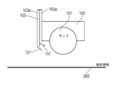
- FIG. 1 is a schematic perspective view of a light irradiation apparatus according to an embodiment.
- FIG. 2 is a schematic side view of one lamp of the light irradiation apparatus according to the embodiment.
- a plurality of circular lamps 101 are arranged.
- the lamp 101 is supported by a lamp holder 102.
- the lamp holder 102 is a member that also serves as an external electrode of the lamp 101. For this reason, the lamp holder 102 is in contact with the lamp 101.
- a plurality of gas supply pipes 103 are provided on the side surface of the lamp holder 102.
- two gas pipes 103a and 103b are provided in the gas supply pipe 103.
- a nozzle is provided as a gas injection section at the tip of each of the gas pipes 103a and 103b (see FIG. 2).
- the nozzles are a first nozzle 110 (first gas injection unit) and a second nozzle 120 (second gas injection unit).
- Each of the first nozzle 110 and the second nozzle 120 preferably has a shape having a slit-like opening continuous in the longitudinal direction of the lamp 101.
- the first nozzle 110 and the second nozzle 120 may be nozzles in which a plurality of openings are arranged in the longitudinal direction of the lamp 101, or a change plate that changes the gas flow. It may be. These nozzle shapes will be described later.
- the gas supply pipes 103 are aggregated and finally connected to a gas supply source (not shown).
- the supplied gas is preferably a gas that does not react with an object to be described later and does not absorb ultraviolet light.
- a gas that does not react with an object to be described later and does not absorb ultraviolet light.
- examples of such a gas include nitrogen gas and inert (such as helium and argon) gas.
- the gas supply source is a gas cylinder of these gases.
- a gas flow meter, a flow rate control valve (both not shown) and the like are arranged in the middle of these.
- a booster pump (not shown) may be provided in the middle of these.
- the first nozzle 110 and the second nozzle 120 are provided in the gas pipes 103 a and 103 b, respectively, but instead of this, one gas pipe is branched immediately before the nozzle and the first nozzle 110 and the second nozzle 120 are provided. Gas may be distributed to the second nozzle 120.
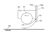
- the light irradiation apparatus 100 is provided with a plurality of rollers 150 for moving (also referred to as conveying) the workpiece 200 under the lamp 101.
- the workpiece 200 is moved in a direction (for example, a vertical direction) that intersects the longitudinal direction of the lamp 101.
- the roller 150 is rotatable and is driven as the workpiece 200 moves.
- the workpiece 200 moves under the lamp 101 when the workpiece 200 is wound up by a winder (not shown). Note that all or some of the plurality of rollers 150 may be connected to a power source and rotate to assist the movement of the workpiece 200.
- the lamp 101 various lamps 101 are used according to the purpose of processing the workpiece 200.
- the lamp 101 to be used is an ultraviolet lamp.
- the lamp shape is tubular or torus (tubular is shown in the drawings of the present embodiment).
- a spherical lamp 101 can be used.
- a shape in which the gas flow from the nozzle is disturbed is not preferable.
- a virtual line connecting the center of the lamp 101 and the workpiece 200 at the shortest distance is set here. This is the reference line.
- the right side in the figure is the first side and the left side is the second side so that the reference line is the center line and the line is symmetrical.
- the first nozzle 110 and the second nozzle 120 are both installed on the same side (here, the first side).
- the installation side may be upstream or downstream in relation to the moving direction of the workpiece 200.
- the first nozzle 110 is installed at a position where the gas (first gas flow) is directly sprayed toward the lamp 101, and the second nozzle 120 directly sprays the gas (second gas flow) toward the workpiece 200. It is installed at the position to attach.
- the second nozzle 120 is provided at a position closer to the workpiece 200 than the first nozzle 110. Thereby, the center of the gas injection direction from the first nozzle 110 and the center of the gas injection direction from the second nozzle 120 do not intersect each other.
- the positional relationship between the first nozzle 110 and the second nozzle 120 and the lamp 101 does not significantly block the light emitted from the lamp 101 in consideration of the size of the first nozzle 110, the second nozzle 120 and the gas supply pipe 103. Install in position.
- the relative speed with respect to the lamp 101 hereinafter simply referred to as the relative speed
- the integrated light quantity (J / cm 2 ) received by the workpiece surface is not nozzle-installed. It is preferable that B / A ⁇ 0.8, where A is the value of A and B is the value after the nozzle is installed.
- the light quantity received by the workpiece 200 is set at a position where 80% or more can be secured when the nozzle is installed compared to when the nozzle is not installed.
- the integrated light quantity does not extremely decrease compared to the case where both nozzles are not installed. For this reason, compared with the case where no nozzle is installed, it is not necessary to take a measure such as lowering the moving speed, and the productivity is not affected.
- imaginary lines are set to represent the gas injection angles of the first nozzle 110 and the second nozzle 120, respectively.
- the imaginary line is a parallel line drawn in parallel with the reference line in the direction of the workpiece 200 from the respective injection ports of the first nozzle 110 and the second nozzle 120.
- a line drawn in parallel to the reference line from the ejection port of the first nozzle 110 in the direction of the workpiece 200 is defined as a first parallel line, and parallel to the reference line in the direction of the workpiece 200 from the ejection port of the second nozzle 120.
- the line drawn to is defined as the second parallel line.
- the angle formed by the gas injection direction of the first nozzle 110 and the first parallel line is ⁇ .
- the angle ⁇ formed is positive in the direction opening from the first parallel line toward the lamp 101.
- This angle ⁇ is the gas injection angle of the first nozzle 110.
- the allowable range of the angle ⁇ is different depending on the size of the lamp 101 and the distance between the lamp 101 and the first nozzle 110. In other words, the allowable range of the angle ⁇ is such that if the size of the lamp 101 is the same, the allowable range of the angle ⁇ increases if the distance between the lamp 101 and the first nozzle 110 is short, and the angle formed if the distance is long.
- the allowable range of ⁇ becomes smaller.
- the gas injection direction center from the first nozzle 110 can be directed toward the lamp 101 if the angle ⁇ is about 60 degrees. If the first nozzle 110 is installed away from the lamp 101, the angle ⁇ may be set to 120 degrees. In such an angle range, the center of the gas injection direction from the first nozzle 110 faces the lamp 101 direction. That is, within such an angle range, the first nozzle 110 is installed at a position that does not block the irradiated light, and the gas ejected from the first nozzle 110 can be directly sprayed toward the lamp 101. it can. Moreover, a laminar flow along the lamp tube surface can be generated.
- the angle between the gas injection direction of the second nozzle 120 and the second parallel line is ⁇ .
- the angle ⁇ formed is positive in the direction from the second parallel line toward the lamp 101.
- This angle ⁇ is the gas injection angle of the second nozzle 120.
- the formed angle ⁇ is preferably more than 0 degree and 90 degrees or less.
- the gas ejected from the second nozzle 120 can be directly sprayed in the direction of the workpiece 200, and the second nozzle 120 can be installed without blocking the irradiated light.
- a laminar flow can be generated between the lamp 101 and the workpiece 200. More preferably, the angle is 20 degrees or more and 90 degrees or less. By setting the angle range, a laminar flow can be generated in the vicinity of the workpiece 200 between the lamp 101 and the workpiece 200.
- the gas flow rate from each nozzle is not particularly limited as long as two gas flows can be generated between the lamp 101 and the workpiece 200. Therefore, if the flow rate is too low, a gas flow cannot be created. On the other hand, if it is unnecessarily too much, there is no meaning because the effect of suppressing lamp contamination with respect to the amount of gas consumption is not improved.
- the gas flow rates of the first nozzle 110 and the second nozzle 120 are about 0.02 to 4.0 (m 3 / min) in terms of 1 m of the light emission effective length (width) of the lamp 101. It is preferable that Note that the gas flow rates of the first nozzle 110 and the second nozzle 120 are preferably set to be the same as much as possible.
- the gas flow rate from one nozzle is too high, the balance is poor and the two gas flows cannot be formed well.
- the other is preferably 50% or more, and more preferably, the gas flow rates of both are the same.
- the first nozzle 110 and the second nozzle 120 are configured to inject gas perpendicular to the longitudinal direction of the lamp 101.
- FIG. 3 is a schematic perspective view for explaining a gas injection port of the nozzle. This figure is a schematic perspective view of the lamp direction as viewed from the workpiece side.
- each of the first nozzle 110 and the second nozzle 120 has one rectangular opening extending over the entire length (light emission effective length) in the lamp longitudinal direction. That is, the shape looks like a slit when only the nozzle outlet is viewed. If the nozzle has such a slit-like opening, the first nozzle 110 can inject gas at a substantially uniform flow rate onto the surface of the lamp tube. Similarly, the second nozzle 120 can inject gas to the object to be processed at a substantially uniform flow rate. Therefore, it is most preferable that the first nozzle 110 and the second nozzle 120 each have one slit-shaped opening.
- the spray diffusion angle (so-called spray angle) in the direction orthogonal to the lamp longitudinal direction of each nozzle does not need to be widened, and about 0 to 45 degrees is sufficient.
- the spray angle in the lamp longitudinal direction gas diffusion at the end in the longitudinal direction of the slit
- the spray angle in the longitudinal direction of the lamp may be about 0 to 45 degrees, for example.
- a plurality of gas pipes 103a and 103b are provided for the first nozzle 110 and the second nozzle 120 having one slit-like opening (see FIG. 1).
- the number of gas pipes 103a and 103b varies depending on the length in the lamp longitudinal direction and is not particularly limited.
- the gas may be ejected at a substantially uniform flow rate by a slit-like opening nozzle using a single gas pipe.
- several to several tens of gas pipes may be used accordingly.
- the variation in the gas flow rate injected from the slit-shaped opening is within a certain range.
- the flow rate at the position with the highest gas flow rate is 100%, it is preferable that the flow rate at the position with the minimum gas flow rate be 50% or more. More preferably, the minimum gas flow rate is 80% or more.
- each nozzle 110 and 120 can be 80% or more when the effective light emission length of the lamp 101 is 100%. preferable. By setting it as such a range, the lamp
- the opening height of each of the nozzles 110 and 120 (in the direction orthogonal to the light emission effective length of the lamp 101) is, for example, 0.05 to 2 mm, preferably 0.1 to 1 mm.
- the 1st nozzle 110 and the 2nd nozzle 120 can inject a gas so that a laminar flow (detailed later) may be produced in a ramp direction and a to-be-processed object direction, respectively.
- FIG. 4 is a schematic perspective view for explaining a gas injection port of another nozzle. This figure is a schematic perspective view of the lamp direction as viewed from the workpiece side.
- the first nozzle 110 and the second nozzle 120 may be composed of a plurality of independent nozzles as shown in FIG. That is, the first nozzle 110 includes nozzles 1101 to 1107, and the second nozzle 120 includes nozzles 1201 to 1207.
- the openings of the nozzles 1101 to 1107 and the nozzles 1201 to 1207 have an elliptical shape in which the longitudinal direction of the lamp 101 has a major axis.
- the number of nozzles 1101 to 1107 and nozzles 1201 to 1207 may be set so that gas can be injected at a substantially uniform flow rate over the effective light emission length. For this reason, as in the case of the slit shape, the plurality of nozzles 1101 to 1107 and the nozzles 1201 to 1207 are installed so that gas can be sprayed to 80% or more of the effective light emission length of the lamp 101. Also, in this case, the variation in the flow rate of the injected gas is 50% or more even at the position where the gas flow rate is the minimum, for example, when the flow rate at the position where the gas flow rate is the highest is 100%, as in the case of the slit shape. It is preferable to do so. More preferably, the minimum gas flow rate is 80% or more.
- the gas injection diffusion angle (spray angle) of each nozzle in the nozzles 1101 to 1107 and the nozzles 1201 to 1207 is, for example, slightly widened in the lamp longitudinal direction. Thereby, the variation in the gas flow rate is suppressed.
- the spray angle of each nozzle is preferably about 5 to 120 degrees. Thereby, gas can be injected at a substantially uniform flow rate over the entire length of the light emission effective length of the lamp 101.
- the spray angle in the direction crossing the lamp longitudinal direction is sufficient to be about 0 to 45 degrees as in the case of the slit shape.
- each nozzle showed the case of the ellipse here, you may make it have circular or a rectangular opening, for example.
- FIG. 5 is a side view showing an example using a gas flow direction changing plate for changing the direction of gas flow.
- gas pipes 103a and 103b are provided.
- the gas pipes 103a and 103b are both straight pipes and have openings in the direction of the object to be processed (downward direction in the figure).
- a first gas flow direction changing plate 111 is provided at the opening of the gas pipe 103a
- a second gas flow direction changing plate 121 is provided at the opening of the gas pipe 103b.
- the first gas flow direction changing plate 111 is a first gas injection unit
- the second gas flow direction changing plate 121 is a second gas injection unit.
- the first gas flow direction changing plate 111 changes the direction in which the gas from the gas pipe 103a is directly sprayed onto the lamp 101.
- the first gas flow direction changing plate 111 can directly spray the gas from the gas pipe 103a onto the lamp 101 by attaching a plate-like member at the same angle as that of the first nozzle 110.
- the second gas flow direction changing plate 121 changes the direction in which the gas from the gas pipe 103 b is directly sprayed onto the workpiece 200.
- the second gas flow direction changing plate 121 can spray the gas from the gas pipe 103 b directly onto the workpiece 200 by attaching a plate-like member at the same angle as that of the second nozzle 120.
- the first gas flow direction change plate 111 and the second gas flow direction change plate 121 have a plurality of gas pipes 103 a provided in the longitudinal direction of the lamp 101, and a single first gas flow direction in the longitudinal direction. It is preferable to provide a single second gas flow direction changing plate 121 in the longitudinal direction with respect to the changing plate 111, similarly to a plurality of gas pipes 103b provided in the longitudinal direction of the lamp 101. As a result, the gas can be injected at a substantially uniform flow rate over the entire length of the effective light emission length of the lamp 101.
- first gas flow direction changing plate 111 and the second gas flow direction changing plate 121 may be provided in the gas pipes 103a and 103b, respectively.
- first gas flow direction changing plate 111 and the second gas flow direction changing plate 121 are provided so that the gas can be injected at a substantially uniform flow rate over the entire length of the light emission effective length of the lamp 101.
- FIG. 5 is drawn so that the first gas flow direction changing plate 111 and the second gas flow direction changing plate 121 come to positions opposite to those in FIG. 2.
- the first gas flow direction changing plate 111 and the second gas flow direction changing plate 121 may be arranged on either side of the lamp 101.
- the first nozzle 110 and the second nozzle 120 described above may be arranged on either side of the lamp 101 in the same manner.
- each gas injection portion may be any shape as long as the gas can be injected at a substantially uniform flow rate over the entire length of the effective light emission length. , Not limited.
- FIG. 6 is a side view for explaining the action of the nozzle. The same effect is obtained when a gas flow direction changing plate is used.
- the first nozzle 110 generates a laminar flow (first gas flow indicated by an arrow a) in the vicinity of the surface of the lamp tube by spraying gas directly onto the lamp 101.
- the first gas flow a excludes sublimates (including other scattered matter, the same applies hereinafter) that has arrived near the lamp tube surface from the vicinity of the lamp tube surface, and suppresses adhesion to the lamp tube surface.
- the second nozzle 120 generates a laminar flow (second gas flow indicated by an arrow b) in the vicinity of the surface of the workpiece 200 by spraying gas directly toward the workpiece 200.
- This second gas flow b quickly blows up the sublimate that has risend and suppresses flying near the lamp.
- the gas ejected by the second nozzle 120 will soar the sublimate from the surface of the workpiece 200, but the sublimate remarkablyd by spraying from one direction flows in a certain direction. Can be eliminated.
- the laminar flow by the first nozzle 110 prevents adhesion to the lamp tube surface.
- the object 200 in the present embodiment is a sheet-like, band-like, or plate-like member containing a silicon oxide precursor or silicon oxynitride precursor that is cured by, for example, ultraviolet irradiation on a substrate.
- a silicon oxide precursor or silicon oxynitride precursor that is cured by, for example, ultraviolet irradiation on a substrate.
- An example of such a member is a gas barrier film.
- the gas barrier film is modified by applying a silicon oxide precursor or silicon oxynitride precursor on the film substrate, and curing the silicon oxide precursor or silicon oxynitride precursor by UV irradiation. Thus, a gas barrier effect is imparted.
- Gas barrier films are widely used in electronic devices such as organic EL elements, liquid crystal display elements (LCD), thin film transistors, touch panels, electronic paper, solar cells (PV), and the like.
- the film substrate used for the gas barrier film examples include a metal substrate such as silicon, a glass substrate, a ceramic substrate, and a plastic film, and a plastic film is preferably used.
- the plastic film to be used is not particularly limited in material, thickness and the like as long as it can hold a gas barrier film, a hard coat layer and the like, and can be appropriately selected according to the purpose of use.
- Specific examples of the plastic film include polyester resin, methacrylic resin, methacrylic acid-maleic acid copolymer, polystyrene resin, transparent fluororesin, polyimide, fluorinated polyimide resin, polyamide resin, polyamideimide resin, and polyetherimide.
- Resin cellulose acylate resin, polyurethane resin, polyetheretherketone resin, polycarbonate resin, alicyclic polyolefin resin, polyarylate resin, polyethersulfone resin, polysulfone resin, cycloolefin copolymer, fluorene ring-modified polycarbonate resin, alicyclic ring
- thermoplastic resins such as modified polycarbonate resins, fluorene ring-modified polyester resins, and acryloyl compounds.
- the film substrate is preferably made of a heat resistant material. Specifically, a resin film substrate having a linear expansion coefficient of 15 ppm / K or more and 100 ppm / K or less and a glass transition temperature (Tg) of 100 ° C. or more and 300 ° C. or less is used.
- Tg glass transition temperature
- the resin film substrate satisfies the requirements for use as a laminated film for electronic parts and displays.
- the gas barrier film may be exposed to a process of 150 ° C. or higher.
- the linear expansion coefficient of the film base material in the gas barrier film exceeds 100 ppm / K, the substrate dimensions are not stable when the gas barrier film is passed through the temperature process as described above, and the thermal expansion and contraction occur. Inconvenience that the shut-off performance is deteriorated and inconvenience of being unable to withstand the heat process are likely to occur. If it is less than 15 ppm / K, the film may break like glass and the flexibility may deteriorate.
- Polyolefin for example, ZEONOR (registered trademark) 1600: 160 ° C) manufactured by Nippon Zeon Co., Ltd., polyarylate (PAr: 210 ° C), polyethersulfone (PES: 220 ° C), polysulfone (PSF: 190 ° C), cycloolefin Copolymer (COC: Compound described in JP-A No. 2001-150584: 162 ° C.), polyimide (for example, Neoprim (registered trademark): 260 ° C. manufactured by Mitsubishi Gas Chemical Co., Inc.), fluorene ring-modified polycarbonate (BCF-PC: special Open 2000-227 No.
- gas barrier films are used in combination with polarizing plates.
- the gas barrier film of the gas barrier film is arranged so as to face the inside of the cell, and arranged on the innermost side (adjacent to the element).
- the retardation value of the gas barrier film is important.
- the usage form of the gas barrier film in such an embodiment is as follows: a gas barrier film using a film substrate having a retardation value of 10 nm or less and a circularly polarizing plate (1 ⁇ 4 wavelength plate + (1/2 wavelength plate) + straight line. It is preferable to use a linear polarizing plate in combination with a gas barrier film using a film substrate having a retardation value of 100 nm to 180 nm, which can be used as a quarter wavelength plate. .
- Examples of the film substrate having a retardation of 10 nm or less include, for example, cellulose triacetate (Fuji Film Co., Ltd .: Fujitac (registered trademark)), polycarbonate (Teijin Chemicals Co., Ltd .: Pure Ace (registered trademark), Kaneka Corporation): Elmec (registered trademark)), cycloolefin polymer (manufactured by JSR Corporation: Arton (registered trademark), Nippon Zeon Corporation: ZEONOR (registered trademark)), cycloolefin copolymer (manufactured by Mitsui Chemicals, Inc .: APPEL (registered trademark)) (Pellets), manufactured by Polyplastics Co., Ltd .: Topas (registered trademark) (pellets)), polyarylate (manufactured by Unitika Co., Ltd .: U100 (pellets)), transparent polyimide (manufactured by Mitsubishi Gas Chemical Co., Ltd .
- a film base material adjusted to a desired retardation value by appropriately stretching the above film base material can be used.
- the plastic film is preferably transparent. That is, the light transmittance is usually 80% or more, preferably 85% or more, and more preferably 90% or more.
- the light transmittance is calculated by measuring the total light transmittance and the amount of scattered light using the method described in JIS K7105: 1981, that is, using an integrating sphere light transmittance measuring device, and subtracting the diffuse transmittance from the total light transmittance. can do.
- an opaque material can be used as the plastic film. Examples of the opaque material include polyimide, polyacrylonitrile, and known liquid crystal polymers.
- the thickness of the plastic film used as the base material of the gas barrier film is not particularly limited because it is appropriately selected depending on the use, but is typically 1 to 800 ⁇ m, preferably 10 to 200 ⁇ m.
- These plastic films may have functional layers such as a transparent conductive layer and a primer layer.
- As the functional layer in addition to those described above, those described in paragraph numbers 0036 to 0038 of JP-A-2006-289627 can be preferably employed.
- the substrate preferably has a high surface smoothness.
- the surface smoothness those having an average surface roughness (Ra) of 2 nm or less are preferable. Although there is no particular lower limit, it is practically 0.01 nm or more. If necessary, both surfaces of the base material, at least the side on which the gas barrier film is provided, may be polished to improve smoothness.
- the base material using the above-described resins or the like may be an unstretched film or a stretched film.
- silicon oxide precursors or silicon oxynitride precursors include, for example, perhydropolysilazane, organopolysilazane, silsesquioxane, tetramethylsilane, and trimethylmethoxysilane.
- polysilazanes such as perhydropolysilazane and organopolysilazane; polysiloxanes such as silsesquioxane, and the like are preferable in terms of film formation, fewer defects such as cracks, and less residual organic matter.
- Polysilazane is more preferable, and perhydropolysilazane is particularly preferable because the performance is high and the barrier performance is maintained even when bent and under high temperature and high humidity conditions.
- Polysilazane is a polymer having a silicon-nitrogen bond, having a bond such as Si—N, Si—H, and N—H, and a precursor such as SiO 2 , Si 3 N 4 , and both intermediate solid solutions SiOxNy, etc. It is an inorganic polymer that becomes the body.
- the polysilazane preferably has the following structure.
- R 1 , R 2 and R 3 are each independently a hydrogen atom, a substituted or unsubstituted alkyl group, aryl group, vinyl group or (trialkoxysilyl) alkyl group. .
- R 1 , R 2 and R 3 may be the same or different.
- examples of the alkyl group include linear, branched or cyclic alkyl groups having 1 to 8 carbon atoms.
- the aryl group include aryl groups having 6 to 30 carbon atoms.
- non-condensed hydrocarbon groups such as phenyl group, biphenyl group, terphenyl group; pentarenyl group, indenyl group, naphthyl group, azulenyl group, heptaenyl group, biphenylenyl group, fluorenyl group, acenaphthylenyl group, preadenenyl group , Condensed polycyclic hydrocarbon groups such as acenaphthenyl group, phenalenyl group, phenanthryl group, anthryl group, fluoranthenyl group, acephenanthrenyl group, aceantrirenyl group, triphenylenyl group, pyrenyl group, chrysenyl group, naphthacenyl group, etc.
- non-condensed hydrocarbon groups such as phenyl group, biphenyl group, terphenyl group; pentarenyl group, indenyl group, nap
- the (trialkoxysilyl) alkyl group includes an alkyl group having 1 to 8 carbon atoms having a silyl group substituted with an alkoxy group having 1 to 8 carbon atoms. More specific examples include 3- (triethoxysilyl) propyl group and 3- (trimethoxysilyl) propyl group.
- the substituent optionally present in R 1 to R 3 is not particularly limited, and examples thereof include an alkyl group, a halogen atom, a hydroxyl group (—OH), a mercapto group (—SH), a cyano group (—CN), There are a sulfo group (—SO 3 H), a carboxyl group (—COOH), a nitro group (—NO 2 ) and the like. Note that the optionally present substituent is not the same as R 1 to R 3 to be substituted. For example, when R 1 to R 3 are alkyl groups, they are not further substituted with alkyl groups.
- R 1 , R 2 and R 3 are preferably a hydrogen atom, a methyl group, an ethyl group, a propyl group, an isopropyl group, a butyl group, an isobutyl group, a tert-butyl group, a phenyl group, a vinyl group, 3 -(Triethoxysilyl) propyl group or 3- (trimethoxysilylpropyl) group.
- n is an integer
- the polysilazane having the structure represented by the general formula (I) is determined to have a number average molecular weight of 150 to 150,000 g / mol. preferable.
- one of preferred embodiments is perhydropolysilazane in which all of R 1 , R 2 and R 3 are hydrogen atoms.
- polysilazane has a structure represented by the following general formula (II).
- R 1 ′ , R 2 ′ , R 3 ′ , R 4 ′ , R 5 ′ and R 6 ′ are each independently a hydrogen atom, a substituted or unsubstituted alkyl group, An aryl group, a vinyl group or a (trialkoxysilyl) alkyl group.
- R 1 ′ , R 2 ′ , R 3 ′ , R 4 ′ , R 5 ′ and R 6 ′ may be the same or different.
- the substituted or unsubstituted alkyl group, aryl group, vinyl group or (trialkoxysilyl) alkyl group in the above is the same as the definition of the general formula (I), and thus the description is omitted.
- n ′ and p are integers, and the polysilazane having the structure represented by the general formula (II) is determined to have a number average molecular weight of 150 to 150,000 g / mol. It is preferred that Note that n ′ and p may be the same or different.
- R 1 ′ , R 3 ′ and R 6 ′ each represent a hydrogen atom, and R 2 ′ , R 4 ′ and R 5 ′ each represent a methyl group;
- R 1 ' , R 3' and R 6 ' each represents a hydrogen atom, R 2' , R 4 ' each represents a methyl group, and R 5' represents a vinyl group;
- R 1 ' , R 3' , R 4 A compound in which ' and R 6' each represent a hydrogen atom and R 2 ' and R 5' each represents a methyl group is preferred.
- polysilazane has a structure represented by the following general formula (III).
- R 1 ′′ , R 2 ′′ , R 3 ′′ , R 4 ′′ , R 5 ′′ , R 6 ′′ , R 7 ′′ , R 8 ′′ and R 9 ′′ are each independently A hydrogen atom, a substituted or unsubstituted alkyl group, aryl group, vinyl group or (trialkoxysilyl) alkyl group, wherein R 1 ′′ , R 2 ′′ , R 3 ′′ , R 4 ′′ , R 5 ′′ , R 6 ′′ , R 7 ′′ , R 8 ′′ and R 9 ′′ may be the same or different.
- the substituted or unsubstituted alkyl group, aryl group, vinyl group or (trialkoxysilyl) alkyl group in the above is the same as the definition of the general formula (I), and thus the description is omitted.
- n ′′, p ′′ and q are integers, and the polysilazane having the structure represented by the general formula (III) has a number average molecular weight of 150 to 150,000 g / mol. It is preferable to be determined as follows. Note that n ′′, p ′′, and q may be the same or different.
- R 1 ′′ , R 3 ′′ and R 6 ′′ each represent a hydrogen atom
- R 2 ′′ , R 4 ′′ , R 5 ′′ and R 8 ′′ each represent a methyl group.
- R 9 ′′ represents a (triethoxysilyl) propyl group
- R 7 ′′ represents an alkyl group or a hydrogen atom.
- the organopolysilazane in which a part of the hydrogen atom portion bonded to Si is substituted with an alkyl group or the like has improved adhesion to the base material as a base by having an alkyl group such as a methyl group and is hard.
- the ceramic film made of brittle polysilazane can be toughened, and there is an advantage that the occurrence of cracks can be suppressed even when the (average) film thickness is increased. For this reason, perhydropolysilazane and organopolysilazane may be selected as appropriate according to the application, and may be used in combination.
- Perhydropolysilazane is presumed to have a linear structure and a ring structure centered on 6- and 8-membered rings.
- the number average molecular weight (Mn) is about 600 to 2000 (polystyrene conversion), and there are liquid or solid substances, and the state varies depending on the molecular weight.
- polysilazane examples include, but are not limited to, for example, silicon alkoxide-added polysilazane obtained by reacting the above polysilazane with silicon alkoxide (Japanese Patent Laid-Open No.
- glycidol addition obtained by reacting glycidol Polysilazane (JP-A-6-122852), alcohol-added polysilazane obtained by reacting an alcohol (JP-A-6-240208), metal carboxylate-added polysilazane obtained by reacting a metal carboxylate 6-299118), acetylacetonate complex-added polysilazane obtained by reacting a metal-containing acetylacetonate complex (JP-A-6-306329), metal fine particle-added polysilazane obtained by adding metal fine particles (specialty) Kaihei 7 Publication), etc.
- No. 196,986 include polysilazane ceramic at low temperatures.
- the precursor as described above is prepared as a coating liquid for forming a coating film (hereinafter also referred to as a coating liquid for forming a coating film).
- the solvent used for the preparation is not particularly limited as long as it can dissolve the precursor, but does not include water and reactive groups (for example, hydroxyl group or amine group) that easily react with the precursor.
- An organic solvent inert to the precursor is preferable, and an aprotic organic solvent is more preferable.
- an aprotic solvent for example, carbonization of aliphatic hydrocarbons, alicyclic hydrocarbons, aromatic hydrocarbons such as pentane, hexane, cyclohexane, toluene, xylene, solvesso, turben, etc.
- Hydrogen solvents Halogen hydrocarbon solvents such as methylene chloride and trichloroethane; Esters such as ethyl acetate and butyl acetate; Ketones such as acetone and methyl ethyl ketone; Aliphatic ethers such as dibutyl ether, dioxane and tetrahydrofuran; Alicyclic ethers and the like Ethers: Examples include tetrahydrofuran, dibutyl ether, mono- and polyalkylene glycol dialkyl ethers (diglymes), and the like.
- the solvent is selected according to purposes such as the solubility of the precursor and the evaporation rate of the solvent, and may be used alone or in the form of a mixture of two or more.
- the concentration of the precursor in the coating solution for coating film formation is not particularly limited, and varies depending on the film thickness of the gas barrier film and the pot life of the coating solution, but is preferably 1 to 80% by weight, more preferably 5 to 50% by weight. More preferably, it is 10 to 40% by weight.
- the coating liquid for forming a coating film preferably contains a catalyst in order to promote reforming.
- catalysts include N, N-diethylethanolamine, N, N-dimethylethanolamine, triethanolamine, triethylamine, 3-morpholinopropylamine, N, N, N ′, N′-tetramethyl- 1,3-diaminopropane, amine compounds such as N, N, N ′, N′-tetramethyl-1,6-diaminohexane, Pt compounds such as Pt acetylacetonate, Pd compounds such as propionic acid Pd, Rh acetyl Metal catalysts such as Rh compounds such as acetonate, N-heterocyclic compounds, pyridine compounds such as pyridine, ⁇ -picoline, ⁇ -picoline, ⁇ -picoline, piperidine, lutidine, pyrimidine, pyridazine, DBU (1,8- Diazabicyclo [
- the concentration of the catalyst added at this time is preferably in the range of 0.1 to 10% by weight, more preferably 0.5 to 7% by weight, based on polysilazane. By setting the addition amount of the catalyst within this range, it is possible to avoid excessive silanol formation due to rapid progress of the reaction, decrease in film density, increase in film defects, and the like.
- the following additives can be used as necessary.
- cellulose ethers, cellulose esters for example, ethyl cellulose, nitrocellulose, cellulose acetate, cellulose acetobutyrate, etc.
- natural resins for example, rubber, rosin resin, etc., synthetic resins
- Aminoplasts especially urea resins, melamine formaldehyde resins, alkyd resins, acrylic resins, polyesters or modified polyesters, epoxides, polyisocyanates or blocked polyisocyanates, polysiloxanes, and the like.
- a conventionally known appropriate wet coating method can be employed as a method of applying the coating liquid for forming a coating film.
- a spin coating method a roll coating method, a flow coating method, an ink jet method, a spray coating method, a printing method, a dip coating method, a casting film forming method, a bar coating method, and a gravure printing method.
- the coating thickness can be appropriately set according to the purpose.
- the coating thickness per gas barrier film is preferably about 5 to 500 nm, more preferably 10 to 400 nm after drying. If the film thickness is 5 nm or more, sufficient barrier properties can be obtained, and if it is 500 nm or less, stable coating properties can be obtained at the time of coating film formation, and high light transmittance can be realized.
- the coating film After applying the coating solution, it is preferable to dry the coating film.
- the organic solvent contained in the coating film can be removed. At this time, all of the organic solvent contained in the coating film may be dried or may be partially left. Even when a part of the organic solvent is left, a suitable gas barrier film can be obtained. The remaining solvent can be removed later.
- the drying temperature of the coating film varies depending on the substrate to be applied, but is preferably 50 to 200 ° C.
- the drying temperature is preferably set to 150 ° C. or less in consideration of deformation of the substrate due to heat.
- the temperature can be set by using a hot plate, oven, furnace or the like.
- the drying time is preferably set to a short time. For example, when the drying temperature is 150 ° C., the drying time is preferably set within 30 minutes.
- the drying atmosphere may be any condition such as an air atmosphere, a nitrogen atmosphere, an argon atmosphere, a vacuum atmosphere, or a reduced pressure atmosphere with a controlled oxygen concentration.
- the coating film obtained by applying the coating solution for forming the upper coating film may include a step of removing moisture before or during the modification treatment.
- a form of dehumidification while maintaining a low humidity environment is preferable. Since humidity in a low-humidity environment varies depending on temperature, a preferable form is shown for the relationship between temperature and humidity by defining the dew point temperature.
- the preferable dew point temperature is 4 ° C. or less (temperature 25 ° C./humidity 25%), the more preferable dew point temperature is ⁇ 5 ° C. (temperature 25 ° C./humidity 10%) or less, and the maintaining time depends on the film thickness of the gas barrier film. It is preferable to set appropriately.
- the dew point temperature is ⁇ 5 ° C. or less and the maintaining time is 1 minute or more.
- the lower limit of the dew point temperature is not particularly limited, but is usually ⁇ 50 ° C. or higher, and preferably ⁇ 40 ° C. or higher. This is a preferred form from the viewpoint of promoting the dehydration reaction of the gas barrier film by removing water before or during the reforming process.
- Polysilazane which is a preferred precursor, is commercially available in a solution state dissolved in an organic solvent, and a commercially available product can be used as it is as a coating solution for coating film formation.
- examples of commercially available polysilazane solutions include NN120-10, NN120-20, NAX120-20, NN110, NN310, NN320, NL110A, NL120A, NL120-20, NL150A, NP110, NP140, and SP140 manufactured by Merck Performance Materials. Can be mentioned.
- the irradiation is performed by irradiating ultraviolet rays using the light irradiation apparatus according to the present embodiment.
- light energy having a wavelength component of less than 200 nm, which is larger than the interatomic bonding force in silicon oxide or silicon oxynitride, and preferably using ultraviolet light containing a wavelength component of 100 to 180 nm is used for photon process of bonding atoms.
- a silicon oxide film and / or silicon oxynitride film is formed at a relatively low temperature (about 200 ° C. or less) by causing an oxidation reaction with active oxygen or ozone to proceed while cutting directly by the action of photons only. I do.
- any light source that generates ultraviolet light including a wavelength component of less than 200 nm may be used.
- Excimer radiators eg, excimer lamps such as Xe excimer lamps having maximum emission at about 172 nm, ArF excimer lamps having maximum emission at about 193 nm, ArBr excimer lamps having maximum emission at about 161 nm
- a low-pressure mercury lamp, an amalgam lamp, a deuterium lamp, or a lamp using carbon monoxide having strong emission lines at about 156 nm and about 165 nm is used.
- a rare gas excimer lamp is particularly preferably used. Since noble gas atoms such as Xe, Kr, Ar, Ne, and the like are chemically bonded and do not form molecules, they are called inert gases. However, rare gas atoms (excited atoms) that have gained energy by discharge or the like can be combined with other atoms to form molecules. When the rare gas is xenon, e + Xe ⁇ e + Xe * Xe * + Xe + Xe ⁇ Xe 2 * + Xe, and excimer light of 172 nm is emitted when the excited excimer molecule Xe 2 * transitions to the ground state.
- ⁇ Excimer lamps are characterized by high efficiency because radiation concentrates on one wavelength and almost no other light is emitted. Further, since no extra light is emitted, the temperature of the object can be kept low. Furthermore, since no time is required for starting and restarting, instantaneous lighting and blinking are possible.
- Dielectric barrier discharge is a lightning generated in a gas space by arranging a gas space between both electrodes via a dielectric (transparent quartz in the case of an excimer lamp) and applying a high frequency high voltage of several tens of kHz to the electrode.
- the discharge is called a micro discharge (micro discharge) similar to the above.
- the micro discharge streamer reaches the tube wall (dielectric)
- the electric charge accumulates on the dielectric surface, and the micro discharge disappears.
- This micro discharge spreads over the entire tube wall and repeats generation and extinction. For this reason, flickering of light that can be seen with the naked eye occurs.
- a very high temperature streamer reaches a pipe wall directly locally, there is a possibility that deterioration of the pipe wall may be accelerated.
- electrodeless field discharge is possible in addition to dielectric barrier discharge.
- Electrode-free electric field discharge by capacitive coupling also called high frequency discharge (RF (Radio Frequency) discharge.
- the lamp 101, the electrodes, and their arrangement may be basically the same as those of the dielectric barrier discharge, but the high frequency applied between the two electrodes is lit at several MHz. Since the electrodeless field discharge can obtain a spatially and temporally uniform discharge in this way, a long-life lamp 101 without flickering can be obtained.
- the outer electrode covers the entire outer surface and allows light to pass through to extract light to the outside in order to cause discharge in the entire discharge space.
- an electrode in which a fine metal wire is formed in a net shape is used. Since this electrode uses as thin a line as possible so as not to block light, it is easily damaged by ozone generated by vacuum ultraviolet light in an oxygen atmosphere.
- Synthetic quartz windows are not only expensive consumables, but also cause light loss.
- the outer diameter of the double-cylindrical lamp is about 25 mm, the difference in distance to the irradiation surface cannot be ignored directly below the lamp axis and on the side of the lamp, resulting in a large difference in illuminance. Therefore, even if the lamps 101 are arranged in close contact, a uniform illuminance distribution cannot be obtained. If the irradiation device is provided with a synthetic quartz window, the distance in the oxygen atmosphere can be made uniform, and a uniform illuminance distribution can be obtained.
- the synthetic quartz window is the lamp tube surface. Therefore, if it is contaminated with sublimates, the synthetic quartz window must be cleaned or replaced.
- the biggest feature of the capillary excimer lamp is its simple structure.
- the quartz tube is closed at both ends, and only gas for excimer light emission is sealed inside. Therefore, a very inexpensive light source can be provided.
- Double-cylindrical lamps are easily damaged by handling and transportation compared to thin-tube lamps because they are processed by connecting both ends of the inner and outer tubes.
- the outer diameter of the tube of the thin tube lamp is about 6 to 12 mm. If it is too thick, a high voltage is required for starting.
- the discharge mode can be either dielectric barrier discharge or electrodeless field discharge.
- the electrode may have a flat surface in contact with the lamp 101, but if the shape is matched to the curved surface of the lamp 101, the lamp 101 can be firmly fixed, and the discharge is more stable when the electrode is in close contact with the lamp 101. To do. Also, if the curved surface is made into a mirror surface with aluminum, it also becomes a light reflector.
- the Xe excimer lamp emits ultraviolet light having a short wavelength of 172 nm at a single wavelength, and thus has excellent luminous efficiency. Since this light has a large oxygen absorption coefficient, radical oxygen atomic species and ozone can be generated at a high concentration with a small amount of oxygen.
- the energy of light having a short wavelength of 172 nm has a high ability to dissociate organic bonds.
- the coating film can be modified in a short time by the high energy of the active oxygen, ozone and ultraviolet radiation.
- ⁇ Excimer lamps have high light generation efficiency and can be lit with low power.
- light having a long wavelength that causes a temperature increase due to light is not emitted, and energy is irradiated in the ultraviolet region, that is, in a short wavelength, so that the increase in the surface temperature of the target object is suppressed.
- it is suitable for flexible film materials such as PET that are easily affected by heat.
- the lamp 101 by these dielectric barrier discharge or electrodeless electric field discharge is preferably used.
- Oxygen is required for the reaction at the time of irradiation, but ultraviolet light containing a wavelength component of 200 nm or less is easily absorbed because it is absorbed by oxygen. Therefore, irradiation is performed with oxygen concentration and water vapor concentration as much as possible. It is preferable to carry out in a low state. That is, the oxygen concentration during irradiation is preferably 0.01 to 5% by volume, more preferably 0.01 to 1% by volume, and further preferably 0.01 to 0.5% by volume. preferable.
- a dry inert gas is preferable, and a dry nitrogen gas is particularly preferable from the viewpoint of cost.
- the oxygen concentration can be adjusted by measuring the flow rates of oxygen gas and inert gas introduced into the irradiation chamber and changing the flow rate ratio. In order to satisfy these conditions, in the apparatus of this embodiment, it is preferable to spray dry nitrogen gas from the first nozzle 110 and the second nozzle 120 while maintaining the oxygen concentration of the atmosphere in the apparatus within the above range.
- the peak illuminance of ultraviolet light on the coating surface that the coating film receives is preferably 50 to 500 mW / cm 2 , and more preferably 80 to 300 mW / cm 2 . If it is this range, modification
- the irradiation energy amount (irradiation amount) of ultraviolet light on the coating surface is preferably 0.01 to 20 J / cm 2 , more preferably 0.1 to 20 J / cm 2 , and 0.3 to 15 J. More preferably, it is / cm 2 . If it is this range, hardening will fully advance and productivity will improve. In addition, it is possible to prevent cracks due to excessive modification and thermal deformation of the film substrate.
- an ultraviolet irradiation process may be performed in multiple times, what is necessary is just to select the irradiation amount per time suitably so that the sum total of irradiation amount may become the said range.
- the distance between the film substrate and the ultraviolet light source and the irradiation time so long as the film substrate carrying the irradiated coating film is not damaged.
- the distance between the substrate and the ultraviolet irradiation lamp is preferably 0.01 to 10 mm from the viewpoint of suppressing light absorption by oxygen.
- the irradiation time is preferably 0.05 to 300 seconds from the viewpoint of reforming efficiency and productivity.
- ultraviolet light having a wavelength of 200 nm or more and less than 230 nm may be used for ultraviolet irradiation.
- the ultraviolet light source having such a wavelength is not limited as long as it generates ultraviolet light having a wavelength of 200 nm or more and less than 230 nm.
- a KrCl excimer lamp single wavelength of 222 nm
- a KrBr excimer lamp 207 nm
- AlGaN Although the LED element etc. which used AlN are mentioned, it is not specifically limited.
- a phosphor is provided inside the glass tube of the Xe excimer lamp (for example, Japanese Patent Application Laid-Open No. 2011-175823), or ultraviolet light having the wavelength is generated through a filter provided with a phosphor between the Xe excimer lamp and the coating film. Can do.
- oxygen is required, and the oxygen concentration at the time of irradiation is preferably 0.01 to 21% by volume, more preferably 0.1 to 21% by volume. If it is this range, the modification
- the gas satisfying the irradiation atmosphere is preferably a dry inert gas, and particularly preferably a dry nitrogen gas from the viewpoint of cost.
- the oxygen concentration can be adjusted by measuring the flow rates of oxygen gas and inert gas introduced into the irradiation chamber and changing the flow rate ratio.
- the dry nitrogen gas is supplied to the first nozzle 110 and the second nozzle while maintaining the oxygen concentration in the atmosphere in the apparatus in the above range. It may be sprayed from the nozzle 120.
- the peak illuminance of the ultraviolet light on the coating surface received by the coating film is preferably 10 to 500 mW / cm 2 , more preferably 50 to 300 mW / cm 2. preferable. If it is this range, hardening will be attained to the deep part of a coating film. Further, the irradiation energy amount (irradiation amount) of ultraviolet light on the coating surface is preferably 0.01 to 20 J / cm 2 , more preferably 0.1 to 15 J / cm 2 , and 0.3 More preferably, it is ⁇ 10 J / cm 2 . If it is this range, hardening will fully advance and productivity will improve.
- the ultraviolet irradiation may be performed a plurality of times.
- the irradiation amount per time may be appropriately selected so that the total irradiation amount falls within the above range.
- the distance between the substrate and the ultraviolet irradiation lamp is preferably 0.01 to 100 mm from the viewpoint of suppressing light absorption by oxygen.
- the irradiation time is preferably 0.05 to 300 seconds from the viewpoint of reforming efficiency and productivity.
- the distance between the lamp 101, which is an ultraviolet light source, and the workpiece 200 may be set so as to be the above-mentioned ultraviolet irradiation energy, and is not particularly limited, but is preferably 5 to 50 mm, for example.
- the lamps 101 are installed at regular intervals (for example, at intervals of 5 to 200 mm) in the moving direction of the workpiece 200. At this time, the number of lamps 101 installed differs depending on the relative speed with the workpiece 200. If the lamp illuminance is the same, if the number of lamps 101 is small, the relative speed is slowed down, which is necessary for curing. When the number of lamps 101 is large, the throughput can be increased by increasing the relative speed.
- a light irradiation device with one excimer lamp was used.
- the workpiece was moved relative to the excimer lamp.
- the workpiece was moved by a roll-to-roll method.
- the structure of a light irradiation apparatus and a to-be-processed object is as follows.
- the light irradiation device has a water-cooled excimer lamp manufactured by M.D.
- the excimer lamp has an outer diameter of 20 mm ⁇ and an effective irradiation width of 500 mm.
- the tube surface illuminance was adjusted to a range of 120 ⁇ 5 mW / cm 2 at a distance of 3 mm from the tube surface of the lamp (the gap was filled with nitrogen).
- the gas injection nozzle has a slit-like (rectangular) injection port in which both the first nozzle and the second nozzle have an injection port opening of 0.5 mm in height and 500 mm in length.
- the gas used is nitrogen gas.
- the base material of the object to be processed was a PET base material (UH13 manufactured by Toray Industries Inc.) having a width of 550 mm and a thickness of 100 ⁇ m.
- polysilazane manufactured by Merck Performance Materials, NN120 was prepared by diluting to 5% by mass with dibutyl ether.
- the substrate was moved at a speed of 0.5 m / min, and an application liquid was applied to the smooth surface side of the substrate so that the dry film thickness was 100 nm using an extrusion coater.
- the application width is 500 mm. This moving speed is a condition in which, after coating, drying is performed at 50 ° C. for 10 minutes in the first drying section and then drying at 80 ° C. for 10 minutes in the second drying section.
- Nitrogen is supplied to the chamber of the light irradiation device, and the oxygen concentration in the space between the lamp tube surface and the substrate coating surface is controlled to be maintained in the range of 0.05 to 0.1% by volume. Ultraviolet irradiation was performed. At this time, the arrangement of the nozzles and the nitrogen gas flow rate were changed, and a continuous treatment of 500 m was performed so as to be an example and a comparative example. In each example and comparative example, a new lamp was used at the start.
- Lamp tube surface illuminance measurement The tube surface illuminance before and after 500 m continuous treatment was measured as follows.
- the illuminance at a distance of 3 mm from the tube surface of the lamp is measured before and after 500 m continuous processing, and the illuminance after continuous processing when the illuminance before continuous processing is taken as 100 is lamp contamination. It was used as an index.
- the illuminance was measured at a total of three points 200 mm away from the center of the lamp and left and right from the center of the lamp, and the average value of the three points was taken as the illuminance. Each measurement was performed on the portion of the lamp tube surface closest to the workpiece.
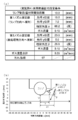
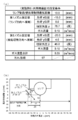
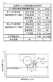
- FIGS. 7 to 26 are explanatory diagrams for explaining each example and comparative example.
- (a) is a chart showing the setting conditions and the result of the dirt index
- (b) is a workpiece. It is a figure which shows the arrangement
- the setting conditions shown in the chart of (a) are the distance between the lamp and the workpiece, the nozzle setting values (position and injection angle), and the gas flow rate.
- the position closest to the workpiece on the lamp tube surface is shown to be the origin (zero) of the two-dimensional coordinates.
- Table 1 summarizes the setting conditions of each example and comparative example and the results of the lamp contamination index.
- the setting condition outline is an outline of the setting conditions shown in FIGS. 7 to 26.
- “ ⁇ ” and “ ⁇ ” are the injection angles (the formed angle ⁇ and the formed angle ⁇ ), and the “flow rate” is The flow rate of nitrogen gas, “direction”, indicates the direction in which the gas is injected, that is, the direction of the lamp or the direction of the workpiece.
- “Arrangement” indicates whether the nozzle is arranged upstream or downstream of the lamp in the moving direction of the workpiece.
- the first nozzle and the second nozzle are installed so as to be within the range of each condition of the above-described embodiment.
- the soil index is 97 or more, which is clearly a better value than Comparative Examples 1 to 7. From this, it can be seen that lamp contamination is suppressed by forming two gas flows between the lamp and the object to be processed by two nozzles, compared to the gas flow by one nozzle.
- Comparative Example 8 the first nozzle is sprayed in the lamp direction.
- ⁇ 0 degree.
- the contamination index is 92, which is a bad result compared to Examples 1 to 4. This is presumably because the laminar flow due to the two gas flows was not successfully formed between the lamp and the workpiece because the angle of the second nozzle was perpendicular to the workpiece.
- both Comparative Examples 9 and 10 use two nozzles, both nozzles inject gas in the lamp direction or in the gas to be processed. Even in this case, the dirt index is worse than in Examples 1 to 4. From these results, it can be seen that even if two gas injection portions are provided, the effect of suppressing lamp contamination is small unless the gas is flowed so that one is in the lamp direction and the other is in the workpiece direction.
- Example 1 and 3 the injection angle ⁇ of the second nozzle and the gas flow rate are made the same, and the injection angle ⁇ of the first nozzle is changed.
- the dirt index of Examples 1 and 3 is better than Comparative Examples 8-10. From this result, it can be seen that if the gas flow from the first nozzle directly hits the lamp, contamination can be suppressed.
- the shortest distance between the lamp tube surface and the first nozzle is set to 5 mm. At this time, it can be seen that the angle ⁇ (injection angle) formed by the first parallel line of the first nozzle and the extension line at the center of the gas injection direction is approximately 60 degrees or more and 80 degrees or less.
- Examples 3 and 4 the injection angle ⁇ of the first nozzle and the gas flow rate are made the same, and the injection angle ⁇ of the second nozzle is changed.
- the dirt indexes of Examples 3 and 4 are better than those of Comparative Examples 8 to 10. From this result, it can be seen that the gas flow from the second nozzle is in a direction that directly hits the object to be processed, and needs to be tilted more than perpendicular to the object to be processed. That is, ⁇ is set to be greater than 0 degree and 90 degrees or less. In particular, Examples 3 and 4 show that ⁇ is preferably 20 degrees or more. Note that the upper limit of 90 degrees is considered geometrically, and if ⁇ is set to 90 degrees or more, the gas from the second nozzle is directly sprayed onto the lamp, which is the same as in Comparative Example 10. Become.
- the first nozzle and the second nozzle are provided on the downstream side of the ramp in the direction of movement of the workpiece.
- the first nozzle and the second nozzle are provided on the upstream side of the lamp in the workpiece movement direction.
- Comparative Example 11 the first nozzle is jetted from the downstream to the upstream in the ramp direction, and the second nozzle is jetted from the upstream to the downstream in the workpiece direction.
- the dirt index is worse than those in Examples 1 to 4. Even when two gas flows are jetted from the two nozzles in this way, it can be seen that if they are jetted in the direction in which they collide with each other, the effect of suppressing dirt is not as good as that of the embodiment.
- Example 6 the distance between the lamp and the object to be processed is 5 mm, which is shorter than 10 mm in Examples 1 to 4. Also in this case, it can be seen that the same effect can be obtained.
- Comparative Examples 12 and 13 are examples in which the two nozzles face the lamp direction or the workpiece direction, and the distance between the lamp and the workpiece is 5 mm. In this case as well, as in Comparative Examples 9 and 10, the dirt index was worse than Example 6. Further, on the contrary, in Example 7, the distance between the lamp and the workpiece is increased to 20 mm. The dirt index is better than in Examples 1 to 4.
- lamp contamination can be suppressed by spraying gas directly from each nozzle in the direction of the lamp and the direction of the object to be processed using the two nozzles.
- the present invention is not limited to these embodiments and examples.
- the workpiece may be fixed or moved.
- the object to be processed may be moved or stopped during light irradiation from the lamp.
- the light emitted from the lamp is injected into the first and second gas injection units and the gas pipe. Installed at a position where the object to be processed is not shaded by the part or gas piping. In each drawing, the object to be processed is illustrated below the lamp as a drawing.
- the lamp and the object to be processed may be in any positional relationship. Further, the number of lamps may be one or plural. Further, the shape of the object to be processed is not limited to a sheet shape, and may be an uneven member as long as it does not block the flow of gas flow.
- the present invention is not limited to a light irradiation apparatus using a lamp that irradiates ultraviolet rays.
- the present invention can be applied to a light irradiation apparatus using an infrared ray or visible light lamp, or a lamp such as X-ray irradiation, and contamination of the lamp tube surface can be suppressed or prevented.
Landscapes
- Physics & Mathematics (AREA)
- Chemical & Material Sciences (AREA)
- Engineering & Computer Science (AREA)
- Plasma & Fusion (AREA)
- Electromagnetism (AREA)
- Health & Medical Sciences (AREA)
- General Health & Medical Sciences (AREA)
- Toxicology (AREA)
- Organic Chemistry (AREA)
- Chemical Kinetics & Catalysis (AREA)
- Electroluminescent Light Sources (AREA)
Abstract
L'invention concerne un dispositif d'exposition à la lumière qui limite l'apparition de saleté sur une lampe, la saleté étant provoquée par des sublimés produits au cours d'une exposition à la lumière. Ce dispositif d'exposition à la lumière comprend : une lampe (101) pour émettre de la lumière sur un objet à traiter (200) ; une première partie de projection de gaz (110) projetant dans une direction qui amène un gaz à être projeté directement sur la lampe (101) ; et une seconde partie de projection de gaz (120) projetant dans une direction qui amène le gaz à être projeté directement sur l'objet à traiter (200). La première partie de projection de gaz (110) et la seconde partie de projection de gaz (120) sont toutes les deux disposées soit d'un premier côté soit d'un second côté, le premier côté et le second côté étant séparés par une ligne de référence faisant office de ligne de symétrie qui est une ligne joignant le centre de la lampe (101) à l'objet à traiter (200) par la plus courte distance. La seconde partie de projection de gaz (120) est installée de manière que l'angle β entre une ligne de prolongement, centrée sur la direction de projection de gaz de la seconde partie de projection de gaz (120), et une ligne parallèle à la ligne de référence (seconde ligne parallèle), qui est tracée à partir d'un orifice de projection de gaz de la seconde partie de projection de gaz (120) dans la direction de l'objet à traiter, soit supérieur à 0 degré et inférieur ou égal à 90 degrés.
Priority Applications (1)
| Application Number | Priority Date | Filing Date | Title |
|---|---|---|---|
| JP2018501079A JP6717371B2 (ja) | 2016-02-24 | 2017-01-26 | 光照射装置および光照射方法 |
Applications Claiming Priority (2)
| Application Number | Priority Date | Filing Date | Title |
|---|---|---|---|
| JP2016-033643 | 2016-02-24 | ||
| JP2016033643 | 2016-02-24 |
Publications (1)
| Publication Number | Publication Date |
|---|---|
| WO2017145635A1 true WO2017145635A1 (fr) | 2017-08-31 |
Family
ID=59685089
Family Applications (1)
| Application Number | Title | Priority Date | Filing Date |
|---|---|---|---|
| PCT/JP2017/002785 Ceased WO2017145635A1 (fr) | 2016-02-24 | 2017-01-26 | Dispositif d'exposition à la lumière et procédé d'exposition à la lumière |
Country Status (2)
| Country | Link |
|---|---|
| JP (1) | JP6717371B2 (fr) |
| WO (1) | WO2017145635A1 (fr) |
Cited By (3)
| Publication number | Priority date | Publication date | Assignee | Title |
|---|---|---|---|---|
| JP2020092968A (ja) * | 2018-12-14 | 2020-06-18 | ウシオ電機株式会社 | 紫外線照射装置 |
| JP2021030586A (ja) * | 2019-08-26 | 2021-03-01 | 浜松ホトニクス株式会社 | 活性エネルギ照射ユニット及び活性エネルギ照射装置 |
| JP2022037054A (ja) * | 2018-12-14 | 2022-03-08 | ウシオ電機株式会社 | 紫外線照射装置 |
Citations (3)
| Publication number | Priority date | Publication date | Assignee | Title |
|---|---|---|---|---|
| JPS6369429U (fr) * | 1986-10-24 | 1988-05-10 | ||
| JP2004152842A (ja) * | 2002-10-29 | 2004-05-27 | Ushio Inc | 紫外光照射による処理方法および紫外光照射装置 |
| JP2006185656A (ja) * | 2004-12-27 | 2006-07-13 | Harison Toshiba Lighting Corp | 誘電体バリア放電ランプおよび紫外線照射装置 |
-
2017
- 2017-01-26 WO PCT/JP2017/002785 patent/WO2017145635A1/fr not_active Ceased
- 2017-01-26 JP JP2018501079A patent/JP6717371B2/ja active Active
Patent Citations (3)
| Publication number | Priority date | Publication date | Assignee | Title |
|---|---|---|---|---|
| JPS6369429U (fr) * | 1986-10-24 | 1988-05-10 | ||
| JP2004152842A (ja) * | 2002-10-29 | 2004-05-27 | Ushio Inc | 紫外光照射による処理方法および紫外光照射装置 |
| JP2006185656A (ja) * | 2004-12-27 | 2006-07-13 | Harison Toshiba Lighting Corp | 誘電体バリア放電ランプおよび紫外線照射装置 |
Cited By (8)
| Publication number | Priority date | Publication date | Assignee | Title |
|---|---|---|---|---|
| JP2020092968A (ja) * | 2018-12-14 | 2020-06-18 | ウシオ電機株式会社 | 紫外線照射装置 |
| JP2022037054A (ja) * | 2018-12-14 | 2022-03-08 | ウシオ電機株式会社 | 紫外線照射装置 |
| US11469093B2 (en) | 2018-12-14 | 2022-10-11 | Ushio Denki Kabushiki Kaisha | Ultraviolet irradiation apparatus |
| JP7207511B2 (ja) | 2018-12-14 | 2023-01-18 | ウシオ電機株式会社 | 紫外線照射装置 |
| JP7327932B2 (ja) | 2018-12-14 | 2023-08-16 | ウシオ電機株式会社 | 紫外線照射装置 |
| JP2021030586A (ja) * | 2019-08-26 | 2021-03-01 | 浜松ホトニクス株式会社 | 活性エネルギ照射ユニット及び活性エネルギ照射装置 |
| JP7308691B2 (ja) | 2019-08-26 | 2023-07-14 | 浜松ホトニクス株式会社 | 活性エネルギ照射ユニット及び活性エネルギ照射装置 |
| US11806687B2 (en) | 2019-08-26 | 2023-11-07 | Hamamatsu Photonics K.K. | Active energy radiation unit and active energy radiation device |
Also Published As
| Publication number | Publication date |
|---|---|
| JPWO2017145635A1 (ja) | 2018-12-13 |
| JP6717371B2 (ja) | 2020-07-01 |
Similar Documents
| Publication | Publication Date | Title |
|---|---|---|
| JP6504284B2 (ja) | ガスバリア性フィルム、その製造方法、およびこれを用いた電子デバイス | |
| JP6107819B2 (ja) | ガスバリア性フィルム、およびこれを用いる電子デバイス | |
| JP5786940B2 (ja) | ガスバリア性フィルム及びその製造方法 | |
| JP5880442B2 (ja) | ガスバリア性フィルム、ガスバリア性フィルムの製造方法及び電子デバイス | |
| CN103596757B (zh) | 水蒸气阻隔膜、及其制造方法以及使用了其的电子设备 | |
| JP5895687B2 (ja) | ガスバリア性フィルム | |
| US20150364720A1 (en) | Gas barrier film | |
| WO2012090665A1 (fr) | Procédé pour fabriquer un film de barrière vis-à-vis des gaz, film de barrière vis-à-vis des gaz et dispositif électronique | |
| JP2014201032A (ja) | ガスバリア性フィルムおよびその製造方法 | |
| WO2015053405A1 (fr) | Procédé pour fabriquer un film barrière contre les gaz | |
| JP5861644B2 (ja) | ガスバリア性フィルムの製造方法、及びガスバリア性フィルム | |
| WO2017145635A1 (fr) | Dispositif d'exposition à la lumière et procédé d'exposition à la lumière | |
| WO2016043141A1 (fr) | Film barrière contre les gaz | |
| CN106414063A (zh) | 阻气性膜及使用其的电子器件 | |
| JP2014240462A (ja) | ガスバリアーフィルム、ガスバリアーフィルムの製造方法及びガスバリアーフィルムの製造装置 | |
| JP6003799B2 (ja) | ガスバリア性フィルムの製造方法 | |
| JP2014240051A (ja) | ガスバリアーフィルム、ガスバリアーフィルムの製造方法及びガスバリアーフィルムの製造装置 | |
| JP2014201033A (ja) | ガスバリア性フィルムおよびその製造方法 | |
| JP6048498B2 (ja) | 積層ガスバリア性樹脂基材の製造方法 | |
| JPWO2014119754A1 (ja) | ガスバリア性フィルムおよびその製造方法、ならびにこれを用いた電子デバイス | |
| JP2016022595A (ja) | ガスバリア性フィルムおよびその製造方法ならびに当該ガスバリア性フィルムを有する電子デバイス | |
| WO2015025782A1 (fr) | Dispositif de production de film barrière contre les gaz et procédé de production de film barrière contre les gaz | |
| JP2004084027A (ja) | 機能体及びその形成方法 | |
| WO2015029795A1 (fr) | Procédé de production de film barrière contre les gaz | |
| WO2015025783A1 (fr) | Dispositif de production de film barrière contre les gaz et procédé de production de film barrière contre les gaz |
Legal Events
| Date | Code | Title | Description |
|---|---|---|---|
| ENP | Entry into the national phase |
Ref document number: 2018501079 Country of ref document: JP Kind code of ref document: A |
|
| NENP | Non-entry into the national phase |
Ref country code: DE |
|
| 121 | Ep: the epo has been informed by wipo that ep was designated in this application |
Ref document number: 17756077 Country of ref document: EP Kind code of ref document: A1 |
|
| 122 | Ep: pct application non-entry in european phase |
Ref document number: 17756077 Country of ref document: EP Kind code of ref document: A1 |