WO2017146048A1 - ピストンリング - Google Patents
ピストンリング Download PDFInfo
- Publication number
- WO2017146048A1 WO2017146048A1 PCT/JP2017/006379 JP2017006379W WO2017146048A1 WO 2017146048 A1 WO2017146048 A1 WO 2017146048A1 JP 2017006379 W JP2017006379 W JP 2017006379W WO 2017146048 A1 WO2017146048 A1 WO 2017146048A1
- Authority
- WO
- WIPO (PCT)
- Prior art keywords
- piston ring
- main body
- contact surface
- film
- maximum width
- Prior art date
- Legal status (The legal status is an assumption and is not a legal conclusion. Google has not performed a legal analysis and makes no representation as to the accuracy of the status listed.)
- Ceased
Links
Images


Classifications
-
- F—MECHANICAL ENGINEERING; LIGHTING; HEATING; WEAPONS; BLASTING
- F16—ENGINEERING ELEMENTS AND UNITS; GENERAL MEASURES FOR PRODUCING AND MAINTAINING EFFECTIVE FUNCTIONING OF MACHINES OR INSTALLATIONS; THERMAL INSULATION IN GENERAL
- F16J—PISTONS; CYLINDERS; SEALINGS
- F16J9/00—Piston-rings, e.g. non-metallic piston-rings, seats therefor; Ring sealings of similar construction
- F16J9/12—Details
- F16J9/20—Rings with special cross-section; Oil-scraping rings
-
- F—MECHANICAL ENGINEERING; LIGHTING; HEATING; WEAPONS; BLASTING
- F02—COMBUSTION ENGINES; HOT-GAS OR COMBUSTION-PRODUCT ENGINE PLANTS
- F02F—CYLINDERS, PISTONS OR CASINGS, FOR COMBUSTION ENGINES; ARRANGEMENTS OF SEALINGS IN COMBUSTION ENGINES
- F02F5/00—Piston rings, e.g. associated with piston crown
-
- F—MECHANICAL ENGINEERING; LIGHTING; HEATING; WEAPONS; BLASTING
- F16—ENGINEERING ELEMENTS AND UNITS; GENERAL MEASURES FOR PRODUCING AND MAINTAINING EFFECTIVE FUNCTIONING OF MACHINES OR INSTALLATIONS; THERMAL INSULATION IN GENERAL
- F16J—PISTONS; CYLINDERS; SEALINGS
- F16J9/00—Piston-rings, e.g. non-metallic piston-rings, seats therefor; Ring sealings of similar construction
- F16J9/26—Piston-rings, e.g. non-metallic piston-rings, seats therefor; Ring sealings of similar construction characterised by the use of particular materials
Definitions
- the present invention relates to a piston ring used for an internal combustion engine or the like.
- Piston rings used in internal combustion engines such as automobiles are provided, for example, in a ring groove on the outer circumferential surface of the piston, and oil on the cylinder inner wall enters the combustion chamber side from the crank chamber side (oil-up), and blow-by gas is on the combustion chamber side. It has the sealing function which suppresses entering into the crank chamber side.
- a piston ring having such a sealing function for example, there is a piston ring described in Patent Document 1.
- This conventional piston ring is used as a second ring of an internal combustion engine, and is provided on the upper surface side of the outer peripheral surface and inclined so as to project radially, and provided from the lower end of the inclined surface, And a contact surface in sliding contact.
- the thickness of the portion located on the opposite side of the joint portion in the main body is thicker than the other portions.
- This piston ring has a shape close to an ellipse in a state where the force does not act in the in-plane direction of the main body (free state).
- the diameter d1 in the first axial direction passing through the center position of the joint portion is orthogonal to the first axial direction in a state in which the main body portion is placed on the base and the joint gap is closed to the size at the time of use.
- the biaxial difference (d2 ⁇ d1) from the diameter d2 in the second axial direction is negative.
- JP 2011-169388 A Japanese Utility Model Publication No. 56-15437
- peripheral lapping using the self-tension of the ring is employed.
- This outer circumferential lapping is performed in the final process of manufacturing the piston ring.
- the piston ring is attached to a cylinder having the same diameter as the cylinder to be actually attached, and the outer diameter (nominal diameter) of the piston ring is set.
- This is a processing method of forming a contact surface along the outer peripheral surface of the piston ring by lapping in a sleeve having an equal inner diameter.
- the contact surface is formed by outer circumferential lapping
- the abutment end portion that is a free end protrudes toward the sleeve, so that the processing amount of the abutment end portion tends to increase more than the processing amount of other parts.
- This tendency becomes stronger as the biaxial difference of the piston ring becomes larger on the plus side.
- the contact surface machining accuracy is directly related to problems such as an increase in oil consumption due to a decrease in the surface pressure against the cylinder inner wall and an increase in friction loss due to the progress of wear, and so improvement is a challenge.
- the biaxial difference of the piston ring is set to a negative value as shown in Patent Document 2 above.
- the problem of the progress of wear at the joint end can be suppressed, but the sealing function of the piston ring may not be sufficiently exhibited.
- the gas pressure at the time of combustion enters the ring groove from the upper side surface of the piston ring and becomes the back pressure from the inner peripheral surface side.
- the outer peripheral surface of the piston ring is pressed against the inner wall of the cylinder, thereby ensuring the sealing performance of the piston ring.
- the sealing performance by the outer peripheral surface of the piston ring depends on the surface pressure distribution of the piston ring.
- One aspect of the present invention is to provide a piston ring that can sufficiently exhibit the sealing performance by the outer peripheral surface, and can reduce the increase in oil consumption due to a decrease in surface pressure and the increase in friction loss due to the progress of wear. Objective.
- a piston ring includes an inner peripheral surface and an outer peripheral surface, one side surface and another side surface substantially orthogonal to the inner peripheral surface, and a pair of joint end portions that face each other and form a joint portion.
- a contact surface extending substantially parallel to the inner peripheral surface, and in a direction connecting one side surface and the other side surface, the maximum width W1 of the contact surface at the abutment end is a portion other than the abutment end 80% or more and 150% or less of the maximum width W2 of the contact surface in the case, and in the main body portion, the diameter d1 in the first axial direction passing through the center position of the joint portion and the diameter in the second axial direction orthogonal to the first axial direction
- the biaxial difference from d2 (d2-d1) is -0.25mm Large, it is less than + 0.36mm.
- the maximum width W1 of the contact surface at the abutment end is 150% or less of the maximum width W2 of the contact surface at a portion other than the abutment end.
- the biaxial difference (d2-d1) is less than +0.36 mm.
- the contact surface can be sufficiently processed, and a contact surface that satisfies the above range can be formed with high yield.
- the biaxial difference (d2-d1) is larger than -0.25 mm. Therefore, even when the back pressure is small, the sealing performance by the outer peripheral surface can be sufficiently exhibited.
- a hard film having a hardness higher than that of the main body portion may extend in the circumferential direction of the main body portion.
- a hard film By using a hard film, the progress of wear on the contact surface can be suppressed.
- the surface can be formed with higher yield.
- the hard film may be a physical vapor deposition film.
- the hard film can be formed with sufficient hardness.
- the hard film includes at least one film selected from the group consisting of a titanium nitride film, a chromium nitride film, a titanium carbonitride film, a chromium carbonitride film, a chromium oxynitride film, a chromium film, a titanium film, and a diamond-like carbon film. But you can. In this case, the hard film can be formed with sufficient hardness.
- the thickness of the hard film may be 1 ⁇ m or more and 30 ⁇ m or less. In this case, the thickness of the hard film is sufficient, and the progress of wear on the contact surface can be suppressed.
- the contact surface at one abutment end is a portion located in the range of 0 ° to 15 °, and at the other abutment end.
- the contact surface is a portion located in a range of 345 ° to 360 °, and the contact surface in a portion other than the joint end portion may be a portion located in a range larger than 15 ° and smaller than 345 °.
- the maximum width W1 may be not less than 80% and not more than 150% of the maximum width of the contact surface in a range of 150 ° to 210 ° in a portion other than the joint end.
- the maximum width W1 satisfies the above range with respect to the maximum width of the range in which the width tends to be the smallest at the contact surface of the portion other than the abutting end portion, so that the width of the contact surface by the portion of the main body portion
- the variation is more preferably suppressed.
- the maximum width W2 may be 1% to 50% of the width of the main body.
- the maximum width W2 may be not less than 0.005 mm and not more than 0.5 mm. By satisfying this range, initial friction loss due to the piston ring can be suppressed.
- a notch portion may extend in a circumferential direction of the main body portion at a corner portion formed by the other side surface and the outer peripheral surface.
- the oil scraped off by the piston ring can be made to flow through the notch.
- the piston ring may be a second ring.
- the sealing performance by the outer peripheral surface can be sufficiently exhibited, and an increase in oil consumption due to a decrease in surface pressure and an increase in friction loss due to progress of wear can be reduced.
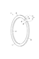
- FIG. 1 is a perspective view of a piston ring according to an embodiment.
- FIG. 2 is a plan view showing a state where the piston ring according to the embodiment is mounted on a cylinder.
- 3 is a cross-sectional view taken along line III-III in FIG.
- FIG. 4 is a development view of the outer peripheral surface.
- FIG. 5 is a graph showing the relationship between the width of the contact surface of the piston ring and the amount of friction loss.
- FIG. 6 is a cross-sectional view of a main body portion of a piston ring according to a modification of the embodiment.
- FIG. 7 is a diagram for explaining the friction loss test.
- FIG. 1 is a perspective view of a piston ring according to the present embodiment.
- FIG. 2 is a plan view showing the piston ring according to the present embodiment mounted on a cylinder.
- a piston ring 1 shown in FIGS. 1 and 2 is used as a second ring provided in a ring groove on an outer peripheral surface of a piston, for example, in an internal combustion engine of an automobile.
- the piston ring 1 slides against the cylinder inner wall, so that oil on the cylinder inner wall enters the combustion chamber side from the crank chamber side (oil-up), and blow-by gas enters the crank chamber side from the combustion chamber side. The function which suppresses this is played.
- the piston ring 1 has an annular main body portion 2 and a joint portion 3 formed in a part of the main body portion 2.
- the main body 2 has a side surface (one side surface) 2a and a side surface (other side surface) 2b, and an inner peripheral surface 2c and an outer peripheral surface 2d.
- the direction connecting the side surface 2a and the side surface 2b is the width direction of the piston ring 1
- the direction connecting the inner peripheral surface 2c and the outer peripheral surface 2d is the thickness direction of the piston ring 1.
- the main body 2 has a substantially rectangular cross section in which the thickness direction is a long side and the width direction is a short side.
- the width of the main body 2 is, for example, 0.5 mm to 4.0 mm, and the thickness of the main body 2 is, for example, 1.7 mm to 5.0 mm.
- the outer diameter (nominal diameter) of the main-body part 2 is 50 mm or more and 150 mm or less, for example.
- Each dimension of the main-body part 2 can be measured using a contact-type or non-contact-type shape measuring device (including a surface roughness measuring device).
- the main body 2 is made of, for example, cast iron or steel (steel) containing a plurality of metal elements and has sufficient strength, heat resistance, and elasticity.
- the surface of the main body 2 may be surface-modified by, for example, a hard chromium plating layer, a chromium nitride layer, or an iron nitride layer.
- the biaxial difference of the main body 2 is greater than ⁇ 0.25 mm and less than +0.36 mm.
- the biaxial difference is the difference between the main body 2 in the direction along the first axis Y (first axial direction) passing through the center X of the piston ring 1 and the center position of the joint 3 in a plan view.
- the diameter d2 is a value corresponding to the nominal diameter of the piston ring 1.
- the biaxial difference (d2 ⁇ d1) of the main body 2 may be ⁇ 0.23 mm or more, and may be +0.31 mm or less.
- the abutment portion 3 is a portion where a part of the main body portion 2 is divided, and is formed by a pair of abutment end portions 4 and 5 facing each other.
- the pair of joint end portions 4 and 5 are portions that are free ends of the main body portion 2.
- the gap (abutment gap) of the abutment portion 3 is narrowed, for example, when the piston ring 1 is heated and thermally expanded. That is, the abutment portion 3 functions as a relief portion for the thermal expansion of the main body portion 2 due to a temperature difference between the piston ring 1 and the cylinder when the piston ring 1 is used.
- 3 is a cross-sectional view taken along line III-III in FIG.
- the outer peripheral surface 2 d is provided with an inclined surface 11, a contact surface 12, a connection surface 13, and a notch 21.
- the inclined surface 11 is inclined so as to project in the radial direction of the main body 2 as it goes from the side surface 2a to the side surface 2b.
- the inclined surface 11 extends over the entire circumferential direction of the main body 2.
- the inclination angle ⁇ of the inclined surface 11 is, for example, 3 ° 30 ′ or less (3 degrees 30 minutes or less).
- the width of the inclined surface 11 is, for example, 50% or more of the width of the main body 2.
- connection surface 13 is a portion where a corner formed by the side surface 2a and the outer peripheral surface 2d is chamfered, and is a surface that connects the inclined surface 11 and the side surface 2a.
- the connecting surface 13 extends along the entire inclined surface 11 in the circumferential direction of the main body 2.
- the connection surface 13 is inclined so as to project in the radial direction of the main body 2 as it goes from the side surface 2 a to the side surface 2 b at an inclination angle larger than that of the inclined surface 11.
- the connection surface 13 may have an R shape.
- the contact surface 12 is a surface that protrudes most in the radial direction in the outer peripheral surface 2d.
- the contact surface 12 slides in contact with the inner wall of the cylinder when the piston ring 1 is mounted in the ring groove of the piston.
- the contact surface 12 extends over the entire circumferential direction of the main body 2.
- the contact surface 12 is substantially orthogonal to the side surfaces 2a and 2b and is substantially parallel to the inner peripheral surface 2c.
- the notch portion 21 is a portion where a corner portion formed by the side surface 2b and the outer peripheral surface 2d is notched, and extends over the entire circumferential direction of the main body portion 2.
- the cutout portion 21 is formed by cutting out a part of the main body portion 2 on the side surface 2b side and the outer peripheral surface 2d side, for example, with a jig for cutting, grinding, or polishing.
- the notch part 21 may be formed by carrying out plastic working of the said part of the main-body part 2 by rolling or drawing.
- the notch 21 has a first surface 21a facing the outer peripheral surface 2d side and a second surface 21b facing the side surface 2b.
- the first surface 21a extends substantially parallel to the inner peripheral surface 2c
- the second surface 21b extends substantially parallel to the side surfaces 2a and 2b.
- corner which the 1st surface 21a and the 2nd surface 21b make is a substantially right angle.
- the corner portion 22 formed by the second surface 21b and the contact surface 12 of the outer peripheral surface 2d is provided by chamfering.
- the corner 22 may have an R shape. In this case, the radius of curvature R of the corner portion 22 may be about 0.1 mm, for example.
- FIG. 4 is a development view of the outer peripheral surface.
- corners formed by the connection surface and the cutout portion of the outer peripheral surface, and the second surface and the contact surface are omitted.
- the contact surface 12 is formed over the entire outer peripheral surface 2d from one abutment end 4 to the other abutment end 5.
- a contact surface 12 is formed by peripherally lapping the end portion 14 (the portion indicated by the phantom line in FIG. 3) on the side surface 2b of the inclined surface 11 in FIG.
- Peripheral lapping is performed by attaching a piston ring to a cylinder having the same diameter as the cylinder that is actually installed, and lapping within a sleeve having an inner diameter equal to the outer diameter (nominal diameter) of the piston ring.
- This is a processing method for forming a contact surface along the outer peripheral surface.
- the peripheral lapping is performed in the final process of manufacturing the piston ring.
- the self-tension per nominal diameter of the piston ring 1 at the time of outer peripheral lapping is set to 0.20 N / mm or less, for example.
- the contact surface 12 When the contact surface 12 is formed by the outer circumferential lapping, the abutment end portions 4 and 5 that are free ends project to the sleeve side, so that the processing amount of the abutment end portions 4 and 5 is the abutment end portions 4 and 5. There is a tendency that the amount of processing is larger than the processing amount of the portion excluding (hereinafter referred to as “main portion 6”). This tendency appears more strongly as it is closer to the end faces 4a and 5a. Therefore, as shown in FIG. 4, the contact surface 12 has a region 12 a in which the width gradually increases toward the end surface 4 a of the joint end 4, and a width gradually increases toward the end surface 5 a of the joint end 5. Increasing regions 12b are formed respectively.
- the maximum width W1 is 80% of the maximum width W2. More than 150%.
- the contact surface 12 at the abutting end portions 4 and 5 has a substantially symmetric shape across the abutting portion 3.
- the upper side of the contact surface 12 is inclined with respect to the lower side substantially parallel to the side surfaces 2 a and 2 b in the contact surface 12. For this reason, the width
- the inclination angle of the upper side with respect to the lower side is, for example, 0.05 mm / deg or less (0.05 mm or less per angle). This inclination angle can be obtained, for example, by linearly approximating the upper side of the contact surface 12 at the joint end portions 4 and 5.
- the maximum width W2 of the contact surface 12 in the main portion 6 is 1% or more and 50% or less of the width of the main body portion 2.
- the maximum width W2 is preferably 30% or less of the width of the main body portion 2, and more preferably 20% or less of the width of the main body portion 2. Therefore, in this embodiment, the maximum width W2 is set to 0.005 mm or more and 0.5 mm or less, for example. Further, the maximum width W1 is set to 0.004 mm or more and 0.75 mm or less.
- the maximum widths W1 and W2 are initial values of the maximum width of the contact surface 12 formed by the outer peripheral lapping, and indicate the width before the change due to wear occurs. Further, when the center position of the abutment portion 3 is set to 0 ° (or 360 °) in a state where the piston ring 1 is attached to a cylinder having the same diameter as the cylinder that is actually attached, the end portion of the abutment is shown. 4, the contact surface 12 (region 12a) indicates a portion located in a range of 0 ° to 15 °, and the contact surface 12 (region 12b) in the abutting end portion 5 is a portion positioned in a range of 345 ° to 360 °. Point to.
- the contact surface 12 in the main portion 6 refers to a portion located in a range greater than 15 ° and less than 345 °.
- the center position of the abutment portion 3 is an intermediate position between the abutment end portions 4 and 5 when the side surface 2b of the main body portion 2 is placed on a flat surface.
- the interval between the abutment end portions 4 and 5 is the same as the interval between the abutment end portions 4 and 5 when the piston ring 1 is accommodated in a casing (ring gauge) having a size equal to the nominal diameter at room temperature. It is equivalent.
- a portion of the main body 2 located on the opposite side of the joint ends 4 and 5 (for example, a portion located in the range of 150 ° to 210 ° in the main portion 6) is the joint end when the piston ring 1 is mounted on the cylinder.
- the width of the contact surface 12 in the portion located on the opposite side of the joint end portions 4 and 5 tends to be the smallest in the entire contact surface 12.
- the maximum width W1 of the abutting end portions 4 and 5 is located on the opposite side of the abutting end portions 4 and 5 with reference to the maximum width of the abutting surface 12 of the portion where the width of the abutting surface 12 tends to be the smallest. It is preferably 80% or more and 150% or less of the maximum width of the contact surface 12 in the portion.
- the maximum width W1 of the contact surface 12 of the joint end portions 4 and 5 is 150% or less of the maximum width W2 of the contact surface 12 in the main portion 6.
- the biaxial difference (d2-d1) is less than +0.36 mm.
- the processing accuracy of the contact surface 12 can be sufficiently secured, and the contact surface 12 satisfying the above range is obtained.
- the biaxial difference (d2-d1) is larger than -0.25 mm. Therefore, even when the back pressure is small, the sealing performance by the outer peripheral surface 2d can be sufficiently exhibited.
- the contact surface 12 at the abutment end portion 4 is a portion located in the range of 0 ° to 15 °
- the abutment end portion 5 The contact surface 12 is a portion located in a range of 345 ° to 360 °
- the contact surface 12 in the main portion 6 is a portion located in a range larger than 15 ° and smaller than 345 °.
- the maximum width W1 is preferably 80% to 150% of the maximum width of the contact surface 12 in the range of 150 ° to 210 ° in the main portion 6.
- the maximum width W1 satisfies the above range with respect to the maximum width of the range in which the width tends to be the smallest on the contact surface 12 of the main portion 6, so that the width of the contact surface 12 by the part of the main body portion 2 is increased.
- the variation is more preferably suppressed.
- the piston ring 1 can suitably form an oil film on the inner wall of the cylinder. Suppressing oil to the combustion chamber can be suppressed. Further, an increase in friction loss due to the contact surface 12 can be avoided.
- FIG. 5 is a graph showing an example of the relationship between the width of the contact surface of the piston ring and the friction loss.
- the vertical axis indicates the initial friction loss
- the horizontal axis indicates the width of the contact surface.
- the maximum width W2 of the contact surface 12 of the main portion 6 is set to 0.005 mm or more and 0.5 mm or less (that is, the maximum width W2 is set to 1% or more and 50% or less of the width of the main body portion 2).
- the initial friction loss due to the piston ring 1 can be suitably suppressed.
- a notch 21 extends in the circumferential direction of the main body 2 at the corner formed by the side surface 2 b and the outer peripheral surface 2 d. In this case, the oil scraped off by the piston ring 1 can be made to flow through the notch 21.
- the sealing performance by the outer peripheral surface 2d can be sufficiently exhibited even when the back pressure is small.
- a second ring in which a protective film or the like is not formed on the outer peripheral surface 2d is illustrated, but as shown in FIG. 6, the main body portion 2 is the outermost surface of the outer peripheral surface 2d in the main body portion 2.
- the hard film 31 having higher hardness may extend over the entire circumferential direction of the main body 2.
- the hard film 31 is formed as the outermost surface of the outer peripheral surface 2d.
- the inclined surface 11, the connection surface 13, and the notch 21 are formed.
- the contact surface 12 is formed by carrying out the outer periphery lapping of the edge part by the side of the side surface 2b in the inclined surface 11 formed of the hard film 31.
- FIG. The corner formed in the piston ring 1 by chamfering or the like may be rounded.
- the hard film 31 is a physical vapor deposition film (PVD film) formed using a physical vapor deposition method (PVD method). Thereby, the hard film 31 can be formed with sufficient hardness.
- the hardness of the hard film 31 is, for example, 800 HV0.05 or more and 2000 HV0.05 or less in terms of Vickers hardness, and is about twice or more higher than the hardness of the main body 2.
- the hard film 31 is an ion plating film or a diamond-like carbon film containing at least one of titanium (Ti) and chromium (Cr) and at least one of carbon (C), nitrogen (N), and oxygen.
- the hard film 31 is a titanium nitride film, a chromium nitride film, a titanium carbonitride film, a chromium carbonitride film, a chromium oxynitride film, a chromium film, or a titanium film.
- a chromium nitride film when importance is attached to wear resistance and scuff resistance, it is preferable to use a chromium nitride film.
- the hard film 31 may be a laminated body, and may include, for example, a chromium nitride film and a diamond-like carbon film.
- the contact surface 12 which is 80% to 150% of W2 can be formed with a higher yield.
- the thickness of the hard film 31 along the radial direction of the main body 2 is 1 ⁇ m or more and 30 ⁇ m or less. Thereby, the thickness of the hard film 31 becomes sufficient, and the progress of wear on the contact surface 12 can be suppressed.
- an undercoat such as a chromium film or a titanium film may be applied to the main body 2.
- the cutout portion 21 is cut out in a step shape in cross section, but the cutout portion 21 may be cut out in a hook shape in cross section.
- the contact surface is provided on the side surface 2b side from the center in the width direction of the main body 2, but may be provided on the side surface 2a side from the center.
- the piston ring according to the above embodiment and the above modification can be used as, for example, a top ring or a third ring in a diesel engine in addition to the second ring.
- the end surface 4a of the abutment edge part 4 and the end surface 5a of the abutment edge part 5 have illustrated the right angle abutment formed at right angles with respect to the circumferential direction of the main-body part 2,
- the shape of the end is not limited to this.
- the end surfaces 4a and 5a may be inclined joints formed to be inclined with respect to the circumferential direction, and are formed so that the side surface 2a side of the end surface 4a and the side surface 2b side of the end surface 5a protrude toward each other. It may be a stepped joint.
- Example 1 The present invention will be described in more detail with reference to the following examples, but the present invention is not limited to these examples.
- Example 1
- the second ring of Example 1 was produced by the following procedure. First, a ring having a main body portion having an inclined surface on the outer peripheral surface was produced. As the ring body, JIS standard silicon chrome steel oil temper wire (SWOSC-V) was used as the wire, and the wire was subjected to rolling roll forming and pultrusion forming. The nominal diameter of the main body was set to 80 mm. Moreover, the width
- SWOSC-V JIS standard silicon chrome steel oil temper wire
- Example 1 side surface processing and joint processing were performed on the main body, and then outer peripheral lapping was performed using a perfect circle sleeve having an inner diameter of 80 mm.
- the processing conditions were adjusted by outer peripheral lapping so that the hit width was 0.1 mm (about 8% of the width of the main body 2) over the entire circumference of the main body.
- the zinc phosphate process was performed as a surface treatment with respect to the whole surface of a main-body part.
- the biaxial difference (d2-d1) between the diameter d1 of the main body portion along the first axial direction and the diameter d2 of the main body portion along the second axial direction is shown in Table 1 below. It adjusted to the value shown in.
- the maximum width W1 of the joint end and the maximum width W2 of the main part were adjusted to the values shown in Table 1 below.
- the ratio (W1 / W2) of the maximum width W1 of the joint end portion to the maximum width W2 of the main portion is also shown. (Examples 2, 4-7, 10, 12-14, 16)
- a second ring was produced in the same manner as in Example 1 except for the items described below.
- the specifications of each second ring in these examples are as shown in Table 1 below.
- a chromium nitride film (CrN film) was formed on the outer peripheral surface of the main body as a hard film by the PVD method after the above-described joint processing.
- the thickness of the chromium nitride film was set to 15 ⁇ m.
- outer periphery lapping was performed in the same manner as in Example 1 and the like. Thereby, the contact surface was formed in the chromium nitride film
- the second ring of the comparative example was produced in the same procedure as in Example 1.
- the specifications of each second ring are as shown in Table 1 below. (Comparative Examples 4, 7, 9, 11, 12)
- the second ring of the above comparative example having a hard film was prepared in the same procedure as in Example 3.
- the specifications of each second ring are as shown in Table 1 below. (Verification of oil consumption)
- the second ring of each example and each comparative example was installed in a piston second ring groove in a gasoline engine with a displacement of 2.4 L and an inline 4-cylinder. Then, the measurement of oil consumption (LOC: Low Oil Consumption) when the gasoline engine was operated for a predetermined time under the conditions of 6800 rpm (6800 min ⁇ 1 ) and full load (WOT: Wide Open Throttle) It carried out with respect to each comparative example.
- LOC Low Oil Consumption
- WOT Wide Open Throttle
- a piston ring set 41 including a top ring 42 and an oil ring 43 and a second ring 44 of each example and each comparative example was prepared.
- the piston ring set 41 was mounted on a piston 45 of a floating liner type friction measurement engine, and the friction loss of each second ring 44 was evaluated by friction average effective pressure (FMEP: Friction Mean Effective Pressure).
- FMEP Friction Mean Effective Pressure
- a cast iron cylinder liner 46 was used as a counterpart material that slides with the top ring 42, the second ring 44, and the oil ring 43.
- the ten-point average roughness (Rz) of the cylinder liner 46 was 2 to 4 ⁇ m.
- a load measuring sensor 47 is attached to the outer periphery of the cylinder liner 46.
- the tension of the top ring 42 was set to 3N
- the tension of the second ring 44 was set to 2N
- the tension of the oil ring 43 was set to 15N.
- Example 4 where the biaxial difference is near the upper limit (+0.31 mm) of the present invention, both LOC and FMEP were reduced as compared with Comparative Example 1.
- Comparative Example 14 in which the biaxial difference exceeds the upper limit (+0.36 mm) of the present invention, LOC was reduced as compared with Comparative Example 1, but FMEP increased as compared with Comparative Example 1. It became. From this result, it was demonstrated that both LOC and FMEP can be reduced by setting the biaxial difference to less than +0.36 mm and W1 / W2 to 80% or more and 150% or less.
- Example 19 where the biaxial difference is near the lower limit ( ⁇ 0.23 mm) of the present invention, both LOC and FMEP were reduced compared to Comparative Example 1.
- Comparative Example 4 in which the biaxial difference exceeds the lower limit ( ⁇ 0.25 mm) of the present invention, FMEP was reduced as compared with Comparative Example 1, but LOC increased as compared with Comparative Example 1.
- Comparative Example 13 in which the biaxial difference exceeds the lower limit ( ⁇ 0.25 mm) of the present invention, and W1 / W2 is outside the range of 80% to 150% (76.7%).
- FMEP was lower than that of Comparative Example 1, but LOC was increased as compared with Comparative Example 1. From these results, it was proved that both LOC and FMEP can be reduced by making the biaxial difference larger than ⁇ 0.25 mm and setting W1 / W2 to 80% or more and 150% or less.
Landscapes
- Engineering & Computer Science (AREA)
- General Engineering & Computer Science (AREA)
- Mechanical Engineering (AREA)
- Chemical & Material Sciences (AREA)
- Combustion & Propulsion (AREA)
- Pistons, Piston Rings, And Cylinders (AREA)
Abstract
外周面によるシール性を十分に発揮させることができ、面圧の低下によるオイル消費量の増加及び摩耗の進行による摩擦損失の増加を低減できるピストンリングを提供する。ピストンリング1は、内周面2c及び外周面2dと、内周面2cに略直交する側面2a,2bと、互いに対向して合口部3を形成する一対の合口端部4,5とを有する環状の本体部2を備え、外周面2dは、傾斜面11と、傾斜面11の側面2b側に設けられ、内周面2cと略平行に延在する当たり面12とを有している。合口端部4,5における当たり面12の最大幅W1は、主部6における当たり面12の最大幅W2の80%以上150%以下となっている。本体部2において、合口部3の中心位置を通る第1軸方向の直径d1と、第1軸方向に直交する第2軸方向の直径d2との間の二軸差(d2-d1)は、-0.25mmより大きく、+0.36mm未満となっている。
Description
本発明は、内燃機関等に使用されるピストンリングに関する。
自動車等の内燃機関に用いられるピストンリングは、例えばピストン外周面のリング溝に設けられ、シリンダ内壁のオイルがクランク室側から燃焼室側に入り込むこと(オイルアップ)と、ブローバイガスが燃焼室側からクランク室側に入り込むこととを抑制するシール機能を有している。このようなシール機能を有するピストンリングとして、例えば特許文献1に記載のピストンリングがある。この従来のピストンリングは、内燃機関のセカンドリングとして用いられ、外周面の上側面側に設けられて径方向に張り出すように傾斜する傾斜面と、傾斜面の下端から設けられてシリンダ内壁と摺接する当たり面とを有している。
また、特許文献2に記載のピストンリングでは、本体部において合口部の反対側に位置する部分の厚さが他の部分よりも厚くなっている。このピストンリングでは、本体部の面内方向に力が作用しない状態(自由状態)において楕円に近い形状となっている。特許出願2では、本体部を台に載置させて合口隙間を使用時の寸法まで閉じた状態において、合口部の中心位置を通る第1軸方向の直径d1と、第1軸方向に直交する第2軸方向の直径d2との間の二軸差(d2-d1)がマイナスとなっている。
ピストンリングの当たり面の形成には、例えばリングの自己張力を利用した外周ラップ加工が採用される。この外周ラップ加工は、ピストンリングの製造の最終工程において実施されるものであり、実際に装着されるシリンダと同径のシリンダにピストンリングを装着し、当該ピストンリングの外径(呼称径)に等しい内径を有するスリーブ内でラッピングを行うことにより、ピストンリングの外周面に沿った当たり面を形成する加工方法である。しかしながら、外周ラップ加工によって当たり面を形成する際、自由端となっている合口端部がスリーブ側に張り出すことで、当該合口端部の加工量が他の部位の加工量よりも増大する傾向がある。この傾向は、ピストンリングの二軸差がプラス側に大きくなる程強くあらわれる。当たり面の加工精度は、シリンダ内壁に対する面圧の低下によるオイル消費量の増加や、摩耗の進行による摩擦損失の増加といった問題に直結するため、その向上が課題となっている。
外周ラップ加工の加工精度を担保するため、上記特許文献2に示されるように、ピストンリングの二軸差をマイナスに設定することが考えられる。しかしながら、ピストンリングの二軸差をマイナスにした場合には、合口端部の摩耗の進行の問題は抑えられる一方で、ピストンリングのシール機能が十分に発揮されなくなるおそれが生じる。トップリングでは、燃焼時のガス圧力がピストンリングの上側面からリング溝に回り込み、内周面側からの背圧となる。この背圧によってピストンリングの外周面がシリンダ内壁に押し付けられることによって、ピストンリングのシール性が確保される。これに対し、セカンドリングでは、背圧がトップリングに比べて小さいため、ピストンリングの外周面によるシール性は、ピストンリングの面圧分布によって左右されることとなる。
本発明の一側面は、外周面によるシール性を十分に発揮させることができ、面圧の低下によるオイル消費量の増加及び摩耗の進行による摩擦損失の増加を低減できるピストンリングを提供することを目的とする。
本発明の一側面に係るピストンリングは、内周面及び外周面と、内周面に略直交する一側面及び他側面と、互いに対向して合口部を形成する一対の合口端部とを有する環状の本体部を備えたピストンリングであって、外周面は、一側面側から他側面側に向かうにつれて本体部の径方向に張り出すように傾斜する傾斜面と、傾斜面の他側面側に設けられ、内周面と略平行に延在する当たり面と、を有し、一側面と他側面とを結ぶ方向において、合口端部における当たり面の最大幅W1は、合口端部以外の部分における当たり面の最大幅W2の80%以上150%以下であり、本体部において、合口部の中心位置を通る第1軸方向の直径d1と、第1軸方向に直交する第2軸方向の直径d2との間の二軸差(d2-d1)は、-0.25mmより大きく、+0.36mm未満である。
このピストンリングでは、合口端部の当たり面の最大幅W1が、合口端部以外の部分における当たり面の最大幅W2の150%以下となっている。この範囲を満たすことで、本体部の部位による当たり面の幅のばらつきが抑えられるので、面圧の低下によるオイル消費量の増加及び摩耗の進行による摩擦損失の増加を抑制できる。また、このピストンリングでは、二軸差(d2-d1)が+0.36mm未満となっている。このため、外周ラップ加工の際に合口端部が自己張力によってスリーブ側に張り出すことが抑制され、当たり面の加工精度を十分に確保でき、上記範囲を満たす当たり面を歩留まり良く形成できる。さらに、このピストンリングでは、二軸差(d2-d1)が-0.25mmより大きくなっている。したがって、背圧が小さい場合でも外周面によるシール性を十分に発揮させることが可能となる。
外周面の最表面として、本体部よりも高い硬度を有する硬質膜が本体部の周方向に延在していてもよい。硬質膜を用いることにより、当たり面の摩耗の進行を抑えることができる。また、外周ラップ加工の際の、合口端部における当たり面の最大幅W1と、合口端部以外の部分における当たり面の最大幅W2との差を小さくすることが可能となり、上記範囲を満たす当たり面を一層歩留まり良く形成できる。
硬質膜は、物理気相成長膜であってもよい。この場合、硬質膜を十分な硬度で形成できる。
硬質膜は、窒化チタン膜、窒化クロム膜、炭窒化チタン膜、炭窒化クロム膜、酸窒化クロム膜、クロム膜、チタン膜、及びダイヤモンドライクカーボン膜からなる群より選ばれる少なくとも一つの膜を含んでもよい。この場合、硬質膜を十分な硬度で形成できる。
硬質膜の厚さは、1μm以上30μm以下であってもよい。この場合、硬質膜の厚さが十分なものとなり、当たり面における摩耗の進行を抑制できる。
合口部の中心位置を0°として本体部の位置を角度で表したとき、一方の合口端部における当たり面は、0°~15°の範囲に位置する部分であり、他方の合口端部における当たり面は、345°~360°の範囲に位置する部分であり、合口端部以外の部分における当たり面は、15°より大きく345°よりも小さい範囲に位置する部分であってもよい。合口端部を上記範囲として当たり面の最大幅の関係を満たすことで、面圧の低下によるオイル消費量の増加及び摩耗の進行による摩擦損失の増加を効果的に抑制できる。
最大幅W1は、合口端部以外の部分における150°~210°の範囲の当たり面の最大幅の80%以上150%以下であってもよい。このように最大幅W1が、合口端部以外の部分の当たり面において最も幅が小さくなる傾向にある範囲の最大幅に対して上記範囲を満たすことにより、本体部の部位による当たり面の幅のばらつきがより好適に抑えられる。
最大幅W2は、本体部の幅の1%以上50%以下であってもよい。この範囲を満たすことで、シリンダ内壁にオイル膜を好適に形成できると共に、当たり面によるオイルの燃焼室への掻き上げを抑制できる。また、当たり面による摩擦損失の増大を回避できる。
最大幅W2は、0.005mm以上0.5mm以下であってもよい。この範囲を満たすことで、ピストンリングによる初期の摩擦損失を抑制できる。
本体部において、他側面と外周面とがなす角部には、切欠部が本体部の周方向に延在していてもよい。この場合、ピストンリングによって掻き取られたオイルを切欠部に流すことが可能となる。
ピストンリングは、セカンドリングであってもよい。上記ピストンリングをセカンドリングとして用いることにより、背圧が小さい場合でも外周面によるシール性を十分に発揮させることが可能となる。
本発明の一側面によれば、外周面によるシール性を十分に発揮させることができ、面圧の低下によるオイル消費量の増加及び摩耗の進行による摩擦損失の増加を低減できる。
以下、添付図面を参照して、本発明の一側面の好適な実施形態について詳細に説明する。なお、以下の説明において、同一要素又は同一機能を有する要素には、同一符号を用いることとし、重複する説明は省略する。
図1は、本実施形態に係るピストンリングの斜視図である。また、図2は、本実施形態に係るピストンリングをシリンダに装着した状態で示す平面図である。図1及び図2に示されるピストンリング1は、例えば自動車の内燃機関においてピストン外周面のリング溝に設けられるセカンドリングとして用いられる。このピストンリング1は、シリンダ内壁に対して摺動することで、シリンダ内壁のオイルがクランク室側から燃焼室側に入り込むこと(オイルアップ)と、ブローバイガスが燃焼室側からクランク室側へ入り込むこととを抑制する機能を奏するようになっている。
ピストンリング1は、環状の本体部2と、本体部2の一部に形成された合口部3とを有している。本体部2は、側面(一側面)2a及び側面(他側面)2bと、内周面2c及び外周面2dとを有している。以下の説明では、側面2aと側面2bとを結ぶ方向をピストンリング1の幅方向とし、内周面2cと外周面2dとを結ぶ方向をピストンリング1の厚さ方向とする。
本体部2は、厚さ方向が長辺かつ幅方向が短辺となる断面略長方形状をなしている。本体部2の幅は、例えば0.5mm以上4.0mm以下となっており、本体部2の厚さは、例えば1.7mm以上5.0mm以下となっている。また、本体部2の外径(呼称径)は、例えば50mm以上150mm以下となっている。本体部2の各寸法は、接触式又は非接触式の形状測定装置(表面粗さ測定装置を含む)を用いて測定できる。かかる本体部2は、例えば複数の金属元素を含有する鋳鉄或いは鋼(スチール)を用い、十分な強度、耐熱性、及び弾性をもって形成されている。本体部2の表面には、例えば硬質クロムめっき層、クロム窒化物層、或いは鉄窒化物層などによって表面改質が施されていてもよい。このような表面改質層を少なくとも側面2bに形成することにより、ピストンのリング溝に対する本体部2の耐摩耗性の向上が図られる。
本体部2の二軸差は、-0.25mmより大きく、+0.36mm未満となっている。二軸差は、図2に示すように、平面視におけるピストンリング1の中心Xと合口部3の中心位置とを通る第1軸Yに沿った方向(第1軸方向)の本体部2の直径d1と、平面視におけるピストンリング1の中心Xを通って第1軸方向に直交する第2軸Zに沿った方向(第2軸方向)の本体部2の直径d2との差(d2-d1)で表される。本実施形態では、直径d2は、ピストンリング1の呼称径に相当する値である。本体部2の二軸差(d2-d1)は、-0.23mm以上であってもよく、+0.31mm以下であってもよい。
合口部3は、本体部2の一部が分断された部分であり、互いに対向する一対の合口端部4,5によって形成されている。一対の合口端部4,5は、それぞれ本体部2の自由端となっている部分である。合口部3の隙間(合口隙間)は、例えばピストンリング1が加熱されて熱膨張したときに狭まるようになっている。すなわち、合口部3は、ピストンリング1の使用時において、ピストンリング1とシリンダとの間の温度差に起因する本体部2の熱膨張分の逃げ部として機能する。
次に、本体部2の外周面2dについて更に詳細に説明する。図3は、図2におけるIII-III線断面図である。
図3に示されるように、外周面2dには、傾斜面11と、当たり面12と、接続面13と、切欠部21とが設けられている。傾斜面11は、側面2aから側面2bに向かうにつれて本体部2の径方向に張り出すように傾斜している。傾斜面11は、本体部2の周方向の全体にわたって延在している。傾斜面11の傾斜角θは、例えば3°30′以下(3度30分以下)となっている。傾斜面11の幅は、例えば本体部2の幅の50%以上となっている。傾斜面11の形成により、本体部2は、いわゆるテーパフェイス形状となっている。これにより、ピストンリング1をピストンのリング溝に装着した際に、外周面2dの側面2b側のみがシリンダ内壁に対して摺動する。したがって、シリンダ内壁に対してピストンリング1が接する面積が低減するので、シリンダ内壁との摩擦を低減させつつ、オイルの掻き取りを良好に実施できる。
接続面13は、側面2aと外周面2dとがなす角部が面取りされた部分であり、傾斜面11と側面2aとを接続する面である。接続面13は、傾斜面11と共に本体部2の周方向の全体にわたって延在している。接続面13は、傾斜面11よりも大きい傾斜角度で側面2aから側面2bに向かうにつれて本体部2の径方向に張り出すように傾斜している。なお、接続面13は、R形状をなしていてもよい。当たり面12は、外周面2dのうち径方向に最も張り出している面である。当たり面12は、ピストンリング1をピストンのリング溝に装着した際に、シリンダ内壁に接して摺動する。当たり面12は、本体部2の周方向の全体にわたって延在している。また、当たり面12は、側面2a,2bと略直交し、かつ内周面2cと略平行になっている。
切欠部21は、側面2bと外周面2dとがなす角部が切り欠かれた部分であり、本体部2の周方向の全体にわたって延在している。切欠部21は、例えば切削用、研削用、又は研磨用の治具等によって、側面2b側且つ外周面2d側の本体部2の一部を全周にわたって切り欠くことで形成される。また、切欠部21は、本体部2の上記一部を圧延もしくは絞り加工等で塑性加工することによって形成されてもよい。
切欠部21は、外周面2d側を向く第1面21aと、側面2bを向く第2面21bとを有している。第1面21aは、内周面2cと略平行に延在し、第2面21bは側面2a,2bと略平行に延在している。このため、第1面21aと第2面21bとがなす角は、略直角になっている。なお、第2面21bと外周面2dの当たり面12とがなす角部22は、面取りによって設けられる。角部22は、R形状を有してもよい。この場合、角部22の曲率半径Rは、例えば0.1mm程度とすればよい。
次に、上述した当たり面12について更に詳細に説明する。図4は、外周面の展開図である。図4において、外周面のうち接続面及び切欠部と、上記第2面と当たり面とがなす角部は省略されている。
同図に示すように、当たり面12は、一方の合口端部4から他方の合口端部5に至るまで外周面2dの全体にわたって形成されている。このような当たり面12は、図3において傾斜面11における側面2b側の端部14(図3において仮想線で示す部分)を外周ラップ加工することによって形成される。外周ラップ加工は、実際に装着されるシリンダと同径のシリンダにピストンリングを装着し、当該ピストンリングの外径(呼称径)に等しい内径を有するスリーブ内でラッピングを行うことにより、ピストンリングの外周面に沿って当たり面を形成する加工方法である。外周ラップ加工は、ピストンリングの製造の最終工程において実施される。外周ラップ加工時のピストンリング1の呼称径当たりの自己張力は、例えば0.20N/mm以下に設定される。
この外周ラップ加工によって当たり面12を形成する際、自由端となっている合口端部4,5がスリーブ側に張り出すことで、合口端部4,5の加工量が合口端部4,5を除く部分(以下、当該部分を「主部6」と称す)の加工量よりも増大する傾向がある。この傾向は、端面4a,5aに近いほど強くあらわれる。このため、図4に示すように、当たり面12には、合口端部4の端面4aに向かうにつれて幅が徐々に増加する領域12aと、合口端部5の端面5aに向かうにつれて幅が徐々に増加する領域12bとがそれぞれ形成されている。
図4の例では、合口端部4,5における当たり面12の最大幅をW1とし、主部6における当たり面12の最大幅をW2とした場合、最大幅W1は、最大幅W2の80%以上150%以下となっている。合口端部4,5における当たり面12は、合口部3を挟んでほぼ対称の形状となっている。合口端部4,5のそれぞれでは、当たり面12の上辺は、当たり面12において側面2a,2bに略平行な下辺に対して傾斜している。このため、端面4a,5aにおける当たり面12の幅が最大幅W1となっている。また、合口端部4,5の当たり面12において、上記上辺の上記下辺に対する傾斜角は、例えば0.05mm/deg以下(0.05ミリメートル毎角度以下)となっている。この傾斜角は、例えば合口端部4,5における当たり面12の上辺を直線近似することによって求めることができる。
主部6における当たり面12の最大幅W2は、本体部2の幅の1%以上50%以下となっている。最大幅W2は、本体部2の幅の30%以下であることが好ましく、本体部2の幅の20%以下であることがより好ましい。したがって、本実施形態では、最大幅W2は、例えば0.005mm以上0.5mm以下に設定されている。また、最大幅W1は、0.004mm以上0.75mm以下に設定されている。
なお、ここでの最大幅W1,W2とは、外周ラップ加工によって形成された当たり面12の最大幅の初期値であり、摩耗による変化が生じる前の幅を指している。また、ピストンリング1を実際に装着されるシリンダと同径のシリンダに装着した状態において、合口部3の中心位置を0°(若しくは360°)とした場合(図2参照)に、合口端部4における当たり面12(領域12a)は、0°~15°の範囲に位置する部分を指し、合口端部5における当たり面12(領域12b)は、345°~360°の範囲に位置する部分を指す。主部6における当たり面12は、15°よりも大きく345°未満の範囲に位置する部分を指す。合口部3の中心位置は、本体部2の側面2bを平坦面に載置したときの合口端部4,5間の中間位置である。このときの合口端部4,5間の間隔は、室温にてピストンリング1をその呼称径に等しい寸法の筐体(リングゲージ)内に収容したときの合口端部4,5間の間隔と同等である。
本体部2において合口端部4,5の反対側に位置する部分(例えば、主部6における150°~210°の範囲に位置する部分)は、ピストンリング1をシリンダに装着した際に合口端部4,5と比較してスリーブに張り出しにくく、外周ラップ加工が施されにくい部分である。このため、合口端部4,5の反対側に位置する部分における当たり面12の幅は、当たり面12全体の中で最も小さくなる傾向にある。したがって、当たり面12の幅が最も小さくなる傾向にある部分の当たり面12の最大幅を基準とし、合口端部4,5の最大幅W1は、合口端部4,5の反対側に位置する部分における当たり面12の最大幅の80%以上150%以下であることが好ましい。
以上に説明した構成を有するピストンリング1では、合口端部4,5の当たり面12の最大幅W1が、主部6における当たり面12の最大幅W2の150%以下となっている。この範囲を満たすことで、本体部2の部位による当たり面12の幅のばらつきが抑えられるので、面圧の低下によるオイル消費量の増加及び摩耗の進行による摩擦損失の増加を抑制できる。また、このピストンリング1では、二軸差(d2-d1)が+0.36mm未満となっている。このため、外周ラップ加工の際に合口端部4,5が自己張力によってスリーブ側に張り出すことが抑制され、当たり面12の加工精度を十分に確保でき、上記範囲を満たす当たり面12を歩留まり良く形成できる。さらに、このピストンリング1では、二軸差(d2-d1)が-0.25mmより大きくなっている。したがって、背圧が小さい場合でも外周面2dによるシール性を十分に発揮させることが可能となる。
合口部3の中心位置を0°として本体部2の位置を角度で表したとき、合口端部4における当たり面12は、0°~15°の範囲に位置する部分であり、合口端部5における当たり面12は、345°~360°の範囲に位置する部分であり、主部6における当たり面12は、15°より大きく345°よりも小さい範囲に位置する部分になっている。合口端部4,5をそれぞれ上記範囲として当たり面12の最大幅の関係を満たすことで、面圧の低下によるオイル消費量の増加及び摩耗の進行による摩擦損失の増加を効果的に抑制できる。
最大幅W1は、主部6における150°~210°の範囲の当たり面12の最大幅の80%以上150%以下であることが好ましい。このように最大幅W1が、主部6の当たり面12において最も幅が小さくなる傾向にある範囲の最大幅に対して上記範囲を満たすことにより、本体部2の部位による当たり面12の幅のばらつきがより好適に抑えられる。
主部6の当たり面12の最大幅W2は、本体部2の幅の1%以上50%以下であるので、ピストンリング1は、シリンダ内壁にオイル膜を好適に形成できると共に、当たり面12によるオイルの燃焼室への掻き上げを抑制できる。また、当たり面12による摩擦損失の増大を回避できる。
図5は、ピストンリングの当たり面の幅と摩擦損失との関係の一例を示すグラフである。図5において、縦軸は初期の摩擦損失量を示し、横軸は当たり面の幅を示す。図5に示されるように、当たり面の幅が大きくなるほど摩擦損失量が大きくなる傾向があるのがわかる。このため、主部6の当たり面12の最大幅W2を0.005mm以上0.5mm以下にする(すなわち、最大幅W2を本体部2の幅の1%以上50%以下にする)ことにより、ピストンリング1による初期の摩擦損失を好適に抑制できる。
本体部2において、側面2bと外周面2dとがなす角部には、切欠部21が本体部2の周方向に延在している。この場合、ピストンリング1によって掻き取られたオイルを切欠部21に流すことが可能となる。
ピストンリング1をセカンドリングとして用いることにより、背圧が小さい場合でも外周面2dによるシール性を十分に発揮させることが可能となる。
次に、上記実施形態の変形例について説明する。
例えば上記実施形態では外周面2d上に保護膜等が形成されていないセカンドリングを例示しているが、図6に示されるように、本体部2における外周面2dの最表面として、本体部2よりも硬度の高い硬質膜31が、本体部2の周方向の全体にわたって延在していてもよい。本変形例では、側面2aと外周面2dとがなす角部を面取りすると共に側面2bと外周面2dとがなす角部を切り欠いた後、外周面2dの最表面として硬質膜31を形成することによって、傾斜面11、接続面13、及び切欠部21を形成する。そして、硬質膜31によって形成される傾斜面11における側面2b側の端部を外周ラップ加工することによって、当たり面12を形成する。なお、面取り等によってピストンリング1に形成される角部は、丸みを帯びた形状であってもよい。
硬質膜31は、物理気相成長法(PVD法)を用いて形成される物理気相成長膜(PVD膜)である。これにより、硬質膜31を十分な硬度で形成できる。硬質膜31の硬度は、例えばビッカース硬さで800HV0.05以上2000HV0.05以下であり、本体部2の硬度よりも約2倍以上高い。硬質膜31は、チタン(Ti)及びクロム(Cr)の少なくとも一種と、炭素(C)、窒素(N)、及び酸素の少なくとも一種とを含むイオンプレーティング膜、若しくはダイヤモンドライクカーボン膜である。具体例としては、硬質膜31は、窒化チタン膜、窒化クロム膜、炭窒化チタン膜、炭窒化クロム膜、酸窒化クロム膜、クロム膜、又はチタン膜である。この中でも、耐摩耗性及び耐スカッフ性を重視する場合には、窒化クロム膜を用いることが好ましい。なお、硬質膜31は積層体であってもよく、例えば窒化クロム膜及びダイヤモンドライクカーボン膜等を含んでもよい。
このように外周面2dの最表面を硬質膜31とすることにより、当たり面12の摩耗の進行を抑えることができる。また、外周ラップ加工の際の、合口端部4における当たり面の最大幅W1と、主部6における当たり面12の最大幅W2との差を小さくすることが可能となり、最大幅W1が最大幅W2の80%以上150%以下となっている当たり面12を一層歩留まり良く形成できる。
本体部2の径方向に沿った硬質膜31の厚さは、1μm以上30μm以下である。これにより、硬質膜31の厚さが十分なものとなり、当たり面12における摩耗の進行を抑制できる。なお、本体部2と硬質膜31との密着性を向上させるため、クロム膜又はチタン膜等のアンダーコートを本体部2に施してもよい。
本発明の一側面は、上記実施形態及び上記変形例に限られるものではない。例えば、切欠部21は断面ステップ状に切り欠かれているが、切欠部21は断面フック状に切り欠かれてもよい。
上記実施形態及び上記変形例では、当たり面は本体部2の幅方向において中心よりも側面2b側に設けられているが、当該中心よりも側面2a側に設けられてもよい。
上記実施形態及び上記変形例に係るピストンリングは、セカンドリング以外に、例えばトップリング、若しくはディーゼルエンジンにおけるサードリングとして用いることができる。
上記実施形態及び上記変形例では、合口端部4の端面4a及び合口端部5の端面5aが、本体部2の周方向に対して直角に形成された直角合口を例示しているが、合口端部の形状はこれに限られない。例えば端面4a,5aが上記周方向に対して傾斜して形成された傾斜合口であってもよく、端面4aの側面2a側と端面5aの側面2b側とが互いに相手側に突出するように形成された段付合口であってもよい。
本発明を以下の実施例によりさらに詳細に説明するが、本発明はこれらの例に限定されるものではない。
(実施例1)
(実施例1)
以下の手順で、実施例1のセカンドリングを作製した。まず、外周面に傾斜面が設けられた本体部を有するリングを作製した。リング本体部としては、JIS規格であるシリコンクロム鋼オイルテンパー線(SWOSC-V)を線材に用い、当該線材に圧延ロール成形及び引き抜き成形を施した。本体部の呼称径は、80mmに設定した。また、本体部の幅は、1.2mmに設定し、本体部の厚さは3.0mmに設定した。傾斜面の下端の角部の曲率半径は、0.1mmとした。
次に、本体部に対して側面加工及び合口加工を行った後、内径80mmの真円スリーブを用いて外周ラップ加工を行った。実施例1では、外周ラップ加工によって当たり幅が本体部の全周にわたって0.1mm(本体部2の幅の約8%)となるように加工条件を調整した。また、本体部の全表面に対して、表面処理としてリン酸亜鉛処理を行った。
以上のセカンドリングの作製では、第1軸方向に沿った本体部の直径d1と、第2軸方向に沿った本体部の直径d2との間の二軸差(d2-d1)を下記表1に示す値に調整した。加えて、本体部において、合口端部の最大幅W1と主部の最大幅W2とを下記表1に示す値に調整した。下記表1には、主部の最大幅W2に対する合口端部の最大幅W1の比率(W1/W2)を併記した。
(実施例2,4~7,10,12~14,16)
(実施例2,4~7,10,12~14,16)
実施例1と同様の手順にて、上記実施例のセカンドリングを作製した。各セカンドリングの仕様(二軸差、合口端部のそれぞれの最大幅、及び主部との最大幅W2)は、下記表1に示すとおりである。
(実施例3,8,9,11,15,17~19)
(実施例3,8,9,11,15,17~19)
以下に記載する事項以外は実施例1と同様にして、セカンドリングを作製した。これらの実施例における各セカンドリングの仕様は、下記表1に示すとおりである。
実施例3,8,9,11,15,17~19では、上記合口加工後、PVD法により硬質膜として窒化クロム膜(CrN膜)を本体部の外周面に形成した。窒化クロム膜の厚さは、15μmに設定した。窒化クロム膜の形成後、実施例1等と同様に外周ラップ加工を行った。これにより、硬質膜である窒化クロム膜に本体部の全周にわたって当たり面を形成した。
(比較例1~3,5,6,8,10,13,14)
(比較例1~3,5,6,8,10,13,14)
実施例1と同様の手順にて、上記比較例のセカンドリングを作製した。各セカンドリングの仕様は、下記表1に示すとおりである。
(比較例4,7,9,11,12)
(比較例4,7,9,11,12)
実施例3と同様の手順にて、硬質膜を有する上記比較例のセカンドリングを作製した。各セカンドリングの仕様は、下記表1に示すとおりである。
(オイル消費量の検証)
(オイル消費量の検証)
各実施例及び各比較例のセカンドリングを、排気量2.4L、直列4気筒のガソリンエンジンにおけるピストンのセカンドリング溝に装着した。そして、回転数6800rpm(6800min-1)、全負荷(WOT:Wide Open Throttle)条件にて、所定時間ガソリンエンジンを運転した場合におけるオイル消費量(LOC:Low Oil Consumption)の測定を各実施例及び各比較例に対して行った。各実施例及び各比較例において、トップリング及びオイルリングは、共通のリングを用いた。オイル消費量は、ガソリンエンジン運転前に収容されていたオイル量と、ガソリンエンジン運転後に収容されていたオイル量とをそれぞれ測定することによって算出した。比較例1のオイル消費量を100%とした場合、各実施例と比較例2~14とのオイル消費量の割合(%)を表1に示す。
(摩擦損失測定試験)
(摩擦損失測定試験)
図7に示されるように、トップリング42及びオイルリング43と、各実施例及び各比較例のセカンドリング44とから構成されるピストンリングセット41を準備した。このピストンリングセット41を浮動ライナー式フリクション測定用エンジンのピストン45に装着し、各セカンドリング44の摩擦損失を摩擦平均有効圧力(FMEP:Friction Mean Effective Pressure)により評価した。トップリング42、セカンドリング44、及びオイルリング43と摺動する相手材として、鋳鉄製のシリンダライナ46を用いた。シリンダライナ46の十点平均粗さ(Rz)は、2~4μmとした。また、シリンダライナ46の外周に荷重測定用センサー47を取り付けた。トップリング42の張力は3Nに設定し、セカンドリング44の張力は2Nに設定し、オイルリング43の張力は15Nに設定した。
摩擦損失測定試験では、ピストン45の動作によってトップリング42、セカンドリング44、及びオイルリング43がシリンダライナ46に上下方向に摺動する際に加わる摩擦力(摩擦損失)を荷重測定用センサー47により測定した。この摩擦損失は、トップリング42、セカンドリング44、及びオイルリング43の合計摩擦力である。本摩擦力測定試験においては、エンジン回転数を2000rpmとし、エンジン負荷を15N・mとし、潤滑油温度を87℃とした。また、本摩擦力測定の試験時間は10時間とした。比較例1のFMEPを100%とした場合、各実施例と比較例2~14とのFMEPの割合(%)を表1に示す。

上記表1より、実施例1~19のそれぞれは、比較例1よりもLOC,FMEPのいずれも低減した。これに対して、比較例2,3,5,8~11,14は、比較例1よりもLOCは低減したが,比較例1よりもFMEPは増加した。また、比較例4,6,7,12,13は、比較例1よりもFMEPは低減したが,比較例1よりもLOCは増加した。
例えば二軸差が本発明の上限付近(+0.31mm)である実施例4では、LOC及びFMEPがいずれも比較例1よりも低減していた。これに対して、二軸差が本発明の上限(+0.36mm)を超えている比較例14では、LOCは比較例1よりも低減していたものの、FMEPは比較例1よりも増加する結果となった。この結果から、二軸差を+0.36mm未満とし、W1/W2を80%以上150%以下とすることで、LOC,FMEPの両方を低減できることが実証された。
例えば二軸差が本発明の下限付近(-0.23mm)である実施例19では、LOC及びFMEPがいずれも比較例1よりも低減していた。これに対して、二軸差が本発明の下限(-0.25mm)を超えている比較例4では、FMEPは比較例1よりも低減していたものの、LOCは比較例1よりも増加する結果となった。加えて、二軸差が本発明の下限(-0.25mm)を超えていると共に、W1/W2が80%以上150%以下の範囲外(76.7%)となっている比較例13でも、FMEPは比較例1よりも低減していたものの、LOCは比較例1よりも増加する結果となった。これらの結果から、二軸差を-0.25mmよりも大きくし、W1/W2を80%以上150%以下とすることで、LOC,FMEPの両方を低減できることが実証された。
上記結果から、硬質膜の有無にかかわらず、二軸差が-0.25mmより大きく+0.36mm未満であり、W1/W2が上記範囲内であると、LOC,FMEPの両方を低減できることが実証された。
1…ピストンリング、2…本体部、2a,2b…側面、2c…内周面、2d…外周面、4,5…合口端部、6…主部、11…傾斜面、12…当たり面、21…切欠部、d1,d2…直径。
Claims (11)
- 内周面及び外周面と、前記内周面に略直交する一側面及び他側面と、互いに対向して合口部を形成する一対の合口端部とを有する環状の本体部を備えたピストンリングであって、
前記外周面は、
前記一側面側から前記他側面側に向かうにつれて前記本体部の径方向に張り出すように傾斜する傾斜面と、
前記傾斜面の前記他側面側に設けられ、前記内周面と略平行に延在する当たり面と、を有し、
前記一側面と前記他側面とを結ぶ方向において、前記合口端部における前記当たり面の最大幅W1は、前記合口端部以外の部分における前記当たり面の最大幅W2の80%以上150%以下であり、
前記本体部において、前記合口部の中心位置を通る第1軸方向の直径d1と、前記第1軸方向に直交する第2軸方向の直径d2との間の二軸差(d2-d1)は、-0.25mmより大きく、+0.36mm未満である、ピストンリング。 - 前記外周面の最表面として、前記本体部よりも高い硬度を有する硬質膜が前記本体部の周方向に延在している、請求項1記載のピストンリング。
- 前記硬質膜は、物理気相成長膜である、請求項2記載のピストンリング。
- 前記硬質膜は、窒化チタン膜、窒化クロム膜、炭窒化チタン膜、炭窒化クロム膜、クロム膜、チタン膜、及びダイヤモンドライクカーボン膜からなる群より選ばれる少なくとも一つの膜を含む、請求項2又は3記載のピストンリング。
- 前記硬質膜の厚さは、1μm以上30μm以下である、請求項2~4のいずれか一項記載のピストンリング。
- 前記合口部の前記中心位置を0°として前記本体部の位置を角度で表したとき、
一方の前記合口端部における前記当たり面は、0°~15°の範囲に位置する部分であり、
他方の前記合口端部における前記当たり面は、345°~360°の範囲に位置する部分であり、
前記合口端部以外の部分における前記当たり面は、15°より大きく345°よりも小さい範囲に位置する部分である、請求項1~5のいずれか一項記載のピストンリング。 - 前記最大幅W1は、前記合口端部以外の部分において150°~210°の範囲の前記当たり面の最大幅の80%以上150%以下である、請求項6記載のピストンリング。
- 前記最大幅W2は、前記本体部の幅の1%以上50%以下である、請求項1~7のいずれか一項記載のピストンリング。
- 前記最大幅W2は、0.005mm以上0.5mm以下である、請求項1~8のいずれか一項記載のピストンリング。
- 前記本体部において、前記他側面と前記外周面とがなす角部には、切欠部が前記本体部の周方向に延在している、請求項1~9のいずれか一項記載のピストンリング。
- 前記ピストンリングは、セカンドリングである、請求項1~10のいずれか一項記載のピストンリング。
Priority Applications (3)
| Application Number | Priority Date | Filing Date | Title |
|---|---|---|---|
| US16/079,556 US10352445B2 (en) | 2016-02-26 | 2017-02-21 | Piston ring |
| EP17756486.1A EP3421846B1 (en) | 2016-02-26 | 2017-02-21 | Piston ring |
| CN201780011280.8A CN108603596B (zh) | 2016-02-26 | 2017-02-21 | 活塞环 |
Applications Claiming Priority (2)
| Application Number | Priority Date | Filing Date | Title |
|---|---|---|---|
| JP2016035276A JP6195949B2 (ja) | 2016-02-26 | 2016-02-26 | ピストンリング |
| JP2016-035276 | 2016-02-26 |
Publications (1)
| Publication Number | Publication Date |
|---|---|
| WO2017146048A1 true WO2017146048A1 (ja) | 2017-08-31 |
Family
ID=59685049
Family Applications (1)
| Application Number | Title | Priority Date | Filing Date |
|---|---|---|---|
| PCT/JP2017/006379 Ceased WO2017146048A1 (ja) | 2016-02-26 | 2017-02-21 | ピストンリング |
Country Status (5)
| Country | Link |
|---|---|
| US (1) | US10352445B2 (ja) |
| EP (1) | EP3421846B1 (ja) |
| JP (1) | JP6195949B2 (ja) |
| CN (1) | CN108603596B (ja) |
| WO (1) | WO2017146048A1 (ja) |
Cited By (1)
| Publication number | Priority date | Publication date | Assignee | Title |
|---|---|---|---|---|
| JP2022109981A (ja) * | 2018-11-06 | 2022-07-28 | 日本ピストンリング株式会社 | ピストンリング |
Families Citing this family (9)
| Publication number | Priority date | Publication date | Assignee | Title |
|---|---|---|---|---|
| JP6491286B2 (ja) * | 2017-08-25 | 2019-03-27 | 株式会社リケン | オイルリング |
| JP7083295B2 (ja) * | 2018-08-22 | 2022-06-10 | トヨタ自動車東日本株式会社 | 摺動部材及びその製造方法 |
| JP2021060048A (ja) * | 2019-10-03 | 2021-04-15 | 日本ピストンリング株式会社 | 内燃機関の摺動構造、内燃機関の摺動構造の作り込み方法 |
| JP6799704B1 (ja) * | 2020-04-30 | 2020-12-16 | Tpr株式会社 | ピストンリング用の線材、及びピストンリングの製造方法 |
| CN112178186B (zh) * | 2020-09-21 | 2022-06-17 | 安庆帝伯格茨活塞环有限公司 | 一种刮片环、三组合活塞油环及刮片环制备方法 |
| DE102021111437A1 (de) | 2021-05-04 | 2022-11-10 | Federal-Mogul Burscheid Gmbh | Kolbenring mit variabler Druckentlastung |
| JP7308316B1 (ja) * | 2022-02-28 | 2023-07-13 | Tpr株式会社 | ピストンリング |
| USD1097791S1 (en) * | 2023-02-06 | 2025-10-14 | Decolin Inc. | Shower curtain ring |
| USD1097792S1 (en) | 2023-02-06 | 2025-10-14 | Decolin Inc. | Shower curtain ring |
Citations (8)
| Publication number | Priority date | Publication date | Assignee | Title |
|---|---|---|---|---|
| JPS5615437U (ja) | 1979-07-14 | 1981-02-10 | ||
| JPS6218775Y2 (ja) * | 1981-08-27 | 1987-05-14 | ||
| JPS636270U (ja) * | 1986-07-01 | 1988-01-16 | ||
| JPH01224569A (ja) * | 1988-03-04 | 1989-09-07 | Honda Motor Co Ltd | 非円形ピストンリングの製造方法 |
| JP2002054499A (ja) * | 2000-08-09 | 2002-02-20 | Toyota Motor Corp | 内燃機関のピストンリング |
| US6470792B1 (en) * | 1999-09-16 | 2002-10-29 | Federal-Mogul Burscheid Gmbh | Combined compression and oil scraper piston ring |
| JP2011169388A (ja) | 2010-02-18 | 2011-09-01 | Teikoku Piston Ring Co Ltd | ピストンリング |
| WO2012118036A1 (ja) * | 2011-02-28 | 2012-09-07 | 日本ピストンリング株式会社 | ピストンリング |
Family Cites Families (27)
| Publication number | Priority date | Publication date | Assignee | Title |
|---|---|---|---|---|
| US1613410A (en) | 1922-10-14 | 1927-01-04 | Claude L Post | Piston ring |
| US2459395A (en) * | 1943-05-13 | 1949-01-18 | Mcquay Norris Mfg Co | Piston ring |
| DE1209376B (de) | 1964-01-10 | 1966-01-20 | Daimler Benz Ag | Torsionskolbenring |
| JPS5615437A (en) | 1979-07-11 | 1981-02-14 | Toray Industries | Production of fabric |
| JPH0326292Y2 (ja) | 1984-09-10 | 1991-06-06 | ||
| JPS6218775A (ja) | 1985-07-18 | 1987-01-27 | Stanley Electric Co Ltd | Ledランプ |
| IT1213034B (it) | 1986-02-12 | 1989-12-07 | Istituto Chemioterapico Di Lod | Composizioni farmaceutiche per la terapia di cerebropatie su base organica e funzionale. |
| JPS62209270A (ja) | 1986-03-05 | 1987-09-14 | Honda Motor Co Ltd | 非円形ピストン用ピストンリング |
| JPH0781640B2 (ja) | 1986-06-23 | 1995-09-06 | エスエムシー株式会社 | 両端停止位置の変更可能な緩衝機構付き空気圧シリンダ |
| JPH06137428A (ja) | 1992-10-27 | 1994-05-17 | Riken Corp | 内燃機関用圧力リング |
| JPH0742417U (ja) * | 1993-12-27 | 1995-08-04 | 帝国ピストンリング株式会社 | ピストンとピストンリングの組合せ |
| US5779243A (en) * | 1996-11-21 | 1998-07-14 | Delaware Capital Formation, Inc. | Piston ring set for reciprocating engines |
| DE19755425C2 (de) | 1997-12-13 | 1999-09-16 | Federal Mogul Burscheid Gmbh | Ölabstreifkolbenring |
| JP2000170602A (ja) | 1998-12-08 | 2000-06-20 | Teikoku Piston Ring Co Ltd | ピストンリング |
| DE10044241A1 (de) | 2000-09-07 | 2002-03-21 | Mahle Gmbh | Kolbenring für Kolben-Maschine |
| US20020175476A1 (en) * | 2001-03-30 | 2002-11-28 | Nippon Piston Ring Co., Ltd. | Piston ring, and combined structure of piston ring and ring groove of piston |
| JP2003113940A (ja) | 2001-08-02 | 2003-04-18 | Riken Corp | スチール製ピストンリング |
| DE102004021361A1 (de) | 2004-04-30 | 2005-05-25 | Audi Ag | Kolbenring |
| BRPI0506343A (pt) * | 2005-12-21 | 2006-12-05 | Mahle Metal Leve Sa | anel de pistão com cobertura de nitreto de cromo |
| JP2009091927A (ja) * | 2007-10-05 | 2009-04-30 | Mitsubishi Heavy Ind Ltd | 往復動機関のピストンリング |
| JP5106376B2 (ja) | 2008-12-25 | 2012-12-26 | Tpr株式会社 | 内燃機関用ピストン装置 |
| US8430628B2 (en) | 2009-12-04 | 2013-04-30 | General Electric Company | Pressure balanced low-friction seal |
| JP2011214662A (ja) * | 2010-03-31 | 2011-10-27 | Nippon Piston Ring Co Ltd | 圧力リング |
| CN202325888U (zh) * | 2011-10-31 | 2012-07-11 | 河北长安汽车有限公司 | 一种低张力活塞环组件 |
| JP5564082B2 (ja) * | 2012-08-09 | 2014-07-30 | 株式会社リケン | テーパフェイス形圧力リング用線材及びテーパフェイス形圧力リング |
| US9033636B2 (en) | 2013-03-15 | 2015-05-19 | Gm Global Technology Operations, Llc | Balanced snap ring |
| JP6042263B2 (ja) | 2013-05-13 | 2016-12-14 | 株式会社クボタ | エンジンの燃焼室のガスシール装置 |
-
2016
- 2016-02-26 JP JP2016035276A patent/JP6195949B2/ja active Active
-
2017
- 2017-02-21 EP EP17756486.1A patent/EP3421846B1/en active Active
- 2017-02-21 WO PCT/JP2017/006379 patent/WO2017146048A1/ja not_active Ceased
- 2017-02-21 US US16/079,556 patent/US10352445B2/en active Active
- 2017-02-21 CN CN201780011280.8A patent/CN108603596B/zh active Active
Patent Citations (8)
| Publication number | Priority date | Publication date | Assignee | Title |
|---|---|---|---|---|
| JPS5615437U (ja) | 1979-07-14 | 1981-02-10 | ||
| JPS6218775Y2 (ja) * | 1981-08-27 | 1987-05-14 | ||
| JPS636270U (ja) * | 1986-07-01 | 1988-01-16 | ||
| JPH01224569A (ja) * | 1988-03-04 | 1989-09-07 | Honda Motor Co Ltd | 非円形ピストンリングの製造方法 |
| US6470792B1 (en) * | 1999-09-16 | 2002-10-29 | Federal-Mogul Burscheid Gmbh | Combined compression and oil scraper piston ring |
| JP2002054499A (ja) * | 2000-08-09 | 2002-02-20 | Toyota Motor Corp | 内燃機関のピストンリング |
| JP2011169388A (ja) | 2010-02-18 | 2011-09-01 | Teikoku Piston Ring Co Ltd | ピストンリング |
| WO2012118036A1 (ja) * | 2011-02-28 | 2012-09-07 | 日本ピストンリング株式会社 | ピストンリング |
Cited By (3)
| Publication number | Priority date | Publication date | Assignee | Title |
|---|---|---|---|---|
| JP2022109981A (ja) * | 2018-11-06 | 2022-07-28 | 日本ピストンリング株式会社 | ピストンリング |
| US11739840B2 (en) | 2018-11-06 | 2023-08-29 | Nippon Piston Ring Co., Ltd. | Piston ring |
| JP7508747B2 (ja) | 2018-11-06 | 2024-07-02 | 日本ピストンリング株式会社 | ピストンリング |
Also Published As
| Publication number | Publication date |
|---|---|
| EP3421846A4 (en) | 2019-10-16 |
| US10352445B2 (en) | 2019-07-16 |
| US20190049010A1 (en) | 2019-02-14 |
| CN108603596B (zh) | 2020-01-10 |
| JP6195949B2 (ja) | 2017-09-13 |
| EP3421846A1 (en) | 2019-01-02 |
| CN108603596A (zh) | 2018-09-28 |
| EP3421846B1 (en) | 2020-11-18 |
| JP2017150617A (ja) | 2017-08-31 |
Similar Documents
| Publication | Publication Date | Title |
|---|---|---|
| JP6195949B2 (ja) | ピストンリング | |
| CN101389886B (zh) | 滑动部件 | |
| US10030772B2 (en) | Multi-piece oil ring | |
| US20190360585A1 (en) | Combination oil ring | |
| JP7508747B2 (ja) | ピストンリング | |
| JP6496578B2 (ja) | ピストンリング | |
| JP6473335B2 (ja) | ピストンリング | |
| WO2019069748A1 (ja) | サイドレール | |
| WO2024161504A1 (ja) | ピストンリング及びピストンリングの組合せ | |
| JP7329163B1 (ja) | ピストンリングセット | |
| CN114787494B (zh) | 压力环 | |
| JP6491286B2 (ja) | オイルリング | |
| JP6762657B2 (ja) | サイドレール | |
| JP4757685B2 (ja) | ピストンリング | |
| US20260117867A1 (en) | Piston ring set | |
| CN110506174B (zh) | 用于内燃机的活塞环 |
Legal Events
| Date | Code | Title | Description |
|---|---|---|---|
| NENP | Non-entry into the national phase |
Ref country code: DE |
|
| WWE | Wipo information: entry into national phase |
Ref document number: 2017756486 Country of ref document: EP |
|
| ENP | Entry into the national phase |
Ref document number: 2017756486 Country of ref document: EP Effective date: 20180926 |
|
| 121 | Ep: the epo has been informed by wipo that ep was designated in this application |
Ref document number: 17756486 Country of ref document: EP Kind code of ref document: A1 |