WO2017146256A1 - カレントトランス - Google Patents
カレントトランス Download PDFInfo
- Publication number
- WO2017146256A1 WO2017146256A1 PCT/JP2017/007539 JP2017007539W WO2017146256A1 WO 2017146256 A1 WO2017146256 A1 WO 2017146256A1 JP 2017007539 W JP2017007539 W JP 2017007539W WO 2017146256 A1 WO2017146256 A1 WO 2017146256A1
- Authority
- WO
- WIPO (PCT)
- Prior art keywords
- split
- split cores
- pair
- core
- cores
- Prior art date
- Legal status (The legal status is an assumption and is not a legal conclusion. Google has not performed a legal analysis and makes no representation as to the accuracy of the status listed.)
- Ceased
Links
Images








Classifications
-
- G—PHYSICS
- G01—MEASURING; TESTING
- G01R—MEASURING ELECTRIC VARIABLES; MEASURING MAGNETIC VARIABLES
- G01R15/00—Details of measuring arrangements of the types provided for in groups G01R17/00 - G01R29/00, G01R33/00 - G01R33/26 or G01R35/00
- G01R15/14—Adaptations providing voltage or current isolation, e.g. for high-voltage or high-current networks
- G01R15/18—Adaptations providing voltage or current isolation, e.g. for high-voltage or high-current networks using inductive devices, e.g. transformers
- G01R15/186—Adaptations providing voltage or current isolation, e.g. for high-voltage or high-current networks using inductive devices, e.g. transformers using current transformers with a core consisting of two or more parts, e.g. clamp-on type
-
- G—PHYSICS
- G01—MEASURING; TESTING
- G01R—MEASURING ELECTRIC VARIABLES; MEASURING MAGNETIC VARIABLES
- G01R1/00—Details of instruments or arrangements of the types included in groups G01R5/00 - G01R13/00 and G01R31/00
- G01R1/20—Modifications of basic electric elements for use in electric measuring instruments; Structural combinations of such elements with such instruments
- G01R1/22—Tong testers acting as secondary windings of current transformers
-
- G—PHYSICS
- G01—MEASURING; TESTING
- G01R—MEASURING ELECTRIC VARIABLES; MEASURING MAGNETIC VARIABLES
- G01R15/00—Details of measuring arrangements of the types provided for in groups G01R17/00 - G01R29/00, G01R33/00 - G01R33/26 or G01R35/00
- G01R15/14—Adaptations providing voltage or current isolation, e.g. for high-voltage or high-current networks
- G01R15/18—Adaptations providing voltage or current isolation, e.g. for high-voltage or high-current networks using inductive devices, e.g. transformers
-
- H—ELECTRICITY
- H01—ELECTRIC ELEMENTS
- H01F—MAGNETS; INDUCTANCES; TRANSFORMERS; SELECTION OF MATERIALS FOR THEIR MAGNETIC PROPERTIES
- H01F27/00—Details of transformers or inductances, in general
- H01F27/02—Casings
- H01F27/022—Encapsulation
-
- H—ELECTRICITY
- H01—ELECTRIC ELEMENTS
- H01F—MAGNETS; INDUCTANCES; TRANSFORMERS; SELECTION OF MATERIALS FOR THEIR MAGNETIC PROPERTIES
- H01F38/00—Adaptations of transformers or inductances for specific applications or functions
- H01F38/20—Instruments transformers
- H01F38/22—Instruments transformers for single phase AC
- H01F38/28—Current transformers
-
- H—ELECTRICITY
- H01—ELECTRIC ELEMENTS
- H01F—MAGNETS; INDUCTANCES; TRANSFORMERS; SELECTION OF MATERIALS FOR THEIR MAGNETIC PROPERTIES
- H01F38/00—Adaptations of transformers or inductances for specific applications or functions
- H01F38/20—Instruments transformers
- H01F38/22—Instruments transformers for single phase AC
- H01F38/28—Current transformers
- H01F38/30—Constructions
-
- H—ELECTRICITY
- H01—ELECTRIC ELEMENTS
- H01F—MAGNETS; INDUCTANCES; TRANSFORMERS; SELECTION OF MATERIALS FOR THEIR MAGNETIC PROPERTIES
- H01F38/00—Adaptations of transformers or inductances for specific applications or functions
- H01F38/20—Instruments transformers
- H01F38/22—Instruments transformers for single phase AC
- H01F38/28—Current transformers
- H01F38/30—Constructions
- H01F2038/305—Constructions with toroidal magnetic core
Definitions
- the present invention relates to a clamp-type current transformer that can be used by opening and closing a pair of split cores around an existing electric wire or cable, and in particular, a current transformer having a structure that ensures the waterproof performance of the end faces where the split cores contact each other.
- a clamp-type current transformer that can be used by opening and closing a pair of split cores around an existing electric wire or cable, and in particular, a current transformer having a structure that ensures the waterproof performance of the end faces where the split cores contact each other.
- the coil In order to measure the current of conductive wires through which AC current flows, such as transmission and distribution wires, the coil is wound around an annular core (core), and the value of the primary current passed through the hole in the center of the core
- a current transformer or a current transformer (CT) that generates a current corresponding to a primary current in a secondary coil by appropriately converting to a low value has been used.
- a split-type current transformer is generally used.
- a split type current transformer having a waterproof structure has been proposed, and an example thereof is disclosed in Japanese Patent Application Laid-Open No. 2010-243312.
- the one shown in the patent document 1 insulates the joint portion of the two cores, and prevents intrusion of water or the like into the inside.
- a ferrite plate material with water resistance is placed on the core end face, and the distance from the outer surface to the silicon steel part of the core and the coil winding part is secured to ensure sufficient waterproofness and insulation performance, and moisture adheres.
- it has a configuration that can suppress the occurrence of defects.
- the core cross-sectional area of the ferrite part, that is, the end face (joint face) of the ferrite is to be ensured.
- the current transformer had to be enlarged correspondingly.
- the ferrite when ferrite is used for the core of the current transformer, the ferrite has a low saturation magnetic flux density in the commercial frequency range, so that it is subject to performance limitations such as a lower primary current value acceptable as a transformer. Had.
- such a conventional waterproof split-type current transformer has two cores that are completely separated, but the work of attaching such a split-type current transformer to a power distribution line, etc.
- the operator holds the two independent cores using both hands and joins and fixes the cores while maintaining their proper positional relationship. It must be a work to be done. For this reason, it is practically difficult for one worker to perform the work of attaching the current transformer, and there is a problem that a plurality of workers are required for the work.
- the coil is often wound only on one core, and in that case, the coil winding width cannot be secured, resulting in an increase in the number of winding layers, There is also a problem that the shape of the current transformer becomes large.
- the split-type current transformer as shown in Patent Document 2 which is an open / close clamp type with an integral connection structure that can open and close a pair of cores, is difficult to perform work such as attachment work to a power transmission / distribution line etc.
- it is easy to support two cores, and coils can be placed around each core for compactness and excellent handling, but the structure for tightly adhering the end faces is complicated, so waterproofing is ensured.
- it has been difficult to apply to places where there is a high possibility of contact with moisture, such as outdoors or in the ground.
- the present invention has been made to solve the above-described problems, and realizes an integral coupling mechanism capable of opening and closing the core and a waterproof performance with a simple structure, which can reduce the size and weight of the entire transformer, and can be used for existing wires and cables.
- An object of the present invention is to provide a current transformer that can be smoothly installed around and can be easily removed when it is no longer needed.
- a current transformer according to the present invention includes a pair of split cores formed by dividing a continuous substantially annular body into two parts, a coil wound around one or both of the split cores, and a pair of split cores And at least a hinge part that can be connected and opened in an openable / closable manner, and can be attached / detached around the electric wire or cable so that the electric wire or cable passes through the central through hole produced by closing the pair of split cores in a substantially annular shape.
- connection parts which are cylindrical members which are made to be able to be inserted into and removed from the inside of the cylinder, one end parts of each of the split cores, and the other end parts thereof, and the end parts of the split cores Connection part Between the inner peripheral portion of the connecting portion and the outer peripheral portion of the outer body end portion that is inserted into the connecting portion and is located inside the connecting portion, or the outer peripheral portion of the connecting portion and the end portion of the connecting portion.
- End portions near both end faces of the split core in the exterior body are columnar in shape similar to the cross-sectional shape of the cylinder inner through-hole portion of the connecting portion to be inserted, or crossing of the cylindrical shape of the connecting portion to be inserted It is a cylindrical shape of an opening shape similar to the surface shape, and both ends of the exterior body, which are columnar or cylindrical, are formed as a shape that is parallel to the direction continuous to the columnar shape or the direction continuous to the cylindrical shape,
- the hinge part is a continuous direction of the end part of the exterior body between the pair of split cores.
- each split core It is connected to each split core so as to allow a linear relative movement to approach and separate from each other, and an end of each split core is inserted into each of the connecting portions, so that the pair of split cores are substantially annular.
- the end surfaces of the split cores are in contact with each other, and the seal body is in close contact with the connection portion and the exterior body without any gaps while being elastically deformed.
- the pair of split cores that are connected to be able to be opened and closed by the hinge portion has a structure in which each split core end portion is inserted into the cylindrical connection portion and is annularly closed, and the split core end
- the outer cylinder columnar part can be inserted into and removed from the inside of the cylindrical connecting part, or the connecting part can be inserted into and removed from the inner part of the outer cylindrical part at the end of the split core.
- the sealing body is elastically sealed by using an annular sealing body between the inner surface and the outer surface of the columnar part of the outer body or between the outer surface of the connecting part and the inner surface of the outer surface of the cylindrical part. While being deformed, the connection portion and the exterior body can be brought into close contact with each other so that a waterproof state can be easily secured, the structure of each part related to waterproofing can be simplified, the transformer can be reduced in size and weight, and the manufacturing cost can be reduced.
- the connecting portion can be inserted into and removed from the core end portion, and the outer body columnar portion can be inserted into and removed from the connecting portion, or the connecting portion can be inserted into and removed from the inside of the outer body cylindrical portion.
- the connecting part In the inserted state of the connecting part, only the linear movement of the split core is allowed. Even if the split core is loosely fixed to the connecting part, the split core moves relative to the connecting part so that the seal body is connected to the connecting part and the exterior body. As long as it does not shift to a position where it does not intervene, the watertight holding state by the sealing body does not change, the waterproof performance can be maintained, the core deterioration due to moisture can be prevented, and the insulating state of the electric circuit can be secured. Furthermore, by allowing linear movement and rotation of the pair of split cores connected by the hinge portion, the split cores can be opened and closed smoothly, and can be quickly placed on the outside of the installation object such as an electric wire. It can be removed to improve workability.
- the current transformer according to the present invention includes a pair of split cores that are formed by dividing a continuous substantially annular body into two, a coil that is wound around one or both of the split cores, and a pair of At least a hinge part that connects and separates the split cores so that the split cores can be opened and closed, and the electric wire or cable passes through a central through-hole part formed by closing the pair of split cores in a substantially annular shape.
- the outer periphery of the split core other than both end faces facing the other split core that forms a pair, and the waterproof and insulating properties that cover the coil and are isolated from the outside.
- An exterior body made of a certain material and disposed at both ends of one of the split cores, one end of the other split core on one end side, and the other end of the other split core on the other end side, respectively Tube Two connecting portions having a cylindrical portion that can be inserted / removed on the side, and an end portion of the other split core inserted into the connecting portion, and inserted into the inner peripheral portion of the connecting portion and the connecting portion. Between the outer peripheral part of the outer end of the outer casing located on the inner side of the connecting part, or the inner end of the cylindrical outer casing located on the outer side of the connecting part by inserting the outer peripheral part of the connecting part and the end of the connecting part.
- An annular elastic material sealing body attached to the connecting portion or the exterior body so as to be positioned between the peripheral portion, and the two connecting portions respectively position each end face of one split core inside the cylinder
- the end portions in the vicinity of both end faces of the split core in the exterior body of the other split core are disposed in the cylinder inside of the connecting portion to be inserted. It has a columnar shape that resembles the cross-sectional shape of the hole or is inserted.
- each of the split cores is connected to each other, and each end of the other split core is inserted into each of the connection portions so that the pair of split cores are closed in a substantially annular shape.
- the end surfaces of the split cores are in contact with each other, and the seal body is in close contact with the connecting portion and the exterior body without any gap while being elastically deformed.
- the pair of split cores connected to be able to be opened and closed by the hinge portion is closed in an annular shape by inserting the other split core end portion into the cylindrical portion of the connection portion at both ends of the one split core.
- the outer body columnar part of the other split core end part can be inserted into and removed from the inside of the cylindrical part of the connection part of one split core end part, or the outer body cylinder of the other split core end part.
- connection part can be inserted into and removed from the inside of the cylindrical part, between the cylinder inner surface of the opposing connection part and the columnar part outer surface of the exterior body, or between the cylinder outer surface of the opposing connection part and the cylindrical part inner surface of the exterior body,
- seal body By sealing with an annular seal body, the seal body can be elastically deformed and brought into close contact with the connecting portion and the exterior body to ensure a waterproof state easily.
- the weight can be reduced and the manufacturing cost can be reduced.
- connection part of one divided core end can be inserted into and removed from the other divided core end, and the outer body columnar portion of the other divided core can be inserted into and removed from the connecting portion, or the outer body cylinder
- the connection part can be inserted into and removed from the inside of the shaped part, and only the linear movement of the split core is allowed in the connection part insertion state of the core end part.
- the current transformer according to the present invention includes a pair of split cores that are formed by dividing a continuous substantially annular body into two, a coil that is wound around one or both of the split cores, and a pair of At least a hinge part that connects and separates the split cores so that the split cores can be opened and closed, and the electric wire or cable passes through a central through-hole part formed by closing the pair of split cores in a substantially annular shape.
- the outer periphery of the split core other than both end faces facing the other split core that forms a pair, and the waterproof and insulating properties that cover the coil and are isolated from the outside.
- An exterior body made of a certain material, disposed at one end of one split core and the other end of the other split core, and one end of the other split core at one end of the other split core.
- core The other end of one split core at the other end, two connecting portions each having a cylindrical portion that can be inserted into and removed from the inside of the tube, and the end of each of the split cores inserted into the connecting portion Then, between the inner peripheral part of the connection part and the outer peripheral part of the outer body end part that is inserted into the connection part and located inside the connection part, or the outer peripheral part of the connection part and the connection part end part are inserted.
- connection portion made of an annular elastic material attached to the connection portion or the exterior body so as to be positioned between the inner peripheral portion of the end portion of the cylindrical exterior body located outside the connection portion, and the exterior of each divided core
- connection part in which the end part in the vicinity of the split core end surface on the side where the connection part is not disposed in the body has a columnar shape similar to the cross-sectional shape of the cylinder inner through-hole part of the connection part to be inserted, or is inserted.
- the outer shape of the split core is a cylindrical shape with an opening shape similar to the cross-sectional shape of the cylindrical outer shape of As the shape in which the columnar or cylindrical end is parallel to the columnar continuous direction or the cylindrical continuous direction with respect to the cylindrical continuous direction of the connecting portion disposed in the same split core
- Each of the pair of split cores is formed so that the continuous direction of the connecting portion and the continuous direction of the end portion of the exterior body coincide with each other so as to allow a linear relative movement.
- the split cores are connected to each other, and the ends of the split cores are inserted into the connecting portions of the split core ends, respectively, and the pair of split cores are closed in a substantially annular shape.
- the sealing body is in close contact with the connecting portion and the exterior body without any gaps while being elastically deformed.
- a pair of split cores connected to be able to be opened and closed by the hinge portion is inserted into the cylindrical portion of the connection portion at one end of each split core, and another split core end portion is inserted.
- the outer body columnar part at the end of the split core can be inserted into and removed from the inner side of the cylindrical connection part, or the connection part is provided inside the outer cylindrical body part of the end of the split core
- sealing is performed using an annular sealing body between the inner surface of the connecting portion and the outer surface of the columnar part of the outer casing, or between the outer surface of the connecting section and the inner surface of the outer portion of the outer casing.
- the sealing body can be elastically deformed and brought into close contact with the connecting portion and the exterior body to easily secure the waterproof state, and the structure of each part related to waterproofing can be simplified to reduce the size and weight of the transformer and reduce the manufacturing cost. It can be suppressed.
- connection part of each split core end part can be inserted into and removed from another split core end part, and the exterior body columnar part can be inserted into and removed from the connection part or connected to the inside of the exterior body cylindrical part.
- the part can be inserted / removed, and in the inserted state of the connecting part at the core end, only the linear movement of the split core is allowed.
- the seal body does not shift to a position where it does not intervene between the connection part and the exterior body, the watertight holding state by the seal body remains unchanged, waterproof performance can be maintained, core deterioration due to moisture can be prevented, and The insulation state of the circuit can be secured.
- the hinge portion has a hinge portion main body in which a connecting hole portion having a predetermined length is formed, and a hole length with respect to the connecting hole portion.
- a support shaft that is movable and rotatable in a direction, and is provided with one or a plurality of pairs of the coupling hole and the support shaft with respect to the hinge portion body.
- the at least one of the split cores and the hinge portion are connected to and fixed to one support shaft of the hinge portion at a predetermined position near one end portion of the split core of the exterior body covering the split core, and integrated with the support shaft
- the split cores are connected so as to be movable and rotatable with respect to the hinge body.
- At least one connecting hole is formed in the hinge body of the hinge, and the support shaft inserted into the connecting hole covers at least one of the divided cores. Since the support shaft and the divided core are integrated with each other, the support shaft and the divided core are integrated with each other via the hinge portion, and the support shaft is connected in the connecting hole of the hinge portion.
- the pair of split cores can rotate relative to each other by rotating the core, and the split cores can be shifted from the open state to the directly facing state where the end faces of the split cores face each other. Can be opened and closed smoothly during installation.
- by moving the support shaft in the connecting hole which is a long hole in the hinge body, relative linear movement of the split core is allowed, and one split core is moved relative to the other, thereby split core. Ends can be inserted and removed smoothly from each connection.
- the outer casing is intermediate between the columnar or cylindrical end portions or connecting portions located at both ends and the columnar or cylindrical end portions or connecting portions.
- a part is formed separately, and a member that becomes a columnar or cylindrical end or connection part is attached to both ends of the split core, and then an intermediate part is formed by a resin mold.
- the end or connecting portion of the exterior body and the intermediate portion are separately formed, and in particular, as the exterior body intermediate portion that covers the intermediate portion of the split core and the coil wound around this.
- the resin material forming the intermediate portion by covering and forming by molding, the intermediate portion of the exterior body can be made into a seamless integral covering structure, and the divided core can be simplified except for its end surface portion.
- the exterior body can be sealed to ensure high waterproof performance, prevent water from entering the split core, and use a material with excellent magnetic properties regardless of water resistance for the split core.
- the insulation performance is maintained even in an installation environment where contact with water can occur, and it is possible to reduce the size and weight of the split core by eliminating the need to add a waterproof structure to ensure insulation. Also improved overall handling properties.
- the pair of split cores are connected to each other in a state where the end portions of the split cores are inserted into the connecting portion together with the exterior body and the pair of split cores are closed in a substantially annular shape. It is provided with a fixture that is detachably disposed in the vicinity of the split core so that it can be pressed from the outside in an approaching direction, and holds one end surfaces and the other end surfaces of the pair of split cores in close contact.
- the split cores are pressed against each other with a detachable fixing tool against the pair of split cores from the outside, and the end surfaces of the pair of split cores are held in close contact with each other.
- the pair of split cores can be kept away from each other with a fixing tool, and the waterproofness of the core end surface can be continuously secured, and no transformer is required.
- the split core can be easily removed from the surroundings of the electric wire, etc., and there is no fixation between the fixing tool and the split core, and the split core can be reused after removal. It will be possible without problems.
- the current transformer according to the present invention includes a pair of split cores that are formed by dividing a continuous substantially annular body into two, a coil that is wound around one or both of the split cores, and a pair of At least a hinge part that supports the split core so that it can be opened and closed, and is detachable around the wire or cable so that the wire or cable passes through the central through hole that is created by closing the pair of split cores in a substantially annular shape
- the pair of split cores are detachably disposed in the vicinity of the split cores so that the pair of split cores can be pressed from the outside in a direction approaching each other with the pair of split cores closed in a substantially annular shape.
- a fixing device is provided that holds the one end surfaces and the other end surfaces in close contact with each other, and the hinge portion is close to each other with the pair of split cores facing the one end surfaces and the other end surfaces. Is to permit relative linear movement away, is intended to be connected to each divided core.
- the pair of split cores are relatively linearly moved while the hinge portion maintains the connection, and the end surfaces of the split cores contact each other. And by holding the end surfaces of the split cores in close contact with each other by pressing the split cores toward each other with a fixture that is detachably disposed on the pair of split cores. With the linear relative movement and relative rotation of a pair of split cores connected at the section, the split core can be opened and closed smoothly and quickly placed on the outside of the installation object such as an electric wire, and removed. , Workability can be improved.
- the split core can be easily removed from the periphery of the electric wire, the fixing tool and the split core are not fixed, and the split core can be reused after removal without any problems.
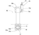
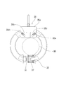
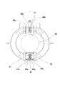
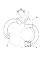
- FIG. 1 is a front view of a current transformer according to a first embodiment of the present invention. It is a rear view of the current transformer which concerns on the 1st Embodiment of this invention.
- 1 is a plan view of a current transformer according to a first embodiment of the present invention. It is a partially cutaway right side view of the current transformer according to the first embodiment of the present invention.
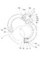
- FIG. 3 is an explanatory diagram of a split core opening state in the current transformer according to the first embodiment of the present invention. It is explanatory drawing of a connection part insertable state of the both ends of one division
- segmentation core edge part in the current transformer which concerns on the 3rd Embodiment of this invention. It is end face contact state explanatory drawing of both the split cores in the current transformer which concerns on the 3rd Embodiment of this invention. It is explanatory drawing of a connection part insertable state of the both ends of one division
- FIG. 6 is an explanatory diagram of a split core opening state in a current transformer according to another embodiment of the present invention. It is explanatory drawing of the connection part insertion possible state of one division
- the current transformer 1 includes a pair of divided cores 11 and 12 each having a shape obtained by dividing a continuous annular body into two parts, and wound around each of the divided cores 11 and 12, respectively.
- a lead wire 16 connected and drawn out from the hinge portion 15, and two cylindrical connection portions 17 in which one end portions and the other end portions of the divided cores 11 and 12 can be inserted into and removed from the inside of the cylinder, respectively.
- the sealing body 18 made of an annular elastic material and the both ends of each of the split cores 11 and 12 are inserted into the respective connecting portions 17 respectively at two predetermined positions on the inner circumferential side of the respective connecting portions 17.
- Split in an annularly closed state A configuration and a fastening member 19 as the fixing member on the outside of the A 11 and 12 and connecting portion 17 is capable of winding disposed detachably.
- the split cores 11 and 12 are semi-annular rings formed of a magnetic material having a high saturation magnetic flux density and high magnetic permeability, such as silicon steel, and an annular body having a substantially square cross-sectional shape divided into two equal parts. It is the structure made into a shape.
- a coil 13 is wound around each of the split cores 11, 12, and a pair of split cores 11, 12 whose outer surfaces are covered with an exterior body 14 are connected via a hinge portion 15. And treated as one.
- the exterior body 14 is made of a waterproof and insulating material, and the outer peripheral surface portion of the split cores 11 and 12 other than both end faces facing the other split cores, and the wound coil. 13 is covered and isolated from the outside.
- the exterior body 14 includes an end cover portion 14a that covers a predetermined range near the both end surfaces of each of the split cores 11 and 12, and an intermediate cover portion 14b that covers an intermediate portion between the end cover portions 14a. is there.
- the end cover portion 14a has a cylindrical portion 14c located near the end faces of the split cores 11 and 12, and a flange portion 14d that is shaped like a bowl extending from the cylindrical portion 14c and is adjacent to the intermediate cover portion 14b.
- the cylindrical cores 14c are fixedly disposed at both end portions of the split cores 11 and 12 so that the columnar direction of the columnar portion 14c is parallel to each other.
- the intermediate cover part 14b is formed separately from the end cover part 14a and covers the intermediate part of the split cores 11 and 12 and the coil 13 wound around the split cores. After the end cover portions 14a are attached to both ends of the core 12, the resin material (plastic or elastomer) forming the intermediate cover portion is placed in a covering state by molding the core intermediate portion and the coil 13 that are exposed. It is the structure formed.
- the intermediate cover portion 14b of the exterior body 14 is formed as an integrated waterproof structure having no seam by molding, but in addition to this, the waterproof performance at the joint portion of a plurality of members is sufficiently ensured.
- the intermediate cover portion may be formed by combining a plurality of cover members.
- the hinge part 15 has a hinge part main body 15a formed by arranging two connecting hole parts 15b and 15c, which are long holes of a predetermined length, in the hole longitudinal direction, and a hole longitudinal direction with respect to the connecting hole parts 15b and 15c.
- the structure includes two support shafts 15d and 15e that are inserted so as to be movable in a direction and rotatable, respectively, and support the divided cores 11 and 12.
- the support shafts 15d and 15e of the hinge portion 15 are connected and fixed to the flange portion 14d of the end cover portion 14a on the one end side of the split core of the exterior body 14 that covers the split cores 11 and 12, and the support shafts 15d and 15e and the split core 11 and 12 are integrated to each other, so that the divided cores 11 and 12 are integrally connected via the hinge portion 15.
- the support shafts 15d and 15e integrated with the split cores 11 and 12 are inserted and supported in the connecting holes 15b and 15c of the hinge main body 15a, so that the split cores 11 and 12 are hinge portions of the hinge portion 15. It can move linearly and rotate with respect to the main body 15a. Based on this, the hinge portion 15 enables the pair of split cores 11 and 12 to be opened and closed by relative rotation with respect to one of the other, and the pair of split cores 11 and 12 are linearly relative to each other. It is a mechanism that allows movement.
- the two connecting holes 15b and 15c of the hinge part body 15a in the hinge part 15 are both formed as long holes arranged in the longitudinal direction of the hole, and with respect to these connecting holes 15b and 15c.
- the support shafts 15d and 15e are configured to be inserted and disposed so as to be movable and rotatable in the longitudinal direction of the holes.
- the present invention is not limited to this. Only one of the two connecting hole portions of the hinge main body is a long hole, and the other connecting hole portion is not arranged in the direction (see, for example, FIGS. 12 and 13). It does not matter as a configuration in which the support shaft to be inserted is simply a hole that rotatably supports the shaft.
- the pair of split cores are allowed to move relative to each other, the combination of the connecting hole portion, which is a long hole in the hinge portion, and the support shaft inserted therein is only one set, and the pair of split cores
- the support shaft of the hinge part is connected and fixed to the end of the exterior body covering the split core, and the hinge part and one split core are connected while the other split core is connected.
- It can also be set as the structure connected with the hinge part main body of a hinge part in a fixed state. Even in this case, the pair of split cores can be opened and closed by moving and rotating relative to the other split core fixed to the hinge portion within the movable range of the support shaft based on the connecting hole.
- the end portion of the split core can be inserted / removed without difficulty with respect to each connecting portion.
- a lead wire 13a that is electrically connected to the coil 13 and passes through the interior of the exterior body 14 and is finally drawn out from the flange 14d of the exterior body 14 is introduced and connected to the hinge body 15a of the hinge section 15. Yes.
- the lead wire 13a is electrically connected inside the hinge portion main body 15a to a lead wire 16 which is separately drawn from the hinge portion main body 15a and connected to an external device. Note that the lead wire 13a is not shown except for main drawings such as a front view relating to the appearance of the current transformer.
- the lead wire 13a between the outer body collar portion 14d and the hinge portion main body 15a is: Since the relative positional change between the flange 14d and the hinge main body 15a is small, it is hardly affected by a change in tension or the like. Thus, even if the coil 13 is wound around both the split cores 11 and 12 and the lead wire 13a is connected to the hinge portion 15, the problem is unlikely to occur. Thus, a wide winding width that effectively utilizes the core magnetic path length can be secured, and if the number of winding layers of the coil is reduced correspondingly, the thickness of the coil portion in the transformer can be reduced, leading to miniaturization of the transformer.
- the connecting portion 17 is configured as a cylindrical member having an inner diameter slightly larger than the columnar portion 14c in the end cover portion 14a of the exterior body 14 that covers the divided cores 11 and 12.
- the connecting portion 17 is a portion in the range from the cylindrical portion 14c of the exterior body end cover portion 14a to the core end surface at the end portion of each of the split cores 11 and 12, that is, the end side from the flange portion 14d of the end cover portion 14a.
- the portions located at the end of the cylinder are inserted into the inside of the cylinder from the openings at both ends of the cylinder forming the connecting portion 17, and the end surfaces of the split cores 11 and 12 are configured to be just in contact with each other.
- continuous grooves 17a for inserting annular seal bodies 18 are drilled at two locations in the vicinity of both ends in the cylinder continuous direction on the inner peripheral side of each connecting portion 17.
- the two connecting portions 17 can be inserted into and removed from the openings at both ends of the cylinder, respectively, at one end portions and the other end portions of the split cores 11 and 12.
- the pair of split cores 11 and 12 can be closed in a ring shape.
- the flange portion 14d of the exterior body end cover portion 14a cannot be inserted into the connection portion 17, and the end portion of the split core is inserted into the connection portion beyond the cylindrical portion 14c of the end cover portion 14a. That is, excessive insertion into the connecting portion 17 can be reliably prevented.
- the seal body 18 is an annular body made of an elastic material such as an O-ring, for example, and is inserted into two grooves 17a in the vicinity of both ends in the cylinder continuous direction on the cylinder inner peripheral side of each connection portion 17, respectively. 17 is arranged along the inner peripheral surface of 17.
- the sealing body 18 is located between the inner peripheral portion of the connecting portion 17 and the outer peripheral portion of the outer cylindrical portion 14c in a state where the end portions of the respective split cores 11 and 12 are inserted into the connecting portion 17 together with the outer casing 14.
- the elastic member is brought into close contact with the connecting portion 17 and the exterior cylindrical portion 14c while being elastically deformed, thereby preventing water from entering the end faces of the split cores 11 and 12 within the connecting portion 17. .
- the simple waterproof structure using the sealing body 18 and the connecting portion 17 enables the split cores 11 and 12 to be made of a uniform material up to their end surfaces, such as silicon steel having a high saturation magnetic flux density and high permeability. Therefore, the transformer can be reduced in size and weight as a whole, and an inexpensive material (for example, silicon steel) that is easily rusted can be used as the split core. In this case, the product cost can be reduced.
- the fastening body 19 is configured to connect a band-like body such as an elastically deformable metal member in an annular shape, and to adjust the length of the annular portion, and to tighten an object positioned on the inside.
- the ends of the split cores 11 and 12 are inserted into the part 17 together with the exterior body 14, and the pair of split cores 11 and 12 are annularly closed so as to surround the split cores 11 and 12 and the outside of the connection part 17. It is the structure which is provided, is clamped from the outside, and presses a pair of division
- the fastening body 19 presses the pair of split cores 11 and 12 from the outside the end surfaces of the pair of split cores 11 and 12 can be held in close contact as the fixture.
- each of the split cores 11 and 12 and the hinge portion 15 are arranged near the electric wire 60 so that the electric wire 60 is positioned between the pair of open split cores 11 and 12 (see FIG. 5). Then, one split core is rotated with respect to the other so that the end of the split core 11 faces the opening of each connecting portion 17 (see FIG. 6). At that time, the rotation of the support shafts 15d and 15e in the connecting holes 15b and 15c of the hinge portion 15 allows the split cores 11 and 12 to rotate, and the end faces of the split cores face each other without difficulty. Can be in a state.
- the sealing body 18 closely contacts the inner peripheral surface of the connecting portion 17 and the outer surface of the outer cylindrical body portion 14c outside the split core end portion without any gap, thereby preventing moisture from entering the core end surface side. Will be.
- a fastening body is formed around the annular portion including the pair of split cores 11 and 12 and the two connection portions 17. 19 is disposed and tightened, and the split core is pressed and held by the fastening body 19 so that the split cores 11 and 12 do not move to the side where the split cores 11 and 12 come out of the connecting portion 17 and the end face contact state is released.
- the fastening body 19 is in a fixed installation state so as not to be easily detached from the outside of the split cores 11 and 12 and the connection portion 17 (see FIGS. 1 and 2), the transformer installation is completed.
- the pair of split cores 11 and 12 connected to be able to be opened and closed by the hinge portion 15 are inserted into the cylindrical connection portion 17 by inserting the end portions of the split core into an annular shape.
- the cylindrical portion 14c in which the outer casing 14 at the ends of the split cores 11 and 12 has a cylindrical shape can be inserted into and removed from the inner side of the connecting portion 17, and the cylindrical inner surface of the facing connecting portion 17 and the outer casing 14 Since sealing is performed using an annular sealing body 18 between the outer surface of the cylindrical portion 14c, the sealing body 18 is elastically deformed and is brought into close contact with the connecting portion 17 and the exterior cylindrical portion 14c, thereby easily providing a waterproof state.
- the structure of each part relating to waterproofing can be simplified to reduce the size and weight of the transformer, and the manufacturing cost can be reduced.
- the connecting portion 17 can be inserted into and removed from the core end portion and the exterior body 14, and only the linear movement of the divided cores 11 and 12 is allowed in the inserted state, so that the fixing of the divided core to the connecting portion 17 is loosened.
- the split cores 11 and 12 do not come out from the position of the sealing body 18 of the connecting portion 17, the watertight holding state by the sealing body 18 does not change, the waterproof performance can be maintained, the core deterioration due to moisture can be prevented, and The insulation state of the electric circuit can be secured.
- the split cores 11 and 12 can be smoothly opened and closed to the installation object such as an electric wire. Can be quickly arranged and removed, and workability can be improved.
- the fastening body 19 as a fixture is connected in an annular shape to an elastically deformable belt-like body, and the length of the annular portion can be adjusted, and the fastening body 19 is in an annularly closed state.
- the pair of split cores 11 and 12 and the connecting portion 17 are arranged so as to be tightened from the outside, and the pair of split cores 11 and 12 are configured to press from the outside in a direction approaching each other.
- Other fixing tools such as a set of bolts and nuts can be adopted as long as the end faces in 12 can be held in close contact with each other. For example, as shown in FIG.
- a band-shaped fastening body 19 that tightens the pair of split cores 11 and 12 and the connection portion 17 from the outside.
- the split core is a hinge part that allows linear relative movement to approach and separate from each other, and the end of the split core is inserted into the connecting part by linear movement. After that, when the end faces of the split cores finally come into contact with each other, the reversible transition to a state in which relative movement between the split cores is not allowed, and the end faces of the pair of split cores are held in close contact with each other It can also be.
- the end surfaces of the split cores 11 and 12 abut on the support shafts 15d and 15e integrated with the split cores 11 and 12 in the hinge part 15.
- a predetermined mechanism that can restrict the movement of the support shafts 15d and 15e in the hole longitudinal direction in the connecting holes 15b and 15c can be provided.
- the support shafts 15d and 15e are held as they are at the support shaft positions in the connecting holes 15b and 15c when the end surfaces of the split cores 11 and 12 come into contact with each other, the support shaft 15d and
- the connection holes 15b and 15c are provided. It is also possible to employ a mechanism that is provided on the hinge body 15a side and that restricts the movement of the support shafts 15d and 15e, such as partially blocking.
- a fixing tool for holding the divided cores is provided. This eliminates the need for fixing the fixture and reduces the cost for installing the current transformer.
- the rotation of the support shafts 15d and 15e is also restricted at the same time. Further, it is possible to suppress rattling and displacement in the closed state of the split core due to a dimensional error or the like, which is more preferable.
- the groove 17a is formed in two locations near the both ends in the cylinder continuous direction on the cylinder inner peripheral side of each connection portion 17 into which each end portion of the pair of split cores 11 and 12 is inserted.
- the present invention is not limited to this, and instead of the arrangement on the side of the connecting portion, as shown in FIG. It can also be set as the structure which provides the sealing body 18a in the exterior body cylinder part 14c side of an edge part.
- a circumferentially continuous groove 14f is provided in the outer cylindrical body portion 14c at the end of each of the split cores 11 and 12, and a sealing body 18a made of an annular elastic material is inserted and disposed in the groove 14f.
- the sealing body 18a is interposed between the inner peripheral portion of the connecting portion 17 and the outer peripheral portion of the outer cylindrical portion 14c with the end portions of the respective split cores 11 and 12 inserted into the connecting portion 17 together with the outer casing 14.
- the sealing body 18a is positioned to be in close contact with the connecting portion 17 and the exterior cylindrical portion 14c without any gap while being elastically deformed, and water enters the end face side of the split cores 11 and 12 within the connecting portion 17. Can be surely prevented.
- the current transformer 2 includes a pair of split cores 21 and 22, a coil 23, exterior bodies 24 and 27, a hinge portion 25, and a lead wire 26 as in the first embodiment. And a fastening body 29, and as a different point, two cylindrical connecting portions 27a are arranged as part of the outer body 27 that covers the divided core 21 at both ends of the one divided core 21, One end portion and the other end portion of the other split core 22 can be inserted into and removed from the inside of the cylinder, respectively, and a sealing body 28 made of an annular elastic material is arranged only at one location on the inner peripheral side of each connecting portion 27a. It has the structure provided.
- the split cores 21 and 22, the coil 23, the exterior body 24, the hinge portion 25, the lead wire 26, and the fastening body 29 have the same configuration as that of the first embodiment, and a description thereof is omitted. To do.
- the configuration of the exterior body 27 other than the end portion where the connection portion 27a on the one split core 21 side is provided is the same configuration as in the first embodiment, and a detailed description of the configuration will be given. Omitted.
- the exterior body 27 covers the outer peripheral surface portions of the one split core 21 other than both end faces facing the other split core 22 and the coil 23 and isolates them from the outside. To do. However, as a different point, in place of the end cover portion 14a forming a part of the exterior body 14 in the first embodiment, a connection portion corresponding to a combination of this end cover portion and the connection portion of the cylindrical member. 27a. That is, the exterior body 27 is configured to include a connection portion 27a that covers a predetermined range portion before and after both end faces of the split core 21, and an intermediate cover portion 27b that covers an intermediate portion between the connection portions 27a.
- the connecting portion 27a covers a predetermined range near the end surface of the split core 21 and is adjacent to the intermediate cover portion 27b, and a cylindrical portion formed as a cylindrical portion that protrudes forward from the base portion 27c to the end face of the split core 21. 27d, and fixedly disposed at both end portions of the split core 21 so that the cylindrically continuous directions of the cylindrical portion 27d are parallel to each other.
- the cylindrical portion 27d of the connecting portion 27a is a portion in the range from the columnar portion 24c of the exterior body end cover portion 24a to the core end surface at the end portion of the split core 21, that is, closer to the end side than the flange portion 24d of the end cover portion 24a.
- the portion to be positioned is inserted into the inside of the cylinder from the opening of the cylindrical portion 27d, and the end surfaces of the split cores 21 and 22 are configured to have a length that enables just abutment.
- the connecting portions 27a at both ends of the split core 21 can be inserted into and removed from the openings of the cylindrical portion 27d at both ends of the other split core 22, respectively.
- the pair of split cores 21 and 22 can be closed in a ring shape.
- the intermediate cover portion 27b is formed separately from the connection portion 27a and covers the intermediate portion of the split core 21 and the coil 23 wound around the intermediate core portion.
- the intermediate cover portion 27b is specifically configured in the first embodiment. After attaching the connecting portions 27a to both ends of the split core 21 in the same manner as in the intermediate cover portion, the resin material forming the intermediate cover portion is placed in a covering state by molding to the exposed core intermediate portion and the coil 23. It is the structure formed.
- the sealing body 28 is an annular body made of an elastic material such as an O-ring, for example, and is provided at a predetermined location near the end in the cylindrical continuous direction on the inner peripheral side of the cylindrical portion 27d of each connecting portion 27a of the exterior body 27. It is the structure which is inserted in the groove
- the sealing body 28 is positioned between the inner peripheral portion of the cylindrical portion 27d of the connecting portion 27a and the outer peripheral portion of the outer cylindrical portion 24c, with the end portion of the split core 22 inserted into the connecting portion 27a together with the outer casing 24. Thus, it is made to closely contact with the connecting portion cylindrical portion 27d and the exterior body column portion 24c with elastic deformation, and prevents water from entering the end faces of the split cores 21 and 22 within the connecting portion 27a. It becomes.
- both end portions of the other split cores 22 are removed from the connection portions 27a at both ends of the split core 21 in advance, and one split core is moved linearly with respect to the other and / or if necessary.
- the divided cores 21 and 22 are opened by being rotated.
- the split cores 21 and 22 and the hinge portion 25 are arranged near the electric wire 60 so that the electric wire 60 is positioned between the pair of open split cores 21 and 22. Then, one split core is rotated with respect to the other so that the end of the split core 22 faces the opening of each connecting portion 27a of the split core 21 (see FIG. 11).
- the sealing body 28 comes into close contact with the inner peripheral surface of the connecting portion cylindrical portion 27d at both ends of the split core 21 and the outer surface of the outer cylindrical portion 24c at the outer end of the split core 22 without any gaps, so It will prevent entry into the end face side.
- the end surfaces of the split cores 21 and 22 are in contact with each other.
- the fastening body 29 is disposed around the annular portion including the pair of split cores 21 and 22.
- the split core 22 is pressed and held by the fastening body 29 so that the split core 22 does not move to the side where the split core 21 is removed from the connecting portion 27a and the end surface contact state is not released.
- the fastening body 29 is in a fixed installation state so as not to be easily detached from the outside of the split cores 21 and 22 (see FIG. 10), the transformer installation is completed.
- the pair of split cores 21 and 22 connected to be able to be opened and closed by the hinge portion 25 are connected to the connection cylindrical portion 27d at both ends of the split core 21 and the other split core end portions.
- the outer body cylindrical portion 24c at the end of the split core 22 can be inserted into and removed from the inside of the connecting portion cylindrical portion 27d at the end of the split core, and the connecting portion cylindrical portion 27d Since sealing is performed using an annular seal body 28 between the inner peripheral surface and the outer peripheral surface of the exterior body cylindrical portion 24c, the connecting portion cylindrical portion 27d and the exterior body cylindrical portion 24c are elastically deformed while the seal body 28 is elastically deformed.
- the waterproof state can be easily secured by being in close contact with each other, the structure of each part relating to waterproofing can be simplified, the transformer can be reduced in size and weight, and the manufacturing cost can be reduced.
- two connecting portions 27a are disposed at both ends of one divided core 21 as a part of the outer package 27 that covers the divided core 21, and the other divided core 22
- the pair of split cores 21 and 22 are closed in an annular shape.
- the present invention is not limited to this, and a connection portion is provided for each of the pair of split cores, that is, a connection portion is provided at each of one end portion of one split core and the other end portion of the other split core.
- One end of the other split core can be inserted into and removed from the connection of one split core, and the other end of one split core can be inserted into and removed from the connection of the other split core.
- Separate split at connection A pair of split cores can also be configured to be annularly inserted by respectively inserting corresponding end portions of the core, and the split core end faces are brought into contact with each other in the closed state of the pair of split cores as in the above embodiment.
- the sealing body positioned between the connection portion and the exterior body can be brought into close contact with the connection portion and the exterior body while being elastically deformed, so that a waterproof state can be easily secured.
- the outer cylindrical body portions 14c and 24c at the ends of the split cores 11, 12, and 22 are inserted into the cylindrical connection portions 17 and 27a.
- the sealing bodies 18 and 28 attached to the inner peripheral part of the connection parts 17 and 27a or the outer peripheral part of the outer cylinder part 14c and 24c are brought into close contact with the connection parts 17 and 27a and the outer cylinder part 14c and 24c without any gaps.
- water is prevented from entering the end faces of the split cores 11, 12, 21, and 22.
- the present invention is not limited to this.
- the end portion of the exterior body covering the portion is formed into a cylindrical shape with an opening shape similar to the cross-sectional shape of the cylindrical shape of the connection portion, and the end portion of the split core is inserted into the connection portion.
- the sealing body is positioned between the outer peripheral portion of the connecting portion and the inner peripheral portion of the outer casing end located outside the connecting portion. It can also be set as the structure which maintains the watertight state between exterior bodies.
- an annular seal body is inserted and disposed in a groove formed in the outer peripheral portion of the connection portion, or an annular seal is formed in the groove formed in the cylindrical inner peripheral portion of the exterior body end portion at the split core end portion.
- the body is inserted and disposed, and the seal body is attached to the connection portion or the exterior body, so that the end portion of the split core is inserted into the connection portion, and the outer peripheral portion of the connection portion and the inner peripheral portion of the exterior body end portion
- the seal body is positioned between the two and the seal body, and the seal body is brought into close contact with the connecting portion and the exterior body cylindrical portion without any gaps, so that water can be reliably prevented from entering the connecting portion.
- the end portion of the exterior body in the configuration example in the tubular shape includes the case where the end portion of the exterior body on the other end side of the split core is similarly tubular (the connection portion is a part of the exterior body). ), It is formed so that the direction of the other end and the cylindrical continuous shape are parallel to each other, and conversely, when the other end is a column, Are formed so as to be parallel to a direction continuous to the end and a direction continuous to the cylindrical shape of the end.
- the pair of split cores is configured to be formed as a shape in which an annular body is equally divided into two, but the present invention is not limited to this.
- the continuous substantially annular body is divided into two parts, for example, an elliptical or oval (for example, see FIG. 14 to FIG. 16) annular body, a semicircular shape, A shape in which two divided cores having completely different shapes, such as a combination of one divided core having a substantially U shape and the other divided core having a substantially I shape, are joined together in a substantially annular shape to obtain a continuous state. It can also be set as the structure formed as.
- the two connecting hole portions in the hinge portion are formed so as to be arranged side by side in the hole longitudinal direction.
- the connecting holes 35 b and 35 c of the hinge portion 35 can be arranged in an inverted eight-letter shape (a shape that widens upward toward the end).
- the hinge is applied by pushing the hinge portion 35 upward.
- Part 35 and connection part 37 When the relative movement in the vertical direction is caused between the two, the ends of the split cores 31 and 32 that face each other are linearly moved so as to approach each other (see FIG. 13), and the ends of the split cores 31 and 32 are connected to the connecting portion.
- the movement to be inserted into 37 can be easily generated without operating the split cores 31 and 32.
- the current transformer In a state where the current transformer is installed around the electric wire 60, the current transformer is subjected to a relatively upward force from the electric wire 60 when a load of the current transformer is applied to the electric wire 60. For this reason, when the hinge part 35 is located in the upper part of the current transformer and is on the upper side of the electric wire 60, the hinge part 35 receives an upward force from the electric wire 60, and is hardly displaced downward with respect to the connection part 37. The movement of the split cores 31 and 32 in the direction away from each other due to the relative movement of the connection portion 37 with respect to the connection portion 37 is prevented, and the pair of split cores 31 and 32 are closed in an annular shape while their end faces are in contact with each other. The state where it was installed around 60 can be maintained.
- the hinge portion 35 in the current transformer is on the lower side of the electric wire 60, the hinge portion 35 is applied with its own load (self-weight), so that it is not easily displaced with respect to the connection portion 37, and the split core 31. , 32 are not caused to move away from each other.
- the split cores 31 and 32 are in contact with each other.
- the support shafts 35d and 35e integrated with 32 are located at the lower ends (positions where the coupling holes are closest to each other) of the coupling holes 35b and 35c of the hinge body 35a. Based on this, when the support shafts 35d, 35e reach this position, the movement of the support shafts 35d, 35e in the connecting holes 35b, 35c is automatically restricted, so that the support shafts 35d, 35e A predetermined mechanism for holding the position may be provided.
- the outer peripheral surface of the outer cylindrical body portion of the split core end portion and the inner peripheral surface of the connection portion are formed as a simple cylindrical outer peripheral surface or a cylindrical inner peripheral curved surface shape.
- the split core 41 is formed on the outer peripheral cylindrical portion 44 c at the end of each split core 41, 42. , 42 are provided with male screw portions 44e having different orientations, and two female screw portions 47b having different orientations, which are respectively engaged with the male screw portions 44e on the divided core side, in part of the cylindrical inner peripheral portion of the connection portion 47.
- the connecting portion 47 can also be set as the structure provided.
- the connecting portion 47 is disposed so as to be linearly movable and rotatable outside the end of one split core 42 (see FIG. 14)
- the end of the other split core 41 is also inserted into the connecting portion 47.
- the split cores are brought close to each other until the male threaded portion 44e of the exterior cylindrical portion 44c at the end of each split core reaches the vicinity of the female threaded portion 47b (see FIG. 15), and the connecting portion 47 is brought to the end of the split cores 41 and 42.
- the hinge portion 15 can rotate and linearly move the support shafts 15d and 15e connected and integrated with the divided cores 11 and 12 with respect to the hinge portion main body 15a.
- the pair of split cores 11 and 12 are allowed to rotate with respect to one of the other and linear movement that approaches and separates from each other by being fixed to the hinge support shafts 15d and 15e.
- the present invention is not limited to this.
- a hinge part main body 55a of the hinge part 55 is combined with a plurality of members, and a part 55b of the hinge part main body 55a is combined.
- the movable portion is rotatable with respect to the other portion 55c, and one split core 51 is provided on the part 55b of the hinge portion main body 55a, and the other portion 55c is provided on the other portion.
- the split core 52 while intervening directly or other movable member, respectively, may be a linearly movably connected to configure.
- a part of the hinge part main body has a movable structure that can move linearly with respect to the other part, and one of the split cores is directly connected to the part of the hinge part main body, and the other of the split cores is directly connected to the other part. Or it can also be set as the structure connected so that rotation is possible, interposing another movable member.
- the pair of split cores can be connected to each other so that they can rotate and move linearly.
- the open / close and end portions of the split cores when installed around the electric wire or cable are used. Insertion into and removal from the connecting part can be performed smoothly.
- connection portion is cylindrical, and the seal body is also formed in an annular shape, and the end of the exterior body is also formed in a columnar shape.
- the present invention is not limited to this, and the connecting portion is formed in a cylindrical shape other than a cylinder, for example, the connecting portion 57 is formed in a rectangular tube shape as shown in FIG. It can also be set as the structure which employ
- the cylindrical shape of the connecting portion is not limited to a cylindrical body having an outer shape similar to the cross-sectional shape of the inner through-hole portion, the end of the split core can be inserted into and removed from the connecting portion, and If the end of the exterior body is cylindrical, the end of the connection can be inserted, or if the end of the exterior body is columnar, this can be inserted into the interior of the connection.
- a cylindrical shape in which the cross-sectional shape of the hole is different from the cross-sectional shape of the outer shape for example, a shape in which the inner through-hole is a circular cross section and the outer shape is a square cross section may be used.
Landscapes
- Engineering & Computer Science (AREA)
- Power Engineering (AREA)
- Physics & Mathematics (AREA)
- General Physics & Mathematics (AREA)
- Transformers For Measuring Instruments (AREA)
- Measuring Instrument Details And Bridges, And Automatic Balancing Devices (AREA)
Abstract
Description
以下、本発明の第1の実施形態を前記図1ないし図7に基づいて説明する。
前記各図において本実施形態に係るカレントトランス1は、連続する円環状体を二つに分割した形状とされる一対の分割コア11、12と、各分割コア11、12の周りにそれぞれ巻回配設されるコイル13と、各分割コア11、12及びコイル13を覆う外装体14と、一対の分割コア11、12を開閉可能に連結一体化するヒンジ部15と、コイル13と電気的に接続され、ヒンジ部15から引き出される引出線16と、各分割コア11、12の一端部同士、及び他端部同士をそれぞれ筒内側に挿脱可能とされる円筒状の二つの接続部17と、これら各接続部17の円筒内周側における所定の二箇所に配設される円環状弾性材製のシール体18と、各分割コア11、12両端部を各接続部17にそれぞれ挿入して環状に閉じた状態の分割コア11、12及び接続部17の外側に着脱可能に巻回配設される前記固定具としての締結体19とを備える構成である。
本発明の第2の実施形態を前記図10及び図11に基づいて説明する。
前記各図において本実施形態に係るカレントトランス2は、前記第1の実施形態同様、一対の分割コア21、22と、コイル23と、外装体24、27と、ヒンジ部25と、引出線26と、締結体29とを備える一方、異なる点として、円筒状の二つの接続部27aが、一方の分割コア21の両端部でこの分割コア21を覆う外装体27の一部として配設され、他方の分割コア22の一端部と他端部をそれぞれ筒内側に挿脱可能とされると共に、円環状弾性材製のシール体28が各接続部27aの円筒内周側における一箇所のみに配設される構成を有するものである。
すなわち、外装体27は、分割コア21の両端面前後所定範囲部分をそれぞれ覆う接続部27aと、この接続部27a間の中間部分を覆う中間カバー部27bとを備える構成である。
分割コア22両端における円柱部24cの部分を全て分割コア21側の接続部円筒部27dに挿入すると、分割コア21、22の端面同士が当接した状態が得られる。
前記第1及び第2の各実施形態に係るカレントトランスにおいては、ヒンジ部における二つの連結用孔部を、孔長手方向に並ぶ配置として穿設する構成としているが、この他、第3の実施形態として、図12及び図13に示すように、ヒンジ部35の連結用孔部35b、35cを倒立八の字状(上向きに末広がりとなる形状)に配置する構成とすることもでき、この場合、分割コア31端部の接続部37への挿入に係る各分割コア31、32の直線移動の際に、同時にヒンジ部本体35aも接続部37に対し前記直線移動の向きと異なる方向に相対移動するようになることを利用して、例えば、接続部37を挟んで分割コア31、32端部を正対させた状態(図12参照)で、ヒンジ部35を上方に押す力を加えてヒンジ部35と接続部37との間に上下方向の相対移動を生じさせると、正対させた分割コア31、32端部が互いに近付くように直線移動することとなり(図13参照)、分割コア31、32端部を接続部37に挿入する動きを分割コア31、32の操作なしに簡易に生じさせることができる。
前記第1及び第2の各実施形態に係るカレントトランスにおいて、分割コア端部の外装体円柱部の外周面や接続部の内周面は、単純な円柱外周や円筒内周の曲面形状として形成する構成としているが、この他、第4の実施形態として、図14ないし図16に示すように、各分割コア41、42端部の外装体円柱部44cの一部外周面に、分割コア41、42同士で向きの異なる雄ねじ部44eを設けると共に、接続部47の円筒内周部の一部に、各分割コア側の雄ねじ部44eにそれぞれ螺合する、向きの異なる二つの雌ねじ部47bを設ける構成とすることもできる。この場合、例えば、一方の分割コア42端部の外側に接続部47が直線移動且つ回転可能に配置されている状態(図14参照)から、他方の分割コア41端部も接続部47に挿入し、各分割コア端部における外装体円柱部44cの雄ねじ部44eが雌ねじ部47b近傍に達するまで分割コア同士を近付け(図15参照)、さらに、接続部47を分割コア41、42端部に対し所定方向に回転させると、雄ねじ部44eと雌ねじ部47bの螺合に伴って、各分割コア41、42端部に接続部47内へ進む動きのみ許容する状態が生じて、コア端面を確実に突き合わせて当接させることができる(図16参照)。そして、接続部47を各分割コア41、42に対し前記と逆向きに回転させない限りは、螺合状態が継続して、分割コア41、42端部の接続部47から抜脱する向きの動きを抑えることができ、分割コア端面同士の接合状態をより確実に維持できる。
また、前記第1の実施形態に係るカレントトランスにおいて、ヒンジ部15は、ヒンジ部本体15aに対し、各分割コア11、12と連結一体化される支持軸15d、15eをそれぞれ回転且つ直線移動可能に配設した構造であり、このヒンジ部支持軸15d、15eへの取付固定によって、一対の分割コア11、12は、その一方の他方に対する回転と、互いに接近及び離隔する直線移動とを許容されつつ連結される構成としているが、これに限られるものではなく、例えば、図17ないし図19に示すように、ヒンジ部55のヒンジ部本体55aを、複数部材の組合せにより、その一部55bを他部55cに対し回転可能な可動構造とすると共に、ヒンジ部本体55aの前記一部55bに一方の分割コア51を、前記他部55cに他方の分割コア52を、それぞれ直接又は他の可動部材を介在させつつ、直線移動可能に連結する構成とすることもできる。この他、ヒンジ部本体の一部を他部に対し直線移動可能な可動構造とし、ヒンジ部本体の前記一部に対し分割コアの一方を、前記他部に対し分割コアの他方を、それぞれ直接又は他の可動部材を介在させつつ、回転可能に連結する構成とすることもできる。こうした各構成によっても、一対の分割コアを互いに対する回転と直線移動とが可能な連結状態にでき、前記実施形態同様、各分割コアの電線又はケーブル周囲への設置の際の開閉と端部の接続部への挿脱がスムーズに行える。
11、12、21、22 分割コア
13、23 コイル
13a リード線
14、24、27 外装体
14a、24a 端カバー部
14b、24b、27b 中間カバー部
14c、24c 円柱部
14d、14e、24d 鍔部
14f 溝
15、25 ヒンジ部
15a ヒンジ部本体
15b、15c 連結用孔部
15d、15e 支持軸
16、26 引出線
17、27a 接続部
17a、27e 溝
18、18a、28 シール体
19、29 締結体
19a ボルト
19b ナット
27c 基部
27d 円筒部
31、32 分割コア
35 ヒンジ部
35a ヒンジ部本体
35b、35c 連結用孔部
37 接続部
41、42 分割コア
44c 円柱部
44e 雄ねじ部
47 接続部
47b 雌ねじ部
51、52 分割コア
55 ヒンジ部
55a ヒンジ部本体
55b 一部
55c 他部
60 電線
Claims (7)
- 連続する略環状体を二つに分割した形状とされる一対の分割コアと、当該分割コアの一方又は両方に巻回配設されるコイルと、一対の分割コアを開閉可能に連結一体化するヒンジ部とを少なくとも有し、一対の分割コアを略環状に閉じて生じる中心の貫通孔部に電線又はケーブルが通るようにして、電線又はケーブルの周囲に着脱可能に設けられるカレントトランスにおいて、
前記分割コアにおける、対をなす他の分割コアに面する両端面以外の外周面部分、及び、前記コイルを覆って外部から隔離する、防水性及び絶縁性のある材質製の外装体と、
前記各分割コアの一端部同士、及び他端部同士をそれぞれ筒内側に挿脱可能とされる筒状部材である二つの接続部と、
前記各分割コアの端部を前記接続部内に挿入した状態で、接続部の内周部分と当該接続部に挿入されて接続部内側に位置する外装体端部の外周部分との間、又は、接続部の外周部分と当該接続部端部を挿入させて接続部外側に位置する筒状の外装体端部の内周部分との間に位置するように、接続部又は外装体に取り付けられる環状弾性材製のシール体とを備え、
前記外装体における分割コアの両端面近傍の端部が、挿入される前記接続部の筒内側貫通孔部の横断面形状と相似する外形の柱状とされ、又は、挿入させる接続部の筒外形の横断面形状と相似する開口形状の筒状とされ、
当該外装体の柱状又は筒状とされる両端部同士が、柱状に連続する方向又は筒状に連続する方向を平行とする形状として形成され、
前記ヒンジ部が、一対の分割コア同士が外装体の端部の連続方向を一致させて互いに接近及び離隔する直線的な相対移動を許容するように、各分割コアと連結され、
前記各接続部に各分割コアの端部を挿入して、一対の分割コアを略環状に閉じる状態とされ、当該閉状態で、分割コア端面同士が当接すると共に、前記シール体が弾性変形を伴いつつ接続部及び外装体にそれぞれ隙間なく密着することを
特徴とするカレントトランス。 - 連続する略環状体を二つに分割した形状とされる一対の分割コアと、当該分割コアの一方又は両方に巻回配設されるコイルと、一対の分割コアを開閉可能に連結一体化するヒンジ部とを少なくとも有し、一対の分割コアを略環状に閉じて生じる中心の貫通孔部に電線又はケーブルが通るようにして、電線又はケーブルの周囲に着脱可能に設けられるカレントトランスにおいて、
前記分割コアにおける、対をなす他の分割コアに面する両端面以外の外周面部分、及び、前記コイルを覆って外部から隔離する、防水性及び絶縁性のある材質製の外装体と、
前記分割コアの一方における両端部にそれぞれ配設され、一端部側に他方の分割コアの一端部を、他端部側に他方の分割コアの他端部をそれぞれ筒内側に挿脱可能とされる筒状部分を有する二つの接続部と、
前記他方の分割コアの端部を前記接続部内に挿入した状態で、接続部の内周部分と当該接続部に挿入されて接続部内側に位置する外装体端部の外周部分との間、又は、接続部の外周部分と当該接続部端部を挿入させて接続部外側に位置する筒状の外装体端部の内周部分との間に位置するように、接続部又は外装体に取り付けられる環状弾性材製のシール体とを備え、
前記二つの接続部が、筒内部に一方の分割コアの各端面をそれぞれ位置させつつ、互いに筒状に連続する方向を平行とする配置として配設され、
前記他方の分割コアの外装体における分割コアの両端面近傍の端部が、挿入される前記接続部の筒内側貫通孔部の横断面形状と相似する外形の柱状とされ、又は、挿入させる接続部の筒外形の横断面形状と相似する開口形状の筒状とされ、
当該他方の分割コアの外装体の柱状又は筒状とされる両端部同士が、柱状に連続する方向又は筒状に連続する方向を平行とする形状として形成され、
前記ヒンジ部が、一対の分割コア同士が接続部の連続方向と外装体の端部の連続方向とを一致させて互いに接近及び離隔する直線的な相対移動を許容するように、各分割コアと連結され、
前記各接続部に他方の分割コアの各端部を挿入して、一対の分割コアを略環状に閉じる状態とされ、当該閉状態で、分割コア端面同士が当接すると共に、前記シール体が弾性変形を伴いつつ接続部及び外装体にそれぞれ隙間なく密着することを
特徴とするカレントトランス。 - 連続する略環状体を二つに分割した形状とされる一対の分割コアと、当該分割コアの一方又は両方に巻回配設されるコイルと、一対の分割コアを開閉可能に連結一体化するヒンジ部とを少なくとも有し、一対の分割コアを略環状に閉じて生じる中心の貫通孔部に電線又はケーブルが通るようにして、電線又はケーブルの周囲に着脱可能に設けられるカレントトランスにおいて、
前記分割コアにおける、対をなす他の分割コアに面する両端面以外の外周面部分、及び、前記コイルを覆って外部から隔離する、防水性及び絶縁性のある材質製の外装体と、
一方の分割コアの一端部及び他方の分割コアの他端部にそれぞれ配設され、一方の分割コアの一端部で他方の分割コアの一端部を、他方の分割コアの他端部で一方の分割コアの他端部を、それぞれ筒内側に挿脱可能とされる筒状部分を有する二つの接続部と、
前記各分割コアの端部を前記接続部内に挿入した状態で、接続部の内周部分と当該接続部に挿入されて接続部内側に位置する外装体端部の外周部分との間、又は、接続部の外周部分と当該接続部端部を挿入させて接続部外側に位置する筒状の外装体端部の内周部分との間に位置するように、接続部又は外装体に取り付けられる環状弾性材製のシール体とを備え、
各分割コアの外装体における、接続部が配設されない側の分割コア端面近傍の端部が、挿入される接続部の筒内側貫通孔部の横断面形状と相似する外形の柱状とされ、又は、挿入させる接続部の筒外形の横断面形状と相似する開口形状の筒状とされ、
当該分割コアの外装体の柱状又は筒状とされる端部が、柱状に連続する方向又は筒状に連続する方向を、同じ分割コアに配設される接続部の筒状に連続する方向に対し平行とする形状として形成され、
前記ヒンジ部が、一対の分割コア同士が接続部の連続方向と外装体の端部の連続方向とを一致させて互いに接近及び離隔する直線的な相対移動を許容するように、各分割コアと連結され、
各分割コア端部の接続部に別の分割コアの端部をそれぞれ挿入して、一対の分割コアを略環状に閉じる状態とされ、当該閉状態で、分割コア端面同士が当接すると共に、前記シール体が弾性変形を伴いつつ接続部及び外装体にそれぞれ隙間なく密着することを
特徴とするカレントトランス。 - 前記請求項1ないし3のいずれかに記載のカレントトランスにおいて、
前記ヒンジ部が、所定長さの長孔である連結用孔部を穿設されるヒンジ部本体と、前記連結用孔部に対し孔長手方向に移動可能且つ回転可能に挿入される支持軸とを有し、前記ヒンジ部本体に対して前記連結用孔部と支持軸との組を一又は複数組設けてなり、
一対の分割コアのうち少なくとも一方の分割コアと前記ヒンジ部とが、前記分割コアを覆う外装体の分割コア一端部寄りの所定箇所に前記ヒンジ部の一支持軸を連結固定し、当該支持軸と一体化した前記分割コアを前記ヒンジ部本体に対し移動可能且つ回転可能として、連結されることを
特徴とするカレントトランス。 - 前記請求項1ないし4のいずれかに記載のカレントトランスにおいて、
前記外装体が、両端に位置する柱状もしくは筒状の端部又は接続部と当該柱状もしくは筒状の端部又は接続部に挟まれた中間部分とを別個に形成され、分割コア両端に柱状もしくは筒状の端部又は接続部となる部材を装着後、中間部分を樹脂モールドで成形されてなることを
特徴とするカレントトランス。 - 前記請求項1ないし5のいずれかに記載のカレントトランスにおいて、
前記接続部に分割コアの端部を外装体ごと挿入して、一対の分割コアを略環状に閉じた状態で、一対の分割コアを互いに近付く向きに外側から押圧可能として分割コア近傍に着脱可能に配設され、一対の分割コアにおける一端面同士及び他端面同士を密着状態に保持する固定具を備えることを
特徴とするカレントトランス。 - 連続する略環状体を二つに分割した形状とされる一対の分割コアと、当該分割コアの一方又は両方に巻回配設されるコイルと、一対の分割コアを開閉可能に支持するヒンジ部とを少なくとも有し、一対の分割コアを略環状に閉じて生じる中心の貫通孔部に電線又はケーブルが通るようにして、電線又はケーブルの周囲に着脱可能に設けられるカレントトランスにおいて、
一対の分割コアを略環状に閉じた状態で、一対の分割コアを互いに近付く向きに外側から押圧可能として分割コア近傍に着脱可能に配設され、一対の分割コアにおける一端面同士及び他端面同士を密着状態に保持する固定具を備え、
前記ヒンジ部が、一対の分割コアが一端面同士及び他端面同士をそれぞれ対向させて互いに接近又は離隔する相対直線移動を許容するように、各分割コアと連結されることを
特徴とするカレントトランス。
Priority Applications (4)
| Application Number | Priority Date | Filing Date | Title |
|---|---|---|---|
| JP2018501825A JPWO2017146256A1 (ja) | 2016-02-26 | 2017-02-27 | カレントトランス |
| EP17756690.8A EP3422023A4 (en) | 2016-02-26 | 2017-02-27 | POWER CONVERTER |
| KR1020187021527A KR20180120140A (ko) | 2016-02-26 | 2017-02-27 | 커런트 트랜스포머 |
| CN201780012814.9A CN108700617A (zh) | 2016-02-26 | 2017-02-27 | 电流互感器 |
Applications Claiming Priority (2)
| Application Number | Priority Date | Filing Date | Title |
|---|---|---|---|
| JP2016035292 | 2016-02-26 | ||
| JP2016-035292 | 2016-02-26 |
Publications (1)
| Publication Number | Publication Date |
|---|---|
| WO2017146256A1 true WO2017146256A1 (ja) | 2017-08-31 |
Family
ID=59685398
Family Applications (1)
| Application Number | Title | Priority Date | Filing Date |
|---|---|---|---|
| PCT/JP2017/007539 Ceased WO2017146256A1 (ja) | 2016-02-26 | 2017-02-27 | カレントトランス |
Country Status (5)
| Country | Link |
|---|---|
| EP (1) | EP3422023A4 (ja) |
| JP (1) | JPWO2017146256A1 (ja) |
| KR (1) | KR20180120140A (ja) |
| CN (1) | CN108700617A (ja) |
| WO (1) | WO2017146256A1 (ja) |
Cited By (13)
| Publication number | Priority date | Publication date | Assignee | Title |
|---|---|---|---|---|
| CN109036822A (zh) * | 2018-07-16 | 2018-12-18 | 江阴市星火电子科技有限公司 | 一种户外开合式电流互感器的装配工艺 |
| WO2019089681A1 (en) | 2017-10-31 | 2019-05-09 | ABB Schweiz AB | Submersible split core current sensor and housing |
| JP2019128253A (ja) * | 2018-01-24 | 2019-08-01 | 横河電機株式会社 | 磁気センサ、センサヘッド及び電流センサ |
| CN110648834A (zh) * | 2019-09-29 | 2020-01-03 | 长江勘测规划设计研究有限责任公司 | 巨型水轮发电机出口电流互感器安装结构及方法 |
| WO2020244144A1 (zh) * | 2019-06-04 | 2020-12-10 | 北京航天常兴科技发展股份有限公司 | 一种单元式电流互感器 |
| CN112309693A (zh) * | 2020-11-05 | 2021-02-02 | 珠海菲森电力科技有限公司 | 一种宽线性高精度开合结构零序电流互感器 |
| JP2021050986A (ja) * | 2019-09-24 | 2021-04-01 | 株式会社Wave Energy | 電力計リレー、盤、及び、自家消費型の電力システム |
| CN113053646A (zh) * | 2021-04-06 | 2021-06-29 | 江阴市星火电子科技有限公司 | 一种紧凑型户外开合式电流互感器 |
| CN116344171A (zh) * | 2023-04-18 | 2023-06-27 | 上海卓高电气东台有限公司 | 一种啮齿合开合式互感器铁芯 |
| CN117214567A (zh) * | 2023-08-31 | 2023-12-12 | 国网安徽省电力有限公司涡阳县供电公司 | 一种配电网拓扑结构识别装置 |
| JP2024048976A (ja) * | 2022-09-28 | 2024-04-09 | Tdk株式会社 | コイル装置 |
| KR20240170496A (ko) * | 2024-08-28 | 2024-12-03 | 주식회사 루텍 | 스플릿 타입 계측 장치 |
| WO2026049406A1 (ko) * | 2024-08-28 | 2026-03-05 | 주식회사 루텍 | 스플릿 타입 계측 장치 |
Families Citing this family (8)
| Publication number | Priority date | Publication date | Assignee | Title |
|---|---|---|---|---|
| CN110619998B (zh) * | 2019-07-08 | 2020-10-27 | 河南平高电气股份有限公司 | 屏蔽罩及使用该屏蔽罩的电压互感器 |
| CN110739141A (zh) * | 2019-10-28 | 2020-01-31 | 江苏靖江互感器股份有限公司 | 一种具有高低温误差调节功能的电流互感器 |
| CN110767428B (zh) * | 2019-11-07 | 2020-08-18 | 安徽昭田电子科技有限公司 | 一种磁芯线圈部件以及磁芯的制造方法 |
| CN110690022B (zh) * | 2019-11-11 | 2021-06-08 | 安徽昭田电子科技有限公司 | 一种拼装式磁芯及其生产工艺 |
| WO2021212138A1 (en) * | 2020-04-14 | 2021-10-21 | Magnetics & Controls, Inc. | Split core current transformer and method of making and using same |
| EP3979266B1 (en) | 2020-09-30 | 2024-06-05 | Hitachi Energy Ltd | Support for mounting an accessory equipment assembly to a base of bushing, a corresponding accessory equipment module, and bushing |
| JP7281442B2 (ja) * | 2020-12-14 | 2023-05-25 | 横河電機株式会社 | 分割型センサヘッド及び分割型電流センサ |
| KR102389861B1 (ko) * | 2021-11-08 | 2022-04-22 | 박준철 | 클램프 구조의 변류기 |
Citations (8)
| Publication number | Priority date | Publication date | Assignee | Title |
|---|---|---|---|---|
| JPS5016417U (ja) * | 1973-06-08 | 1975-02-21 | ||
| JPS6119114A (ja) * | 1984-07-06 | 1986-01-28 | Nippon Kinzoku Kk | 変流器 |
| JPH08194014A (ja) * | 1995-01-12 | 1996-07-30 | Ngk Insulators Ltd | 電流検出器 |
| JP2000088889A (ja) * | 1998-09-10 | 2000-03-31 | Tokin Corp | カレントトランスとそれを用いた装置 |
| JP2001297921A (ja) | 2000-04-17 | 2001-10-26 | U R D:Kk | クランプ式トランス用鉄心 |
| JP2010243312A (ja) | 2009-04-06 | 2010-10-28 | U R D:Kk | 電流センサ |
| JP2011158255A (ja) * | 2010-01-29 | 2011-08-18 | Hioki Ee Corp | クランプセンサ |
| WO2016024542A1 (ja) * | 2014-08-12 | 2016-02-18 | アルプス・グリーンデバイス株式会社 | 電流センサ |
Family Cites Families (8)
| Publication number | Priority date | Publication date | Assignee | Title |
|---|---|---|---|---|
| SU1386919A2 (ru) * | 1986-06-23 | 1988-04-07 | Организация П/Я Х-5263 | Бесконтактный датчик тока |
| JP2009063368A (ja) * | 2007-09-05 | 2009-03-26 | Nippon Steel Engineering Co Ltd | 電流測定装置および電流測定方法 |
| US9229036B2 (en) * | 2012-01-03 | 2016-01-05 | Sentient Energy, Inc. | Energy harvest split core design elements for ease of installation, high performance, and long term reliability |
| US20130342188A1 (en) * | 2012-06-21 | 2013-12-26 | Grid Sentry LLC | Disassociated Split Sensor Coil for Power Distribution Line Monitoring |
| CN203118754U (zh) * | 2013-01-22 | 2013-08-07 | 上海雷博司电气股份有限公司 | 用于环网柜的电流互感器 |
| CN103426620B (zh) * | 2013-08-30 | 2015-11-18 | 南京南瑞继保工程技术有限公司 | 开合式电子式电流互感器 |
| CN204479634U (zh) * | 2015-01-28 | 2015-07-15 | 贵州电力试验研究院 | 一种具有集成式一次侧传感单元的全光纤电流互感器 |
| CN204760867U (zh) * | 2015-05-27 | 2015-11-11 | 王海强 | Gis用光纤电流传感器外壳、光纤电流传感器以及gis设备 |
-
2017
- 2017-02-27 WO PCT/JP2017/007539 patent/WO2017146256A1/ja not_active Ceased
- 2017-02-27 EP EP17756690.8A patent/EP3422023A4/en not_active Withdrawn
- 2017-02-27 KR KR1020187021527A patent/KR20180120140A/ko not_active Withdrawn
- 2017-02-27 CN CN201780012814.9A patent/CN108700617A/zh active Pending
- 2017-02-27 JP JP2018501825A patent/JPWO2017146256A1/ja active Pending
Patent Citations (8)
| Publication number | Priority date | Publication date | Assignee | Title |
|---|---|---|---|---|
| JPS5016417U (ja) * | 1973-06-08 | 1975-02-21 | ||
| JPS6119114A (ja) * | 1984-07-06 | 1986-01-28 | Nippon Kinzoku Kk | 変流器 |
| JPH08194014A (ja) * | 1995-01-12 | 1996-07-30 | Ngk Insulators Ltd | 電流検出器 |
| JP2000088889A (ja) * | 1998-09-10 | 2000-03-31 | Tokin Corp | カレントトランスとそれを用いた装置 |
| JP2001297921A (ja) | 2000-04-17 | 2001-10-26 | U R D:Kk | クランプ式トランス用鉄心 |
| JP2010243312A (ja) | 2009-04-06 | 2010-10-28 | U R D:Kk | 電流センサ |
| JP2011158255A (ja) * | 2010-01-29 | 2011-08-18 | Hioki Ee Corp | クランプセンサ |
| WO2016024542A1 (ja) * | 2014-08-12 | 2016-02-18 | アルプス・グリーンデバイス株式会社 | 電流センサ |
Non-Patent Citations (1)
| Title |
|---|
| See also references of EP3422023A4 |
Cited By (19)
| Publication number | Priority date | Publication date | Assignee | Title |
|---|---|---|---|---|
| EP3704498A4 (en) * | 2017-10-31 | 2021-08-18 | ABB Schweiz AG | SUBMERSIBLE GAP CORE CURRENT SENSOR AND HOUSING |
| WO2019089681A1 (en) | 2017-10-31 | 2019-05-09 | ABB Schweiz AB | Submersible split core current sensor and housing |
| US11733272B2 (en) | 2017-10-31 | 2023-08-22 | Abb Schweiz Ag | Submersible split core current sensor and housing |
| JP2019128253A (ja) * | 2018-01-24 | 2019-08-01 | 横河電機株式会社 | 磁気センサ、センサヘッド及び電流センサ |
| JP7061421B2 (ja) | 2018-01-24 | 2022-04-28 | 横河電機株式会社 | 磁気センサ、センサヘッド及び電流センサ |
| CN109036822A (zh) * | 2018-07-16 | 2018-12-18 | 江阴市星火电子科技有限公司 | 一种户外开合式电流互感器的装配工艺 |
| WO2020244144A1 (zh) * | 2019-06-04 | 2020-12-10 | 北京航天常兴科技发展股份有限公司 | 一种单元式电流互感器 |
| JP2021050986A (ja) * | 2019-09-24 | 2021-04-01 | 株式会社Wave Energy | 電力計リレー、盤、及び、自家消費型の電力システム |
| JP7001282B2 (ja) | 2019-09-24 | 2022-02-03 | 株式会社Wave Energy | 電力計リレー、盤、及び、自家消費型の電力システム |
| CN110648834B (zh) * | 2019-09-29 | 2023-01-24 | 长江勘测规划设计研究有限责任公司 | 巨型水轮发电机出口电流互感器安装结构及方法 |
| CN110648834A (zh) * | 2019-09-29 | 2020-01-03 | 长江勘测规划设计研究有限责任公司 | 巨型水轮发电机出口电流互感器安装结构及方法 |
| CN112309693A (zh) * | 2020-11-05 | 2021-02-02 | 珠海菲森电力科技有限公司 | 一种宽线性高精度开合结构零序电流互感器 |
| CN113053646A (zh) * | 2021-04-06 | 2021-06-29 | 江阴市星火电子科技有限公司 | 一种紧凑型户外开合式电流互感器 |
| JP2024048976A (ja) * | 2022-09-28 | 2024-04-09 | Tdk株式会社 | コイル装置 |
| CN116344171A (zh) * | 2023-04-18 | 2023-06-27 | 上海卓高电气东台有限公司 | 一种啮齿合开合式互感器铁芯 |
| CN117214567A (zh) * | 2023-08-31 | 2023-12-12 | 国网安徽省电力有限公司涡阳县供电公司 | 一种配电网拓扑结构识别装置 |
| KR20240170496A (ko) * | 2024-08-28 | 2024-12-03 | 주식회사 루텍 | 스플릿 타입 계측 장치 |
| KR102765358B1 (ko) | 2024-08-28 | 2025-02-11 | 주식회사 루텍 | 스플릿 타입 계측 장치 |
| WO2026049406A1 (ko) * | 2024-08-28 | 2026-03-05 | 주식회사 루텍 | 스플릿 타입 계측 장치 |
Also Published As
| Publication number | Publication date |
|---|---|
| EP3422023A4 (en) | 2019-11-06 |
| EP3422023A1 (en) | 2019-01-02 |
| KR20180120140A (ko) | 2018-11-05 |
| JPWO2017146256A1 (ja) | 2019-01-17 |
| CN108700617A (zh) | 2018-10-23 |
Similar Documents
| Publication | Publication Date | Title |
|---|---|---|
| WO2017146256A1 (ja) | カレントトランス | |
| CA2680582C (en) | Splice restraint and mating indicator | |
| CA2850926C (en) | Split, non-metallic electrical insulating bushing | |
| KR101573004B1 (ko) | 가공 배전선로의 지지형 애자 | |
| WO2019220905A1 (ja) | ワイヤハーネス | |
| KR101548358B1 (ko) | 케이블 일체형 클램프가 조립되는 주상변압기용 고압부싱 | |
| US20190013134A1 (en) | Reactor having covering portions having fitting parts fitted to each other | |
| US2469445A (en) | Bus bar housing | |
| EP2117015A1 (en) | High voltage bushing and high voltage device comprising such bushing | |
| JP6673526B2 (ja) | 電線配索構造 | |
| KR101771886B1 (ko) | 변압기용 리드선 일체형 고압 복합부싱의 제조방법 | |
| KR101556755B1 (ko) | 케이블 일체형 클램프가 조립되는 주상변압기용 고압부싱 | |
| KR101548357B1 (ko) | 케이블 일체형 고압부싱을 갖는 주상변압기 | |
| US11179857B2 (en) | Interface mechanism and horizontal articulated robot | |
| WO2019188515A1 (ja) | ワイヤハーネス | |
| JP2012099388A (ja) | 高圧カットアウト | |
| JPWO2015166585A1 (ja) | 分割貫通型変流器 | |
| JP7492476B2 (ja) | 変流器 | |
| US2972004A (en) | Cable joint casing | |
| KR200487558Y1 (ko) | 개폐기용 부싱 클램프 | |
| KR101484922B1 (ko) | 주상변압기용 케이블 일체형 고압부싱의 제조방법 | |
| KR101154025B1 (ko) | 특고압 전선용 무정전 절연커버구조 | |
| JP2004103633A (ja) | アモルファス鉄心モールド変圧器 | |
| KR102889075B1 (ko) | 변압기 및 그 제조 방법 | |
| KR102835105B1 (ko) | 변압기 및 그 제조 방법 |
Legal Events
| Date | Code | Title | Description |
|---|---|---|---|
| ENP | Entry into the national phase |
Ref document number: 20187021527 Country of ref document: KR Kind code of ref document: A |
|
| WWE | Wipo information: entry into national phase |
Ref document number: 2018501825 Country of ref document: JP |
|
| NENP | Non-entry into the national phase |
Ref country code: DE |
|
| WWE | Wipo information: entry into national phase |
Ref document number: 2017756690 Country of ref document: EP |
|
| ENP | Entry into the national phase |
Ref document number: 2017756690 Country of ref document: EP Effective date: 20180926 |
|
| 121 | Ep: the epo has been informed by wipo that ep was designated in this application |
Ref document number: 17756690 Country of ref document: EP Kind code of ref document: A1 |