WO2017146259A1 - シェルを有するコネクタ及びコネクタ装置 - Google Patents
シェルを有するコネクタ及びコネクタ装置 Download PDFInfo
- Publication number
- WO2017146259A1 WO2017146259A1 PCT/JP2017/007561 JP2017007561W WO2017146259A1 WO 2017146259 A1 WO2017146259 A1 WO 2017146259A1 JP 2017007561 W JP2017007561 W JP 2017007561W WO 2017146259 A1 WO2017146259 A1 WO 2017146259A1
- Authority
- WO
- WIPO (PCT)
- Prior art keywords
- shell
- connector
- elastic arm
- housing
- main body
- Prior art date
- Legal status (The legal status is an assumption and is not a legal conclusion. Google has not performed a legal analysis and makes no representation as to the accuracy of the status listed.)
- Ceased
Links
Images


Classifications
-
- H—ELECTRICITY
- H01—ELECTRIC ELEMENTS
- H01R—ELECTRICALLY-CONDUCTIVE CONNECTIONS; STRUCTURAL ASSOCIATIONS OF A PLURALITY OF MUTUALLY-INSULATED ELECTRICAL CONNECTING ELEMENTS; COUPLING DEVICES; CURRENT COLLECTORS
- H01R13/00—Details of coupling devices of the kinds covered by groups H01R12/70 or H01R24/00 - H01R33/00
- H01R13/648—Protective earth or shield arrangements on coupling devices, e.g. anti-static shielding
- H01R13/658—High frequency shielding arrangements, e.g. against EMI [Electro-Magnetic Interference] or EMP [Electro-Magnetic Pulse]
- H01R13/6581—Shield structure
- H01R13/6582—Shield structure with resilient means for engaging mating connector
-
- H—ELECTRICITY
- H01—ELECTRIC ELEMENTS
- H01R—ELECTRICALLY-CONDUCTIVE CONNECTIONS; STRUCTURAL ASSOCIATIONS OF A PLURALITY OF MUTUALLY-INSULATED ELECTRICAL CONNECTING ELEMENTS; COUPLING DEVICES; CURRENT COLLECTORS
- H01R13/00—Details of coupling devices of the kinds covered by groups H01R12/70 or H01R24/00 - H01R33/00
- H01R13/62—Means for facilitating engagement or disengagement of coupling parts or for holding them in engagement
- H01R13/627—Snap or like fastening
- H01R13/6271—Latching means integral with the housing
- H01R13/6273—Latching means integral with the housing comprising two latching arms
-
- H—ELECTRICITY
- H01—ELECTRIC ELEMENTS
- H01R—ELECTRICALLY-CONDUCTIVE CONNECTIONS; STRUCTURAL ASSOCIATIONS OF A PLURALITY OF MUTUALLY-INSULATED ELECTRICAL CONNECTING ELEMENTS; COUPLING DEVICES; CURRENT COLLECTORS
- H01R13/00—Details of coupling devices of the kinds covered by groups H01R12/70 or H01R24/00 - H01R33/00
- H01R13/62—Means for facilitating engagement or disengagement of coupling parts or for holding them in engagement
- H01R13/639—Additional means for holding or locking coupling parts together, after engagement, e.g. separate keylock, retainer strap
-
- H—ELECTRICITY
- H01—ELECTRIC ELEMENTS
- H01R—ELECTRICALLY-CONDUCTIVE CONNECTIONS; STRUCTURAL ASSOCIATIONS OF A PLURALITY OF MUTUALLY-INSULATED ELECTRICAL CONNECTING ELEMENTS; COUPLING DEVICES; CURRENT COLLECTORS
- H01R2107/00—Four or more poles
-
- H—ELECTRICITY
- H01—ELECTRIC ELEMENTS
- H01R—ELECTRICALLY-CONDUCTIVE CONNECTIONS; STRUCTURAL ASSOCIATIONS OF A PLURALITY OF MUTUALLY-INSULATED ELECTRICAL CONNECTING ELEMENTS; COUPLING DEVICES; CURRENT COLLECTORS
- H01R24/00—Two-part coupling devices, or either of their cooperating parts, characterised by their overall structure
- H01R24/60—Contacts spaced along planar side wall transverse to longitudinal axis of engagement
Definitions
- the present invention relates to a connector having a shell and a connector device.
- Patent Document 1 JP 2002-367732 A shows an example of a connector having a lock mechanism using a shell.
- This type of connector is used as an interface for electronic devices such as mobile phones, PDAs and personal computers.
- the signal speed is increasing day by day, and by providing a shell, it is possible to adjust the characteristic impedance and to obtain a shielding effect against electromagnetic wave noise from the outside.
- Patent Document 1 it is possible to prevent the fitting from being inadvertently released by providing a lock mechanism on the shell.
- FIG. 13 is an exploded perspective view of the connector 100 disclosed in Patent Document 1. However, the outer hood is omitted here.
- the connector 100 mainly includes an insulator 103, a base shell 101 and a cover shell 102 that cover the insulator 103.
- the base shell 101 is composed of a single metal plate, and is connected to the flat plate 111 serving as a ceiling plate, a side piece 112 bent at a right angle to the side of the flat plate 111, and the side piece 112 to form a cantilever. And an arm 113 supported by the robot.
- An engagement piece 113a is provided in the vicinity of the tip of the arm 113, and this portion engages with a predetermined portion of the mating connector when mating with the mating connector (not shown), and engages with the mating connector. It functions as a part to lock the joint.
- Patent Document 1 when the connector is forcibly separated from the mating connector after the connector and the mating connector are fitted, the elastic arm is easily deformed, and as a result, the connector is destroyed. There was a problem.
- the present invention has been made to solve such problems in the prior art, and the tensile strength when the connector is forcibly pulled away from the mating connector after the connector and the mating connector are fitted together. It is an object to provide a connector that can be enhanced.
- a connector is a connector that can be fitted to a mating connector, and includes a housing, a contact attached to the housing, and a conductive shell attached to the housing.
- the housing includes a main body portion and a fitted portion extending from the main body portion to the fitting side with the mating connector, and the diameter of the outer peripheral surface of the side portion of the fitted portion is the main body.
- the conductive shell has a first shell and a second shell, and the first shell is at least the outer peripheral surface of the housing.
- the elastic arm has a lock portion for locking the fitting of the connector and the mating connector at a position closer to the free end side than the support portion, and the elastic arm is fitted to the main body portion and the fitted portion.
- a step portion corresponding to a step surface of the housing provided by utilizing the difference in diameter between the second shell and the mating connector rather than the step portion of the elastic arm. It has a portion facing the stepped portion at a position close to the fitting side.
- the connector of this aspect when the connector is forcibly separated from the mating connector after the connector is mated with the mating connector by providing a portion facing the stepped portion in at least a part of the second shell.
- a part of the elastic arm and at least a part of the second shell collide, and the tensile strength can be increased through such a collision.
- the connector can be miniaturized by making the diameter of the fitted portion smaller than the diameter of the main body portion.
- the shielding effect in the main body portion of the housing can be enhanced.
- At least a part of the free end side of the elastic arm may be provided at a position closer to the fitted portion side than the support portion in the radial direction.
- At least a part of the free end side of the elastic arm having the lock portion may be disposed between the second shell and the housing. Thereby, at least a part of the free end side of the elastic arm is protected by the second shell, so that the elastic arm can be prevented from buckling and the connector and the mating connector can be fitted more smoothly.
- the fitting portion of the housing is provided with a recess that allows at least a part of the free end side of the elastic arm to escape.
- the space between the second shell and the housing can be further reduced by providing a space for releasing the elastic arm in the fitted portion.
- the free end side of the elastic arm disposed between the second shell and the housing is directed from the housing side toward the second shell side. It is preferable that it is always energized. By urging the elastic arm, the fixing force using the elastic arm can be increased.
- the second shell has a surface that expands in the radial direction, and can contact the stepped surface of the housing and / or the metal shell on the surface. Also good. By providing the contact portion, it is easy to position the second shell).
- the cover and the elastic arm have surfaces that are substantially opposed to each other.
- the elastic arm and the cover portion are abutted on each other, so that a part of the housing can be covered with the double plate surface, thereby increasing the shielding effect.
- the conductive shell further includes a third shell that covers at least a part of the outer peripheral surface of the main body portion that is not covered by the first shell.
- the first shell may be made of a single metal plate.
- the connector and the mating connector may be combined into a connector device.
- the tensile strength when the connector is forcibly pulled away from the mating connector can be increased.
- FIG. 1 is a perspective view of a connector device according to one preferred embodiment of the present invention.
- the perspective view of the cable connector which removed the hood from FIG. 1 is shown.
- the disassembled perspective view of the cable connector 10 of FIG. 2 is shown.
- It is a front perspective view of a main body shell.
- It is a rear side perspective view of a main body shell.
- It is a side view of a main body shell.
- FIG. 5 is a perspective view corresponding to FIG. 4 and showing a state where a button is attached.
- It is a figure explaining the assembly
- It is a schematic centerline sectional view of a cable connector. It is the schematic diagram which showed the deformation
- FIG. 1 shows a perspective view of a connector device 1 according to one preferred embodiment of the present invention.
- the connector device 1 includes a set of a connector 10 and a mating connector 70 that can be fitted to each other.
- the connector 10 may be a cable connector connected to the electric cable 5
- the mating connector 70 may be a board connector connected to the board 3, for example.
- an electric cable connector will be described as an example of a suitable example, but of course, the present invention is not intended to be limited to an electric cable connector.
- the present invention can be applied to various connector devices as long as it has a connector structure that can employ the configuration of the present invention. For example, this configuration may be applied to an optical connector, or the connector 10 may be a board connector and the mating connector 70 may be a cable connector. Further, both the connector 10 and the mating connector 70 may be board connectors, or both may be cable connectors.
- the cable connector 10 and the board connector 70 can be freely attached and detached by moving them closer to each other or by pulling them apart along the direction of the arrow “ ⁇ ”. Further, the fitting between the cable connector 10 and the board connector 70 can be locked using the shell.
- a tapered fitting portion provided in the shell 30 of the cable connector 10 is inserted into a substantially rectangular fitting hole 77 provided in the front surface of the board connector 70.
- locked portions provided on the ceiling portion and the bottom plate portion of the shell 80 of the board connector 70 for example, the lock portions elastically projecting from the upper and lower portions of the distal end portion 30 of the cable connector 10 into the through holes 85, for example,
- the locking protrusion 55 moves in the direction of the arrow “ ⁇ 1” in the illustrated direction by its own elasticity and fits into the through hole 85 on the upper side.
- This lock is achieved by displacing the elastic arm 50 by pushing the button 13 provided on the cable connector 10 in the illustrated arrow “ ⁇ 2” direction opposite to “ ⁇ 1” on the upper side.
- the protrusion 55 can be easily released by moving and removing it.
- the lock portion of the board connector only needs to be able to lock a predetermined portion of the cable connector 10, and thus is not limited to the through-hole 85 and may be, for example, a recess.
- the board connector 70 mainly includes an insulating housing 72, a contact 71 held by the housing 72 in a state where a part of the housing 72 is exposed, and a conductive shell 80 that covers the outer peripheral surface of the housing 72.
- a fitting hole 77 for fitting a part of the connector 10 is provided on the front surface of the housing 72, and the fitting hole 77 is further fitted with a fitting convex portion (matching fitting shape ( (Not shown).
- the fitting protrusions are arranged with one end of the contact 71 exposed, while the other end 71A of the contact 71 is soldered to the substrate 3.
- the shell 80 covers substantially the entire outer peripheral surface of the exposed surface of the housing 72 excluding the fitting hole 77.
- a folded portion 82 is provided to ensure strength.
- the lower end portion 81A of the folded portion 82 passes through the through hole 3A of the substrate 3 and is used for positioning the shell 80 and fixing it to the substrate.
- the shell is dropped to the ground by being fixed at a predetermined position on the substrate.
- the lower end portion 81B of the shell 80 is used for fixing to the substrate 3 or the like.
- FIG. 2 is a perspective view of the cable connector 10 with the hood 12 removed from FIG. 1
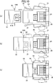
- FIG. 3 is an exploded perspective view of the cable connector 10 of FIG.
- the exploded perspective view of FIG. 3 is not complete, and a part of the shell 30, that is, a main body shell 31 to be described later, is attached to the main body portion 21 of the housing 20.
- the cable connector 10 mainly includes an insulating housing 20, a contact 11 held by the housing 20 in a state where a part of the housing 20 is exposed, a conductive shell 30 covering the outer peripheral surface of the housing 20, Furthermore, the insulating hood 12 that covers the outer peripheral surface of the shell 30 is provided.
- a fitting portion 27 to be inserted into the fitting hole 77 of the board connector 70 is provided on the front side of the fitting side of the housing 20, and the fitting portion 27 further has a fitting hole of the board connector 70.
- a fitting recess 28 into which the fitting protrusion provided in 77 is inserted is provided.
- the fitting recesses 28 are arranged with one end of the contact 11 exposed, while the other end of the contact 11 is electrically connected to a corresponding portion of the cable 5.
- the housing 20 includes a main body portion 21 and a fitted portion 27 extending from the main body portion 21 to the fitting side with the board connector 70.
- the side sections of the main body portion 21 and the fitted portion 27 are both substantially rectangular.
- a space in which the cable is fixed is provided inside the main body portion 21. In this space, in order to align the cables, a cable fixing portion provided with a groove-like cable fixing portion 24A corresponding to the core wire of each cable is provided.
- a member 24 is installed.
- one corner portion forming the side surface of the fitted portion 27 is a flat surface 27A for preventing erroneous fitting.
- the diameter of the side outer peripheral surface 23D of the fitted portion 27 along the circumferential direction of the housing 20 (the arrow “ ⁇ ” direction in the drawing) is set to be slightly smaller than the diameter of the side outer peripheral surface 23C of the main body portion 21. .
- the portion to be fitted 27 is relatively positioned while securing a space for connecting the contact 11 and the cable in the main body portion 21. Therefore, the connector device can be reduced in size.
- the to-be-fitted part 27 of this embodiment it is set smaller than that 23C of the main-body part 21 in all the side part outer peripheral surfaces 23D, However, It is not necessary to make all the surfaces small.
- a step surface 25 is formed between the main body portion 21 and the fitted portion 27, for example, along the radial direction of the housing 20 (for example, the direction along “ ⁇ ” or the like).
- the step surface 25 is not necessarily provided along the radial direction. For example, as it goes from the fitting side with the board connector 70 to the side opposite to the fitting side, from the small diameter side toward the large diameter side. It may be inclined.
- the shell 30 includes a main body shell 31, a plate-like shell 32, and a cylindrical shell 33.
- the plate-like shell 32 is not necessarily required and can be omitted. However, by providing these, it is possible to cover substantially the entire outer peripheral surface of the exposed surface of the housing 20 except the front side 23A and the back side 23B.
- the main body shell 31 mainly covers the outer peripheral surface of the main body portion 21 of the housing 20, in particular, the side outer peripheral surface 23C.
- the plate-like shell 32 mainly covers the outer peripheral surface of the main body portion 21 that is not covered by the main body shell 31.
- the cylindrical shell 33 mainly covers the outer peripheral surface of the fitted portion 27 of the housing 20, particularly the side outer peripheral surface 23D.
- the main body shell 31 is mainly attached to the housing 20, the plate-like shell 32 is mainly attached to the main body shell 31, and the cylindrical shell 33 is made up of the main body shell 21 and the plate-like shell 32. It is attached to both.
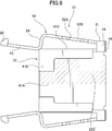
- FIG. 4 to 6 are perspective views of individual parts of the main body shell 31.
- FIG. 4 is a front perspective view of the main body shell 31
- FIG. 5 is a rear perspective view thereof
- FIG. 6 is a side view thereof.
- the main body shell 31 has a substantially C-shaped cross section as a whole.
- the main body shell 31 has at least one of an elastic arm 50 having a free end on the fitting side with the board connector 70 and a side outer peripheral surface 23C of the main body 21.
- Part for example, a vertical plate part 41A that covers one vertical surface of the housing 20, a vertical piece 41B that covers a part of the other vertical surface, and a horizontal plate part 41C that covers the upper and lower horizontal surfaces.
- the main body shell 31 is formed by punching a single metal plate and bending it. Therefore, all the above-mentioned parts included in the main body shell 31 are in a continuous state.
- the housing 20 is fixed by, for example, locking the mounting piece 45 provided on the horizontal plate portion 41 ⁇ / b> C at a predetermined position of the housing 20.
- the elastic arm 50 and the horizontal plate portion 41C are elastically connected through a support portion 44 formed as a folded portion having a substantially U shape in cross section, for example.
- the elastic arm 50 is supported in a cantilever shape with respect to the lateral plate portion 41C.
- the shape is not limited to the U-shape, and for example, the support portion 44 may have a substantially U-shape in cross-sectional view, a substantially V-shape, or a substantially continuous V-shape.
- a cutout 42 is provided at the front edge of the horizontal plate portion 41 ⁇ / b> C in order to avoid collision with the elastic arm 50.
- the position where the support portion 44 is provided in the elastic arm 50 may be, for example, on the side of the elastic arm 50 or on the rear side (the side opposite to the side on which the board connector 70 is fitted).
- the elastic arm 50 when connected on the side, the elastic arm 50 can be supported on the side closer to the free end (55) of the elastic arm 50 than when connected behind the elastic arm 50, and as a result, The elastic force of the elastic arm 50 can be increased.
- the length of the support portion 44 on the side in other words, the length of the portion substantially along the longitudinal direction of the elastic arm 50 can be adjusted easily and The elastic force can be adjusted relatively freely.
- the elastic force can be weakened, and if it is set long, the elastic force can be strengthened.
- the length on the connection side with the elastic arm 50 and the length on the connection side with the horizontal plate portion 41C may be set to the same length, or the lengths thereof may be set. You may make them different.
- the elastic force may be weakened by punching a hole in the support portion 44. In this case, since the support part 44 has a width
- the flat metal plate before the elastic arm 50 is bent and processed is behind the support portion 44 between the horizontal plate portion 41 ⁇ / b> C and the elastic arm 50.
- a long plate material for the elastic arm is required.
- the cable is used in a state in which the plate material which is not necessary for creating the elastic arm is connected to the horizontal plate portion 41C without using the cutting surface 46 at the rear side, for example.
- a gripping portion for gripping can be provided, and a shell material covering the rear end portion of the housing can be formed using such a plate material.
- the elastic arm 50 is supported in a state of having elasticity so that it can be displaced substantially in the radial direction with respect to the lateral plate portion 41C around the support portion 44.
- the reason “substantially in the radial direction” is that since the elastic arm 50 is connected to the support portion 44 on the side thereof, the elastic force is considered to work in a slightly deviated direction.
- the inclination is further increased. Further, the elastic arm 50 is held through the support portion 44 in a state of being separated from the horizontal plate portion 41C in the radial direction.
- the elastic arm 50 and the horizontal plate portion 41C have surfaces that are substantially opposed to each other, whereby a part of the housing can be covered with a double plate surface, thereby increasing the shielding effect. be able to.
- the reason “substantially opposed” is the same as above. That is, since the elastic arm 50 is connected to the support portion 44 on the side thereof, the elastic arm 50 is not opposed to face the front. In order to obtain the effect of the present configuration, it is sufficient that the elastic arm 50 and the horizontal plate portion 41C have overlapping surfaces.
- the elastic arm 50 extends from the main body portion 21 of the housing 20 to the fitted portion 27.
- the elastic arm includes a relatively wide support portion side portion 52 extending from the base portion 51 extending laterally in a continuous state from the support portion 44 to the board connector 70 side, and a relatively narrow free end portion portion 53.
- the former wide portion 52 is mainly located on the main body 21 side of the housing 20, and the latter narrow portion 53 is mainly located on the fitted portion 27 side of the housing 20.
- a stepped portion 54 is formed in the narrow portion 53 corresponding to the stepped surface 25 formed between the main body portion 21 and the fitted portion 27.
- the step portion 54 is substantially along the step surface 25. As described as “substantially along”, it is not required to be strictly “along”, and it is only necessary to be “along” while satisfying the conditions required in the embodiment. For example, if the step surface 25 is inclined, it may be inclined in accordance with this, or it is preferable that it is inclined.
- the narrow portion 53 is provided with a lock portion that locks the fitting when the cable connector 10 and the board connector 70 are fitted, for example, a lock projection 55 of the elastic arm 50 rather than the support portion 44. It is provided in a state of being erected substantially vertically at a position close to the free end side.
- At least a part of the free end side of the elastic arm 50 having the lock portion 55 is provided at a position closer to the fitted portion 27 side than the support portion 44 in the radial direction (“ ⁇ ” or the like)
- the device is easy to miniaturize.
- the lock protrusion 55 can move in the “ ⁇ ” direction by utilizing the elastic action of the support portion 44.
- the wide portion 52 is provided with a pushing member for unlocking operation, for example, a hole 52 A and a notch 52 B for attaching the button 13.
- the button 13 is positioned between the support portion 44 and the step portion 54 using the notch 52B, and the button 13 is attached to the hole 52A. By fitting the part 15, the button 13 can be fixed at a predetermined position of the elastic arm 50.
- the plate-like shell 32 is formed by punching a single metal plate and bending it in the same manner as the main body shell 31.
- the plate-like shell 32 includes, for example, a vertical plate portion 32A and horizontal plate portions 32B provided on the upper and lower sides, respectively, and has a substantially U-shaped cross section as a whole.
- the horizontal plate portion 32 ⁇ / b> B is mainly used for fixing the plate-like shell 32 to the main body shell 31.
- the horizontal plate portion 41C of the main body shell 31 is attached so as to be sandwiched from above and below, and as a result, the plate-like shell 32 and the main body shell 31 are overlapped in these horizontal plate portions.
- the tongue-like attachment piece 57 provided on the plate-like shell 32 is locked to the edge 43 ⁇ / b> A of the attachment hole 43 provided on the main body shell 31.
- the shell 32 is fixed to the main body shell 31.
- the escape hole 56 is provided in the vicinity of the center of the horizontal plate portion 32B of the plate-like shell 32. There is no hindrance. Further, the edge 32B ′ of the horizontal plate portion 32B of the plate-like shell 32 is formed in a state of being slightly retracted to the center side from the vertical plate portion 32A in order to prevent collision with the elastic arm 50 provided on the main body shell 31. ing.
- the vertical plate portion 32 ⁇ / b> A is not covered by the main body shell 31, for example, among the outer peripheral surfaces of the main body portion 21, in particular, the side outer peripheral surface 23 ⁇ / b> C, especially, along the fitting direction “ ⁇ ” with the board connector 70.
- the side outer peripheral surface 23 ⁇ / b> C located on the support portion 44 side with respect to the substantial center line “a” of the elastic arm 50 is covered.
- the vertical plate portion 32A of the plate-like shell 32 for example, at least a part of the outer peripheral surface of the side portion that can be covered for the first time by the main body shell 31 by folding the support portion 44, for example, the region of the shaded portion 23C ′ in FIG. It can be covered, and thereby the shielding effect can be enhanced.
- FIG. 9 shows a rear perspective view of the cylindrical shell 33.
- the cylindrical shell 33 is formed by punching a single metal plate and bending it, like the main shell 31 and the plate shell 32.
- the cylindrical shell 33 includes, for example, opposite left and right vertical plate portions 33A and 33A 'and opposite upper and lower horizontal plate portions 33B and 33B', and is formed as a substantially rectangular cylindrical body as a whole.
- the cylindrical shell 33 can be attached by inserting the fitted portion 27 of the housing 20 into the cylinder.
- a hole 61A is provided in an attachment piece 61 extending to the main body shell 31 side.
- the locking protrusion 22 protruding from the outer surface of the housing 20 is fitted into the hole 61 ⁇ / b> A.
- the vertical plate portion 33A ' is provided with a locking portion 62A on a mounting piece 62 extending toward the main body shell 31 side.
- the vertical plate portion 33A has a vertical plate portion 33A having a surface 61B that expands to the mounting side to the fitted portion 27 by slightly shifting the position where the mounting piece 61 is provided outward in the radial direction (“ ⁇ ” or the like).
- the surface 62B that expands toward the attachment side to the fitted portion 27 by further shifting the position where the attachment piece 62 is provided outward in the radial direction (“ ⁇ ” or the like) is further formed on the horizontal plate portion 33B.
- a surface 64A that extends to the attachment side to the fitted portion 27 is provided.
- the standing piece 64 is not necessarily provided along the radial direction, and is fitted from the fitting side with the board connector 70 in accordance with the step surface 25 or irrespective of the step surface 25, for example. You may incline toward the large diameter side from the small diameter side as it goes to the opposite side to the side.
- these surfaces 61B, 62B, 64A are brought into contact with the step surface 25 of the housing 20, the edge 41C1 of the main body shell 31, and both of them. Can do.
- the surface 64 ⁇ / b> A of the standing piece 64 can come into contact with the step surface 25 of the housing 20 or the horizontal plate portion 41 ⁇ / b> C of the main body shell 31. By providing these contact portions, the cylindrical shell 33 can be stably positioned at predetermined positions of the housing 20 and the main body shell 31.
- the lock projection 55 provided at the free end of the elastic arm 50 has its take-out hole 63 provided in the horizontal plate portion 33B of the cylindrical shell 44 due to its own elasticity. It is in a state of protruding from.
- at least a part of the free end side of the elastic arm 50, particularly, the free end side of the narrow portion 53 of the elastic arm 50 is disposed between the cylindrical shell 33 and the housing 20.
- at least a part of the free end side of the elastic arm 50 is protected by the cylindrical shell, which prevents the elastic arm 50 from buckling and makes the cable connector 10 and the board connector 70 smoother. Can be fitted.
- the recessed part 29 which escapes the elastic arm 50 in the to-be-fitted part 27 of the housing 20.
- the recess 29 for accommodating the elastic arm 50, the gap between the cylindrical shell 33 and the housing 20 can be further reduced.
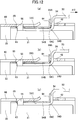
- FIG. 10 shows a side view of the housing 20, the main body shell 31 attached to the housing 20, and the cylindrical shell 33 to be assembled thereto.
- the plate-like shell 32 is omitted.
- the free end side of the elastic arm 50 is directed outward, in other words, from the center side of the housing 20 in order to increase the elastic force of the elastic arm. It is always biased toward the attachment side of the cylindrical shell 33. For this reason, in order to arrange the elastic arm 50 between the cylindrical shell 33 and the housing 20, the free end side of the elastic arm 50 is displaced toward the center side of the housing 20 by using the button 13 or the like, and FIG. It is necessary to change from the state shown in FIG. 10A to the state shown in FIG. After such a state, the cylindrical shell 33 is slid toward the fitted portion 27.
- the standing piece 64 provided in the cylindrical shell 33 for example, extending in the radial direction can be used as a guide portion of the elastic arm 50, in particular, the lock projection 55 provided at the tip thereof.
- the lock projection 55 of the elastic arm 50 protrudes elastically from the extraction hole 63 of the cylindrical shell 33.
- the surface 61B provided on the vertical plate portion 33A, the surface 62B provided on the vertical plate portion 33A ′ (see FIG. 3 and the like), and the surface 64A provided on the horizontal plate portion 33B are respectively steps of the housing 20.
- the surface 25 (see FIG. 3 and the like) or the edge 41C1 of the main body shell 31 may be abutted.
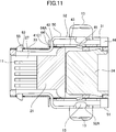
- FIG. 11 is a schematic centerline cross-sectional view of the cable connector 10
- FIG. 12 is an enlarged view of the periphery of the upright piece 64 in the cable connector 11 of FIG. Schematic concisely showing how the elastic arm 50 deforms when the cable connector 10 is forcibly separated from the board connector 70 after the cable connector 10 and the board connector 70 are fitted.
- the standing piece 64 is, for example, substantially in the radial direction (“ ⁇ ” in a state of facing the stepped portion 54 at a position closer to the fitting side with the board connector 70 than the stepped portion 54 of the elastic arm 50. Etc.).
- the standing piece 64 is not necessarily provided along the radial direction, and is fitted from the fitting side with the board connector 70, for example, in accordance with the elastic arm 50 or irrespective of the elastic arm 50. You may incline toward the large diameter side from the small diameter side as it goes to the opposite side to the side. Furthermore, the standing piece 64 only needs to face the step portion 54, and does not need to be strictly along the step portion 54. However, in order to obtain the effect of the standing piece 64, it is preferable to “substantially follow” the stepped portion 54.
- the free end side of the elastic arm 50 is always directed from the center side of the housing 20 toward the attachment side of the cylindrical shell 33 in order to increase the elastic force of the elastic arm. It is energized.
- the side where the lock projection 55 is provided is slightly more cylindrical than the side where the stepped portion 54 is provided. 11
- the outer surface 54B of the elastic arm 50 and the outer surface 54B of the elastic arm 50 are arranged on the side where the stepped portion 54 of the elastic arm 50 is provided, as shown in FIG.
- a gap 59 larger than the side on which the lock projection 55 is provided is formed between the inner surface 33C of the horizontal plate portion 33B of the cylindrical shell 33.
- the outer surface 54D near the curved portion of the step portion 54 is changed to the standing piece 64, particularly the bent portion.
- a force that further prevents pulling acts.
- the standing piece 64 it is possible to increase the strength against inadvertent pulling through the collision between a part of the elastic arm 50 and at least a part of the elastic arm.
- the gap 59 is not necessarily required, and may be substantially free of the gap 59.
Landscapes
- Details Of Connecting Devices For Male And Female Coupling (AREA)
Abstract
コネクタが相手コネクタから無理やり引き離されようとしたときの引っ張り強度を高めることができるコネクタを提供する。 ハウジングは、本体部と、相手コネクタとの嵌合側に延びる被嵌合部を有する。被嵌合部の側部外周面の径は、本体部のそれよりも、少なくとも一部において小さい。導電性シェルは、第一シェルと第二シェルを有する。第一シェルは、ハウジングの外周面の少なくとも一部を覆う覆部と、相手コネクタとの嵌合側に自由端を有する弾性腕と、覆部と弾性腕とを弾性的に接続し、弾性腕を片持ち梁状に支持する支持部を含む。弾性腕は、相手コネクタの嵌合をロックするロック部を有し、また、径の差を利用して設けられたハウジングの段面に対応して段部を有する。第二シェルは、弾性腕の段部よりも相手コネクタとの嵌合側に寄った位置に、段部と対峙した部分を有する。
Description
本発明は、シェルを有するコネクタ及びコネクタ装置に関する。
特開2002-367732(特許文献1)に、シェルを利用したロック機構を有するコネクタの一例が示されている。この種のコネクタは、携帯電話、PDA、パソコン等の電子機器のインタフェースとして利用されている。これらの電子機器では、信号の高速化が日々進んでおり、シェルを設けることによって、特性インピーダンスを調整し、さらには、外部からの電磁波ノイズに対するシールド効果を得ることができるようになっている。特許文献1では、更に、シェルにロック機構を設けることによって、不用意に嵌合が解除されてしまうことを防止することができるようになっている。
特許文献1に開示されたコネクタ100の分解組立斜視図を図13に示す。但し、ここでは外側のフードは省略されている。コネクタ100は、主に、インシュレータ103と、該インシュレータ103を覆うベースシェル101及びカバーシェル102から成る。ベースシェル101は、一枚の金属板から構成されており、天井板となる平板111、平板111の側方に直角に折り曲げられた側片112、更に側片112と連結されて片持ち梁状に支持されたアーム113を含む。アーム113の先端付近には係合片113aが設けられており、この部分が、相手コネクタ(図示されていない)との嵌合時に、相手コネクタの所定部分に係合して相手コネクタとの嵌合をロックする部分として機能する。
しかしながら、この特許文献1の構成では、コネクタと相手コネクタが嵌合された後に、コネクタが相手コネクタから無理やり引き離されたときに、弾性腕が容易に変形し、結果として、コネクタが破壊されてしまうという問題があった。
本発明は、このような従来技術における問題点を解決するためになされたものであり、コネクタと相手コネクタが嵌合された後に、コネクタが相手コネクタから無理やり引き離されようとしたときの引っ張り強度を高めることができるコネクタを提供することを目的とする。
上記の課題を解決するため、本発明の一態様によるコネクタは、相手コネクタと嵌合可能なコネクタであって、ハウジングと、該ハウジングに取り付けられるコンタクトと、該ハウジングに取り付けられる導電性のシェルとを備え、前記ハウジングは、本体部と、該本体部から前記相手コネクタとの嵌合側に延びる被嵌合部とを有し、該被嵌合部の側部外周面の径は、前記本体部の側部外周面の径より、少なくとも一部において小さく設定されており、前記導電性シェルは、第一シェルと第二シェルを有し、前記第一シェルは、前記ハウジングの外周面の少なくとも一部を覆う覆部と、前記相手コネクタとの嵌合側に自由端を有する弾性腕と、前記覆部と前記弾性腕とを弾性的に接続し、前記弾性腕を片持ち梁状に支持する支持部とを含み、前記弾性腕は、前記支持部よりも前記自由端側に寄った位置に前記コネクタと前記相手コネクタの嵌合をロックするロック部を有し、前記弾性腕は、前記本体部と前記被嵌合部との間に前記径の差を利用して設けられた前記ハウジングの段面に対応して段部を有し、前記第二シェルは、前記弾性腕の段部よりも前記相手コネクタとの嵌合側に寄った位置に、前記段部と対峙した部分を有することを特徴とする。
この態様のコネクタによれば、第二シェルの少なくとも一部に、段部と対峙した部分を設けることにより、コネクタと相手コネクタが嵌合された後に、コネクタが相手コネクタから無理やり引き離されたときに、弾性腕の変形に伴って弾性腕の一部と、第二シェルの少なくとも一部とが衝突することになり、このような衝突を通じて引っ張り強度を高めることができる。また、この態様のコネクタによれば、被嵌合部の径を本体部の径より小さくすることによって、コネクタを小型化できる。更に、この態様のコネクタによれば、第一シェルに加えて第二シェルを設けたことにより、ハウジングの本体部における遮蔽効果を高めることができる。
この態様のコネクタによれば、第二シェルの少なくとも一部に、段部と対峙した部分を設けることにより、コネクタと相手コネクタが嵌合された後に、コネクタが相手コネクタから無理やり引き離されたときに、弾性腕の変形に伴って弾性腕の一部と、第二シェルの少なくとも一部とが衝突することになり、このような衝突を通じて引っ張り強度を高めることができる。また、この態様のコネクタによれば、被嵌合部の径を本体部の径より小さくすることによって、コネクタを小型化できる。更に、この態様のコネクタによれば、第一シェルに加えて第二シェルを設けたことにより、ハウジングの本体部における遮蔽効果を高めることができる。
上記態様のコネクタにおいて、前記弾性腕の自由端側の少なくとも一部は、前記径方向において前記支持部よりも前記被嵌合部の側に寄った位置に設けられていてもよい。これによりコネクタを小型化することができる。
また、上記態様のコネクタにおいて、前記ロック部を有する前記弾性腕の自由端側の少なくとも一部は、前記第二シェルと前記ハウジングの間に配置されていてもよい。これにより、弾性腕の自由端側の少なくとも一部を第二シェルによって保護して、弾性腕の座屈を防ぐとともに、コネクタと相手コネクタをよりスムースに嵌合させることができる。
更に、上記態様のコネクタにおいて、前記ハウジングの被嵌合部に、前記弾性腕の自由端側の少なくとも一部を逃がす窪みが設けられているのが好ましい。弾性腕を逃がす空間を被嵌合部に設けることにより、第二シェルとハウジングの間の隙間をより小さくすることができる。
また、上記態様のコネクタにおいて、少なくとも、前記第二シェルと前記ハウジングの間に配置された前記弾性腕の自由端側の少なくとも一部は、前記ハウジングの側から前記第二シェルの側に向かって常時付勢されているのが好ましい。弾性腕を付勢することにより、弾性腕を利用した固定力を高めることができる。
また、上記態様のコネクタにおいて、前記第二シェルは、前記径方向に拡がる面を有し、当該面において、前記ハウジングの段面、及び/又は、前記金属シェルと当接し得るようになっていてもよい。当接部を設けることにより、第二シェル)を位置決めすることが容易となる。
また、上記態様のコネクタにおいて、前記覆部と前記弾性腕は、互いに実質的に対向する面を有するのが好ましい。この態様によれば、弾性腕と覆部とを、それらの面で突き合わせることにより、ハウジングの一部を二重の板面で覆うことができ、これによって遮蔽効果を増大させることができる。
更に、上記態様のコネクタにおいて、前記導電性シェルは、更に、前記第一シェルによって覆われていない前記本体部の外周面の少なくとも一部を覆う第三シェルを有するのが好ましい。第三シェルを設けることにより、遮蔽効果を高めることができる。
上記態様のコネクタにおいて、前記第一シェルは、一枚の金属板から成っていてもよい。
また、上記態様のコネクタにおいて、前記コネクタと前記相手コネクタを組としてコネクタ装置としてもよい。
また、上記態様のコネクタにおいて、前記コネクタと前記相手コネクタを組としてコネクタ装置としてもよい。
本発明によれば、コネクタと相手コネクタが嵌合された後に、コネクタが相手コネクタから無理やり引き離されようとしたときの引っ張り強度を高めることができる。
以下、図面を参照して、本発明の一つの好適な実施形態によるコネクタ及びコネクタ装置について説明する。
図1に、本発明の一つの好適な実施形態によるコネクタ装置1の斜視図を示す。このコネクタ装置1は、互いに嵌合可能なコネクタ10と相手コネクタ70の組から成る。コネクタ10は、例えば、電気ケーブル5に接続されたケーブルコネクタ、一方、相手コネクタ70は、例えば、基板3に接続された基板コネクタであってもよい。ここでは好適な一つの例として電気ケーブルコネクタを例に挙げて説明するが、勿論、本発明を電気ケーブルコネクタに限定する意図ではない。本発明の構成を採用することができるコネクタ構造を有していれば、本発明は様々なコネクタ装置に適用することができる。例えば、本構成を光コネクタに適用することもできるし、また、コネクタ10を基板コネクタとし相手コネクタ70をケーブルコネクタとしてもよい。また、コネクタ10と相手コネクタ70の双方を基板コネクタとしてもよいし、或いは、双方をケーブルコネクタとしてもよい。
図1に、本発明の一つの好適な実施形態によるコネクタ装置1の斜視図を示す。このコネクタ装置1は、互いに嵌合可能なコネクタ10と相手コネクタ70の組から成る。コネクタ10は、例えば、電気ケーブル5に接続されたケーブルコネクタ、一方、相手コネクタ70は、例えば、基板3に接続された基板コネクタであってもよい。ここでは好適な一つの例として電気ケーブルコネクタを例に挙げて説明するが、勿論、本発明を電気ケーブルコネクタに限定する意図ではない。本発明の構成を採用することができるコネクタ構造を有していれば、本発明は様々なコネクタ装置に適用することができる。例えば、本構成を光コネクタに適用することもできるし、また、コネクタ10を基板コネクタとし相手コネクタ70をケーブルコネクタとしてもよい。また、コネクタ10と相手コネクタ70の双方を基板コネクタとしてもよいし、或いは、双方をケーブルコネクタとしてもよい。
ケーブルコネクタ10と基板コネクタ70は、図示矢印「α」方向に沿って、互いに接近させ、或いは、引き離すことにより、自由に着脱させることができる。また、シェルを利用して、ケーブルコネクタ10と基板コネクタ70との間の嵌合をロックすることができる。ケーブルコネクタ10と基板コネクタ70を嵌合させたとき、基板コネクタ70の前面に設けた略矩形の嵌合穴77に、ケーブルコネクタ10のシェル30に設けた先細の被嵌合部が挿入されるとともに、基板コネクタ70のシェル80の天井部及び底板部に設けた被ロック部、例えば、貫通孔85に、ケーブルコネクタ10の先端部分30の上部及び下部から弾性的に突出したロック部、例えば、ロック突部55が、例えば上部側では図示矢印「β1」方向に自身の弾性によって移動して貫通孔85に嵌る。この結果、ケーブルコネクタ10と基板コネクタ70の嵌合はロックされる。このロックは、ケーブルコネクタ10に設けたボタン13を、例えば、上部側では、「β1」とは逆方向の図示矢印「β2」方向に押すことにより弾性腕50を変位させ、貫通孔85からロック突部55を移動させて取り除くことによって簡単に解除することができる。尚、基板コネクタのロック部は、ケーブルコネクタ10の所定部分をロックできれば足り、従って、貫通孔85に限らず、例えば、窪み等であってもよい。
基板コネクタ70は、主に、絶縁性のハウジング72と、ハウジング72から一部を露出させた状態でハウジング72に保持されたコンタクト71と、更に、ハウジング72の外周面を覆う導電性のシェル80を有する。
ハウジング72の前面には、コネクタ10の一部を嵌合させる嵌合穴77が設けられており、嵌合穴77には、更に、コネクタ10の嵌合口の形状に適合する嵌合凸部(図示されていない)が設けられている。嵌合凸部には、コンタクト71の一端側が露出した状態で配列され、一方、コンタクト71の他端側71Aは、基板3に半田付けされている。
シェル80は、嵌合穴77を除くハウジング72の露出面の略全ての外周面を覆う。特に嵌合穴77の左右側縁では、折返部82を設けて強度を確保している。折返部82の下端部81Aは、基板3の貫通穴3Aに貫通させ、シェル80の位置決め及び基板への固定に利用されている。基板の所定位置に固定されることにより、シェルはグランドに落とされる。同様に、嵌合穴77から離れた側でも、シェル80の下端部81Bが、基板3への固定等のために利用されている。
図2は、図1からフード12を取り除いたケーブルコネクタ10の斜視図、図3は、図2のケーブルコネクタ10の分解斜視図である。但し、図3の分解斜視図は完全なものではなく、シェル30の一部、即ち、後述する本体シェル31はハウジング20の本体部21に取り付けた状態とされている。
ケーブルコネクタ10は、主に、絶縁性のハウジング20と、ハウジング20から一部を露出させた状態でハウジング20に保持されたコンタクト11と、ハウジング20の外周面を覆う導電性のシェル30と、更に、シェル30の外周面を覆う絶縁性のフード12を有する。
ハウジング20の嵌合側前面には、基板コネクタ70の嵌合穴77に挿入される被嵌合部27が設けられており、被嵌合部27には、更に、基板コネクタ70の嵌合穴77に設けた嵌合凸部が挿入される嵌合凹部28が設けられている。嵌合凹部28には、コンタクト11の一端側が露出した状態で配列され、一方、コンタクト11の他端側は、ケーブル5の対応部分と電気的に接続されている。
ハウジング20は、本体部21と、この本体部21から基板コネクタ70との嵌合側に延びる被嵌合部27を含む。本体部21と被嵌合部27の側方断面は、共に略矩形である。本体部21の内部には、ケーブルが固定される空間が設けられており、この空間には、ケーブルを整列させるため、各ケーブルの芯線に対応する溝状のケーブル固定部24Aを設けたケーブル固定部材24が設置されている。また、被嵌合部27の側面を形成している一つの角部は、誤嵌合防止のため、平面27Aとされている。
ハウジング20の周方向(図示矢印「γ」方向)に沿う、被嵌合部27の側部外周面23Dの径は、本体部21の側部外周面23Cの径より一回り小さく設定されている。このように、被嵌合部27を本体部21より小径とすることにより、本体部21におけるコンタクト11とケーブルとの接続作業のための空間を確保しつつ、被嵌合部27部分を相対的に小さくできるので、コネクタ装置の小型化が図られる。尚、本実施形態の被嵌合部27では、その全ての側部外周面23Dにおいて、本体部21のそれ23Cより小さく設定されているが、必ずしも全ての面を小さくする必要はない。被嵌合部27の側部外周面23Dのうちの少なくとも一部、例えば、図3の上下方向(図示矢印「β」方向)において向かい合う面だけを、或いは、この上下方向に対して直交する左右方向において向かい合う面だけを、本体部21の側部外周面23Cより小さく設定してもよい。この径の差を利用して、本体部21と被嵌合部27との間に、例えば、ハウジング20の径方向(例えば「β」等に沿う方向)に沿って、段面25が形成される。但し、段面25は、必ずしも、径方向に沿って設けられる必要はなく、例えば、基板コネクタ70との嵌合側から嵌合側とは反対側に向かうにつれて小径側から大径側に向かって傾斜していてもよい。
シェル30は、本体シェル31、板状シェル32、及び筒状シェル33を含む。板状シェル32は必ずしも必要なものではなく、省略することもできる。但し、これらを設けることにより、前面側23Aと背面側23Bを除くハウジング20の露出面の略全ての外周面を覆うことができる。本体シェル31は、主に、ハウジング20の本体部21の外周面、特に、側部外周面23Cを覆う。板状シェル32は、主に、本体シェル31によって覆われていない本体部21の外周面を覆う。筒状シェル33は、主に、ハウジング20の被嵌合部27の外周面、特に、側部外周面23Dを覆う。また、本体シェル31は、主に、ハウジング20に対して取り付けられ、板状シェル32は、主に、本体シェル31に対して取り付けられ、筒状シェル33は、本体シェル21と板状シェル32の双方に対して取り付けられる。
図4乃至図6に、本体シェル31の個品図を斜視図で示す。図4は、本体シェル31の前側斜視図、図5は、その後側斜視図、図6は、その側面図である。本体シェル31は、全体として略Cの字状の断面を有し、例えば、基板コネクタ70との嵌合側に自由端を有する弾性腕50と、本体部21の側部外周面23Cの少なくとも一部、例えば、ハウジング20の一方の縦面を覆う縦板部41A、他方の縦面の一部を覆う縦片41B、更に、上下の横面を覆う横板部41Cを含む。本体シェル31は、一枚の金属板を打ち抜き、折り曲げ加工することによって成っている。従って、本体シェル31に含まれる上記の部分は全て互いに連続した状態にある。ハウジング20に対する固定は、例えば、横板部41Cに設けた取付片45をハウジング20の所定位置に係止されることにより成される。
弾性腕50と横板部41Cは、例えば、断面視略U字状の折り返し部として形成された支持部44を介して弾性接続されている。支持部44を介して接続されることにより、弾性腕50は、横板部41Cに対して片持ち梁状に支持される。勿論、U字状に限らず、例えば、断面視略コの字状、略V字、略V字を複数連続させた形状の支持部44等としてもよい。横板部41Cの前縁には、弾性腕50との衝突を避けるため、切り欠き42が設けられている。
弾性腕50において支持部44を設ける位置は、例えば、弾性腕50の側方であってもよいし、後方(基板コネクタ70との嵌合側とは反対側))であってもよい。但し、側方にて接続した場合には、弾性腕50の後方で接続した場合に比べ、弾性腕50の自由端(55)により近い側で弾性腕50を支持することができ、この結果、弾性腕50の弾性力を高めることができる。また、側方で接続した場合には、支持部44の側方における長さ、換言すれば、弾性腕50の長手方向に実質的に沿った部分の長さを調整することによって、容易に且つ比較的自由に、弾性力を調整することができる。例えば、支持部44の側方における長さを短く設定すれば、弾性力を弱めることができるし、長く設定すれば、弾性力を強めることができる。この場合、例えば、図示実施形態のように、弾性腕50との接続側における長さと横板部41Cとの接続側における長さを同じ長さに設定してもよいし、それらの長さを異ならしめてもよい。また、支持部44にパンチで穴を空ける等して弾性力を弱めてもよい。この場合、支持部44は、それを後方に設けた場合に比べて大きな幅を有しているため、比較的容易にそのような穴を設けることができる。更に、弾性腕50の後方で接続する場合には、弾性腕50を折り曲げ等して加工する前の平らな金属板において、横板部41Cと弾性腕50との間の支持部44よりも後方に、弾性腕のための長い板材料が必要とされてしまうが、側方にて接続させることにより、そのような板材料が不要となるため、資源の有効活用を図ることができる。更に、この場合には、弾性腕を作成するために不要となる板材料を利用して、例えば、横板部41Cの後方を切断面46とすることなく、これと連結させた状態でケーブルを把持する把持部を設けることもできるし、また、このような板材料を利用して、ハウジングの後端部を覆うシェル材料を形成することもできる。
弾性腕50は、支持部44を中心として、横板部41Cに対して実質的に径方向に変位可能に弾性を有した状態で支持される。「実質的に径方向」としたのは、弾性腕50は、その側方において支持部44に接続されているため、弾性力は多少偏った方向に働くと考えられるためである。V字状の支持部44を用いた場合には、傾きは更に大きくなる。また、支持部44を通じて、弾性腕50は、横板部41Cと互いに径方向において離間された状態で保持される。この場合、弾性腕50と横板部41Cは、互いに実質的に対向する面を有することになり、これにより、ハウジングの一部を二重の板面で覆うことができ、遮蔽効果を増大させることができる。「実質的に対向」としたのは、上記と同様の理由による。つまり、弾性腕50は、その側方において支持部44に接続されているため、真正面を向いた状態で対向するわけではないからである。本構成の効果を得るには、弾性腕50と横板部41Cは、面において重なりを有すれば足りる。
弾性腕50は、ハウジング20の本体部21から被嵌合部27に亘って延在する。弾性腕は、支持部44から連続した状態で側方に延びる基部51から基板コネクタ70側に延びる比較的幅広の支持部側の部分52と、比較的幅狭の自由端側の部分53を含み、前者の幅広部分52は、主に、ハウジング20の本体部21の側に位置し、後者の幅狭部分53は、主に、ハウジング20の被嵌合部27の側に位置する。
幅狭部分53には、本体部21と被嵌合部27との間に形成された段面25に対応して段部54が形成されている。段部54は、段面25に実質的に沿っている。「実質的に沿って」と記載しているように、厳密に「沿って」いることまで要求されるわけではなく、実施形態で要求される条件を満たす状態で「沿って」いればよい。例えば、段面25が傾斜していれば、これに合わせて傾斜していてもよいし、傾斜しているのが好ましい。また、この幅狭部分53には、ケーブルコネクタ10と基板コネクタ70が嵌合されたときにこの嵌合をロックするロック部、例えば、ロック突部55が、支持部44よりも弾性腕50の自由端側に寄った位置に略垂直に立設した状態で設けられている。このロック部55を有する弾性腕50の自由端側の少なくとも一部は、径方向(「β」等)において支持部44よりも被嵌合部27の側に寄った位置に設けられており、装置を小型化しやすい構成となっている。ロック突部55は、支持部44における弾性作用を利用して、「β」方向に移動し得る。弾性腕50の押操作、即ち、「β2」方向への操作を容易にするため、幅広部分52には、ロック解除操作用の押部材、例えば、ボタン13を取り付けるための穴52A及び切欠52Bが設けられている。図4、図6にそれぞれ対応する図7、図8に示すように、切欠52Bを利用して支持部44と段部54の間にボタン13を位置決めし、また、穴52Aにボタン13の取付部15を嵌めることにより、ボタン13を弾性腕50の所定位置に固定することができる。
板状シェル32は、本体シェル31と同様に、一枚の金属板を打ち抜き、折り曲げ加工することによって成る。板状シェル32は、例えば、縦板部32Aと、上下それぞれに設けた横板部32Bとから成り、全体として略コの字状の断面を有する。
横板部32Bは、主に、板状シェル32を本体シェル31へ固定するために使用される。本体シェル31の横板部41Cを上下方向から挟み込むようにして取り付けられ、この結果、これらの横板部において、板状シェル32と本体シェル31は重ねられた状態となる。板状シェル32を本体シェル31に取り付けたとき、板状シェル32に設けた舌状の取付片57が、本体シェル31に設けた取付穴43の縁43Aに係止され、これにより、板状シェル32は本体シェル31に固定された状態となる。尚、板状シェル32と本体シェル31が重ねられても、板状シェル32の横板部32Bの中心付近に逃げ穴56が設けられているため、本体シェル31に取り付けたボタン13の操作が妨げられることはない。また、板状シェル32の横板部32Bの縁32B’は、本体シェル31に設けた弾性腕50との衝突を防止するため、縦板部32Aよりも若干中心側に引っ込めた状態で形成されている。
縦板部32Aは、例えば、本体シェル31によって覆われていない、本体部21の外周面のうちの、特に、側部外周面23C、取り分け、基板コネクタ70との嵌合方向「α」に沿う弾性腕50の実質的な中心線「a」に対して支持部44の側に位置する側部外周面23Cを覆う。弾性腕50を設けた場合、本体シェル31の一部は弾性腕50のために使用されてしまうことから、本体シェル31によって覆うことができるハウジング20の面積は、弾性腕50を設けた分だけ減ることになる。板状シェル32の縦板部32Aによって、例えば、支持部44を折り返すことにより本体シェル31によって初めて覆うことができる側部外周面の少なくとも一部、例えば、図6の斜線部23C’の領域を覆うことができ、これにより、遮蔽効果を高めることができる。
図9に、筒状シェル33の後方斜視図を示す。筒状シェル33は、本体シェル31や板状シェル32と同様に、一枚の金属板を打ち抜き、折り曲げ加工することによって成る。筒状シェル33は、例えば、相対する左右の縦板部33A、33A’と、相対する上下の横板部33B、33B’を含み、全体として略矩形の筒状体として形成されている。勿論、必ずしも、筒状に形成する必要はないが、筒状とした場合には、ハウジング20の被嵌合部27の側部外周面の全体を簡単に覆うことができる。筒状シェル33は、ハウジング20の被嵌合部27を筒内に挿入するようにして取り付けることができる。
縦板部33Aには、筒状シェル33を本体シェル31に固定するため、本体シェル31側に延びた取付片61に穴61Aが設けられている。本体シェル31への固定時には、この穴61Aに、ハウジング20の外面に突出した係止突部22が嵌る。一方、縦板部33A’には、本体シェル31側に延びた取付片62に係止部62Aが設けられている。図面からは明らかでないが、本体シェル31への固定時には、これらの係止片62Aが本体シェル31の所定部分に係止される。
縦板部33Aには、取付片61を設ける位置を径方向(「β」等)において外方に多少ずらすことにより、被嵌合部27への取付側に拡がる面61Bが、縦板部33A’には、取付片62を設ける位置を径方向(「β」等)において外方に多少ずらすことにより、被嵌合部27への取付側に拡がる面62Bが、更に、横板部33Bには、例えば、径方向(「β」等)に沿って外方に延びた立片64を設けることによって、被嵌合部27への取付側に拡がる面64Aが、それぞれ設けられている。尚、立片64は、必ずしも、径方向に沿って設けられる必要はなく、段面25に合わせて、又は、段面25とは無関係に、例えば、基板コネクタ70との嵌合側から嵌合側とは反対側に向かうにつれて小径側から大径側に向かって傾斜していてもよい。筒状シェル33を被嵌合部27に取り付ける際、これらの面61B、62B、64Aを、ハウジング20の段面25、又は、本体シェル31の縁41C1、更に、それらの双方に当接させることができる。例えば、立片64の面64Aは、ハウジング20の段面25や本体シェル31の横板部41Cと当接し得る。これらの当接部を設けることにより、筒状シェル33を、ハウジング20や本体シェル31の所定位置に安定して位置決めすることができる。
筒状シェル33を被嵌合部27に取り付けたとき、弾性腕50の自由端に設けたロック突部55は、自身の弾性により、筒状シェル44の横板部33Bに設けた取出孔63から突出した状態とされる。また、このとき、弾性腕50の自由端側の少なくとも一部、特に、弾性腕50の幅狭部分53の自由端側は、筒状シェル33とハウジング20の間に配置される。この結果、弾性腕50の自由端側の少なくとも一部は、筒状シェルによって保護されることになり、これにより、弾性腕50の座屈を防ぐとともに、ケーブルコネクタ10と基板コネクタ70をよりスムースに嵌合させることができる。尚、ハウジング20の被嵌合部27には、弾性腕50を逃がす窪み29を設けるのが好ましい。弾性腕50を収容する窪み29を設けることにより、筒状シェル33とハウジング20の間の隙間をより小さくすることができる。
図10を参照して、ハウジング20の被嵌合部27に対する筒状シェル33の組付方法を説明する。図10は、ハウジング20と、これに取り付けた本体シェル31、及び、これらに組み付ける筒状シェル33の横面図を示している。尚、板状シェル32は省略している。
図10の(a)から明らかなように、弾性腕50の自由端側の少なくとも一部は、弾性腕の弾性力を高めるため、外方に向かって、換言すれば、ハウジング20の中心側から筒状シェル33の取り付け側に向かって常時付勢されている。このため、弾性腕50を筒状シェル33とハウジング20の間に配置するには、ボタン13等を利用して弾性腕50の特に自由端側をハウジング20の中心側に変位させ、図10の(a)示す状態から図10の(b)に示す状態とする必要がある。このような状態とした後に、筒状シェル33を被嵌合部27に向かってスライドさせる。この際、筒状シェル33に設けた、例えば径方向に延びる立片64を、弾性腕50、特に、その先端に設けたロック突部55の案内部として利用することができる。筒状シェル33がハウジング20に対して図10の(c)に示す位置に達したとき、弾性腕50のロック突部55は、筒状シェル33の取出孔63から弾性的に突出する。更に、このとき、縦板部33Aに設けた面61B、縦板部33A’に設けた面62B(図3等参照)、及び横板部33Bに設けた面64Aが、それぞれ、ハウジング20の段面25(図3等参照)又は本体シェル31の縁41C1と当接され得る。
図11、図12を参照して、筒状シェル33に設けた立片64による引張防止構造について説明する。図11は、ケーブルコネクタ10の概略中心線断面図、図12は、基板コネクタ70と嵌合状態にある、図11のケーブルコネクタ11における立片64の周辺を拡大して示した図であって、ケーブルコネクタ10と基板コネクタ70が嵌合された後に、ケーブルコネクタ10が基板コネクタ70から無理やり引き離されたときに、弾性腕50がどのように変形するのかを、段階的に簡潔に示した模式図である。ここで、立片64は、弾性腕50の段部54よりも基板コネクタ70との嵌合側に寄った位置に、段部54と対峙した状態で、例えば、実質的に径方向(「β」等)に延びている。尚、立片64は、必ずしも、径方向に沿って設けられる必要はなく、弾性腕50に合わせて、又は、弾性腕50とは無関係に、例えば、基板コネクタ70との嵌合側から嵌合側とは反対側に向かうにつれて小径側から大径側に向かって傾斜していてもよい。更に言えば、立片64は、段部54と対峙していれば足り、段部54に対して厳密に「沿って」いる必要はない。但し、立片64の効果を得るには、段部54に「実質的に沿って」いるのが好ましい。
図9を参照して説明したように、弾性腕50の自由端側の少なくとも一部は、弾性腕の弾性力を高めるため、ハウジング20の中心側から筒状シェル33の取り付け側に向かって常時付勢されている。しかしながら筒状シェル33とハウジング20の間に配置された弾性腕50の自由端側の少なくとも一部において、ロック突部55を設けた側は、段部54を設けた側よりも、若干、筒状シェル33の取り付け側に寄った位置に位置していることから、図11の(a)に示すように、弾性腕50の段部54を設けた側では、弾性腕50の外側表面54Bと、筒状シェル33の横板部33Bの内側表面33Cとの間に、ロック突部55を設けた側よりも大きな隙間59が形成される。ケーブルコネクタ10が基板コネクタ70から引き離される方向、即ち、「α2」方向に引っ張られたとき、弾性腕50が筒状シェル33の側に引き寄せられるように変形して隙間59が埋まり、図11の(b)に示すように、弾性腕50の外側表面54Bと、筒状シェル33の横板部33Bの内側表面33Cとが接触した状態になる。これにより、ケーブルコネクタ10が基板コネクタ70から引き離される力に対して抗力が生ずる。その後、更に、「α2」方向に引っ張られると、弾性腕50の特に段部54付近が変形し、この結果、段部54の曲部付近の外側表面54Dが、立片64、特に、その曲部付近の内側表面64Cと衝突することにより、引っ張りを更に阻止する力が働く。このように、立片64を設けることにより、弾性腕50の一部と弾性腕の少なくとも一部との衝突を通じて、不用意な引っ張りに対する強度を高めることができる。尚、隙間59は必ずしも必要なものではなく、隙間59を実質的に有しないものであってもよい。
尚、本発明は、上述した実施の形態に限定されるわけではなく、その他種々の変更が可能である。従って、ここに開示された実施形態は例示であって制限的なものではなく、本発明の範囲は上記した説明ではなく特許請求の範囲によって定められるべきであり、特許請求の範囲と均等の意味及び範囲内での全ての変更が含まれる。
1 コネクタ
3 基板
10 ケーブルコネクタ(コネクタ)
20 ハウジング
23C 側部外周面
23D 側部外周面
25 段面
21 本体部
27 被嵌合部
30 導電性シェル
31 本体シェル(第一シェル)
32 板状シェル(第三シェル)
33 筒状シェル(第二シェル)
33C 内側表面
44 支持部
50 弾性腕
54 段部
54B 外側表面
54D 外側表面
55 ロック部
59 隙間
64 立片
64C 内側表面
70 基板コネクタ(相手コネクタ)
71 コンタクト
72 ハウジング
80 導電性シェル
3 基板
10 ケーブルコネクタ(コネクタ)
20 ハウジング
23C 側部外周面
23D 側部外周面
25 段面
21 本体部
27 被嵌合部
30 導電性シェル
31 本体シェル(第一シェル)
32 板状シェル(第三シェル)
33 筒状シェル(第二シェル)
33C 内側表面
44 支持部
50 弾性腕
54 段部
54B 外側表面
54D 外側表面
55 ロック部
59 隙間
64 立片
64C 内側表面
70 基板コネクタ(相手コネクタ)
71 コンタクト
72 ハウジング
80 導電性シェル
Claims (10)
- 相手コネクタと嵌合可能なコネクタであって、
ハウジングと、該ハウジングに取り付けられるコンタクトと、該ハウジングに取り付けられる導電性のシェルとを備え、
前記ハウジングは、本体部と、該本体部から前記相手コネクタとの嵌合側に延びる被嵌合部とを有し、該被嵌合部の側部外周面の径は、前記本体部の側部外周面の径より、少なくとも一部において小さく設定されており、
前記導電性シェルは、第一シェルと第二シェルを有し、
前記第一シェルは、前記ハウジングの外周面の少なくとも一部を覆う覆部と、前記相手コネクタとの嵌合側に自由端を有する弾性腕と、前記覆部に前記弾性腕を弾性接続し、前記弾性腕を片持ち梁状に支持する支持部とを含み、前記弾性腕は、前記支持部よりも前記自由端側に寄った位置に前記コネクタと前記相手コネクタの嵌合をロックするロック部を有し、
前記弾性腕は、前記本体部と前記被嵌合部との間に前記径の差を利用して設けられた前記ハウジングの段面に対応して段部を有し、
前記第二シェルは、前記弾性腕の段部よりも前記相手コネクタとの嵌合側に寄った位置に、前記段部と対峙した部分を有することを特徴とするコネクタ。 - 前記弾性腕の自由端側の少なくとも一部は、前記径方向において前記支持部よりも前記被嵌合部の側に寄った位置に設けられている請求項1に記載のコネクタ。
- 前記ロック部を有する前記弾性腕の自由端側の少なくとも一部は、前記第二シェルと前記ハウジングの間に配置される請求項2に記載のコネクタ。
- 前記ハウジングの被嵌合部に、前記弾性腕の自由端側の少なくとも一部を逃がす窪み(29)が設けられている請求項3に記載のコネクタ。
- 少なくとも、前記第二シェルと前記ハウジングの間に配置された前記弾性腕の自由端側の少なくとも一部は、前記ハウジングの側から前記第二シェルの側に向かって常時付勢されている請求項3又は4に記載のコネクタ。
- 前記第二シェルは、前記径方向に拡がる面を有し、当該面において、前記ハウジングの段面、及び/又は、前記金属シェルと当接し得る請求項1乃至5のいずれかに記載のコネクタ。
- 前記覆部と前記弾性腕は、互いに実質的に対向する面を有する請求項1乃至6のいずれかに記載のコネクタ。
- 前記導電性シェルは、更に、前記第一シェルによって覆われていない前記本体部の外周面の少なくとも一部を覆う第三シェルを有する請求項1乃至7のいずれかに記載のコネクタ。
- 前記第一シェルは、一枚の金属板から成る請求項1乃至8のいずれかに記載のコネクタ。
- 請求項1乃至9のいずれかに記載の前記コネクタと前記相手コネクタとから成るコネクタ装置。
Priority Applications (3)
| Application Number | Priority Date | Filing Date | Title |
|---|---|---|---|
| CN201780007747.1A CN108475883B (zh) | 2016-02-26 | 2017-02-27 | 具有壳的连接器以及连接器装置 |
| EP17756693.2A EP3422489A4 (en) | 2016-02-26 | 2017-02-27 | CONNECTOR WITH COVER AND CONNECTING DEVICE |
| US16/075,881 US10461478B2 (en) | 2016-02-26 | 2017-02-27 | Connector having shell and connector device |
Applications Claiming Priority (2)
| Application Number | Priority Date | Filing Date | Title |
|---|---|---|---|
| JP2016035635A JP6818418B2 (ja) | 2016-02-26 | 2016-02-26 | シェルを有するコネクタ及びコネクタ装置 |
| JP2016-035635 | 2016-02-26 |
Publications (1)
| Publication Number | Publication Date |
|---|---|
| WO2017146259A1 true WO2017146259A1 (ja) | 2017-08-31 |
Family
ID=59685192
Family Applications (1)
| Application Number | Title | Priority Date | Filing Date |
|---|---|---|---|
| PCT/JP2017/007561 Ceased WO2017146259A1 (ja) | 2016-02-26 | 2017-02-27 | シェルを有するコネクタ及びコネクタ装置 |
Country Status (5)
| Country | Link |
|---|---|
| US (1) | US10461478B2 (ja) |
| EP (1) | EP3422489A4 (ja) |
| JP (1) | JP6818418B2 (ja) |
| CN (1) | CN108475883B (ja) |
| WO (1) | WO2017146259A1 (ja) |
Families Citing this family (17)
| Publication number | Priority date | Publication date | Assignee | Title |
|---|---|---|---|---|
| USD852142S1 (en) | 2015-12-03 | 2019-06-25 | Hirose Electric Co., Ltd. | Electrical connector |
| JP6761665B2 (ja) * | 2016-05-16 | 2020-09-30 | ヒロセ電機株式会社 | 信号端子とグランド端子を備えた電気コネクタ、及び、これを用いた電気コネクタ装置 |
| DE102016221063B4 (de) * | 2016-10-26 | 2021-09-16 | BSH Hausgeräte GmbH | Haushaltsgerät mit zumindest einem Stecker für eine elektrische Verbindung |
| JP1589651S (ja) * | 2017-03-13 | 2017-10-30 | ||
| DE102018201178B3 (de) * | 2018-01-25 | 2019-06-06 | Robert Bosch Gmbh | Elektrischer Steckverbinder |
| EP3528348B1 (en) * | 2018-02-16 | 2021-12-08 | Aptiv Technologies Limited | Electrical shielding member for a network connector |
| JP7014424B2 (ja) * | 2018-10-24 | 2022-02-01 | 北川工業株式会社 | コネクタ固定具 |
| EP4084235A1 (en) * | 2019-04-02 | 2022-11-02 | TE Connectivity Italia Distribution S.r.l. | Connector component |
| JP7034988B2 (ja) * | 2019-07-09 | 2022-03-14 | ヒロセ電機株式会社 | ケーブルコネクタのためのカバー部材、これを用いたケーブルコネクタ装置、及びケーブルコネクタ装置の組立方法 |
| US11210427B2 (en) | 2019-07-29 | 2021-12-28 | International Business Machines Corporation | Management of securable computing resources |
| US11341278B2 (en) | 2019-07-29 | 2022-05-24 | International Business Machines Corporation | Management of securable computing resources |
| US11669602B2 (en) | 2019-07-29 | 2023-06-06 | International Business Machines Corporation | Management of securable computing resources |
| US11531787B2 (en) | 2019-07-29 | 2022-12-20 | International Business Machines Corporation | Management of securable computing resources |
| US10916889B1 (en) | 2019-07-29 | 2021-02-09 | International Business Machines Corporation | Management of securable computing resources |
| US11341279B2 (en) | 2019-07-29 | 2022-05-24 | International Business Machines Corporation | Management of securable computing resources |
| USD1054989S1 (en) * | 2021-03-09 | 2024-12-24 | Hirose Electric Co., Ltd. | Electric connector |
| US20250266648A1 (en) * | 2024-02-21 | 2025-08-21 | Te Connectivity Solutions Gmbh | Shield Contact System |
Citations (5)
| Publication number | Priority date | Publication date | Assignee | Title |
|---|---|---|---|---|
| JP2000252018A (ja) * | 1999-03-04 | 2000-09-14 | Japan Aviation Electronics Industry Ltd | Emi対策コネクタ |
| JP2002367732A (ja) | 2001-06-07 | 2002-12-20 | Japan Aviation Electronics Industry Ltd | コネクタ |
| WO2005099046A1 (ja) * | 2004-04-09 | 2005-10-20 | Matsushita Electric Works, Ltd. | コネクタ |
| JP2008103113A (ja) * | 2006-10-17 | 2008-05-01 | Hirose Electric Co Ltd | 電気コネクタ |
| JP2008103114A (ja) * | 2006-10-17 | 2008-05-01 | Hirose Electric Co Ltd | 電気コネクタ |
Family Cites Families (14)
| Publication number | Priority date | Publication date | Assignee | Title |
|---|---|---|---|---|
| JP3250787B2 (ja) * | 1996-11-25 | 2002-01-28 | ヒロセ電機株式会社 | 電気コネクタのロック装置 |
| US5934942A (en) * | 1997-12-30 | 1999-08-10 | Molex Incorporated | Shielded electrical connector assembly |
| CN2653739Y (zh) * | 2003-08-08 | 2004-11-03 | 东莞世华电子有限公司 | Usb连接器公头 |
| DE102004038173B4 (de) * | 2004-08-06 | 2020-01-16 | Daimler Ag | Verfahren zum thermischen Spritzen von Zylinderlaufflächen bei mehrreihigen Motoren |
| JP4451386B2 (ja) * | 2005-12-20 | 2010-04-14 | ヒロセ電機株式会社 | 電気コネクタ |
| US7442066B1 (en) * | 2008-01-18 | 2008-10-28 | Cheng Uei Precision Industry Co., Ltd. | Plug connector |
| US7628638B2 (en) * | 2008-04-01 | 2009-12-08 | Hon Hai Precision Ind. Co., Ltd. | Shielded electrical connector with latch means |
| CN201252170Y (zh) * | 2008-06-26 | 2009-06-03 | 富士康(昆山)电脑接插件有限公司 | 线缆连接器组件 |
| CN201498784U (zh) * | 2009-08-10 | 2010-06-02 | 富士康(昆山)电脑接插件有限公司 | 线缆连接器 |
| CN201859982U (zh) * | 2010-10-25 | 2011-06-08 | 实英实业股份有限公司 | 插头连接器 |
| CN102801030B (zh) * | 2011-05-23 | 2015-04-01 | 富士康(昆山)电脑接插件有限公司 | 线缆连接器 |
| WO2014121068A1 (en) * | 2013-01-31 | 2014-08-07 | Tyco Electronics Amp Gmbh | Slotted shield |
| KR102156934B1 (ko) * | 2014-03-28 | 2020-09-17 | 삼성전자주식회사 | 전자 장치 |
| CN104518321B (zh) * | 2014-11-27 | 2023-05-05 | 连展科技电子(昆山)有限公司 | 插头电连接器 |
-
2016
- 2016-02-26 JP JP2016035635A patent/JP6818418B2/ja not_active Expired - Fee Related
-
2017
- 2017-02-27 US US16/075,881 patent/US10461478B2/en not_active Expired - Fee Related
- 2017-02-27 CN CN201780007747.1A patent/CN108475883B/zh active Active
- 2017-02-27 EP EP17756693.2A patent/EP3422489A4/en not_active Withdrawn
- 2017-02-27 WO PCT/JP2017/007561 patent/WO2017146259A1/ja not_active Ceased
Patent Citations (5)
| Publication number | Priority date | Publication date | Assignee | Title |
|---|---|---|---|---|
| JP2000252018A (ja) * | 1999-03-04 | 2000-09-14 | Japan Aviation Electronics Industry Ltd | Emi対策コネクタ |
| JP2002367732A (ja) | 2001-06-07 | 2002-12-20 | Japan Aviation Electronics Industry Ltd | コネクタ |
| WO2005099046A1 (ja) * | 2004-04-09 | 2005-10-20 | Matsushita Electric Works, Ltd. | コネクタ |
| JP2008103113A (ja) * | 2006-10-17 | 2008-05-01 | Hirose Electric Co Ltd | 電気コネクタ |
| JP2008103114A (ja) * | 2006-10-17 | 2008-05-01 | Hirose Electric Co Ltd | 電気コネクタ |
Non-Patent Citations (1)
| Title |
|---|
| See also references of EP3422489A4 |
Also Published As
| Publication number | Publication date |
|---|---|
| EP3422489A1 (en) | 2019-01-02 |
| CN108475883B (zh) | 2020-01-10 |
| US10461478B2 (en) | 2019-10-29 |
| CN108475883A (zh) | 2018-08-31 |
| JP2017152308A (ja) | 2017-08-31 |
| US20190058289A1 (en) | 2019-02-21 |
| EP3422489A4 (en) | 2019-10-23 |
| JP6818418B2 (ja) | 2021-01-20 |
Similar Documents
| Publication | Publication Date | Title |
|---|---|---|
| JP6818418B2 (ja) | シェルを有するコネクタ及びコネクタ装置 | |
| JP6757572B2 (ja) | ロック機構を有するシェルを備えたコネクタ及びコネクタ装置 | |
| JP7032978B2 (ja) | L形同軸端子を備えたコネクタおよびその製造方法 | |
| JP5717567B2 (ja) | ケーブルアッセンブリ、コネクタ及び半導体試験装置 | |
| CN104577437B (zh) | 无需在金属外壳中形成大的开口却可以容易地获得期望的摩擦锁定的插座连接器 | |
| TWI668924B (zh) | 連接器 | |
| US10741974B2 (en) | Electrical connector | |
| WO2018008374A1 (ja) | シールドコネクタ | |
| KR100752082B1 (ko) | 동축 커넥터, 노트형 퍼스널 컴퓨터 및 커넥터 | |
| US10700476B2 (en) | Electrical connector | |
| CN114586245B (zh) | 缆线连接器组件 | |
| JP2010182647A (ja) | シールドコネクタ及びシールドシェル | |
| CN105490050A (zh) | 带扁平型导体的电连接器 | |
| JP4052595B2 (ja) | コネクタのシールド構造 | |
| JP4633130B2 (ja) | カードコネクタ | |
| JP2005005014A (ja) | シールド型電気コネクタ | |
| JP2019153490A (ja) | 端子、コネクタ、及び、コネクタ装置 | |
| KR102873826B1 (ko) | 터미널 | |
| JP4184370B2 (ja) | 電気コネクタ | |
| JP2006333573A (ja) | ケーブルクランプ及び携帯用電子機器 | |
| JP7274007B2 (ja) | ケーブル保持部材、及びケーブル保持部材を有するケーブルコネクタ装置 | |
| KR101520927B1 (ko) | 터미널 | |
| JP4804249B2 (ja) | シールドコネクタ | |
| CN119627489A (zh) | 弯头线缆连接器 | |
| JP5105195B2 (ja) | コネクタ |
Legal Events
| Date | Code | Title | Description |
|---|---|---|---|
| NENP | Non-entry into the national phase |
Ref country code: DE |
|
| WWE | Wipo information: entry into national phase |
Ref document number: 2017756693 Country of ref document: EP |
|
| ENP | Entry into the national phase |
Ref document number: 2017756693 Country of ref document: EP Effective date: 20180926 |
|
| 121 | Ep: the epo has been informed by wipo that ep was designated in this application |
Ref document number: 17756693 Country of ref document: EP Kind code of ref document: A1 |