WO2017149565A1 - 画像処理装置および画像処理方法 - Google Patents
画像処理装置および画像処理方法 Download PDFInfo
- Publication number
- WO2017149565A1 WO2017149565A1 PCT/JP2016/002973 JP2016002973W WO2017149565A1 WO 2017149565 A1 WO2017149565 A1 WO 2017149565A1 JP 2016002973 W JP2016002973 W JP 2016002973W WO 2017149565 A1 WO2017149565 A1 WO 2017149565A1
- Authority
- WO
- WIPO (PCT)
- Prior art keywords
- distance information
- image
- image processing
- distance
- amplitude
- Prior art date
- Legal status (The legal status is an assumption and is not a legal conclusion. Google has not performed a legal analysis and makes no representation as to the accuracy of the status listed.)
- Ceased
Links
Images



Classifications
-
- G—PHYSICS
- G01—MEASURING; TESTING
- G01C—MEASURING DISTANCES, LEVELS OR BEARINGS; SURVEYING; NAVIGATION; GYROSCOPIC INSTRUMENTS; PHOTOGRAMMETRY OR VIDEOGRAMMETRY
- G01C3/00—Measuring distances in line of sight; Optical rangefinders
- G01C3/02—Details
- G01C3/06—Use of electric means to obtain final indication
- G01C3/08—Use of electric radiation detectors
-
- H—ELECTRICITY
- H04—ELECTRIC COMMUNICATION TECHNIQUE
- H04N—PICTORIAL COMMUNICATION, e.g. TELEVISION
- H04N23/00—Cameras or camera modules comprising electronic image sensors; Control thereof
- H04N23/95—Computational photography systems, e.g. light-field imaging systems
- H04N23/958—Computational photography systems, e.g. light-field imaging systems for extended depth of field imaging
- H04N23/959—Computational photography systems, e.g. light-field imaging systems for extended depth of field imaging by adjusting depth of field during image capture, e.g. maximising or setting range based on scene characteristics
-
- G—PHYSICS
- G01—MEASURING; TESTING
- G01C—MEASURING DISTANCES, LEVELS OR BEARINGS; SURVEYING; NAVIGATION; GYROSCOPIC INSTRUMENTS; PHOTOGRAMMETRY OR VIDEOGRAMMETRY
- G01C3/00—Measuring distances in line of sight; Optical rangefinders
- G01C3/32—Measuring distances in line of sight; Optical rangefinders by focusing the object, e.g. on a ground glass screen
-
- G—PHYSICS
- G02—OPTICS
- G02B—OPTICAL ELEMENTS, SYSTEMS OR APPARATUS
- G02B7/00—Mountings, adjusting means, or light-tight connections, for optical elements
- G02B7/28—Systems for automatic generation of focusing signals
- G02B7/36—Systems for automatic generation of focusing signals using image sharpness techniques, e.g. image processing techniques for generating autofocus signals
- G02B7/365—Systems for automatic generation of focusing signals using image sharpness techniques, e.g. image processing techniques for generating autofocus signals by analysis of the spatial frequency components of the image
-
- G—PHYSICS
- G02—OPTICS
- G02B—OPTICAL ELEMENTS, SYSTEMS OR APPARATUS
- G02B7/00—Mountings, adjusting means, or light-tight connections, for optical elements
- G02B7/28—Systems for automatic generation of focusing signals
- G02B7/36—Systems for automatic generation of focusing signals using image sharpness techniques, e.g. image processing techniques for generating autofocus signals
- G02B7/38—Systems for automatic generation of focusing signals using image sharpness techniques, e.g. image processing techniques for generating autofocus signals measured at different points on the optical axis, e.g. focussing on two or more planes and comparing image data
-
- G—PHYSICS
- G06—COMPUTING OR CALCULATING; COUNTING
- G06T—IMAGE DATA PROCESSING OR GENERATION, IN GENERAL
- G06T7/00—Image analysis
- G06T7/50—Depth or shape recovery
- G06T7/55—Depth or shape recovery from multiple images
- G06T7/571—Depth or shape recovery from multiple images from focus
-
- H—ELECTRICITY
- H04—ELECTRIC COMMUNICATION TECHNIQUE
- H04N—PICTORIAL COMMUNICATION, e.g. TELEVISION
- H04N19/00—Methods or arrangements for coding, decoding, compressing or decompressing digital video signals
- H04N19/60—Methods or arrangements for coding, decoding, compressing or decompressing digital video signals using transform coding
- H04N19/62—Methods or arrangements for coding, decoding, compressing or decompressing digital video signals using transform coding by frequency transforming in three dimensions [3D]
-
- H—ELECTRICITY
- H04—ELECTRIC COMMUNICATION TECHNIQUE
- H04N—PICTORIAL COMMUNICATION, e.g. TELEVISION
- H04N23/00—Cameras or camera modules comprising electronic image sensors; Control thereof
- H04N23/80—Camera processing pipelines; Components thereof
-
- H—ELECTRICITY
- H04—ELECTRIC COMMUNICATION TECHNIQUE
- H04N—PICTORIAL COMMUNICATION, e.g. TELEVISION
- H04N1/00—Scanning, transmission or reproduction of documents or the like, e.g. facsimile transmission; Details thereof
- H04N1/32—Circuits or arrangements for control or supervision between transmitter and receiver or between image input and image output device, e.g. between a still-image camera and its memory or between a still-image camera and a printer device
- H04N1/32101—Display, printing, storage or transmission of additional information, e.g. ID code, date and time or title
- H04N1/32144—Display, printing, storage or transmission of additional information, e.g. ID code, date and time or title embedded in the image data, i.e. enclosed or integrated in the image, e.g. watermark, super-imposed logo or stamp
- H04N1/32149—Methods relating to embedding, encoding, decoding, detection or retrieval operations
- H04N1/32154—Transform domain methods
- H04N1/3216—Transform domain methods using Fourier transforms
Definitions
- the present disclosure relates to an image processing apparatus and an image processing method for calculating distance information to a subject using a plurality of images having different in-focus positions.
- various methods for calculating the depth of a certain three-dimensional scene that is, distance information from the image capturing apparatus or the like to a subject in a non-contact manner have been proposed. They are roughly classified into active methods and passive methods.
- active method the subject is irradiated with infrared rays, ultrasonic waves, lasers, and the like, and distance information to the subject is calculated based on the time until the reflected wave returns and the angle of the reflected wave.
- the passive method distance information to the subject is calculated based on the subject image.
- passive methods that do not require a device for irradiating infrared rays or the like are widely used in cameras.
- DFD Depth from Defocus
- DFD is a method of calculating distance information to a subject based on blur information from a plurality of images with different in-focus positions.
- a captured image including blur information (hereinafter referred to as a blur image) is a convolution of a point spread function, which is a function of the distance to the subject, with an all-focus image representing a state in which there is no blur due to the lens. It becomes an image. Since the point spread function (hereinafter referred to as PSF) is a function of the distance to the subject, the DFD can calculate the distance information to the subject by detecting blur information from the blurred image. At this time, however, the distance information between the omnifocal image and the subject is unknown.
- a plurality of images are obtained by changing the focus of the lens system, resulting in a time difference in the time for obtaining each image. If the position or shape of the subject changes significantly within this time difference, a positional shift occurs in the subject between a plurality of images, so it may be difficult to accurately calculate distance information to the subject. That is, it may be difficult to use a conventional DFD for shooting a still image or a moving image of a fast-moving subject.
- the present disclosure provides an image processing apparatus and an image processing method capable of accurately calculating distance information to a subject when shooting a still image or a moving image of a fast-moving subject.
- An image processing apparatus is an image processing apparatus that calculates distance information to a subject using a plurality of images having different in-focus positions, and includes a frequency conversion unit, an amplitude extraction unit, a distance information calculation unit, Is provided.
- the frequency conversion unit converts an image into a frequency.
- the amplitude extraction unit extracts the amplitude component from the phase component and the amplitude component of the coefficient obtained by conversion to the frequency.
- the distance information calculation unit calculates the distance information using only the amplitude component extracted by the amplitude extraction unit among the phase component and the amplitude component of the coefficient, and lens blur data.
- the image processing method in the present disclosure is an image processing method for calculating distance information to a subject using a plurality of images having different in-focus positions, and is obtained by converting an image into a frequency and converting it into a frequency.
- An amplitude component is extracted from the phase component and amplitude component of the obtained coefficient, and distance information is calculated using only the extracted amplitude component of the coefficient phase component and amplitude component and lens blur data.
- the image processing apparatus and the image processing method according to the present disclosure can accurately calculate distance information to a subject when shooting a still image or a moving image of a fast-moving subject.
- FIG. 1 is a block diagram illustrating a functional configuration of the image processing apparatus according to the first embodiment.
- FIG. 2 is a block diagram illustrating a functional configuration of the distance information calculation unit in the first embodiment.
- FIG. 3 is a diagram illustrating a difference in accuracy with respect to the positional deviation between the distance information calculated by the conventional method and the distance information calculated by the method of the present disclosure.
- FIG. 4 is a block diagram illustrating a functional configuration of the image processing apparatus according to the second embodiment.
- FIG. 5 is a block diagram illustrating a functional configuration of the distance information calculation unit according to the third embodiment.
- FIG. 1 is a block diagram illustrating a functional configuration of the image processing apparatus according to the first embodiment.
- the image processing apparatus 100 is an apparatus that calculates distance information to a subject using a plurality of images having different in-focus positions. As illustrated in FIG. 1, the image processing apparatus 100 includes a frequency conversion unit 110, an amplitude extraction unit 120, and a distance information calculation unit 130.
- the frequency conversion unit 110 is a processing unit that converts an image into a frequency. That is, the frequency conversion unit 110 converts an image from an image space to a frequency space for a plurality of images having different in-focus positions. By converting the image from the image space to the frequency space, it is possible to improve the accuracy of distance information calculation.
- the frequency conversion unit 110 converts a plurality of images from an image space to a frequency space.
- a description will be given assuming that, for example, a first image and a second image having different in-focus positions are input to the frequency conversion unit 110 as a plurality of images.
- a plurality of images may be input in parallel or serially.
- there is no particular limitation on the method by which the frequency conversion unit 110 converts an image from image space to frequency space and examples include FFT (Fast Fourier Transform) and DFT (Discrete Fourier Transform).
- the amplitude extraction unit 120 is a processing unit that extracts an amplitude component from the phase component and the amplitude component of the coefficient obtained by converting the frequency into a frequency by the frequency conversion unit 110.
- the amplitude extraction unit 120 extracts only the amplitude components of the coefficients of the first image and the second image obtained by conversion into the frequency space.
- the coefficient obtained by converting to the frequency space is a complex number
- the amplitude extraction unit 120 extracts only the amplitude component by calculating the absolute value of the coefficient.
- the coefficient obtained by conversion to the frequency space is also referred to as a conversion coefficient.
- the amplitude extraction unit 120 extracts the first amplitude component and the second amplitude component, which are the amplitude components of the first image and the second image, respectively.
- the distance information calculation unit 130 is a processing unit that calculates distance information to the subject using only the amplitude component extracted by the amplitude extraction unit 120 out of the phase component and the amplitude component of the coefficient, and lens blur data. .
- the lens blur data is an optical transfer function determined by the configuration of an optical system such as a lens and a diaphragm of a camera that has acquired an image.
- the optical transfer function is expressed as OTF.
- FIG. 2 is a block diagram showing a functional configuration of the distance information calculation unit in the present embodiment.
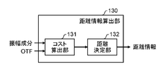
- the distance information calculation unit 130 includes a cost calculation unit 131 and a distance determination unit 132.
- the cost calculation unit 131 uses the first amplitude component, the second amplitude component, and the lens blur data extracted by the amplitude extraction unit 120 to calculate the cost of the assumed distance for each pixel of each image. Is a processing unit for calculating.
- DFD is used as a method for calculating distance information.
- OTF is used as lens blur data.
- the DFD calculates, for example, a distance cost (Cost (d)) for a plurality of assumed distances d.
- the formula for calculating the cost of distance is shown in the following formula 1.
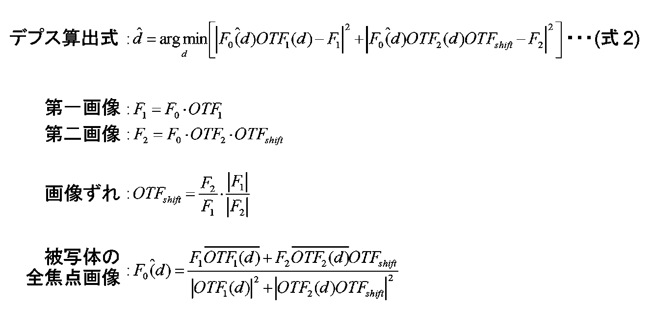
- Formula 1 is calculated based on the following Formula 2, which is a depth calculation formula considering image displacement.
- the phase component can be eliminated from the equation by applying an image shift to one of the first image and the second image. That is, a solution can be obtained using only the amplitude component. It is a new finding to apply the image shift itself and to introduce the image shift into the depth calculation formula. Conventionally, since there is no image shift, no image shift is introduced into the depth calculation formula. As a result, even if Fourier transformation is performed, the phase component remains in the formula and there is an image shift. Depth could not be calculated accurately.
- the distance determination unit 132 uses the distance cost calculated by the cost calculation unit 131 to determine distance information to the subject for each pixel.
- the distance d having the smallest distance cost in each pixel is output as distance information for that pixel. That is, the distance information calculation unit 130 calculates distance information to the subject for each pixel of the image.
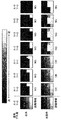
- FIG. 3 is a diagram illustrating a difference in accuracy with respect to a positional deviation between the distance information calculated by the conventional method and the distance information calculated by the method of the present disclosure.
- FIG. 3 visually shows distance information calculated by the conventional method and distance information calculated by the method according to the present disclosure using the second image. As shown in FIG. 3, the distance information does not represent the distance to the subject even if the image is shifted by one pixel in the conventional method, whereas in the method of the present disclosure, the distance is shifted even if the pixel is shifted by one pixel vertically and horizontally. The information accurately represents the distance to the subject.
- the conventional method cannot accurately calculate the distance information to the subject unless the subpixels are accurately aligned.
- the method of the present disclosure shows that the distance information to the subject can be accurately calculated even with rough alignment. Further, in the conventional method, when the subject moves about 1 pixel between the acquisition of the first image and the acquisition of the second image, the distance information to the subject cannot be accurately calculated. On the other hand, in the method of the present disclosure, even if the subject moves about 1 pixel between the acquisition of the first image and the acquisition of the second image, the distance information to the subject is accurately calculated without correcting the position. It becomes possible to do.
- the present disclosure can be applied to still image shooting or moving image shooting in which a subject moves at high speed.
- FIG. 4 is a block diagram illustrating a functional configuration of the image processing apparatus according to the second embodiment.
- the same reference numerals are used for the same components as those in the first embodiment, and description thereof is omitted.
- the distance information is calculated after correcting the positional deviation between different images.
- the image processing apparatus 100 further includes an area dividing unit 140 and an area searching unit 150.
- the area dividing unit 140 is a processing unit that divides the first image into a plurality of first small areas.
- the size of the first small area to be divided is not particularly limited.
- the first small area may be divided into 4 ⁇ 4 pixel first small areas.
- the region search unit 150 is a processing unit that searches for a second small region corresponding to each of the plurality of divided first small regions for images other than the first image.
- the area search unit 150 corrects the positional deviation between the images by searching for and aligning the corresponding second small area image in the second image for each of the first small area images of the first image. To do.
- the image corresponding to each first small area of the first image divided by the area dividing unit 140 is searched for the corresponding image in the second image, and the similar image area is determined as the second area.
- Small area Small area.
- the search algorithm is not particularly limited, but in this embodiment, block matching is used as the search algorithm.
- a search algorithm other methods may be used as long as a corresponding region between images can be searched.
- Block matching searches for the corresponding second small area in the second image for each first small area of the first image.
- the difference between the first small area of the first image and each area of the second image is calculated, and the area having the smallest difference is set as the second small area.
- the difference is calculated based on, for example, the sum of luminance differences with respect to the area.
- the frequency conversion unit 110 in the present embodiment converts the first small region image and the corresponding second small region image into frequencies.
- the amplitude extraction unit 120 extracts an amplitude component for each small region, which is the first small region and the corresponding second small region. That is, the amplitude extraction unit 120 extracts an amplitude component for each of the first small region and the corresponding second small region.
- the distance information calculation unit 130 calculates distance information to the subject for each small area. That is, the distance information calculation unit 130 calculates the distance information to the subject for each first small area aligned with the corresponding second small area.
- the first image of the plurality of images is divided into the first small regions, and each first small region is aligned with the other images, thereby shifting the position between the images. Can be finely corrected. Therefore, distance information to the subject can be calculated with higher accuracy.
- the distance information can be calculated with high accuracy even if some positional deviation occurs between a plurality of images, so that the alignment between images can be roughened. For example, in a normal DFD, it is impossible to calculate distance information with high accuracy unless alignment is performed up to 0.1 pixel in a weak edge region. On the other hand, in the case of the present disclosure, it is possible to calculate distance information with high accuracy even with alignment of about one pixel unit.
- Embodiment 3 will be described with reference to FIG.
- FIG. 5 is a block diagram showing a functional configuration of the distance information calculation unit in the present embodiment.
- the distance information calculation unit 130 includes a representative cost calculation unit 133 instead of the cost calculation unit 131, and includes a representative distance determination unit 134 instead of the distance determination unit 132.
- the representative cost calculation unit 133 uses the amplitude component of the first small area of the first image, the amplitude component of the second small area of the second image, and the blur data of the input lens for each assumed small area. The representative cost of is calculated. That is, the representative cost calculation unit 133 calculates the representative cost of the assumed distance for each first small region that is aligned with the corresponding second small region. The representative cost of distance is calculated by the following formula 3.
- the method for calculating the representative cost of distance is not particularly limited, but in this embodiment, the representative cost of one distance is calculated for one small area. Then, the representative distance determining unit 134 determines the representative distance information for each small area using the representative cost of the distance calculated by the representative cost calculating unit 133. Specifically, the representative cost calculation unit 133 adds the frequency coefficient values, and the representative distance determination unit 134 calculates one representative distance information for one small region as a representative value.
- the calculation cost and the memory used can be significantly reduced by calculating the representative distance information for each small area, not for each pixel. As a result, the processing speed can be increased and the apparatus cost can be reduced.
- the distance information to the subject when calculating the distance information to the subject using a plurality of images taken at different timings, accuracy is obtained even if the alignment between images is not performed or rough alignment is performed.
- the distance information to the subject can be calculated well.
- Embodiments 1 to 3 have been described as examples of the technology disclosed in the present disclosure.
- the technology in the present disclosure is not limited to this, and can also be applied to embodiments that have been changed, replaced, added, omitted, and the like.
- the present disclosure also includes modifications obtained by making various modifications conceivable by those skilled in the art without departing from the gist of the present disclosure, that is, the meanings of the words described in the claims. It is.
- distance information for only a part of pixels may be calculated. Specifically, for example, it is not necessary to search for all of the first small areas, and the distance information may be calculated by searching for the first small area of interest.
- first small areas to be divided may not be completely independent from each other, and may be partially overlapped (overlapped).
- the first small area can be selected not only square but also any shape.
- Embodiments 1 to 3 OTF is used as an input.
- PSF is converted into OTF when Fourier transform is performed. Therefore, PSF may be input and converted into OTF by performing Fourier transform internally. .
- a program for causing a computer to execute each image processing method included in the image processing apparatus 100 and a recording medium on which the program is recorded are within the scope of the present disclosure.
- the present disclosure is applicable to an image processing apparatus and an image processing method that calculate distance information to a subject using a plurality of images having different in-focus positions. Specifically, it can be applied to a digital still camera, a digital movie camera, a mobile phone with a camera function, a smartphone, and the like.
Landscapes
- Engineering & Computer Science (AREA)
- Physics & Mathematics (AREA)
- General Physics & Mathematics (AREA)
- Computer Vision & Pattern Recognition (AREA)
- Multimedia (AREA)
- Signal Processing (AREA)
- Optics & Photonics (AREA)
- Electromagnetism (AREA)
- Radar, Positioning & Navigation (AREA)
- Remote Sensing (AREA)
- Theoretical Computer Science (AREA)
- Computing Systems (AREA)
- Image Processing (AREA)
- Length Measuring Devices By Optical Means (AREA)
- Measurement Of Optical Distance (AREA)
- Image Analysis (AREA)
- Studio Devices (AREA)
Abstract
画像処理装置(100)は、合焦位置の異なる複数の画像を利用して被写体までの距離情報を算出する画像処理装置(100)であって、周波数変換部(110)と、振幅抽出部(120)と、距離情報算出部(130)とを備える。周波数変換部(110)は、画像を周波数に変換する。振幅抽出部(120)は、周波数に変換して得られた係数の位相成分と振幅成分のうち振幅成分を抽出する。距離情報算出部(130)は、係数の位相成分と振幅成分のうち振幅抽出部(120)で抽出された振幅成分のみ、および、レンズのぼけデータを利用して距離情報を算出する。
Description
本開示は、合焦位置の異なる複数の画像を利用して被写体までの距離情報を算出する画像処理装置、および、画像処理方法に関する。
画像撮影装置などにおいて、ある3次元シーンの奥行き、即ち画像撮影装置などから被写体までの距離情報を非接触で算出するための様々な手法が提案されている。それらを大別すると、能動的手法と受動的手法がある。能動的手法では、赤外線や超音波、レーザーなどを被写体に照射し、反射波が戻ってくるまでの時間や反射波の角度などに基づいて被写体までの距離情報を算出する。受動的手法では、被写体の画像に基づいて被写体までの距離情報を算出する。特にカメラにおいては赤外線などを照射するための装置を必要としない受動的手法が広く用いられている。
受動的手法にも多くの手法が提案されている。その一つとして、被写体までの距離によって大きさや形状が変化する、ぼけの情報に基づいて被写体までの距離情報を算出するDepth from Defocus(以下DFDと表記)と呼ばれる手法がある。DFDには、複数のカメラを必要としない、少数の画像を利用して被写体までの距離情報の算出が可能である、などの特徴がある。
以下、DFDの原理について簡単に説明する。
DFDは、合焦位置の異なる複数の画像から、ぼけの情報に基づいて被写体までの距離情報を算出する手法である。ぼけの情報を含んだ撮影画像(以下ぼけ画像と表記)は、レンズによるぼけのない状態を表す全焦点画像に、被写体までの距離の関数である点像分布関数(Point Spread Function)を畳み込んだ画像となる。点像分布関数(以下PSFと表記)は被写体までの距離の関数であるため、DFDではぼけ画像からぼけの情報を検出することによって、被写体までの距離情報を算出することができる。ただし、このとき、全焦点画像と被写体までの距離情報は未知である。ぼけ画像一枚に対して、ぼけ画像、全焦点画像、被写体までの距離情報に関する式が1つ成立するため、合焦位置の異なるぼけ画像を新たに撮影し、新たな式を得る。得られた複数の式を解き、被写体までの距離情報を算出する。式の獲得の方法や式を解く方法等に関して、特許文献1をはじめとして、DFDに対する様々な提案が存在する。
しかしながら、合焦位置の異なる複数の画像を得ようとする場合、レンズ系のピントを変化させて複数の画像を得るため、それぞれの画像を得る時間に時間差が発生する。この時間差内に被写体の位置や形状などが大きく変わる場合、複数の画像間の被写体に位置ずれが発生するため、被写体までの距離情報を精度良く算出することが困難な場合がある。すなわち、動きの速い被写体の静止画や動画の撮影に従来のDFDを用いることが困難な場合がある。
本開示は、動きの速い被写体の静止画や動画の撮影において被写体までの距離情報を精度良く算出することができる画像処理装置および画像処理方法を提供する。
本開示における画像処理装置は、合焦位置の異なる複数の画像を利用して被写体までの距離情報を算出する画像処理装置であって、周波数変換部と、振幅抽出部と、距離情報算出部とを備える。周波数変換部は、画像を周波数に変換する。振幅抽出部は、周波数に変換して得られた係数の位相成分と振幅成分のうち振幅成分を抽出する。距離情報算出部は、係数の位相成分と振幅成分のうち振幅抽出部で抽出された振幅成分のみ、および、レンズのぼけデータを利用して距離情報を算出する。
また、本開示における画像処理方法は、合焦位置の異なる複数の画像を利用して被写体までの距離情報を算出する画像処理方法であって、画像を周波数に変換し、周波数に変換して得られた係数の位相成分と振幅成分のうち振幅成分を抽出し、係数の位相成分と振幅成分のうち抽出された振幅成分のみ、および、レンズのぼけデータを利用して距離情報を算出する。
本開示における画像処理装置および画像処理方法は、動きの速い被写体の静止画や動画の撮影において被写体までの距離情報を精度良く算出することが可能となる。
以下、適宜図面を参照しながら、実施の形態を詳細に説明する。但し、必要以上に詳細な説明は省略する場合がある。例えば、既によく知られた事項の詳細説明や実質的に同一の構成に対する重複説明を省略する場合がある。これは、以下の説明が不必要に冗長になるのを避け、当業者の理解を容易にするためである。
なお、添付図面および以下の説明は、当業者が本開示を十分に理解するために、提供されるのであって、これらにより請求の範囲に記載の主題を限定することは意図されていない。
(実施の形態1)
以下、図1を用いて、実施の形態1を説明する。
以下、図1を用いて、実施の形態1を説明する。
図1は、実施の形態1における画像処理装置の機能構成を示すブロック図である。
本実施の形態における画像処理装置100は、合焦位置の異なる複数の画像を利用して被写体までの距離情報を算出する装置である。図1に示すように、画像処理装置100は、周波数変換部110と、振幅抽出部120と、距離情報算出部130とを備える。
周波数変換部110は、画像を周波数に変換する処理部である。つまり、周波数変換部110は、合焦位置の異なる複数の画像に対して、画像を画像空間から周波数空間に変換している。画像を画像空間から周波数空間に変換することで、距離情報算出の精度を向上させることが可能となる。本実施の形態の場合、周波数変換部110は、複数の画像を画像空間から周波数空間に変換する。ここでは、複数の画像として、例えば合焦位置の異なる第一画像と第二画像が周波数変換部110に入力されたものとして説明する。なお、複数の画像は、パラレルに入力されてもシリアルに入力されてもかまわない。また、周波数変換部110が画像を画像空間から周波数空間に変換する方法に特に制限はなく、例えば、FFT(Fast Fourie Transform)や、DFT(Discrete Fourie Transform)などが挙示される。
振幅抽出部120は、周波数変換部110で周波数に変換して得られた係数の位相成分と振幅成分のうち振幅成分を抽出する処理部である。本実施の形態の場合、振幅抽出部120は、周波数空間に変換して得られた第一画像と第二画像の係数の振幅成分のみを抽出する。具体的には、周波数空間に変換して得られた係数は、複素数になっているので、振幅抽出部120は、係数の絶対値を算出することによって、振幅成分のみを抽出している。なお、周波数空間に変換して得られた係数は、変換係数ともいわれる。本実施の形態の場合、振幅抽出部120は、第一画像と第二画像のそれぞれの振幅成分である第一振幅成分と第二振幅成分を抽出する。
距離情報算出部130は、係数の位相成分と振幅成分のうち振幅抽出部120で抽出された振幅成分のみ、および、レンズのぼけデータを利用して被写体までの距離情報を算出する処理部である。
ここで、レンズのぼけデータとは、画像を取得したカメラのレンズや絞りなどの光学系の構成によって決定される光学伝達関数(Optical Transfer Function)である。以下、光学伝達関数をOTFと表記する。
図2は、本実施の形態における距離情報算出部の機能構成を示すブロック図である。
図2に示すように、距離情報算出部130は、コスト算出部131と距離決定部132とを備えている。
コスト算出部131は、振幅抽出部120で抽出された第一振幅成分、第二振幅成分、および、レンズのぼけデータを利用してそれぞれの画像の各画素に対して、想定される距離のコストを算出する処理部である。
本実施の形態では、距離情報を算出する手法として、DFDを利用する。また、レンズのぼけデータとしてOTFを利用する。DFDは画像において、各画素がどの距離に対応するかを推定するために、例えば、想定される複数の距離dに対して距離のコスト(Cost(d))を算出する。距離のコストを算出する式は下記式1で示す。

なお、式1は、画像ずれを考慮したデプス算出式である下記式2に基づき算出される。ここで、本開示は、第一画像、および、第二画像のいずれか一方に、画像ずれを作用させることにより、位相成分を式中から消去することができる。つまり、振幅成分のみで解を得ることが可能となる。当該画像ずれを作用させること自体、および、画像ずれをデプス算出式に導入することは新しい知見である。従来では、画像ずれを作用させることがないため、デプス算出式に画像ずれを導入することはなく、結果として、フーリエ変換を行っても位相成分が式中に残存し、画像ずれがある場合はデプスが精度よく算出できなかった。
距離決定部132は、コスト算出部131で算出された距離のコストを利用して、各画素に対して被写体までの距離情報を決定する。ここでは、各画素の想定される複数の距離dのうち、各画素において距離のコストが最も小さくなる距離dをその画素の距離情報として出力する。すなわち、距離情報算出部130は、画像の各画素に対して被写体までの距離情報を算出する。
図3は、従来の手法により算出された距離情報と本開示の手法により算出された距離情報との位置ずれに対する精度の相違を示す図である。
16段階に距離が異なる被写体を撮像した第一画像と、縦(図3中Y)横(図3中X)に被写体がずれた(図3中数字でずれ量を示す。単位はピクセル数)第二画像とを用い、従来の手法で算出された距離情報と本開示における手法で算出された距離情報とを図3は視覚的に示している。図3に示すように、従来の手法では画像が1ピクセルずれただけでも距離情報は被写体までの距離を表していないのに対し、本開示の手法では、画素が縦横に1ピクセルずれても距離情報は正確に被写体までの距離を表している。
この結果が示すように、従来の手法では、サブピクセルまで正確に位置合わせをしないと被写体までの距離情報を精度良く算出できないことを示している。これに対して、本開示の手法では、ラフな位置合わせであっても被写体までの距離情報を精度良く算出することが可能であることを示している。また、従来の手法では、第一画像の取得から第二画像の取得までの間に被写体が1ピクセル程度移動している場合は、被写体までの距離情報を精度良く算出できない。これに対して、本開示の手法では、第一画像の取得から第二画像の取得までの間に被写体が1ピクセル程度移動しても位置補正をすることなく被写体までの距離情報を精度良く算出することが可能となる。
以上のようにして、振幅成分のみを用いて被写体までの距離情報を算出することにより、演算コストを抑えながら、高速に距離情報を算出することが可能となる。さらに、本開示の画像処理方法では、合焦位置の異なる複数の画像間に位置ずれがあった場合であっても、画像を画像空間から周波数空間に変換し、位置情報を含まない振幅成分のみを用いて距離情報の算出を行う。そのため、位置ずれが所定範囲内であれば精度良く距離情報を算出することが可能となる。従って、被写体が高速で移動する静止画の撮影や動画の撮影の場合にも本開示を適用することが可能となる。
(実施の形態2)
以下、図4を用いて、実施の形態2を説明する。
以下、図4を用いて、実施の形態2を説明する。
図4は、実施の形態2における画像処理装置の機能構成を示すブロック図である。なお、本実施の形態において、実施の形態1と同じ構成については同じ符号を用い、説明を省略する。
本実施の形態では、距離情報算出の精度をさらに向上させるために、異なる画像間の位置ずれを補正してから距離情報の算出を行う。
本実施の形態における画像処理装置100は、領域分割部140と、領域探索部150とをさらに備える。領域分割部140は、第一画像を複数の第一小領域に分割する処理部である。分割する第一小領域の大きさは特に限定されるものではなく、例えば4ピクセル×4ピクセルの第一小領域に分割してもかまわない。
領域探索部150は、第一画像以外の他の画像について、分割された複数の第一小領域ごとに対応する第二小領域を探索する処理部である。つまり領域探索部150は、第一画像の第一小領域の画像のそれぞれについて第二画像内において対応する第二小領域の画像を探索し位置合わせを行うことによって、画像間の位置ずれを補正するものである。
具体的には、領域分割部140で分割された第一画像の各第一小領域に対応する画像を用いて、第二画像内に対応する画像を探索し、似通った画像の領域を第二小領域とする。探索アルゴリズムに関しては、特に限定されるものではないが、本実施の形態では、探索アルゴリズムとしてブロックマッチングを利用する。なお、探索アルゴリズムとしては、画像間の対応する領域を探索できれば、他の方法を利用しても良い。
ブロックマッチングは、第一画像の各第一小領域に対して、第二画像の中の対応する第二小領域を探索するものである。探索は、第一画像の第一小領域と第二画像の各領域の差異を算出し、差異が最も小さい領域を第二小領域としている。差異とは例えばその領域に対する輝度差の総和などに基づいて算出される。
本実施の形態における周波数変換部110は、第一小領域の画像、および、対応する第二小領域の画像を周波数に変換する。振幅抽出部120は、第一小領域、および、対応する第二小領域である、小領域ごとに振幅成分を抽出する。すなわち、振幅抽出部120は、第一小領域および対応する第二小領域それぞれに対して振幅成分を抽出する。距離情報算出部130は、小領域ごとに被写体までの距離情報を算出する。すなわち、距離情報算出部130は、対応する第二小領域と位置合わせされた第一小領域ごとに被写体までの距離情報を算出する。
以上のように、本実施の形態において、複数の画像のうち第一画像を第一小領域に分割し、第一小領域ごとに他の画像と位置合わせを行うことによって、画像間の位置ずれを細かく補正することができる。そのため、より精度良く被写体までの距離情報を算出することができる。ただし、本開示においては、複数の画像間に多少の位置ずれが発生していても精度良く距離情報を算出することができるため、画像間の位置合わせを荒くすることができる。例えば、通常のDFDでは、エッジの弱い領域については0.1ピクセル単位まで位置合わせを行わないと精度良く距離情報を算出することができない。これに対して、本開示の場合1ピクセル単位程度の位置合わせでも精度良く距離情報を算出することが可能となる。
(実施の形態3)
以下、図5を用いて、実施の形態3を説明する。
以下、図5を用いて、実施の形態3を説明する。
図5は、本実施の形態における距離情報算出部の機能構成を示すブロック図である。
図5に示すように距離情報算出部130は、コスト算出部131に代えて代表コスト算出部133を備え、距離決定部132に代えて代表距離決定部134を備えている。
代表コスト算出部133は、第一画像の第一小領域の振幅成分と第二画像の第二小領域の振幅成分と入力のレンズのぼけデータを利用して小領域ごとに、想定される距離の代表コストを算出する。すなわち、代表コスト算出部133は、対応する第二小領域と位置合わせされた第一小領域ごとに、想定される距離の代表コストを算出する。距離の代表コストは以下の式3で算出される。
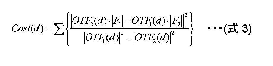
距離の代表コストの算出手法は特に限定されるものではないが、本実施の形態では、ひとつの小領域に対して、ひとつの距離の代表コストを算出している。そして、代表距離決定部134では、代表コスト算出部133で算出された距離の代表コストを用いて小領域ごとに代表距離情報を決定する。具体的には、代表コスト算出部133は、周波数係数値を合算し、代表距離決定部134が代表値として一つの小領域に一つの代表距離情報を算出する。
以上のように、本実施の形態においては、ピクセル単位ではなく小領域ごとに代表距離情報を算出することによって、演算コスト、および、使用メモリを大幅に削減することができる。そのため、処理の高速化が実現でき、装置コストの削減も可能となる。
本開示による具体的な効果としては、例えば以下のようなものがある。
合焦位置の異なる複数の画像を撮影している間、カメラのぶれや被写体の移動によって、複数の画像間の被写体に位置ずれが発生した場合は、被写体までの距離情報が精度良く求められない場合がある。この場合、距離情報を算出する前に位置合わせ処理が必要となる。しかし、位置合わせ処理は、画像の特徴やノイズなどの影響によって、正確に位置合わせができない場合や、正確に位置合わせをするために長時間を要する場合がある。
本開示は、異なるタイミングで撮影された複数の画像を利用して被写体までの距離情報を算出する場合において、画像間の位置合わせをしなくても、または、ラフな位置合わせであっても精度良く被写体までの距離情報を算出することができる。
以上のように、本開示において開示する技術の例示として、実施の形態1~3を説明した。しかしながら、本開示における技術は、これに限定されず、変更、置き換え、付加、省略などを行った実施の形態にも適用できる。また、上記実施の形態に対して本開示の主旨、すなわち、請求の範囲に記載される文言が示す意味を逸脱しない範囲で当業者が思いつく各種変形を施して得られる変形例も本開示に含まれる。
例えば、画像に対して、一部分の画素のみにおける距離情報が必要な場合は、その一部分の画素のみにおける距離情報を算出してもかまわない。具体的に例えば、全ての第一小領域について探索を行う必要はなく、着目する第一小領域について探索を行い、距離情報を算出してもかまわない。
また、分割する各第一小領域は互いに完全に独立していなくてもよく、一部重なり合って(オーバーラップして)いてもかまわない。
また、第一小領域は正方形ばかりでなく、任意の形状を選択しうる。
また、実施の形態1~3では、入力としてOTFを利用するが、一般的にPSFをフーリエ変換するとOTFになるため、PSFを入力にして、内部でフーリエ変換を行いOTFに変換しても良い。
また、画像処理装置100が備える各画像処理方法をコンピュータに実行させるためのプログラム、および、そのプログラムが記録された記録媒体も本開示の範囲内である。
本開示は、合焦位置の異なる複数の画像を利用して被写体までの距離情報を算出する画像処理装置、および、画像処理方法に適用可能である。具体的には、デジタルスチルカメラ、デジタルムービーカメラ、カメラ機能付き携帯電話機、スマートフォンなどに適用可能である。
100 画像処理装置
110 周波数変換部
120 振幅抽出部
130 距離情報算出部
131 コスト算出部
132 距離決定部
133 代表コスト算出部
134 代表距離決定部
140 領域分割部
150 領域探索部
110 周波数変換部
120 振幅抽出部
130 距離情報算出部
131 コスト算出部
132 距離決定部
133 代表コスト算出部
134 代表距離決定部
140 領域分割部
150 領域探索部
Claims (6)
- 合焦位置の異なる複数の画像を利用して被写体までの距離情報を算出する画像処理装置であって、
前記画像を周波数に変換する周波数変換部と、
周波数に変換して得られた係数の位相成分と振幅成分のうち振幅成分を抽出する振幅抽出部と、
前記係数の位相成分と振幅成分のうち前記振幅抽出部で抽出された振幅成分のみ、および、レンズのぼけデータを利用して前記距離情報を算出する距離情報算出部とを備える
画像処理装置。 - 前記距離情報算出部は、
前記振幅抽出部で抽出された振幅成分、および、レンズのぼけデータを利用して前記画像の想定される距離のコストを算出するコスト算出部と、
前記コスト算出部で算出された前記距離のコストを利用して、前記距離情報を決定する距離決定部とを備える
請求項1に記載の画像処理装置。 - さらに、
複数の前記画像の少なくとも一つを複数の第一小領域に分割する領域分割部と、
他の前記画像について、複数の前記第一小領域ごとに対応する第二小領域を探索する領域探索部とを備え
前記周波数変換部は、前記第一小領域の画像、および、対応する前記第二小領域の画像を周波数に変換し、
前記振幅抽出部は、前記第一小領域、および、対応する前記第二小領域である、小領域ごとに振幅成分を抽出し、
前記距離情報算出部は、前記小領域ごとに前記距離情報を算出する
請求項1に記載の画像処理装置。 - 前記距離情報算出部は、前記画像の各画素に対して前記距離情報を算出する
請求項1に記載の画像処理装置。 - 前記コスト算出部は、前記小領域ごとに想定される距離の代表コストを算出し、
前記距離決定部は、前記コスト算出部で算出された前記距離の代表コストを用いて前記小領域ごとの代表距離情報を決定する
請求項3に記載の画像処理装置。 - 合焦位置の異なる複数の画像を利用して被写体までの距離情報を算出する画像処理方法であって、
前記画像を周波数に変換し、
周波数に変換して得られた係数の位相成分と振幅成分のうち振幅成分を抽出し、
前記係数の位相成分と振幅成分のうち抽出された振幅成分のみ、および、レンズのぼけデータを利用して前記距離情報を算出する
画像処理方法。
Priority Applications (4)
| Application Number | Priority Date | Filing Date | Title |
|---|---|---|---|
| CN201680010718.6A CN107407560B (zh) | 2016-02-29 | 2016-06-21 | 图像处理装置以及图像处理方法 |
| EP16880193.4A EP3425331A4 (en) | 2016-02-29 | 2016-06-21 | IMAGE PROCESSING DEVICE AND IMAGE PROCESSING METHOD |
| JP2017536901A JP6354907B2 (ja) | 2016-02-29 | 2016-06-21 | 画像処理装置および画像処理方法 |
| US15/667,513 US10455139B2 (en) | 2016-02-29 | 2017-08-02 | Image processing device and image processing method for calculating distance information to a subject |
Applications Claiming Priority (2)
| Application Number | Priority Date | Filing Date | Title |
|---|---|---|---|
| JP2016038438 | 2016-02-29 | ||
| JP2016-038438 | 2016-02-29 |
Related Child Applications (1)
| Application Number | Title | Priority Date | Filing Date |
|---|---|---|---|
| US15/667,513 Continuation US10455139B2 (en) | 2016-02-29 | 2017-08-02 | Image processing device and image processing method for calculating distance information to a subject |
Publications (1)
| Publication Number | Publication Date |
|---|---|
| WO2017149565A1 true WO2017149565A1 (ja) | 2017-09-08 |
Family
ID=59743529
Family Applications (1)
| Application Number | Title | Priority Date | Filing Date |
|---|---|---|---|
| PCT/JP2016/002973 Ceased WO2017149565A1 (ja) | 2016-02-29 | 2016-06-21 | 画像処理装置および画像処理方法 |
Country Status (5)
| Country | Link |
|---|---|
| US (1) | US10455139B2 (ja) |
| EP (1) | EP3425331A4 (ja) |
| JP (1) | JP6354907B2 (ja) |
| CN (1) | CN107407560B (ja) |
| WO (1) | WO2017149565A1 (ja) |
Citations (3)
| Publication number | Priority date | Publication date | Assignee | Title |
|---|---|---|---|---|
| JPH11337313A (ja) | 1998-05-25 | 1999-12-10 | Univ Kyoto | 距離計測装置及び方法並びに画像復元装置及び方法 |
| JP2011095026A (ja) * | 2009-10-28 | 2011-05-12 | Kyocera Corp | 被写体距離推定装置 |
| WO2012101719A1 (ja) * | 2011-01-27 | 2012-08-02 | パナソニック株式会社 | 3次元画像撮影装置及び3次元画像撮影方法 |
Family Cites Families (10)
| Publication number | Priority date | Publication date | Assignee | Title |
|---|---|---|---|---|
| JP2011149931A (ja) * | 2009-12-21 | 2011-08-04 | Ricoh Co Ltd | 距離画像取得装置 |
| KR101675112B1 (ko) * | 2010-01-21 | 2016-11-22 | 삼성전자주식회사 | 거리 정보 추출 방법 및 상기 방법을 채용한 광학 장치 |
| US8330852B2 (en) * | 2010-04-30 | 2012-12-11 | Eastman Kodak Company | Range measurement using symmetric coded apertures |
| WO2011158508A1 (ja) * | 2010-06-17 | 2011-12-22 | パナソニック株式会社 | 画像処理装置および画像処理方法 |
| US9047681B2 (en) * | 2011-07-07 | 2015-06-02 | Samsung Electronics Co., Ltd. | Depth image conversion apparatus and method |
| JP5830295B2 (ja) * | 2011-07-29 | 2015-12-09 | オリンパス株式会社 | 画像処理装置、画像処理装置の作動方法、及び画像処理プログラム |
| US8983221B2 (en) * | 2011-08-29 | 2015-03-17 | Panasonic Intellectual Property Management Co., Ltd. | Image processing apparatus, imaging apparatus, and image processing method |
| AU2011224051B2 (en) * | 2011-09-14 | 2014-05-01 | Canon Kabushiki Kaisha | Determining a depth map from images of a scene |
| DE102013110615B3 (de) * | 2013-09-26 | 2014-11-27 | Sick Ag | 3D-Kamera nach dem Stereoskopieprinzip und Verfahren zum Erfassen von Tiefenkarten |
| JP6272112B2 (ja) * | 2014-03-31 | 2018-01-31 | キヤノン株式会社 | 距離検出装置、撮像装置、距離検出方法及び視差量検出装置 |
-
2016
- 2016-06-21 EP EP16880193.4A patent/EP3425331A4/en not_active Withdrawn
- 2016-06-21 WO PCT/JP2016/002973 patent/WO2017149565A1/ja not_active Ceased
- 2016-06-21 CN CN201680010718.6A patent/CN107407560B/zh active Active
- 2016-06-21 JP JP2017536901A patent/JP6354907B2/ja active Active
-
2017
- 2017-08-02 US US15/667,513 patent/US10455139B2/en active Active
Patent Citations (3)
| Publication number | Priority date | Publication date | Assignee | Title |
|---|---|---|---|---|
| JPH11337313A (ja) | 1998-05-25 | 1999-12-10 | Univ Kyoto | 距離計測装置及び方法並びに画像復元装置及び方法 |
| JP2011095026A (ja) * | 2009-10-28 | 2011-05-12 | Kyocera Corp | 被写体距離推定装置 |
| WO2012101719A1 (ja) * | 2011-01-27 | 2012-08-02 | パナソニック株式会社 | 3次元画像撮影装置及び3次元画像撮影方法 |
Non-Patent Citations (2)
| Title |
|---|
| See also references of EP3425331A4 |
| ZHOU,CHANGYIN ET AL.: "Coded Aperture Pairs for Depth from Defocus", IEEE INTERNATIONAL CONFERENCE ON COMPUTER VISION (ICCV, 29 September 2009 (2009-09-29), pages 325 - 332, XP031672598 * |
Also Published As
| Publication number | Publication date |
|---|---|
| CN107407560A (zh) | 2017-11-28 |
| JPWO2017149565A1 (ja) | 2018-03-08 |
| CN107407560B (zh) | 2019-09-24 |
| EP3425331A4 (en) | 2019-02-27 |
| US10455139B2 (en) | 2019-10-22 |
| EP3425331A1 (en) | 2019-01-09 |
| US20170332007A1 (en) | 2017-11-16 |
| JP6354907B2 (ja) | 2018-07-11 |
Similar Documents
| Publication | Publication Date | Title |
|---|---|---|
| JP6115781B2 (ja) | 画像処理装置及び画像処理方法 | |
| JP6140935B2 (ja) | 画像処理装置、画像処理方法、画像処理プログラム、および撮像装置 | |
| KR102563750B1 (ko) | 영상 블러링 제거 방법 및 장치 | |
| US8942506B2 (en) | Image processing apparatus, image processing method, and program | |
| US9508153B2 (en) | Distance measurement apparatus, imaging apparatus, distance measurement method, and program | |
| US20070189750A1 (en) | Method of and apparatus for simultaneously capturing and generating multiple blurred images | |
| US9619886B2 (en) | Image processing apparatus, imaging apparatus, image processing method and program | |
| JP5776771B2 (ja) | 対応点探索装置、および距離測定装置 | |
| WO2011010438A1 (ja) | 視差検出装置、測距装置及び視差検出方法 | |
| US20200326609A1 (en) | Image capturing apparatus, image processing apparatus, control method, and storage medium | |
| JP6494402B2 (ja) | 画像処理装置、撮像装置、画像処理方法、プログラム | |
| JP6395429B2 (ja) | 画像処理装置、その制御方法及び記憶媒体 | |
| WO2009096520A1 (ja) | 対応点探索装置および対応点探索方法 | |
| TWI528783B (zh) | 產生深度影像之方法及其系統及電腦程式產品 | |
| JP6381422B2 (ja) | 距離検出装置、撮像装置、および距離検出方法 | |
| JP6272112B2 (ja) | 距離検出装置、撮像装置、距離検出方法及び視差量検出装置 | |
| US10339665B2 (en) | Positional shift amount calculation apparatus and imaging apparatus | |
| JP6354907B2 (ja) | 画像処理装置および画像処理方法 | |
| JP2019211332A (ja) | 情報処理装置、情報処理方法及びプログラム | |
| US10530985B2 (en) | Image capturing apparatus, image capturing system, method of controlling image capturing apparatus, and non-transitory computer-readable storage medium | |
| JP6590639B2 (ja) | 距離検出装置、撮像装置、および距離検出方法 | |
| JP2016076838A (ja) | 画像処理装置及び画像処理装置の制御方法 | |
| JP2017034616A (ja) | 画像処理装置及びその制御方法 | |
| WO2016042721A1 (en) | Positional shift amount calculation apparatus and imaging apparatus | |
| JP2017138240A (ja) | 画像処理装置、画像処理方法、および、プログラム。 |
Legal Events
| Date | Code | Title | Description |
|---|---|---|---|
| REEP | Request for entry into the european phase |
Ref document number: 2016880193 Country of ref document: EP |
|
| ENP | Entry into the national phase |
Ref document number: 2017536901 Country of ref document: JP Kind code of ref document: A |
|
| NENP | Non-entry into the national phase |
Ref country code: DE |
|
| 121 | Ep: the epo has been informed by wipo that ep was designated in this application |
Ref document number: 16880193 Country of ref document: EP Kind code of ref document: A1 |