WO2017149605A1 - 風車並びにその制御装置及び制御方法 - Google Patents
風車並びにその制御装置及び制御方法 Download PDFInfo
- Publication number
- WO2017149605A1 WO2017149605A1 PCT/JP2016/056068 JP2016056068W WO2017149605A1 WO 2017149605 A1 WO2017149605 A1 WO 2017149605A1 JP 2016056068 W JP2016056068 W JP 2016056068W WO 2017149605 A1 WO2017149605 A1 WO 2017149605A1
- Authority
- WO
- WIPO (PCT)
- Prior art keywords
- wind turbine
- hydraulic
- tank
- oil
- windmill
- Prior art date
- Legal status (The legal status is an assumption and is not a legal conclusion. Google has not performed a legal analysis and makes no representation as to the accuracy of the status listed.)
- Ceased
Links
Images


Classifications
-
- F—MECHANICAL ENGINEERING; LIGHTING; HEATING; WEAPONS; BLASTING
- F03—MACHINES OR ENGINES FOR LIQUIDS; WIND, SPRING, OR WEIGHT MOTORS; PRODUCING MECHANICAL POWER OR A REACTIVE PROPULSIVE THRUST, NOT OTHERWISE PROVIDED FOR
- F03D—WIND MOTORS
- F03D7/00—Controlling wind motors
- F03D7/02—Controlling wind motors the wind motors having rotation axis substantially parallel to the air flow entering the rotor
- F03D7/022—Adjusting aerodynamic properties of the blades
- F03D7/024—Adjusting aerodynamic properties of the blades of individual blades
-
- F—MECHANICAL ENGINEERING; LIGHTING; HEATING; WEAPONS; BLASTING
- F03—MACHINES OR ENGINES FOR LIQUIDS; WIND, SPRING, OR WEIGHT MOTORS; PRODUCING MECHANICAL POWER OR A REACTIVE PROPULSIVE THRUST, NOT OTHERWISE PROVIDED FOR
- F03D—WIND MOTORS
- F03D7/00—Controlling wind motors
- F03D7/02—Controlling wind motors the wind motors having rotation axis substantially parallel to the air flow entering the rotor
- F03D7/022—Adjusting aerodynamic properties of the blades
- F03D7/0224—Adjusting blade pitch
-
- F—MECHANICAL ENGINEERING; LIGHTING; HEATING; WEAPONS; BLASTING
- F03—MACHINES OR ENGINES FOR LIQUIDS; WIND, SPRING, OR WEIGHT MOTORS; PRODUCING MECHANICAL POWER OR A REACTIVE PROPULSIVE THRUST, NOT OTHERWISE PROVIDED FOR
- F03D—WIND MOTORS
- F03D7/00—Controlling wind motors
- F03D7/02—Controlling wind motors the wind motors having rotation axis substantially parallel to the air flow entering the rotor
- F03D7/026—Controlling wind motors the wind motors having rotation axis substantially parallel to the air flow entering the rotor for starting-up
-
- F—MECHANICAL ENGINEERING; LIGHTING; HEATING; WEAPONS; BLASTING
- F03—MACHINES OR ENGINES FOR LIQUIDS; WIND, SPRING, OR WEIGHT MOTORS; PRODUCING MECHANICAL POWER OR A REACTIVE PROPULSIVE THRUST, NOT OTHERWISE PROVIDED FOR
- F03D—WIND MOTORS
- F03D7/00—Controlling wind motors
- F03D7/02—Controlling wind motors the wind motors having rotation axis substantially parallel to the air flow entering the rotor
- F03D7/04—Automatic control; Regulation
-
- F—MECHANICAL ENGINEERING; LIGHTING; HEATING; WEAPONS; BLASTING
- F15—FLUID-PRESSURE ACTUATORS; HYDRAULICS OR PNEUMATICS IN GENERAL
- F15B—SYSTEMS ACTING BY MEANS OF FLUIDS IN GENERAL; FLUID-PRESSURE ACTUATORS, e.g. SERVOMOTORS; DETAILS OF FLUID-PRESSURE SYSTEMS, NOT OTHERWISE PROVIDED FOR
- F15B1/00—Installations or systems with accumulators; Supply reservoir or sump assemblies
- F15B1/26—Supply reservoir or sump assemblies
-
- F—MECHANICAL ENGINEERING; LIGHTING; HEATING; WEAPONS; BLASTING
- F15—FLUID-PRESSURE ACTUATORS; HYDRAULICS OR PNEUMATICS IN GENERAL
- F15B—SYSTEMS ACTING BY MEANS OF FLUIDS IN GENERAL; FLUID-PRESSURE ACTUATORS, e.g. SERVOMOTORS; DETAILS OF FLUID-PRESSURE SYSTEMS, NOT OTHERWISE PROVIDED FOR
- F15B11/00—Servomotor systems without provision for follow-up action; Circuits therefor
- F15B11/16—Servomotor systems without provision for follow-up action; Circuits therefor with two or more servomotors
- F15B11/20—Servomotor systems without provision for follow-up action; Circuits therefor with two or more servomotors controlling several interacting or sequentially-operating members
-
- F—MECHANICAL ENGINEERING; LIGHTING; HEATING; WEAPONS; BLASTING
- F15—FLUID-PRESSURE ACTUATORS; HYDRAULICS OR PNEUMATICS IN GENERAL
- F15B—SYSTEMS ACTING BY MEANS OF FLUIDS IN GENERAL; FLUID-PRESSURE ACTUATORS, e.g. SERVOMOTORS; DETAILS OF FLUID-PRESSURE SYSTEMS, NOT OTHERWISE PROVIDED FOR
- F15B19/00—Testing; Calibrating; Fault detection or monitoring; Simulation or modelling of fluid-pressure systems or apparatus not otherwise provided for
-
- F—MECHANICAL ENGINEERING; LIGHTING; HEATING; WEAPONS; BLASTING
- F05—INDEXING SCHEMES RELATING TO ENGINES OR PUMPS IN VARIOUS SUBCLASSES OF CLASSES F01-F04
- F05B—INDEXING SCHEME RELATING TO WIND, SPRING, WEIGHT, INERTIA OR LIKE MOTORS, TO MACHINES OR ENGINES FOR LIQUIDS COVERED BY SUBCLASSES F03B, F03D AND F03G
- F05B2260/00—Function
- F05B2260/85—Starting
-
- F—MECHANICAL ENGINEERING; LIGHTING; HEATING; WEAPONS; BLASTING
- F05—INDEXING SCHEMES RELATING TO ENGINES OR PUMPS IN VARIOUS SUBCLASSES OF CLASSES F01-F04
- F05B—INDEXING SCHEME RELATING TO WIND, SPRING, WEIGHT, INERTIA OR LIKE MOTORS, TO MACHINES OR ENGINES FOR LIQUIDS COVERED BY SUBCLASSES F03B, F03D AND F03G
- F05B2270/00—Control
- F05B2270/30—Control parameters, e.g. input parameters
- F05B2270/303—Temperature
-
- F—MECHANICAL ENGINEERING; LIGHTING; HEATING; WEAPONS; BLASTING
- F05—INDEXING SCHEMES RELATING TO ENGINES OR PUMPS IN VARIOUS SUBCLASSES OF CLASSES F01-F04
- F05B—INDEXING SCHEME RELATING TO WIND, SPRING, WEIGHT, INERTIA OR LIKE MOTORS, TO MACHINES OR ENGINES FOR LIQUIDS COVERED BY SUBCLASSES F03B, F03D AND F03G
- F05B2270/00—Control
- F05B2270/60—Control system actuates through
- F05B2270/605—Control system actuates through pneumatic actuators
-
- F—MECHANICAL ENGINEERING; LIGHTING; HEATING; WEAPONS; BLASTING
- F15—FLUID-PRESSURE ACTUATORS; HYDRAULICS OR PNEUMATICS IN GENERAL
- F15B—SYSTEMS ACTING BY MEANS OF FLUIDS IN GENERAL; FLUID-PRESSURE ACTUATORS, e.g. SERVOMOTORS; DETAILS OF FLUID-PRESSURE SYSTEMS, NOT OTHERWISE PROVIDED FOR
- F15B2211/00—Circuits for servomotor systems
- F15B2211/80—Other types of control related to particular problems or conditions
- F15B2211/857—Monitoring of fluid pressure systems
-
- Y—GENERAL TAGGING OF NEW TECHNOLOGICAL DEVELOPMENTS; GENERAL TAGGING OF CROSS-SECTIONAL TECHNOLOGIES SPANNING OVER SEVERAL SECTIONS OF THE IPC; TECHNICAL SUBJECTS COVERED BY FORMER USPC CROSS-REFERENCE ART COLLECTIONS [XRACs] AND DIGESTS
- Y02—TECHNOLOGIES OR APPLICATIONS FOR MITIGATION OR ADAPTATION AGAINST CLIMATE CHANGE
- Y02E—REDUCTION OF GREENHOUSE GAS [GHG] EMISSIONS, RELATED TO ENERGY GENERATION, TRANSMISSION OR DISTRIBUTION
- Y02E10/00—Energy generation through renewable energy sources
- Y02E10/70—Wind energy
- Y02E10/72—Wind turbines with rotation axis in wind direction
Definitions
- the present disclosure relates to a windmill and a control device and control method thereof.
- the wind turbine blades are pivotally supported with respect to the hub via the slewing ring bearing, and the wind turbine blades are pivoted around the center axis of the slewing ring bearing by a hydraulic actuator.
- a hydraulic actuator There are known windmills that can be used.
- Patent Document 1 discloses a variable pitch blade type wind turbine configured to change a pitch angle of a wind turbine blade by a hydraulic cylinder via a link.
- Patent Document 1 does not disclose a configuration for warming up a pitch driving device including a hydraulic cylinder.
- An object of at least some embodiments of the present invention is to provide a wind turbine capable of appropriately warming up a pitch drive device, and a control device and control method thereof.
- a windmill includes: A plurality of windmill blades, A plurality of hydraulic actuators for controlling the pitch angles of the plurality of wind turbine blades; A first tank storing control oil for the plurality of hydraulic actuators; A first hydraulic pump provided between the plurality of hydraulic actuators and the first tank for pumping the control oil; A plurality of valves provided corresponding to each of the plurality of hydraulic actuators for controlling the supply state of the control oil to the hydraulic actuators; A control unit for controlling each of the valves, The control unit, when warming up the pitch hydraulic system of the plurality of wind turbine blades, for each of the wind turbine blades, in order to move the pitch angle of the wind turbine blade from the feather side to the fine side and return to the feather side Is configured to control the valve corresponding to the wind turbine blade so that the hydraulic actuator corresponding to the wind turbine blade performs.
- the oil replacement operation is performed on the plurality of wind turbine blades by the hydraulic actuator, and the control oil is caused to flow in the pitch hydraulic system of each wind turbine blade, so that the oil temperature of the control oil is uniform.
- the pitch hydraulic system can be warmed up appropriately.
- the oil change operation for a plurality of wind turbine blades is performed in order, the aerodynamic torque generated in the wind turbine rotor during warm-up of the pitch hydraulic system can be reduced, and unintended rotation of the wind turbine rotor is suppressed. it can.
- the wind turbine rotor is warmed up in the pitch hydraulic system by performing the oil swap operation of the (i + 1) th wind turbine blade after completion of the oil swap operation for the i th wind turbine blade. Can be reliably reduced.
- the valve is A proportional valve provided between each of the hydraulic actuators and the first hydraulic pump; An emergency solenoid valve provided between each of the hydraulic actuators and the first tank; Including The control unit controls the opening of the proportional valve to move the pitch angle from the feather side to the fine side when causing the hydraulic actuator to perform the oil change operation for each wind turbine blade, The emergency solenoid valve is controlled to open so as to return the pitch angle from the fine side to the feather side.
- control oil flows to the hydraulic line including the proportional valve in the pitch hydraulic system when the pitch angle is moved to the fine side.
- Control oil flows to the hydraulic line including the emergency solenoid valve in the pitch hydraulic system when moving the valve to the feather side.
- the windmill is One end is connected between the first hydraulic pump and the hydraulic actuator, and a bypass line for returning the control oil from the first hydraulic pump to the first tank;
- a bypass valve provided in the bypass line,
- the controller is When the temperature of the control oil in the first tank is less than a first threshold value, the bypass valve is opened, and the first hydraulic pump in the circulation path including the bypass line is opened in the first tank. Circulating the control oil to an unloaded state in which the control oil is not supplied to the hydraulic actuator side, When the temperature of the control oil in the first tank is equal to or higher than the first threshold value, the bypass valve is closed to enter an on-load state in which the control oil can be supplied to the hydraulic actuator side.
- the pitch hydraulic pressure system is switched between the unload state and the on-load state according to the temperature of the control oil in the first tank by the opening / closing control of the bypass valve.
- the system can be warmed up efficiently. Specifically, when the temperature of the control oil in the first tank is less than the first threshold, the pitch hydraulic system is put into an unload state, and the control oil is circulated in the circulation flow path including the bypass line to The temperature of the control oil is raised. On the other hand, when the temperature of the control oil in the first tank is equal to or higher than the first threshold value, the relatively high temperature control oil in the first tank is supplied to the majority of the pitch hydraulic system including the hydraulic actuator, so that the pitch hydraulic system The oil temperature of the control oil can be made uniform.
- the windmill further includes a first heater for heating the control oil in the first tank
- the control unit is a case where the first hydraulic pump is stopped when the pitch hydraulic system starts warming up, and the temperature of the control oil in the first tank is smaller than the first threshold.
- the first heater is controlled to heat the control oil in the first tank while the first hydraulic pump is stopped.
- the first hydraulic pump is stopped when the first hydraulic pump is stopped at the start of warm-up of the pitch hydraulic system and the temperature of the control oil in the first tank is equal to or lower than the specified temperature.
- the control oil in the first tank is heated by the first heater while being kept.
- the first hydraulic pump is not operated suddenly, but the control oil is heated up by the first heater. 1 Damage to the hydraulic pump can be prevented.
- the windmill is One end is connected between the first hydraulic pump and the hydraulic actuator, and a bypass line for returning the control oil from the first hydraulic pump to the first tank;
- a bypass valve provided in the bypass line,
- the controller is When the period during which the outside air temperature is less than the lower limit value of the operable temperature range of the windmill continues for a specified time, the operation of the windmill is stopped and the pitch angle of each of the windmill blades is shifted to the feather side. Control the valve, Until the outside air temperature is equal to or higher than the warm-up start temperature of the windmill until the warm-up start condition is satisfied for a specified time, the wind turbine is kept in an unloaded state in which the bypass valve is opened. After satisfying the warm-up start condition, each part of the wind turbine including the pitch hydraulic system is warmed up.
- the windmill is A main shaft configured to rotate with a wind turbine rotor including the plurality of wind turbine blades; A main bearing that rotatably supports the main shaft; A second tank in which lubricating oil for the main bearing is stored; A second heater for heating the lubricating oil in the second tank; A second hydraulic pump for supplying the lubricating oil in the second tank to the main bearing,
- the control unit after satisfying the warm-up start condition, If the temperature of the lubricating oil in the second tank is less than a second threshold, the second heater is controlled to heat the lubricating oil in the second tank; When the temperature of the lubricating oil in the second tank reaches a second threshold value, the second hydraulic pump is configured to operate intermittently.
- the heating by the second heater is performed until the temperature of the lubricating oil (main bearing lubricating oil) in the second tank reaches the second threshold after the warm-up start condition is satisfied.
- the temperature of the lubricating oil is raised by the second heater instead of operating the second hydraulic pump suddenly.
- the second hydraulic pump it is possible to prevent the second hydraulic pump from being damaged, or to suppress leakage of the lubricating oil due to clogging of the highly viscous lubricating oil from the main bearing with the return pipe.
- the second hydraulic pump is operated intermittently (inching operation) after the temperature of the lubricating oil in the second tank reaches the second threshold value, leakage of high-viscosity lubricating oil from the main bearing is suppressed. be able to. Thus, it is possible to appropriately warm up the lubricating oil system of the main bearing.
- the windmill is A speed increaser for increasing the rotational speed of the wind turbine rotor including the plurality of wind turbine blades; A third hydraulic pump for circulating lubricating oil stored in a tank portion provided in the speed increaser via a circulation pipe connected to the tank portion; A third heater for heating the lubricating oil in the tank part or the circulation pipe, The control unit, after satisfying the warm-up start condition, The third heater is controlled to heat the lubricating oil in the tank section or the circulation pipe for a specified time.
- the third heater is used to increase the speed of the lubricating oil (speed increasing gear lubricating oil) in the tank section or the circulation pipe, thereby increasing the speed.
- the machine oil system can be warmed up properly.
- the windmill is A main shaft configured to rotate with a wind turbine rotor including the plurality of wind turbine blades; A main bearing that rotatably supports the main shaft; A second tank in which lubricating oil for the main bearing is stored; A second hydraulic pump for supplying the lubricating oil in the second tank to the main bearing; A speed increaser for increasing the rotational speed of the windmill rotor; A third hydraulic pump for circulating the lubricating oil stored in a tank portion provided inside the speed increaser via a circulation pipe connected to the tank portion; The controller is in operation when warming up each part of the wind turbine when the warm-up start condition is satisfied among the first hydraulic pump, the second hydraulic pump, and the third hydraulic pump. The pump is configured to continue operation.
- the windmill is A nacelle that rotatably supports a wind turbine rotor including the plurality of wind turbine blades; A yaw drive for turning the nacelle,
- the controller is During the operation of the windmill, the yaw drive unit is controlled to turn the nacelle following the wind direction, When the windmill is made to stand by in the unloaded state, the nacelle is not configured to follow the wind direction by the yaw driving unit.
- the nacelle while the windmill is in operation, the nacelle is made to follow the wind direction by the yaw drive unit, thereby improving the windmill operating efficiency, and during the standby of the windmill in the unloaded state, the yaw drive unit Energy saving can be realized by not following the nacelle wind direction.
- a wind turbine control device includes: A control device for a wind turbine having any one of the above configurations (1) to (10), When the pitch hydraulic system of a plurality of wind turbine blades of the wind turbine is warmed up, an oil change operation for moving the pitch angle of the wind turbine blades from the feather side to the fine side and returning to the feather side in order for each wind turbine blade is performed.
- the hydraulic actuator corresponding to the blade is configured to control the valve corresponding to the wind turbine blade so as to be performed.
- the oil changing operation is performed on the plurality of wind turbine blades by the hydraulic actuator, and the control oil is caused to flow in the pitch hydraulic system of each wind turbine blade, so that the oil temperature of the control oil is uniform.
- the pitch hydraulic system can be warmed up appropriately.
- the oil change operation for a plurality of wind turbine blades is performed in order, the aerodynamic torque generated in the wind turbine rotor during warm-up of the pitch hydraulic system can be reduced, and unintended rotation of the wind turbine rotor is suppressed. it can.
- a wind turbine control method includes: A plurality of windmill blades, A plurality of hydraulic actuators for controlling the pitch angles of the plurality of wind turbine blades; A first tank storing control oil for the plurality of hydraulic actuators; A first hydraulic pump provided between the plurality of hydraulic actuators and the first tank for pumping the control oil; A wind turbine control method including a plurality of valves provided corresponding to each of the plurality of hydraulic actuators and controlling a supply state of the control oil to the hydraulic actuators, When the pitch hydraulic system of the plurality of wind turbine blades is warmed up, an oil change operation is performed on the wind turbine blade in order to move the pitch angle of the wind turbine blade from the feather side to the fine side in order to return to the feather side. Controlling the valve corresponding to the wind turbine blade so as to cause the corresponding hydraulic actuator to perform.
- the oil changing operation is performed on the plurality of wind turbine blades by the hydraulic actuator, and the control oil is caused to flow in the pitch hydraulic system of each wind turbine blade, so that the oil temperature of the control oil is uniform.
- the pitch hydraulic system can be warmed up appropriately.
- the oil change operation for a plurality of wind turbine blades is performed in order, the aerodynamic torque generated in the wind turbine rotor during warm-up of the pitch hydraulic system can be reduced, and unintended rotation of the wind turbine rotor is suppressed. it can.
- the oil change operation for the (i + 1) -th wind turbine blade is performed, so that the wind turbine rotor is warmed up in the pitch hydraulic system. Can be reliably reduced.
- the valve is A proportional valve provided between each of the hydraulic actuators and the first hydraulic pump; An emergency solenoid valve provided between each of the hydraulic actuators and the first tank; Including In the step of controlling the valve, For each wind turbine blade, when the hydraulic actuator performs the oil change operation, after controlling to open the proportional valve to move the pitch angle from the feather side to the fine side, Control is performed to open the emergency solenoid valve so as to return the pitch angle from the fine side to the feather side.
- the control oil flows into the hydraulic line including the proportional valve in the pitch hydraulic system when the pitch angle is moved to the fine side, and the pitch angle Control oil flows to the hydraulic line including the emergency solenoid valve in the pitch hydraulic system when moving the valve to the feather side.
- the windmill is One end is connected between the first hydraulic pump and the hydraulic actuator, and a bypass line for returning the control oil from the first hydraulic pump to the first tank; A bypass valve provided in the bypass line; Further including When the period during which the outside air temperature is equal to or lower than the lower limit value of the operable temperature range of the windmill continues for a specified time, the operation of the windmill is stopped and the pitch angle of each of the windmill blades is shifted to the feather side.
- Controlling the valve A step of waiting the windmill in an unloaded state in which the bypass valve is opened until a warm-up start condition in which a period in which the outside air temperature is equal to or higher than the warm-up start temperature of the windmill continues for a specified time; and And a step of warming up each part of the wind turbine including the pitch hydraulic system after satisfying the warm-up start condition.
- the oil replacement operation is performed by a hydraulic actuator for a plurality of wind turbine blades, and the control oil is caused to flow in the pitch hydraulic system of each wind turbine blade.
- the temperature can be made uniform and the pitch hydraulic system can be warmed up appropriately.
- the oil change operation for a plurality of wind turbine blades is performed in order, the aerodynamic torque generated in the wind turbine rotor during warm-up of the pitch hydraulic system can be reduced, and unintended rotation of the wind turbine rotor is suppressed. it can.
- FIG. 1 is a schematic overall configuration diagram of a wind turbine according to an embodiment. It is a figure which shows an example of the transition of the windmill state with respect to external temperature. It is a block diagram which shows the pitch hydraulic system of the windmill which concerns on one Embodiment. It is a figure which shows the pitch angle of the windmill blade in warm-up operation. It is a figure which shows the spindle hydraulic system and gearbox hydraulic system of the windmill which concern on one Embodiment. It is a flowchart of the warm-up operation of the windmill which concerns on one Embodiment.
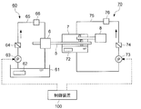
- FIG. 1 is a schematic overall configuration diagram of a wind turbine 1 according to an embodiment.
- a wind turbine 1 includes a wind turbine rotor 4 including a plurality of wind turbine blades 2 (2A to 2C) and a hub 3 to which the wind turbine blade 2 is attached, and a nacelle 9 that rotatably supports the wind turbine rotor 4. , And a tower 10 with a nacelle 9 supported at the upper end.
- the windmill 1 includes a hydraulic actuator 12 for controlling the pitch angle of the windmill blade 2. When the windmill 1 is warmed up, the hydraulic actuator 12 is controlled by a control device 100 described later. Further, the windmill 1 may include a yaw driving unit 14 for turning the nacelle 9. Furthermore, the windmill 1 may include a temperature sensor 15 for measuring the outside air temperature.
- the windmill 1 is a wind power generator including a generator 8.
- the windmill 1 has a configuration in which three windmill blades 2A to 2C are radially attached to the hub 3.
- the hub 3 is connected to the main shaft 5.
- the main shaft 5 is rotatably supported by a main bearing 6 attached to the nacelle 9.
- the wind turbine rotor 4 including the wind turbine blades 2 and the hub 3 rotates together with the main shaft 5.
- the windmill rotor 4 is connected to the speed increaser 7 via the main shaft 5.
- the speed increaser 7 is connected to the generator 8. For this reason, the rotation of the wind turbine rotor 4 is increased by the speed increaser 7 and input to the generator 8.
- the speed increaser 7 (for example, a gear type speed increaser) is illustrated as a power transmission mechanism for transmitting the rotational energy of the wind turbine rotor 4 to the generator 8.
- the power transmission mechanism is limited to this. It is not a thing.
- a direct drive in which the wind turbine rotor 4 is directly connected to the generator 8 through the main shaft 5 or a hydraulic transmission including a hydraulic pump and a hydraulic motor can be used.
- the nacelle 9 is supported at the upper end of the tower 10 so as to be turnable in the yaw direction.
- the tower 10 may be installed on land, or may be installed on the water such as on the ocean or on the lake.
- FIG. 2 is a diagram illustrating an example of transition of the windmill state with respect to the outside air temperature.
- the windmill 1 transitions between a plurality of windmill states including an operation state, a low-temperature standby state, and a warm-up state according to the outside air temperature.
- the windmill 1 In the operation state, the windmill 1 generates power by normal operation.
- the yaw driving unit 14 may be set to perform automatic follow-up control that adjusts the direction of the wind turbine rotor 4 according to the wind direction.
- the wind turbine 1 stops power generation and shifts to the low temperature standby state.
- the low-temperature shutdown condition (A) is “when the outside temperature is lower than the low-temperature standby start temperature ⁇ T 1 ° C. and continues for the specified time t 1 ”.
- the low-temperature standby start temperature ⁇ T 1 ° C. may be the lower limit value of the operable temperature range of the wind turbine 1.
- the low-temperature standby state is mainly intended to protect each device of the windmill 1 placed in a low-temperature state.
- the wind turbine 1 includes at least a part of heaters (for example, the second heater 62 of the main bearing 6 and the third heater 72 of the speed increaser 7 shown in FIG. 5) or a pump (for example, the control oil shown in FIG. 3).
- a pump for example, the control oil shown in FIG. 3.
- Standby while operating auxiliary machinery such as the first hydraulic pump 23).
- the pitch angle of the wind turbine blade 2 may be shifted to the feather side. Further, the automatic follow-up control by the yaw drive unit 14 may be stopped.
- the warm-up start condition (B) is “when the outside air temperature continues to be the warm-up start temperature ⁇ T 2 ° C. for a predetermined time t 2 ”.
- the warm-up start temperature ⁇ T 2 ° C. is higher than the low-temperature standby start temperature ⁇ T 1 ° C.
- the warm-up state is mainly intended to warm each device (for example, lubricating oil of each device) toward resuming the operation of the windmill 1.
- each device is warmed up so that the windmill 1 can be activated.
- the yaw drive unit 14 may be set to perform automatic tracking control as necessary.
- the automatic follow-up control may not be performed in order to avoid the generation of torque in the main shaft 5.
- the operation state of the windmill 1 is shifted.
- the warm-up completion condition (C) is assumed to be when warm-up of all devices is completed.
- the driving state includes a standby state that is a state of waiting for wind before starting the windmill 1 and an activation state that is a state at the time of activation.
- the warm-up operation of the wind turbine 1 is, for example, an operation in the warm-up state described above.
- FIG. 3 is a configuration diagram illustrating the pitch hydraulic system 20 of the wind turbine 1 according to the embodiment.
- the wind turbine 1 includes a plurality of hydraulic actuators 12A to 12C for controlling the pitch angles of the plurality of wind turbine blades 2A to 2C (see FIG. 1).
- the hydraulic actuators 12A to 12C are mounted in the hub 3, and include a hydraulic cylinder 121 and a cylinder rod 122 configured to reciprocate within the hydraulic cylinder 121.
- the control oil is supplied from the fine side port A into the fine side hydraulic chamber 123 of the hydraulic cylinder 121, so that the cylinder rod 122 moves to the left side of the figure and the wind turbine blade 2 has a full fine angle.
- the windmill 1 also includes a pitch hydraulic system 20 for operating the hydraulic actuators 12A to 12C.
- a pitch hydraulic system 20 for operating the hydraulic actuators 12A to 12C.
- FIG. 1 only the hydraulic system for operating the hydraulic actuator 12A is extracted and described, and the hydraulic system of the other hydraulic actuators 12B and 12C is omitted, but the other hydraulic actuators 12B and 12C are omitted. May have the same configuration as the hydraulic actuator 12A.
- the continuous line has shown the control oil line
- the broken line has shown the pilot oil line.
- the pitch hydraulic system 20 controls the first tank 21 in which control oil is stored, the first hydraulic pump 23 provided between the hydraulic actuators 12A to 12C and the first tank 21, and the hydraulic actuators 12A to 12C.
- a plurality of valves for controlling the supply state of oil are examples of the first hydraulic pump 23 provided between the hydraulic actuators 12A to 12C and the first tank 21, and the hydraulic actuators 12A to 12C.
- the first tank 21 stores control oil for the plurality of hydraulic actuators 12A to 12C.
- a first heater 22 for raising the temperature of the control oil may be provided inside the first tank 21.
- the first hydraulic pump 23 is provided between the plurality of hydraulic actuators 12A to 12C and the first tank 21, and is configured to pump control oil.
- the plurality of valves are provided corresponding to the plurality of hydraulic actuators 12A to 12C, respectively, and are configured to control the supply state of the control oil to the hydraulic actuators 12A to 12C.
- the pitch hydraulic system 20 includes a control oil line (oil supply line) 40 for supplying control oil from the first tank 21 toward the hydraulic actuator 12 by the first hydraulic pump 23, and the hydraulic actuator 12 side to the first tank 21.
- a control oil line (return oil line) 42 for returning the control oil, and a proportional valve 25 provided between the hydraulic actuator 12 and the first hydraulic pump 23 are included.
- the proportional valve 25 When controlling the pitch angle of the wind turbine blade 2 to the fine side, the proportional valve 25 connects the control oil line (oil supply line) 40 and the control oil line 44 communicating with the fine side port A of the hydraulic cylinder 121, A control oil line 43 communicating with the feather side port B of the hydraulic cylinder 121 and a control oil line (return oil line) 42 are connected. Accordingly, the control oil fed from the first tank 21 by the first hydraulic pump 23 is supplied from the fine side port A to the fine side hydraulic chamber 123 of the hydraulic cylinder 121 through the control oil lines 40 and 44. Further, the control oil discharged from the feather side hydraulic chamber 124 via the feather side port B returns to the first tank 21 through the control oil lines 43 and 42. Therefore, the pitch angle of the wind turbine blade 2 is controlled to the fine side by the hydraulic actuator 12.
- the proportional valve 25 connects the control oil line (oil supply line) 40 and the control oil line 43 communicating with the feather side port B.
- the control oil fed from the first tank 21 by the first hydraulic pump 23 is supplied from the feather side port B to the feather side hydraulic chamber 124 through the control oil lines 40 and 43, and the fine side port.
- the control oil flows from A to the feather side port B through the control oil lines 44 and 43.
- the pitch hydraulic system 20 has a circuit for controlling the pitch angle to the feather side in an emergency.
- the emergency time is, for example, a case where the supply of control oil to the hub 3 is cut off, a failure of the proportional valve, or an emergency stop of the windmill 1.
- the pitch hydraulic system 20 includes an emergency electromagnetic valve 31 provided between the hydraulic actuator 12 and the first tank 21, an emergency stop accumulator 30, and check valves 26 and 27 that operate in an emergency.
- the emergency solenoid valve 31 is demagnetized in the event of an emergency to connect the pilot oil line 50 connected to the fine side port A and the control oil line (return oil line) 42, and from the fine side hydraulic chamber 123 to the pilot.
- the oil is discharged.
- the emergency solenoid valve 31 connects the control oil line (oil supply line) 40 and the pilot oil line 50 and supplies the pilot oil via the check valve 32.
- the check valves 26 and 27 are usually configured to block bidirectional flow and open when the emergency solenoid valve 31 is demagnetized and the pilot oil is discharged.
- control oil flows from the accumulator 30 and the fine side port A to the feather side port B, and the pitch angle is controlled to the feather side.
- the accumulator 30 and the control oil line (return oil line) 42 are connected by a control oil line 48, and an on-off valve 29 is provided in the control oil line 48.
- the on-off valve 29 discharges the control oil to the control oil line (return oil line) 42 when the control oil line on the hydraulic actuator 12 side including the accumulator 30 becomes equal to or higher than the set pressure.
- control device 100 for controlling the pitch angle of the wind turbine blade 2 will be described.
- the control device 100 mainly controls a plurality of pitch hydraulic systems 20 as described above to control the pitch angle of the wind turbine blades 2 during warm-up. It is configured to control each of the valves.
- the control device 100 moves the pitch angle of each wind turbine blade 2 in turn from the feather side to the fine side.
- the valve corresponding to the wind turbine blade 2 is controlled so that the hydraulic actuator 12 (12A to 12C) corresponding to the wind turbine blade 2 performs an oil change operation for returning to the feather side.
- the plurality of valves may be controlled to cause the (i + 1) th hydraulic actuator 12 to perform the oil change operation for the (i + 1) th wind turbine blade 2.
- the oil replacement operation is performed on the plurality of wind turbine blades 2 by the hydraulic actuator 12, and the control oil is caused to flow in the pitch hydraulic system 20 of each wind turbine blade 2, so that the oil temperature of the control oil is uniform.
- the pitch hydraulic system 20 can be warmed up appropriately.
- the aerodynamic torque generated in the wind turbine rotor 4 during the warm-up of the pitch hydraulic system 20 can be reduced. Rotation can be suppressed.
- the aerodynamic torque generated in the wind turbine rotor 4 during the warm-up of the pitch hydraulic system 20 by performing the oil replacement operation of the (i + 1) -th wind turbine blade 2. Can be reliably reduced.
- the control device 100 sets the pitch angle to the feather angle when the hydraulic actuator 12 performs the oil change operation for each wind turbine blade 2.
- the emergency solenoid valve 31 may be controlled to open so as to return the pitch angle from the fine side to the feather side. That is, in the oil change operation, the pitch angle is moved from the feather side to the fine side and then returned from the fine side to the feather side.
- the proportional valve 25 corresponding to the target wind turbine blade 2 is controlled to open to the fine side, and the control oil is supplied to the fine side hydraulic chamber 123 via the control oil lines 40 and 44. While supplying, the control oil is discharged from the feather side hydraulic chamber 124 via the control oil lines 43 and 42.
- the proportional valve 25 is controlled to open to the feather side, and the control oil is supplied to the fine side hydraulic chamber 123 and the feather side hydraulic chamber 124 via the control oil lines 40, 43, 44. And the control oil is discharged from the feather-side hydraulic chamber 124 via the control oil lines 46, 48 and 42.
- the control oil when the oil change operation of each wind turbine blade 2 is performed, the control oil is supplied to the hydraulic line (control oil line) including the proportional valve 25 in the pitch hydraulic system 20 when the pitch angle is moved to the fine side.
- the control oil flows through the hydraulic lines (control oil line and pilot oil line) including the emergency solenoid valve 31 in the pitch hydraulic system 20.
- the control device 100 causes the first hydraulic pump 23 to start when the pitch hydraulic system 20 starts warming up. Is stopped, and when the temperature of the control oil in the first tank 21 is equal to or lower than a specified temperature lower than the first threshold, the first hydraulic pump 23 is stopped and the first tank 21 is stopped.
- the first heater 22 may be controlled to heat the control oil. Note that the first heater 22 may not be provided. In that case, the control oil is heated by the heat loss and frictional heat of the first hydraulic pump 23 due to the unload operation.
- the first hydraulic pump 23 when the first hydraulic pump 23 is stopped when the warming-up of the pitch hydraulic system 20 is started and the temperature of the control oil in the first tank 21 is equal to or lower than the specified temperature, the first hydraulic pump 23 is stopped. In this state, the temperature of the control oil in the first tank 21 is raised by the first heater 22. Thereby, for example, when the viscosity or property of the control oil deviates from the assumed range due to a temperature decrease, the first hydraulic pump 23 is not suddenly operated, but the control oil is heated by the first heater 22. The damage of the first hydraulic pump 23 can be prevented.
- the pitch hydraulic system 20 has one end connected between the first hydraulic pump 23 and the hydraulic actuator 12, and a bypass line 41 for returning control oil from the first hydraulic pump 23 to the first tank 21; And a bypass valve 24 provided in the bypass line 41.
- the control device 100 opens the bypass valve 24 and enters the circulation flow path including the bypass line 41 by the first hydraulic pump 23. Then, the control oil in the first tank 21 is circulated so that the control oil is not supplied to the hydraulic actuator 12 side.
- the control hydraulic pressure on the hydraulic actuator 12 side may be held during the unload operation by the check valve 35 provided on the control oil line 40 on the proportional valve 25 side relative to the bypass line 41.
- the operation in which the first hydraulic pump 23 is driven in the unloaded state and the control oil is circulated in the circulation flow path including the bypass line 41 is referred to as an unload operation.
- the control device 100 closes the bypass valve 24 so that the control oil can be supplied to the hydraulic actuator 12 side.
- an operation in which the first hydraulic pump 23 is driven in an on-road state and control oil is supplied to the hydraulic actuator 12 side is referred to as an on-road operation.
- the pitch hydraulic system 20 since the pitch hydraulic system 20 is switched between the unload state and the on-load state according to the temperature of the control oil in the first tank 21 by the opening / closing control of the bypass valve 24, the pitch hydraulic system 20 warm-ups can be performed efficiently. Specifically, when the temperature of the control oil in the first tank 21 is less than the first threshold value, the pitch hydraulic system 20 is put in an unload state, and the control oil is circulated in the circulation flow path including the bypass line 41 to change the first. The temperature of the control oil in one tank 21 is raised. On the other hand, when the temperature of the control oil in the first tank 21 is equal to or higher than the first threshold value, the relatively high temperature control oil in the first tank 21 is supplied to most of the pitch hydraulic system 20 including the hydraulic actuator 12. Thus, the oil temperature of the control oil in the pitch hydraulic system 20 can be made uniform.
- control device 100 may be configured to control the valves so as to stop the operation of the wind turbine 1 and shift the pitch angles of the wind turbine blades 2 to the feather side in the low temperature standby state (see FIG. 2).
- the control device 100 when the outside air temperature period is cold standby starting temperature -T less than 1 continues prescribed time t 1 which is the lower limit of the operable temperature range of the wind turbine 1, and stops the operation of the wind turbine 1
- the valves (for example, the proportional valve 25 and the emergency solenoid valve 31) are controlled so as to shift the pitch angle of each of the wind turbine blades 2A to 2C to the feather side.
- the wind turbine 1 may be kept in a standby state with the bypass valve 24 opened.
- the control device 100 may be configured to warm up each part of the wind turbine 1 including the pitch hydraulic system 20 in the warm-up state after satisfying the warm-up start condition (B).
- the control oil is contained in the circulation flow path including the bypass line 41.
- the temperature of the control oil in the first tank 21 can be suppressed from circulating. Thereby, after satisfy
- the control device 100 may be configured to sequentially control the pitch of the plurality of wind turbine blades 2A to 2C.
- FIG. 4 is a diagram showing the pitch angles of the wind turbine blades 2A to 2C in the warm-up operation.
- an oil change operation is performed by first moving the pitch angle of the wind turbine blade 2A from the feather side to the fine side and returning it to the feather side by valve control by the control device 100.
- the next wind turbine blade 2B performs the oil change operation in the same manner.
- the wind turbine blade 2C performs the oil change operation in the same manner.
- the windmill 1 having the above-described configuration may further include a main shaft hydraulic system 60 and a speed increaser hydraulic system 70 as illustrated in FIG.
- FIG. 5 is a diagram showing the main shaft hydraulic system 60 and the speed increaser hydraulic system 70 of the wind turbine 1 according to the embodiment.
- the wind turbine 1 is lubricated to the main shaft 5 configured to rotate with the wind turbine rotor 4 (see FIG. 1), the main bearing 6 that rotatably supports the main shaft 5, and the main bearing 6.
- a main shaft hydraulic system 60 for supplying oil.
- the main shaft hydraulic system 60 includes a second tank 61 in which lubricating oil for the main bearing 6 is stored, a lubricating oil line 65 for supplying the lubricating oil in the second tank 61 to the main bearing 6, and a lubricating oil line.
- a second hydraulic pump 63 provided at 65.
- the main shaft hydraulic system 60 may further include at least one of a filter 64 provided in the lubricating oil line 65 or a second heater 62 for heating the lubricating oil in the second tank 61. Further, the main spindle hydraulic system 60 may include a cooler 66.
- the windmill 1 includes a speed increaser 7 for increasing the rotational speed of the windmill rotor 4 (see FIG. 1), and a speed increaser hydraulic system 70 for supplying lubricating oil to the speed increaser 7.
- the speed increaser hydraulic system 70 includes a tank portion 71 provided in the speed increaser 7, a circulation pipe 75 connected to the tank portion 71, and lubricating oil stored in the tank portion 71 via the circulation pipe 75. And a third hydraulic pump 73 for circulating the air.
- the speed increaser hydraulic system 70 may further include at least one of a filter 74 provided in the circulation pipe 75 or a third heater 72 for heating the lubricating oil in the tank portion 71. Further, the speed increaser hydraulic system 70 may include a cooler 76.
- the control device 100 warms up the first hydraulic pump 23 (see FIG. 3), the second hydraulic pump 63, and the third hydraulic pump 73 (see FIG. 5). It is comprised so that a driving
- the control device 100 heats the lubricating oil in the second tank 61 when the temperature of the lubricating oil in the second tank 61 is less than the second threshold value.
- the second hydraulic pump 63 may be operated intermittently.
- the second heater 62 By heating, for example, when the viscosity or property of the lubricating oil deviates from the assumed range due to a decrease in temperature, the temperature of the lubricating oil is raised by the second heater 62 instead of operating the second hydraulic pump 63 suddenly. By doing so, it is possible to prevent the second hydraulic pump 63 from being damaged, or to suppress leakage of high-viscosity lubricating oil from the main bearing 6.
- the second hydraulic pump 63 is intermittently operated (inching operation) after the temperature of the lubricating oil in the second tank 61 reaches the second threshold value, leakage of the highly viscous lubricating oil from the main bearing 6 occurs. Can be suppressed. In this way, the main shaft hydraulic system 60 can be appropriately warmed up.
- the control device 100 may be configured to control the third heater 72 so as to heat the lubricating oil in the tank portion 71 or the circulation pipe 75 for a specified time after satisfying the warm-up start condition (B).
- the third heater 72 raises the temperature of the lubricating oil (the lubricating oil for the speed increasing gear) in the tank portion 71 or the circulation pipe 75, thereby increasing the speed increasing speed.
- the hydraulic system 70 can be appropriately warmed up.
- the yaw drive unit 14 when the windmill 1 includes the yaw drive unit 14 as shown in FIG. 1, the yaw drive unit 14 is controlled to turn the nacelle 9 following the wind direction during the operation of the windmill 1.
- the yaw drive unit 14 when the windmill 1 is put on standby in the unloaded state as described above, the yaw drive unit 14 may not be configured to follow the wind direction of the nacelle 9. According to this, the driving efficiency of the windmill 1 is improved by causing the nacelle 9 to follow the wind direction by the yaw driving unit 14 during operation of the windmill 1, and the yaw driving unit 14 during standby of the windmill 1 in the unloaded state. Energy saving can be realized by not following the wind direction of the nacelle 9 by.
- FIG. 6 the control method of the windmill 1 which concerns on some embodiment is demonstrated.
- the structure of the windmill 1 to which the following method is applied since it mentioned above, it abbreviate
- the parts shown in FIGS. 1, 3 and 5 are appropriately assigned to the respective parts of the wind turbine 1.
- the pitch hydraulic system 20 of the plurality of wind turbine blades 2 (2A to 2C) is warmed up, the pitch angle of the wind turbine blade 2 is sequentially set for each wind turbine blade 2.
- a valve for example, a proportional valve 25 or a valve corresponding to the wind turbine blade 2 is operated so that the hydraulic actuator 12 (12A to 12C) corresponding to the wind turbine blade 2 performs an oil change operation that moves from the feather side to the fine side and returns to the feather side.
- a step of controlling the emergency solenoid valve 31 is controlled so that the hydraulic actuator 12 (12A to 12C) corresponding to the wind turbine blade 2 performs an oil change operation that moves from the feather side to the fine side and returns to the feather side.
- a plurality of valves for example, the proportional valve 25 or the emergency solenoid valve 31 shown in FIG. 3
- the emergency solenoid valve 31 may be controlled to open so as to return the pitch angle from the fine side to the feather side.
- the wind turbine 1 is controlled by stopping the operation of the wind turbine 1 when the period during which the outside air temperature is equal to or lower than the low-temperature standby start temperature T 1 that is the lower limit value of the operable temperature range of the wind turbine 1 continues for the specified time t 1.
- a specific method for controlling the wind turbine 1 shown in FIG. 6 will be described with reference to FIG.
- the warm-up operation is started by satisfying the warm-up start condition (B)
- the pitch hydraulic system 20 Unload operation is performed at In the unload operation
- the control oil in the first tank 21 is circulated in the circulation flow path including the bypass line 41 by the first hydraulic pump 23 in the unloaded state in which the bypass valve 24 is opened,
- the temperature of the control oil is raised by one heater 22 (S1). Note that this unload operation may be omitted when the temperature of the control oil is equal to or higher than the first threshold value.
- the bypass valve 24 When the temperature of the control oil rises, the bypass valve 24 is closed and an on-road operation is performed. In the on-road operation, the first hydraulic pump 23 is driven in an on-road state where the bypass valve 24 is closed, and the pitch warm-up operation is performed for each blade (S2). When the pitch warm-up operation is completed in all the wind turbine blades 2, the bypass valve 24 is opened, the unload operation is performed again, the control oil is circulated, and the temperature is raised (S3). When the set time elapses while the control oil is circulated, the bypass valve 24 is closed again to turn it on, and the pitch hydraulic system 20 performs pitch warm-up operation for each wind turbine blade 2 (S2). Thus, steps S2 to S3 are repeated. When the warm-up of the other system is completed and the outside air temperature satisfies the warm-up completion condition (C), the wind turbine 1 shifts to the operation state (including the standby state and the start-up state).
- the hydraulic actuator 12 (12A to 12C) is caused to perform the oil change operation for the plurality of wind turbine blades 2 (2A to 2C), and each wind turbine blade is operated.
- the oil temperature of the control oil can be made uniform, and the pitch hydraulic system 20 can be warmed up appropriately.
- the oil change operation for the plurality of wind turbine blades 2 (2A to 2C) is sequentially performed, the aerodynamic torque generated in the wind turbine rotor 4 during the warm-up of the pitch hydraulic system 20 can be reduced, and the wind turbine Unintentional rotation of the rotor 4 can be suppressed.
- the present invention is not limited to the above-described embodiments, and includes forms obtained by modifying the above-described embodiments and forms obtained by appropriately combining these forms.
- expressions representing shapes such as quadrangular shapes and cylindrical shapes represent not only geometrically strict shapes such as quadrangular shapes and cylindrical shapes, but also irregularities and chamfers as long as the same effects can be obtained.
- a shape including a part or the like is also expressed.
- the expression “comprising”, “including”, or “having” one constituent element is not an exclusive expression that excludes the presence of the other constituent elements.
Landscapes
- Engineering & Computer Science (AREA)
- Mechanical Engineering (AREA)
- General Engineering & Computer Science (AREA)
- Physics & Mathematics (AREA)
- Fluid Mechanics (AREA)
- Chemical & Material Sciences (AREA)
- Life Sciences & Earth Sciences (AREA)
- Sustainable Development (AREA)
- Sustainable Energy (AREA)
- Combustion & Propulsion (AREA)
- Wind Motors (AREA)
- Analytical Chemistry (AREA)
Abstract
風車は、複数の風車翼と、前記複数の風車翼のピッチ角をそれぞれ制御するための複数の油圧アクチュエータと、前記複数の油圧アクチュエータのための制御油が貯留された第1タンクと、前記複数の油圧アクチュエータと前記第1タンクとの間に設けられ、前記制御油を圧送するための第1油圧ポンプと、前記複数の油圧アクチュエータのそれぞれに対応して設けられ、前記油圧アクチュエータへの前記制御油の供給状態を制御するための複数のバルブと、前記バルブの各々を制御するための制御部と、を備える。前記制御部は、前記複数の風車翼のピッチ油圧系統の暖機時、各々の前記風車翼について順に、該風車翼のピッチ角をフェザー側からファイン側に動かして前記フェザー側に戻す油入替え動作を該風車翼に対応する前記油圧アクチュエータに行わせるよう、該風車翼に対応する前記バルブを制御するように構成される。
Description
本開示は、風車並びにその制御装置及び制御方法に関する。
従来から、風車翼のピッチ角を可変とするため、旋回輪軸受を介して、風車翼をハブに対して旋回可能に支持するとともに、油圧アクチュエータによって風車翼を旋回輪軸受の中心軸周りに旋回させるようにした風車が知られている。
例えば、特許文献1には、リンクを介して油圧シリンダによって風車翼のピッチ角を変化させるように構成された可変ピッチ翼式風車が開示されている。
ところで、油圧アクチュエータを含む風車翼のピッチ駆動装置は、外気温が低い状態で起動する際に暖機が必要となる。
特許文献1には、油圧シリンダを備えたピッチ駆動装置を暖機するための構成は開示されていない。
特許文献1には、油圧シリンダを備えたピッチ駆動装置を暖機するための構成は開示されていない。
本発明の少なくとも幾つかの実施形態の目的は、ピッチ駆動装置の暖機を適切に行うことが可能な風車並びにその制御装置及び制御方法を提供することである。
(1)本発明の少なくとも幾つかの実施形態に係る風車は、
複数の風車翼と、
前記複数の風車翼のピッチ角をそれぞれ制御するための複数の油圧アクチュエータと、
前記複数の油圧アクチュエータのための制御油が貯留された第1タンクと、
前記複数の油圧アクチュエータと前記第1タンクとの間に設けられ、前記制御油を圧送するための第1油圧ポンプと、
前記複数の油圧アクチュエータのそれぞれに対応して設けられ、前記油圧アクチュエータへの前記制御油の供給状態を制御するための複数のバルブと、
前記バルブの各々を制御するための制御部と、を備え、
前記制御部は、前記複数の風車翼のピッチ油圧系統の暖機時、各々の前記風車翼について順に、該風車翼のピッチ角をフェザー側からファイン側に動かして前記フェザー側に戻す油入替え動作を該風車翼に対応する前記油圧アクチュエータに行わせるよう、該風車翼に対応する前記バルブを制御するように構成される。
上記(1)の構成によれば、複数の風車翼について油入替え動作を油圧アクチュエータに行わせて、各々の風車翼のピッチ油圧系統内において制御油を流すことで、制御油の油温の均一化を図り、ピッチ油圧系統の暖機を適切に行うことができる。また、複数の風車翼のための油入替え動作を順に行うようにしたので、ピッチ油圧系統の暖機中において風車ロータに生じる空力トルクを低減することができ、風車ロータの意図せぬ回転を抑制できる。
(2)幾つかの実施形態では、上記(1)の構成において、
前記制御部は、i番目(但し、i=1~N-1であり、Nは前記風車翼の総数である。)の前記風車翼についてi番目の前記油圧アクチュエータに前記油入替え動作を行わせた後、(i+1)番目の前記風車翼について(i+1)番目の前記油圧アクチュエータに前記油入替え動作を行わせるよう、複数の前記バルブを制御するように構成される。
前記制御部は、i番目(但し、i=1~N-1であり、Nは前記風車翼の総数である。)の前記風車翼についてi番目の前記油圧アクチュエータに前記油入替え動作を行わせた後、(i+1)番目の前記風車翼について(i+1)番目の前記油圧アクチュエータに前記油入替え動作を行わせるよう、複数の前記バルブを制御するように構成される。
上記(2)の構成によれば、i番目の風車翼についての油入替え動作の完了後に、(i+1)番目の風車翼の油入替え動作を行うことで、ピッチ油圧系統の暖機中において風車ロータに生じる空力トルクを確実に低減することができる。
(3)幾つかの実施形態では、上記(1)又は(2)の構成において、
前記バルブは、
前記油圧アクチュエータの各々と前記第1油圧ポンプとの間に設けられた比例弁と、
前記油圧アクチュエータの各々と前記第1タンクとの間に設けられた危急電磁弁と、
を含み、
前記制御部は、各々の前記風車翼について前記油圧アクチュエータに前記油入替え動作を行わせるとき、前記ピッチ角を前記フェザー側から前記ファイン側に動かすよう前記比例弁を開くように制御した後、前記ファイン側から前記フェザー側に前記ピッチ角を戻すよう前記危急電磁弁を開くように制御するように構成される。
前記バルブは、
前記油圧アクチュエータの各々と前記第1油圧ポンプとの間に設けられた比例弁と、
前記油圧アクチュエータの各々と前記第1タンクとの間に設けられた危急電磁弁と、
を含み、
前記制御部は、各々の前記風車翼について前記油圧アクチュエータに前記油入替え動作を行わせるとき、前記ピッチ角を前記フェザー側から前記ファイン側に動かすよう前記比例弁を開くように制御した後、前記ファイン側から前記フェザー側に前記ピッチ角を戻すよう前記危急電磁弁を開くように制御するように構成される。
上記(3)の構成によれば、各風車翼の油入替え動作を実施する際、ピッチ角をファイン側に動かすときにピッチ油圧系統のうち比例弁を含む油圧ラインに制御油が流れ、ピッチ角をフェザー側に動かすときにピッチ油圧系統のうち危急電磁弁を含む油圧ラインに制御油が流れる。こうして、ピッチ油圧系統の広範囲な油圧ラインに制御油を流すことで、ピッチ油圧系統における制御油の油温を効果的に均一化し、ピッチ油圧系統の暖機を適切に行うことができる。
(4)幾つかの実施形態では、上記(1)乃至(3)の何れかの構成において、
前記風車は、
前記第1油圧ポンプと前記油圧アクチュエータとの間に一端が接続され、前記第1油圧ポンプからの前記制御油を前記第1タンクに返送するためのバイパスラインと、
前記バイパスラインに設けられたバイパス弁と、をさらに備え、
前記制御部は、
前記第1タンク内の前記制御油の温度が第1閾値未満であるとき、前記バイパス弁を開いて、前記第1油圧ポンプによって前記バイパスラインを含む循環流路内にて前記第1タンク内の前記制御油を循環させて、前記油圧アクチュエータ側に前記制御油を供給しないアンロード状態とし、
前記第1タンク内の前記制御油の前記温度が前記第1閾値以上であるとき、前記バイパス弁を閉じて、前記油圧アクチュエータ側に前記制御油を供給可能なオンロード状態とする
ように構成される。
上記(4)の構成によれば、バイパス弁の開閉制御により、第1タンク内の制御油の温度に応じてピッチ油圧系統をアンロード状態とオンロード状態とで切り替えるようにしたので、ピッチ油圧系統の暖機を効率的に行うことができる。
具体的には、第1タンク内の制御油の温度が第1閾値未満の場合、ピッチ油圧系統をアンロード状態とし、バイパスラインを含む循環流路内で制御油を循環させて第1タンク内の制御油を昇温させる。一方、第1タンク内の制御油の温度が第1閾値以上の場合、第1タンク内の比較的高温の制御油を油圧アクチュエータを含むピッチ油圧系統の大部分に供給することで、ピッチ油圧系統における制御油の油温の均一化を図ることができる。
具体的には、第1タンク内の制御油の温度が第1閾値未満の場合、ピッチ油圧系統をアンロード状態とし、バイパスラインを含む循環流路内で制御油を循環させて第1タンク内の制御油を昇温させる。一方、第1タンク内の制御油の温度が第1閾値以上の場合、第1タンク内の比較的高温の制御油を油圧アクチュエータを含むピッチ油圧系統の大部分に供給することで、ピッチ油圧系統における制御油の油温の均一化を図ることができる。
(5)幾つかの実施形態では、上記(4)の構成において、
前記風車は、前記第1タンク内の前記制御油を加熱するための第1ヒータをさらに備え、
前記制御部は、前記ピッチ油圧系統の暖機開始時に前記第1油圧ポンプが停止していた場合であって、前記第1タンク内の前記制御油の前記温度が前記第1閾値よりも小さい規定温度以下であるとき、前記第1油圧ポンプを停止させたまま、前記第1タンク内の前記制御油を加熱するよう前記第1ヒータを制御するように構成される。
前記風車は、前記第1タンク内の前記制御油を加熱するための第1ヒータをさらに備え、
前記制御部は、前記ピッチ油圧系統の暖機開始時に前記第1油圧ポンプが停止していた場合であって、前記第1タンク内の前記制御油の前記温度が前記第1閾値よりも小さい規定温度以下であるとき、前記第1油圧ポンプを停止させたまま、前記第1タンク内の前記制御油を加熱するよう前記第1ヒータを制御するように構成される。
上記(5)の構成では、ピッチ油圧系統の暖機開始時に第1油圧ポンプが停止しており、且つ、第1タンク内の制御油の温度が規定温度以下の場合、第1油圧ポンプを停止させたまま、第1ヒータにより第1タンク内の制御油を昇温させるようになっている。これにより、例えば、温度低下により制御油の粘度又は性状が想定範囲を逸脱するような場合、いきなり第1油圧ポンプを稼働させるのではなく、第1ヒータにより制御油を昇温させることで、第1油圧ポンプの損傷を防止できる。
(6)幾つかの実施形態では、上記(1)乃至(5)の何れかの構成において、
前記風車は、
前記第1油圧ポンプと前記油圧アクチュエータとの間に一端が接続され、前記第1油圧ポンプからの前記制御油を前記第1タンクに返送するためのバイパスラインと、
前記バイパスラインに設けられたバイパス弁と、をさらに備え、
前記制御部は、
外気温が前記風車の運転可能温度域の下限値未満である期間が規定時間継続した場合、前記風車の運転を停止して前記風車翼の各々の前記ピッチ角を前記フェザー側に移行させるよう前記バルブを制御し、
前記外気温が前記風車の暖機開始温度以上である期間が規定時間継続する暖機開始条件を満たすまでの間、前記バイパス弁を開くアンロード状態のまま前記風車を待機させ、
前記暖機開始条件を満たした後、前記ピッチ油圧系統を含む前記風車の各部の暖機を行うように構成される。
上記(6)の構成によれば、暖機開始条件を満たすまでの間、バイパス弁を開くアンロード状態において風車を待機させるようにしたので、バイパスラインを含む循環流路内で制御油を循環させて第1タンク内の制御油の温度低下を抑制できる。これにより、暖機開始条件を満たした後、ピッチ油圧系統の暖機を容易に行うことができる。
(7)幾つかの実施形態では、上記(6)の構成において、
前記風車は、
前記複数の風車翼を含む風車ロータとともに回転するように構成された主軸と、
前記主軸を回転可能に支持する主軸受と、
前記主軸受のための潤滑油が貯留された第2タンクと、
前記第2タンク内の前記潤滑油を加熱するための第2ヒータと、
前記第2タンク内の前記潤滑油を前記主軸受に供給するための第2油圧ポンプと、をさらに備え、
前記制御部は、前記暖機開始条件を満たした後、
前記第2タンク内の前記潤滑油の温度が第2閾値未満である場合、前記第2タンク内の前記潤滑油を加熱するよう前記第2ヒータを制御し、
前記第2タンク内の前記潤滑油の温度が第2閾値に到達したら、前記第2油圧ポンプを間欠的に稼働させる
ように構成される。
上記(7)の構成によれば、暖機開始条件を満たした後、第2タンク内の潤滑油(主軸受用潤滑油)の温度が第2閾値に到達するまでの間、第2ヒータによる加熱を行うようにしたので、例えば、温度低下により潤滑油の粘度又は性状が想定範囲を逸脱するような場合、いきなり第2油圧ポンプを稼働させるのではなく、第2ヒータにより潤滑油を昇温させることで、第2油圧ポンプの損傷を防止したり、主軸受からの高粘度の潤滑油が戻り配管で詰まることによる潤滑油漏れを抑制したりすることができる。また、第2タンク内の潤滑油の温度が第2閾値に到達した後、第2油圧ポンプを間欠的に稼働させる(インチング運転)ので、主軸受からの高粘度の潤滑油の漏れを抑制することができる。こうして、主軸受の潤滑油系統の暖機を適切に行うことができる。
(8)幾つかの実施形態では、上記(6)又は(7)の構成において、
前記風車は、
前記複数の風車翼を含む風車ロータの回転数を増速させるための増速機と、
前記増速機の内部に設けられたタンク部に貯留された潤滑油を、前記タンク部に接続される循環配管を介して循環させるための第3油圧ポンプと、
前記タンク部又は前記循環配管内の前記潤滑油を加熱するための第3ヒータと、をさらに備え、
前記制御部は、前記暖機開始条件を満たした後、
前記タンク部又は前記循環配管内の前記潤滑油を規定時間加熱するよう前記第3ヒータを制御する
ように構成される。
前記風車は、
前記複数の風車翼を含む風車ロータの回転数を増速させるための増速機と、
前記増速機の内部に設けられたタンク部に貯留された潤滑油を、前記タンク部に接続される循環配管を介して循環させるための第3油圧ポンプと、
前記タンク部又は前記循環配管内の前記潤滑油を加熱するための第3ヒータと、をさらに備え、
前記制御部は、前記暖機開始条件を満たした後、
前記タンク部又は前記循環配管内の前記潤滑油を規定時間加熱するよう前記第3ヒータを制御する
ように構成される。
上記(8)の構成によれば、暖機開始条件を満たした後、第3ヒータにより、タンク部又は循環配管内の潤滑油(増速機用潤滑油)を昇温させることで、増速機の潤滑油系統の暖機を適切に行うことができる。
(9)幾つかの実施形態では、上記(6)乃至(8)の何れかの構成において、
前記風車は、
前記複数の風車翼を含む風車ロータとともに回転するように構成された主軸と、
前記主軸を回転可能に支持する主軸受と、
前記主軸受のための潤滑油が貯留された第2タンクと、
前記第2タンク内の前記潤滑油を前記主軸受に供給するための第2油圧ポンプと、
前記風車ロータの回転数を増速させるための増速機と、
前記増速機の内部に設けられたタンク部に貯留された潤滑油を、前記タンク部に接続される循環配管を介して循環させるための第3油圧ポンプと、をさらに備え、
前記制御部は、前記風車の各部の暖機を行うとき、前記第1油圧ポンプ、前記第2油圧ポンプおよび前記第3油圧ポンプのうち、前記暖機開始条件を満たしたときに稼働中であったポンプについて運転を継続させるように構成される。
上記(9)の構成によれば、風車各部の暖機を行う際、暖機開始条件を満たした時点で稼働中であったポンプの運転をそのまま継続させるようにしたので、暖機を速やかに行うことができる。
(10)幾つかの実施形態では、上記(6)乃至(9)の何れかの構成において、
前記風車は、
前記複数の風車翼を含む風車ロータを回転可能に支持するナセルと、
前記ナセルを旋回させるためのヨー駆動部と、をさらに備え、
前記制御部は、
前記風車の運転中、前記ナセルを風向に追従して旋回させるように前記ヨー駆動部を制御し、
前記アンロード状態のまま前記風車を待機させるとき、前記ヨー駆動部による前記ナセルの風向追従を行わない
ように構成される。
前記風車は、
前記複数の風車翼を含む風車ロータを回転可能に支持するナセルと、
前記ナセルを旋回させるためのヨー駆動部と、をさらに備え、
前記制御部は、
前記風車の運転中、前記ナセルを風向に追従して旋回させるように前記ヨー駆動部を制御し、
前記アンロード状態のまま前記風車を待機させるとき、前記ヨー駆動部による前記ナセルの風向追従を行わない
ように構成される。
上記(10)の構成によれば、風車の運転中はヨー駆動部によりナセルを風向に追従させることで風車の運転効率を向上させるとともに、アンロード状態での風車の待機中はヨー駆動部によるナセルの風向追従を行わないことで、省エネルギーを実現できる。
(11)本発明の少なくとも幾つかの実施形態に係る風車の制御装置は、
上記(1)乃至(10)の何れかの構成の風車のための制御装置であって、
前記風車の複数の風車翼のピッチ油圧系統の暖機時、各々の前記風車翼について順に、該風車翼のピッチ角をフェザー側からファイン側に動かして前記フェザー側に戻す油入替え動作を該風車翼に対応する前記油圧アクチュエータに行わせるよう、該風車翼に対応する前記バルブを制御するように構成される。
上記(1)乃至(10)の何れかの構成の風車のための制御装置であって、
前記風車の複数の風車翼のピッチ油圧系統の暖機時、各々の前記風車翼について順に、該風車翼のピッチ角をフェザー側からファイン側に動かして前記フェザー側に戻す油入替え動作を該風車翼に対応する前記油圧アクチュエータに行わせるよう、該風車翼に対応する前記バルブを制御するように構成される。
上記(11)の構成によれば、複数の風車翼について油入替え動作を油圧アクチュエータに行わせて、各々の風車翼のピッチ油圧系統内において制御油を流すことで、制御油の油温の均一化を図り、ピッチ油圧系統の暖機を適切に行うことができる。また、複数の風車翼のための油入替え動作を順に行うようにしたので、ピッチ油圧系統の暖機中において風車ロータに生じる空力トルクを低減することができ、風車ロータの意図せぬ回転を抑制できる。
(12)本発明の少なくとも幾つかの実施形態に係る風車の制御方法は、
複数の風車翼と、
前記複数の風車翼のピッチ角をそれぞれ制御するための複数の油圧アクチュエータと、
前記複数の油圧アクチュエータのための制御油が貯留された第1タンクと、
前記複数の油圧アクチュエータと前記第1タンクとの間に設けられ、前記制御油を圧送するための第1油圧ポンプと、
前記複数の油圧アクチュエータのそれぞれに対応して設けられ、前記油圧アクチュエータへの前記制御油の供給状態を制御するための複数のバルブと、を含む風車の制御方法であって、
前記複数の風車翼のピッチ油圧系統の暖機時、各々の前記風車翼について順に、該風車翼のピッチ角をフェザー側からファイン側に動かして前記フェザー側に戻す油入替え動作を該風車翼に対応する前記油圧アクチュエータに行わせるよう、該風車翼に対応する前記バルブを制御するステップを備えることを特徴とする。
上記(12)の方法によれば、複数の風車翼について油入替え動作を油圧アクチュエータに行わせて、各々の風車翼のピッチ油圧系統内において制御油を流すことで、制御油の油温の均一化を図り、ピッチ油圧系統の暖機を適切に行うことができる。また、複数の風車翼のための油入替え動作を順に行うようにしたので、ピッチ油圧系統の暖機中において風車ロータに生じる空力トルクを低減することができ、風車ロータの意図せぬ回転を抑制できる。
(13)幾つかの実施形態では、上記(12)の方法において、
前記バルブを制御するステップでは、
i番目(但し、i=1~N-1であり、Nは前記風車翼の総数である。)の前記風車翼についてi番目の前記油圧アクチュエータに前記油入替え動作を行わせた後、
(i+1)番目の前記風車翼について(i+1)番目の前記油圧アクチュエータに前記油入替え動作を行わせるよう、複数の前記バルブを制御する。
前記バルブを制御するステップでは、
i番目(但し、i=1~N-1であり、Nは前記風車翼の総数である。)の前記風車翼についてi番目の前記油圧アクチュエータに前記油入替え動作を行わせた後、
(i+1)番目の前記風車翼について(i+1)番目の前記油圧アクチュエータに前記油入替え動作を行わせるよう、複数の前記バルブを制御する。
上記(13)の方法によれば、i番目の風車翼についての油入替え動作の完了後に、(i+1)番目の風車翼の油入替え動作を行うことで、ピッチ油圧系統の暖機中において風車ロータに生じる空力トルクを確実に低減することができる。
(14)幾つかの実施形態では、上記(12)又は(13)の方法において、
前記バルブは、
前記油圧アクチュエータの各々と前記第1油圧ポンプとの間に設けられた比例弁と、
前記油圧アクチュエータの各々と前記第1タンクとの間に設けられた危急電磁弁と、
を含み、
前記バルブを制御するステップでは、
各々の前記風車翼について前記油圧アクチュエータに前記油入替え動作を行わせるとき、前記ピッチ角を前記フェザー側から前記ファイン側に動かすよう前記比例弁を開くように制御した後、
前記ファイン側から前記フェザー側に前記ピッチ角を戻すよう前記危急電磁弁を開くように制御する。
前記バルブは、
前記油圧アクチュエータの各々と前記第1油圧ポンプとの間に設けられた比例弁と、
前記油圧アクチュエータの各々と前記第1タンクとの間に設けられた危急電磁弁と、
を含み、
前記バルブを制御するステップでは、
各々の前記風車翼について前記油圧アクチュエータに前記油入替え動作を行わせるとき、前記ピッチ角を前記フェザー側から前記ファイン側に動かすよう前記比例弁を開くように制御した後、
前記ファイン側から前記フェザー側に前記ピッチ角を戻すよう前記危急電磁弁を開くように制御する。
上記(14)の方法によれば、各風車翼の油入替え動作を実施する際、ピッチ角をファイン側に動かすときにピッチ油圧系統のうち比例弁を含む油圧ラインに制御油が流れ、ピッチ角をフェザー側に動かすときにピッチ油圧系統のうち危急電磁弁を含む油圧ラインに制御油が流れる。こうして、ピッチ油圧系統の広範囲な油圧ラインに制御油を流すことで、ピッチ油圧系統における制御油の油温を効果的に均一化し、ピッチ油圧系統の暖機を適切に行うことができる。
(15)幾つかの実施形態では、上記(12)乃至(14)の何れかの方法において、
前記風車は、
前記第1油圧ポンプと前記油圧アクチュエータとの間に一端が接続され、前記第1油圧ポンプからの前記制御油を前記第1タンクに返送するためのバイパスラインと、
前記バイパスラインに設けられたバイパス弁と、
をさらに含み、
外気温が前記風車の運転可能温度域の下限値以下である期間が規定時間継続した場合、前記風車の運転を停止して前記風車翼の各々の前記ピッチ角を前記フェザー側に移行させるよう前記バルブを制御するステップと、
前記外気温が前記風車の暖機開始温度以上である期間が規定時間継続する暖機開始条件を満たすまでの間、前記バイパス弁を開くアンロード状態のまま前記風車を待機させるステップと、
前記暖機開始条件を満たした後、前記ピッチ油圧系統を含む前記風車の各部の暖機を行うステップと、をさらに備える。
上記(15)の方法によれば、暖機開始条件を満たすまでの間、バイパス弁を開くアンロード状態において風車を待機させるようにしたので、バイパスラインを含む循環流路内で制御油を循環させて第1タンク内の制御油の温度低下を抑制できる。これにより、暖機開始条件を満たした後、ピッチ油圧系統の暖機を容易に行うことができる。
本発明の少なくとも幾つかの実施形態によれば、複数の風車翼について油入替え動作を油圧アクチュエータに行わせて、各々の風車翼のピッチ油圧系統内において制御油を流すことで、制御油の油温の均一化を図り、ピッチ油圧系統の暖機を適切に行うことができる。また、複数の風車翼のための油入替え動作を順に行うようにしたので、ピッチ油圧系統の暖機中において風車ロータに生じる空力トルクを低減することができ、風車ロータの意図せぬ回転を抑制できる。
以下、添付図面を参照して本発明の幾つかの実施形態について説明する。ただし、実施形態として記載されている又は図面に示されている構成部品の寸法、材質、形状、その相対的配置等は、本発明の範囲をこれに限定する趣旨ではなく、単なる説明例にすぎない。
最初に、図1を例示しながら、幾つかの実施形態に係る風車1について説明する。なお、図1は、一実施形態に係る風車1の概略的な全体構成図である。
幾つかの実施形態に係る風車1は、複数の風車翼2(2A~2C)および該風車翼2が取り付けられるハブ3を含む風車ロータ4と、風車ロータ4を回転可能に支持するナセル9と、ナセル9が上端に支持されたタワー10と、を備える。
また、風車1は、風車翼2のピッチ角を制御するための油圧アクチュエータ12を備えている。なお、風車1の暖機時、油圧アクチュエータ12は、後述する制御装置100によって制御される。
さらに、風車1は、ナセル9を旋回させるためのヨー駆動部14を備えていてもよい。さらにまた、風車1は、外気温を測定するための温度センサ15を備えていてもよい。
また、風車1は、風車翼2のピッチ角を制御するための油圧アクチュエータ12を備えている。なお、風車1の暖機時、油圧アクチュエータ12は、後述する制御装置100によって制御される。
さらに、風車1は、ナセル9を旋回させるためのヨー駆動部14を備えていてもよい。さらにまた、風車1は、外気温を測定するための温度センサ15を備えていてもよい。
例えば図1に示す一実施形態において、風車1は発電機8を備えた風力発電装置である。
この風車1は、3枚の風車翼2A~2Cが放射状にハブ3に取り付けられた構成となっている。但し、風車翼2の枚数及び構成はこれに限定されるものではない。
ハブ3は主軸5に連結されている。
主軸5は、ナセル9に取り付けられた主軸受6に回転自在に支持されている。
複数の風車翼2が風を受けることによって、風車翼2及びハブ3を含む風車ロータ4は、主軸5と共に回転するようになっている。
この風車1は、3枚の風車翼2A~2Cが放射状にハブ3に取り付けられた構成となっている。但し、風車翼2の枚数及び構成はこれに限定されるものではない。
ハブ3は主軸5に連結されている。
主軸5は、ナセル9に取り付けられた主軸受6に回転自在に支持されている。
複数の風車翼2が風を受けることによって、風車翼2及びハブ3を含む風車ロータ4は、主軸5と共に回転するようになっている。
風車ロータ4は、主軸5を介して増速機7に連結されている。増速機7は、発電機8に接続されている。このため、風車ロータ4の回転は増速機7によって増速され、発電機8に入力される。なお、図1では風車ロータ4の回転エネルギーを発電機8に伝達するための動力伝達機構として増速機7(例えばギヤ式増速機)を例示したが、動力伝達機構はこれに限定されるものではない。例えば他の動力伝達機構として、主軸5を介して風車ロータ4を発電機8に直結したダイレクトドライブ、あるいは油圧ポンプ及び油圧モータを備えた油圧トランスミッションなどを用いることができる。
ナセル9は、タワー10の上端においてヨー方向に旋回可能に支持される。タワー10は、陸上に設置されてもよいし、洋上又は湖上等の水上に設置されてもよい。
ナセル9は、タワー10の上端においてヨー方向に旋回可能に支持される。タワー10は、陸上に設置されてもよいし、洋上又は湖上等の水上に設置されてもよい。
上述したような風車1においては、図2に例示するように、外気温を含む環境条件に応じて風車ステートが変化するようになっている。ここで、図2は、外気温に対する風車ステートの遷移の一例を示す図である。
なお、以下の説明において、各部位については適宜図1に示した符号を付している。
なお、以下の説明において、各部位については適宜図1に示した符号を付している。
図2に例示する実施形態では、風車1は、外気温に応じて、運転ステート、低温待機ステートおよび暖機ステートを含む複数の風車ステート間で遷移するようになっている。
運転ステートでは、風車1は通常運転により発電を行う。
なお、運転ステートでは、ヨー駆動部14が、風向に応じて風車ロータ4の向きを調整する自動追従制御を行うように設定されてもよい。
なお、運転ステートでは、ヨー駆動部14が、風向に応じて風車ロータ4の向きを調整する自動追従制御を行うように設定されてもよい。
運転ステートにおいて、外気温が低温シャットダウン条件(A)を満たした場合、風車1は発電を停止し、低温待機ステートに移行する。例えば、低温シャットダウン条件(A)は、「外気温が低温待機開始温度-T1℃未満の期間が規定時間t1継続した場合」とする。なお、低温待機開始温度-T1℃は、風車1の運転可能温度域の下限値であってもよい。
低温待機ステートは、主に、低温状態におかれた風車1の各機器を保護することを目的としている。この低温待機ステートにおいて、風車1は、少なくとも一部のヒータ(例えば図5に示す主軸受6の第2ヒータ62や増速機7の第3ヒータ72)又はポンプ(例えば図3に示す制御油用の第1油圧ポンプ23)等の補機を運転しながら待機する。
なお、低温待機ステートでは、風車翼2のピッチ角をフェザー側に移行させてもよい。また、ヨー駆動部14による自動追従制御を停止してもよい。
なお、低温待機ステートでは、風車翼2のピッチ角をフェザー側に移行させてもよい。また、ヨー駆動部14による自動追従制御を停止してもよい。
低温待機ステートにおいて、外気温が暖機開始条件(B)を満たした場合、風車1は発電を停止したまま暖機ステートに移行する。例えば、暖機開始条件(B)は、「外気温が暖機開始温度-T2℃以上の期間が規定時間t2継続した場合」とする。なお、暖機開始温度-T2℃は、低温待機開始温度-T1℃よりも高い温度である。
暖機ステートは、主に、風車1の運転再開に向けて、各機器(例えば各機器の潤滑油)を温めることを目的としている。この暖機ステートでは、風車1の起動が可能なように各機器の暖機運転を行う。
なお、暖機ステートでは、必要に応じて、ヨー駆動部14が自動追従制御を行うように設定されてもよい。但し、ピッチ角を制御するための油圧アクチュエータ12の暖機運転の際には、主軸5におけるトルクの発生を回避するために、自動追従制御は行わないようにしてもよい。
なお、暖機ステートでは、必要に応じて、ヨー駆動部14が自動追従制御を行うように設定されてもよい。但し、ピッチ角を制御するための油圧アクチュエータ12の暖機運転の際には、主軸5におけるトルクの発生を回避するために、自動追従制御は行わないようにしてもよい。
暖機ステートにおいて、外気温が暖機完了条件(C)を満たした場合、風車1の運転ステートに移行する。例えば、暖機完了条件(C)は、全ての機器の暖機が完了した場合とする。
なお、ここでいう運転ステートは、風車1を起動する前の風待ちの状態である待機ステートや起動時の状態である起動ステートを含む。
なお、ここでいう運転ステートは、風車1を起動する前の風待ちの状態である待機ステートや起動時の状態である起動ステートを含む。
次に、図3~図6を参照して、風車1の暖機運転について具体的に説明する。風車1の暖機運転は、例えば上述した暖機ステートにおける運転である。
図3は、一実施形態に係る風車1のピッチ油圧系統20を示す構成図である。
図3に例示するように、幾つかの実施形態に係る風車1は、複数の風車翼2A~2C(図1参照)のピッチ角をそれぞれ制御するための複数の油圧アクチュエータ12A~12Cを備えている。例えば、油圧アクチュエータ12A~12Cはハブ3内に取り付けられており、油圧シリンダ121と、油圧シリンダ121内で往復動するように構成されたシリンダロッド122と、を含む。図3に示す例では、ファイン側ポートAから油圧シリンダ121のファイン側油圧室123内に制御油が供給されることによって、シリンダロッド122が図の左側に移動して風車翼2はフルファイン角となる。一方、フェザー側ポートBから油圧シリンダ121のフェザー側油圧室124内に制御油が供給されることによって、シリンダロッド122が図の右側に移動して風車翼2はフルフェザー角となる。
図3に例示するように、幾つかの実施形態に係る風車1は、複数の風車翼2A~2C(図1参照)のピッチ角をそれぞれ制御するための複数の油圧アクチュエータ12A~12Cを備えている。例えば、油圧アクチュエータ12A~12Cはハブ3内に取り付けられており、油圧シリンダ121と、油圧シリンダ121内で往復動するように構成されたシリンダロッド122と、を含む。図3に示す例では、ファイン側ポートAから油圧シリンダ121のファイン側油圧室123内に制御油が供給されることによって、シリンダロッド122が図の左側に移動して風車翼2はフルファイン角となる。一方、フェザー側ポートBから油圧シリンダ121のフェザー側油圧室124内に制御油が供給されることによって、シリンダロッド122が図の右側に移動して風車翼2はフルフェザー角となる。
また、風車1は、各々の油圧アクチュエータ12A~12Cを作動させるためのピッチ油圧系統20を備えている。
なお、図1では、油圧アクチュエータ12Aを作動させるための油圧系統のみを抽出して記載しており、他の油圧アクチュエータ12B,12Cの油圧系統は省略しているが、他の油圧アクチュエータ12B,12Cも油圧アクチュエータ12Aと同様の構成を備えていてもよい。また、図1において、実線は制御油ラインを示し、破線はパイロット油ラインを示している。
なお、図1では、油圧アクチュエータ12Aを作動させるための油圧系統のみを抽出して記載しており、他の油圧アクチュエータ12B,12Cの油圧系統は省略しているが、他の油圧アクチュエータ12B,12Cも油圧アクチュエータ12Aと同様の構成を備えていてもよい。また、図1において、実線は制御油ラインを示し、破線はパイロット油ラインを示している。
ピッチ油圧系統20は、制御油が貯留された第1タンク21と、油圧アクチュエータ12A~12Cと第1タンク21との間に設けられた第1油圧ポンプ23と、油圧アクチュエータ12A~12Cへの制御油の供給状態を制御するための複数のバルブと、を備えている。
第1タンク21は、複数の油圧アクチュエータ12A~12Cのための制御油が貯留される。第1タンク21の内部には、制御油を昇温するための第1ヒータ22が設けられていてもよい。
第1油圧ポンプ23は、複数の油圧アクチュエータ12A~12Cと第1タンク21との間に設けられ、制御油を圧送するように構成される。
複数のバルブは、複数の油圧アクチュエータ12A~12Cのそれぞれに対応して設けられ、油圧アクチュエータ12A~12Cへの制御油の供給状態を制御するように構成される。
第1油圧ポンプ23は、複数の油圧アクチュエータ12A~12Cと第1タンク21との間に設けられ、制御油を圧送するように構成される。
複数のバルブは、複数の油圧アクチュエータ12A~12Cのそれぞれに対応して設けられ、油圧アクチュエータ12A~12Cへの制御油の供給状態を制御するように構成される。
ここで、一実施形態におけるピッチ油圧系統20の具体的な構成と、風車1の通常運転時(運転ステート)におけるピッチ油圧系統20の基本的な動作について説明する。
ピッチ油圧系統20は、第1油圧ポンプ23によって第1タンク21から油圧アクチュエータ12に向けて制御油を供給するための制御油ライン(給油ライン)40と、油圧アクチュエータ12側から第1タンク21に制御油を返送するための制御油ライン(戻り油ライン)42と、油圧アクチュエータ12と第1油圧ポンプ23との間に設けられた比例弁25と、を含む。
風車翼2のピッチ角をファイン側に制御する場合、比例弁25は、制御油ライン(給油ライン)40と、油圧シリンダ121のファイン側ポートAに連通する制御油ライン44とを接続するとともに、油圧シリンダ121のフェザー側ポートBに連通する制御油ライン43と、制御油ライン(戻り油ライン)42とを接続する。これにより、第1油圧ポンプ23によって第1タンク21から送給される制御油が、制御油ライン40,44を通ってファイン側ポートAから油圧シリンダ121のファイン側油圧室123に供給される。また、フェザー側ポートBを介してフェザー側油圧室124から排出される制御油が、制御油ライン43,42を通って第1タンク21に戻る。したがって、油圧アクチュエータ12によって風車翼2のピッチ角はファイン側に制御される。
一方、風車翼2のピッチ角をフェザー側に制御する場合、比例弁25は、制御油ライン(給油ライン)40と、フェザー側ポートBに連通する制御油ライン43とを接続する。これにより、第1油圧ポンプ23によって第1タンク21から送給される制御油が、制御油ライン40,43を通ってフェザー側ポートBからフェザー側油圧室124に供給されるとともに、ファイン側ポートAから、制御油ライン44、43を通ってフェザー側ポートBへと制御油が流れる。
また、上記ピッチ油圧系統20は、危急時にピッチ角をフェザー側に制御するための回路を有している。危急時とは、例えばハブ3への制御油の供給が断たれた場合や、比例弁の故障、風車1の非常停止時などである。
ピッチ油圧系統20は、油圧アクチュエータ12と第1タンク21との間に設けられた危急電磁弁31と、非常停止用のアキュムレータ30と、危急時に作動する逆止弁26,27と、を含む。
ピッチ油圧系統20は、油圧アクチュエータ12と第1タンク21との間に設けられた危急電磁弁31と、非常停止用のアキュムレータ30と、危急時に作動する逆止弁26,27と、を含む。
危急電磁弁31は、危急時に消磁されることによって、ファイン側ポートAに接続されるパイロット油ライン50と、制御油ライン(戻り油ライン)42とを接続して、ファイン側油圧室123からパイロット油を排出するようになっている。なお、通常時は、危急電磁弁31は、制御油ライン(給油ライン)40とパイロット油ライン50とを接続し、逆止弁32を介してパイロット油を供給するようになっている。
逆止弁26,27は、通常、双方向の流れを遮断し、危急電磁弁31が消磁されてパイロット油が排出されると開くように構成される。これにより、危急時、アキュムレータ30とファイン側ポートAからフェザー側ポートBに制御油が流れて、ピッチ角はフェザー側へ制御される。なお、アキュムレータ30と制御油ライン(戻り油ライン)42とは制御油ライン48で接続されており、この制御油ライン48には開閉弁29が設けられている。開閉弁29は、アキュムレータ30を含む油圧アクチュエータ12側の制御油ラインが設定圧以上となったとき、制御油を制御油ライン(戻り油ライン)42に排出するようになっている。
逆止弁26,27は、通常、双方向の流れを遮断し、危急電磁弁31が消磁されてパイロット油が排出されると開くように構成される。これにより、危急時、アキュムレータ30とファイン側ポートAからフェザー側ポートBに制御油が流れて、ピッチ角はフェザー側へ制御される。なお、アキュムレータ30と制御油ライン(戻り油ライン)42とは制御油ライン48で接続されており、この制御油ライン48には開閉弁29が設けられている。開閉弁29は、アキュムレータ30を含む油圧アクチュエータ12側の制御油ラインが設定圧以上となったとき、制御油を制御油ライン(戻り油ライン)42に排出するようになっている。
続いて、風車翼2のピッチ角を制御するための制御装置(制御部)100について説明する。
図1及び図3に示すように、幾つかの実施形態において制御装置100は、主として、暖機時における風車翼2のピッチ角を制御するために、上述したようなピッチ油圧系統20における複数のバルブの各々を制御するように構成される。
また、制御装置100は、複数の風車翼2(2A~2C)のピッチ油圧系統20の暖機時、各々の風車翼2について順に、該風車翼2のピッチ角をフェザー側からファイン側に動かしてフェザー側に戻す油入替え動作を該風車翼2に対応する油圧アクチュエータ12(12A~12C)に行わせるよう、該風車翼2に対応するバルブを制御するように構成される。
この場合、制御装置100は、i番目(但し、i=1~N-1であり、Nは風車翼2A~2Cの総数である。)の風車翼2についてi番目の油圧アクチュエータ12に油入替え動作を行わせた後、(i+1)番目の風車翼2について(i+1)番目の油圧アクチュエータ12に油入替え動作を行わせるよう、複数のバルブを制御するように構成されてもよい。
上記構成によれば、複数の風車翼2について油入替え動作を油圧アクチュエータ12に行わせて、各々の風車翼2のピッチ油圧系統20内において制御油を流すことで、制御油の油温の均一化を図り、ピッチ油圧系統20の暖機を適切に行うことができる。また、複数の風車翼2のための油入替え動作を順に行うようにしたので、ピッチ油圧系統20の暖機中において風車ロータ4に生じる空力トルクを低減することができ、風車ロータ4の意図せぬ回転を抑制できる。
また、i番目の風車翼2についての油入替え動作の完了後に、(i+1)番目の風車翼2の油入替え動作を行うことで、ピッチ油圧系統20の暖機中において風車ロータ4に生じる空力トルクを確実に低減することができる。
また、i番目の風車翼2についての油入替え動作の完了後に、(i+1)番目の風車翼2の油入替え動作を行うことで、ピッチ油圧系統20の暖機中において風車ロータ4に生じる空力トルクを確実に低減することができる。
前記バルブとして、図3に示したように比例弁25および危急電磁弁31を含む場合、制御装置100は、各々の風車翼2について油圧アクチュエータ12に油入替え動作を行わせるとき、ピッチ角をフェザー側からファイン側に動かすよう比例弁25を開くように制御した後、ファイン側からフェザー側にピッチ角を戻すよう危急電磁弁31を開くように制御するように構成されてもよい。
すなわち、油入替え動作では、ピッチ角をフェザー側からファイン側に動かした後、ファイン側からフェザー側に戻すようになっている。ピッチ角をファイン側へ制御するとき、対象となる風車翼2に対応した比例弁25がファイン側に開くように制御し、制御油ライン40,44を介して制御油をファイン側油圧室123に供給するとともに、制御油ライン43,42を介してフェザー側油圧室124から制御油を排出する。一方、ピッチ角をフェザー側に制御するとき、比例弁25がフェザー側に開くように制御し、制御油ライン40,43,44を介して制御油をファイン側油圧室123及びフェザー側油圧室124に供給するとともに、制御油ライン46,48,42を介してフェザー側油圧室124から制御油を排出する。
すなわち、油入替え動作では、ピッチ角をフェザー側からファイン側に動かした後、ファイン側からフェザー側に戻すようになっている。ピッチ角をファイン側へ制御するとき、対象となる風車翼2に対応した比例弁25がファイン側に開くように制御し、制御油ライン40,44を介して制御油をファイン側油圧室123に供給するとともに、制御油ライン43,42を介してフェザー側油圧室124から制御油を排出する。一方、ピッチ角をフェザー側に制御するとき、比例弁25がフェザー側に開くように制御し、制御油ライン40,43,44を介して制御油をファイン側油圧室123及びフェザー側油圧室124に供給するとともに、制御油ライン46,48,42を介してフェザー側油圧室124から制御油を排出する。
上記構成によれば、各風車翼2の油入替え動作を実施する際、ピッチ角をファイン側に動かすときにピッチ油圧系統20のうち比例弁25を含む油圧ライン(制御油ライン)に制御油が流れ、ピッチ角をフェザー側に動かすときにピッチ油圧系統20のうち危急電磁弁31を含む油圧ライン(制御油ライン及びパイロット油ライン)に制御油が流れる。こうして、ピッチ油圧系統20の広範囲な油圧ラインに制御油を流すことで、ピッチ油圧系統20における制御油の油温を効果的に均一化し、ピッチ油圧系統20の暖機を適切に行うことができる。
図3に示すように、第1タンク21内の制御油を加熱するための第1ヒータ22が設けられている場合、制御装置100は、ピッチ油圧系統20の暖機開始時に第1油圧ポンプ23が停止していた場合であって、第1タンク21内の制御油の温度が第1閾値よりも小さい規定温度以下であるとき、第1油圧ポンプ23を停止させたまま、第1タンク21内の制御油を加熱するよう第1ヒータ22を制御するように構成されてもよい。なお、第1ヒータ22を設けない構成としてもよい。その場合、アンロード運転による第1油圧ポンプ23の熱ロスと摩擦熱によって制御油を加温するようになっている。
上記構成では、ピッチ油圧系統20の暖機開始時に第1油圧ポンプ23が停止しており、且つ、第1タンク21内の制御油の温度が規定温度以下の場合、第1油圧ポンプ23を停止させたまま、第1ヒータ22により第1タンク21内の制御油を昇温させるようになっている。これにより、例えば、温度低下により制御油の粘度又は性状が想定範囲を逸脱するような場合、いきなり第1油圧ポンプ23を稼働させるのではなく、第1ヒータ22により制御油を昇温させることで、第1油圧ポンプ23の損傷を防止できる。
また、ピッチ油圧系統20は、第1油圧ポンプ23と油圧アクチュエータ12との間に一端が接続され、第1油圧ポンプ23からの制御油を第1タンク21に返送するためのバイパスライン41と、バイパスライン41に設けられたバイパス弁24と、をさらに備えていてもよい。
この場合、制御装置100は、第1タンク21内の制御油の温度が第1閾値未満であるとき、バイパス弁24を開いて、第1油圧ポンプ23によってバイパスライン41を含む循環流路内にて第1タンク21内の制御油を循環させて、油圧アクチュエータ12側に制御油を供給しないアンロード状態とする。なお、バイパスライン41よりも比例弁25側の制御油ライン40に設けられた逆止弁35によって、アンロード運転中、油圧アクチュエータ12側の制御油圧が保持されるようにしてもよい。以下、暖機運転において、アンロード状態で第1油圧ポンプ23を駆動し、バイパスライン41を含む循環流路内で制御油を循環させる運転をアンロード運転と言う。
一方、制御装置100は、第1タンク21内の制御油の温度が第1閾値以上であるとき、バイパス弁24を閉じて、油圧アクチュエータ12側に制御油を供給可能なオンロード状態とするように構成される。以下、暖機運転において、オンロード状態で第1油圧ポンプ23を駆動し、油圧アクチュエータ12側に制御油を供給する運転をオンロード運転と言う。
上記構成によれば、バイパス弁24の開閉制御により、第1タンク21内の制御油の温度に応じてピッチ油圧系統20をアンロード状態とオンロード状態とで切り替えるようにしたので、ピッチ油圧系統20の暖機を効率的に行うことができる。
具体的には、第1タンク21内の制御油の温度が第1閾値未満の場合、ピッチ油圧系統20をアンロード状態とし、バイパスライン41を含む循環流路内で制御油を循環させて第1タンク21内の制御油を昇温させる。一方、第1タンク21内の制御油の温度が第1閾値以上の場合、第1タンク21内の比較的高温の制御油を、油圧アクチュエータ12を含むピッチ油圧系統20の大部分に供給することで、ピッチ油圧系統20における制御油の油温の均一化を図ることができる。
具体的には、第1タンク21内の制御油の温度が第1閾値未満の場合、ピッチ油圧系統20をアンロード状態とし、バイパスライン41を含む循環流路内で制御油を循環させて第1タンク21内の制御油を昇温させる。一方、第1タンク21内の制御油の温度が第1閾値以上の場合、第1タンク21内の比較的高温の制御油を、油圧アクチュエータ12を含むピッチ油圧系統20の大部分に供給することで、ピッチ油圧系統20における制御油の油温の均一化を図ることができる。
さらに、制御装置100は、低温待機ステート(図2参照)において、風車1の運転を停止して風車翼2の各々のピッチ角をフェザー側に移行させるようバルブを制御するように構成されてもよい。すなわち、制御装置100は、外気温が風車1の運転可能温度域の下限値である低温待機開始温度-T1未満である期間が規定時間t1継続した場合、風車1の運転を停止して風車翼2A~2Cの各々のピッチ角をフェザー側に移行させるようバルブ(例えば比例弁25及び危急電磁弁31)を制御するようになっている。この低温待機ステートでは、バイパス弁24を開いたアンロード状態のまま風車1を待機させてもよい。
また、制御装置100は、暖機開始条件(B)を満たした後、暖機ステートにおいて、ピッチ油圧系統20を含む風車1の各部の暖機を行うように構成されてもよい。
また、制御装置100は、暖機開始条件(B)を満たした後、暖機ステートにおいて、ピッチ油圧系統20を含む風車1の各部の暖機を行うように構成されてもよい。
上記構成によれば、暖機開始条件(B)を満たすまでの間、バイパス弁24を開くアンロード状態において風車1を待機させるようにしたので、バイパスライン41を含む循環流路内で制御油を循環させて第1タンク21内の制御油の温度低下を抑制できる。これにより、暖機開始条件(B)を満たした後、ピッチ油圧系統20の暖機を容易に行うことができる。
図4に示すように、制御装置100は、複数の風車翼2A~2Cを順にピッチ制御するように構成されてもよい。なお、図4は、暖機運転における風車翼2A~2Cのピッチ角を示す図である。
同図に示すように暖機ステートでは、制御装置100によるバルブ制御によって、最初に風車翼2Aのピッチ角をフェザー側からファイン側に動かしてフェザー側に戻す油入替え動作を行う。風車翼2Aの油入替え動作が終了したら、次の風車翼2Bも同様に油入替え動作を行う。そして、風車翼2Bの油入替え動作が終了したら風車翼2Cも同様に油入替え動作を行う。全ての風車翼2A~2Cの油入替え動作が終了したらフェザーピッチ角の状態を保持し、所定時間経過したら再度風車翼2A~2Cの油入替え動作を順次行う。
暖機ステートにおいて、風車翼2A~2Cの油入替え動作を行っていないとき、図3に示したバイパス弁24を開いた状態を維持し、第1ヒータ22で加熱した制御油を循環させるようにしてもよい(アンロード運転)。これにより、風車翼2A~2Cの油入替え動作で冷却された制御油を、次の油入替え動作までに昇温させることができる。
上述した構成を備える風車1は、図5に例示するような主軸油圧系統60および増速機油圧系統70をさらに備えていてもよい。なお、図5は、一実施形態に係る風車1の主軸油圧系統60および増速機油圧系統70を示す図である。
図5に示す実施形態において、風車1は、風車ロータ4(図1参照)とともに回転するように構成された主軸5と、主軸5を回転可能に支持する主軸受6と、主軸受6に潤滑油を供給するための主軸油圧系統60と、を備えている。
主軸油圧系統60は、主軸受6のための潤滑油が貯留された第2タンク61と、第2タンク61内の潤滑油を主軸受6に供給するための潤滑油ライン65と、潤滑油ライン65に設けられた第2油圧ポンプ63と、を含む。また、主軸油圧系統60は、潤滑油ライン65に設けられたフィルタ64、または、第2タンク61内の潤滑油を加熱するための第2ヒータ62の少なくとも一方をさらに含んでいてもよい。さらに、主軸油圧系統60は、クーラ66を含んでも良い。
主軸油圧系統60は、主軸受6のための潤滑油が貯留された第2タンク61と、第2タンク61内の潤滑油を主軸受6に供給するための潤滑油ライン65と、潤滑油ライン65に設けられた第2油圧ポンプ63と、を含む。また、主軸油圧系統60は、潤滑油ライン65に設けられたフィルタ64、または、第2タンク61内の潤滑油を加熱するための第2ヒータ62の少なくとも一方をさらに含んでいてもよい。さらに、主軸油圧系統60は、クーラ66を含んでも良い。
また、風車1は、風車ロータ4(図1参照)の回転数を増速させるための増速機7と、増速機7に潤滑油を供給するための増速機油圧系統70と、を備えている。
増速機油圧系統70は、増速機7の内部に設けられたタンク部71と、タンク部71に接続される循環配管75と、循環配管75を介してタンク部71に貯留された潤滑油を循環させるための第3油圧ポンプ73と、を含む。また、増速機油圧系統70は、循環配管75に設けられたフィルタ74、または、タンク部71内の潤滑油を加熱するための第3ヒータ72の少なくとも一方をさらに含んでいてもよい。さらに、増速機油圧系統70は、クーラ76を含んでも良い。
増速機油圧系統70は、増速機7の内部に設けられたタンク部71と、タンク部71に接続される循環配管75と、循環配管75を介してタンク部71に貯留された潤滑油を循環させるための第3油圧ポンプ73と、を含む。また、増速機油圧系統70は、循環配管75に設けられたフィルタ74、または、タンク部71内の潤滑油を加熱するための第3ヒータ72の少なくとも一方をさらに含んでいてもよい。さらに、増速機油圧系統70は、クーラ76を含んでも良い。
この場合、制御装置100は、風車1の各部の暖機ステートにおいて、第1油圧ポンプ23(図3参照)、第2油圧ポンプ63および第3油圧ポンプ73(図5参照)のうち、暖機開始条件を満たしたときに稼働中であったポンプについて運転を継続させるように構成される。
これによれば、風車各部の暖機を行う際、暖機開始条件を満たした時点で稼働中であったポンプの運転をそのまま継続させるようにしたので、暖機を速やかに行うことができる。
これによれば、風車各部の暖機を行う際、暖機開始条件を満たした時点で稼働中であったポンプの運転をそのまま継続させるようにしたので、暖機を速やかに行うことができる。
また、制御装置100は、暖機開始条件(B)を満たした後、第2タンク61内の潤滑油の温度が第2閾値未満である場合、第2タンク61内の潤滑油を加熱するよう第2ヒータ62を制御し、第2タンク61内の潤滑油の温度が第2閾値に到達したら、第2油圧ポンプ63を間欠的に稼働させるように構成されてもよい。
上記構成によれば、暖機開始条件(B)を満たした後、第2タンク61内の潤滑油(主軸受用潤滑油)の温度が第2閾値に到達するまでの間、第2ヒータ62による加熱を行うことによって、例えば、温度低下により潤滑油の粘度又は性状が想定範囲を逸脱するような場合、いきなり第2油圧ポンプ63を稼働させるのではなく、第2ヒータ62により潤滑油を昇温させることで、第2油圧ポンプ63の損傷を防止したり、主軸受6からの高粘度の潤滑油の漏れを抑制したりすることができる。また、第2タンク61内の潤滑油の温度が第2閾値に到達した後、第2油圧ポンプ63を間欠的に稼働させる(インチング運転)ので、主軸受6からの高粘度の潤滑油の漏れを抑制することができる。こうして、主軸油圧系統60の暖機を適切に行うことができる。
制御装置100は、暖機開始条件(B)を満たした後、タンク部71又は循環配管75内の潤滑油を規定時間加熱するよう第3ヒータ72を制御するように構成されてもよい。
なお、増速機油圧系統70においても、上述した主軸油圧系統60と同様に、暖機ステートにおいて第3油圧ポンプ73を間欠的に稼働させるインチング運転を行ってもよい。
上記構成によれば、暖機開始条件を満たした後、第3ヒータ72により、タンク部71又は循環配管75内の潤滑油(増速機用潤滑油)を昇温させることで、増速機油圧系統70の暖機を適切に行うことができる。
なお、増速機油圧系統70においても、上述した主軸油圧系統60と同様に、暖機ステートにおいて第3油圧ポンプ73を間欠的に稼働させるインチング運転を行ってもよい。
上記構成によれば、暖機開始条件を満たした後、第3ヒータ72により、タンク部71又は循環配管75内の潤滑油(増速機用潤滑油)を昇温させることで、増速機油圧系統70の暖機を適切に行うことができる。
一実施形態においては、図1に示したように風車1がヨー駆動部14を備える場合、風車1の運転中、ナセル9を風向に追従して旋回させるようにヨー駆動部14を制御し、一方、上述したようにアンロード状態のまま風車1を待機させるとき、ヨー駆動部14によるナセル9の風向追従を行わないように構成されてもよい。
これによれば、風車1の運転中はヨー駆動部14によりナセル9を風向に追従させることで風車1の運転効率を向上させるとともに、アンロード状態での風車1の待機中はヨー駆動部14によるナセル9の風向追従を行わないことで、省エネルギーを実現できる。
これによれば、風車1の運転中はヨー駆動部14によりナセル9を風向に追従させることで風車1の運転効率を向上させるとともに、アンロード状態での風車1の待機中はヨー駆動部14によるナセル9の風向追従を行わないことで、省エネルギーを実現できる。
次に、図6を参照して、幾つかの実施形態に係る風車1の制御方法について説明する。なお、以下の方法が適用される風車1の構成については上述しため省略する。また、以下の説明において、風車1の各部位については図1、図3及び図5に示す符号を適宜付している。
幾つかの実施形態に係る風車1の制御方法は、複数の風車翼2(2A~2C)のピッチ油圧系統20の暖機時、各々の風車翼2について順に、該風車翼2のピッチ角をフェザー側からファイン側に動かしてフェザー側に戻す油入替え動作を該風車翼2に対応する油圧アクチュエータ12(12A~12C)に行わせるよう、該風車翼2に対応するバルブ(例えば比例弁25又は危急電磁弁31)を制御するステップを備える。
また、上記バルブを制御するステップでは、i番目(但し、i=1~N-1であり、Nは風車翼の総数である。)の風車翼2についてi番目の油圧アクチュエータ12に油入替え動作を行わせた後、(i+1)番目の風車翼2について(i+1)番目の油圧アクチュエータ12に油入替え動作を行わせるよう、複数のバルブ(例えば図3に示す比例弁25又は危急電磁弁31)を制御してもよい。
さらに、上記バルブを制御するステップでは、各々の風車翼2について油圧アクチュエータ12に油入替え動作を行わせるとき、ピッチ角をフェザー側からファイン側に動かすよう比例弁25を開くように制御した後、ファイン側からフェザー側にピッチ角を戻すよう危急電磁弁31を開くように制御してもよい。
また、風車1の制御方法は、外気温が風車1の運転可能温度域の下限値である低温待機開始温度T1以下である期間が規定時間t1継続した場合、風車1の運転を停止して風車翼2の各々のピッチ角をフェザー側に移行させるようバルブを制御するステップと、外気温が風車1の暖機開始温度T2以上である期間が規定時間t2継続する暖機開始条件を満たすまでの間、バイパス弁24を開くアンロード状態のまま風車1を待機させるステップと、暖機開始条件(B)を満たした後、ピッチ油圧系統20を含む風車1の各部の暖機を行うステップと、をさらに備えてもよい。
図3を参照しながら、図6に示す具体的な風車1の制御方法について記載する。
図6に示すように、暖機開始条件(B)を満たして暖機運転が開始されたら、第1タンク21内の制御油の温度が第1閾値未満である場合には、ピッチ油圧系統20においてアンロード運転を行う。アンロード運転では、バイパス弁24を開いたアンロード状態にて、第1油圧ポンプ23によってバイパスライン41を含む循環流路内で第1タンク21内の制御油を循環させることによって、あるいは、第1ヒータ22によって制御油を昇温させる(S1)。なお、制御油の温度が第1閾値以上である場合には、このアンロード運転を省略してもよい。
制御油が昇温したら、バイパス弁24を閉じてオンロード運転を行う。オンロード運転では、バイパス弁24を閉じたオンロード状態にて第1油圧ポンプ23を駆動し、一翼ずつピッチ暖機運転を行う(S2)。全ての風車翼2においてピッチ暖機運転が終了したら、バイパス弁24を開いて再度アンロード運転を行って制御油を循環し、昇温させる(S3)。そして、制御油を循環させた状態で設定時間経過したら、再度、バイパス弁24を閉じてオンロード状態とし、ピッチ油圧系統20によって各風車翼2についてピッチ暖機運転を行う(S2)。こうして、ステップS2からステップS3までを繰り返す。他系統の暖機が終了し、且つ、外気温が暖機完了条件(C)を満たしたら、風車1は運転ステート(待機ステート、起動ステートを含む)に移行する。
上述したように、本発明の少なくとも幾つかの実施形態によれば、複数の風車翼2(2A~2C)について油入替え動作を油圧アクチュエータ12(12A~12C)に行わせて、各々の風車翼2(2A~2C)のピッチ油圧系統20内において制御油を流すことで、制御油の油温の均一化を図り、ピッチ油圧系統20の暖機を適切に行うことができる。また、複数の風車翼2(2A~2C)のための油入替え動作を順に行うようにしたので、ピッチ油圧系統20の暖機中において風車ロータ4に生じる空力トルクを低減することができ、風車ロータ4の意図せぬ回転を抑制できる。
本発明は上述した実施形態に限定されることはなく、上述した実施形態に変形を加えた形態や、これらの形態を適宜組み合わせた形態も含む。
例えば、「ある方向に」、「ある方向に沿って」、「平行」、「直交」、「中心」、「同心」或いは「同軸」等の相対的或いは絶対的な配置を表す表現は、厳密にそのような配置を表すのみならず、公差、若しくは、同じ機能が得られる程度の角度や距離をもって相対的に変位している状態も表すものとする。
例えば、「同一」、「等しい」及び「均質」等の物事が等しい状態であることを表す表現は、厳密に等しい状態を表すのみならず、公差、若しくは、同じ機能が得られる程度の差が存在している状態も表すものとする。
例えば、四角形状や円筒形状等の形状を表す表現は、幾何学的に厳密な意味での四角形状や円筒形状等の形状を表すのみならず、同じ効果が得られる範囲で、凹凸部や面取り部等を含む形状も表すものとする。
一方、一の構成要素を「備える」、「含む」、又は、「有する」という表現は、他の構成要素の存在を除外する排他的な表現ではない。
例えば、「同一」、「等しい」及び「均質」等の物事が等しい状態であることを表す表現は、厳密に等しい状態を表すのみならず、公差、若しくは、同じ機能が得られる程度の差が存在している状態も表すものとする。
例えば、四角形状や円筒形状等の形状を表す表現は、幾何学的に厳密な意味での四角形状や円筒形状等の形状を表すのみならず、同じ効果が得られる範囲で、凹凸部や面取り部等を含む形状も表すものとする。
一方、一の構成要素を「備える」、「含む」、又は、「有する」という表現は、他の構成要素の存在を除外する排他的な表現ではない。
1 風車
2,2A~2C 風車翼
3 ハブ
4 風車ロータ
5 主軸
6 主軸受
7 増速機
8 発電機
9 ナセル
10 タワー
12,12A~12C 油圧アクチュエータ
14 ヨー駆動部
20 ピッチ油圧系統
21 第1タンク
22 第1ヒータ
23 第1油圧ポンプ
24 バイパス弁
25 比例弁
26,27,32 逆止弁
28,29 開閉弁
30 アキュムレータ
31 危急電磁弁
40,42~44,46,48 制御油ライン
41 バイパスライン
50 パイロット油ライン
60 主軸油圧系統
61 第2タンク
62 第2ヒータ
63 第2油圧ポンプ
65 潤滑油ライン
70 増速機油圧系統
71 タンク部
72 第3ヒータ
73 第3油圧ポンプ
75 循環配管
100 制御装置
121 油圧シリンダ
122 シリンダロッド
123 ファイン側油圧室
124 フェザー側油圧室
A ファイン側ポート
B フェザー側ポート
Claims (15)
- 複数の風車翼と、
前記複数の風車翼のピッチ角をそれぞれ制御するための複数の油圧アクチュエータと、
前記複数の油圧アクチュエータのための制御油が貯留された第1タンクと、
前記複数の油圧アクチュエータと前記第1タンクとの間に設けられ、前記制御油を圧送するための第1油圧ポンプと、
前記複数の油圧アクチュエータのそれぞれに対応して設けられ、前記油圧アクチュエータへの前記制御油の供給状態を制御するための複数のバルブと、
前記バルブの各々を制御するための制御部と、を備え、
前記制御部は、前記複数の風車翼のピッチ油圧系統の暖機時、各々の前記風車翼について順に、該風車翼のピッチ角をフェザー側からファイン側に動かして前記フェザー側に戻す油入替え動作を該風車翼に対応する前記油圧アクチュエータに行わせるよう、該風車翼に対応する前記バルブを制御するように構成されたことを特徴とする風車。 - 前記制御部は、i番目(但し、i=1~N-1であり、Nは前記風車翼の総数である。)の前記風車翼についてi番目の前記油圧アクチュエータに前記油入替え動作を行わせた後、(i+1)番目の前記風車翼について(i+1)番目の前記油圧アクチュエータに前記油入替え動作を行わせるよう、複数の前記バルブを制御するように構成されたことを特徴とする請求項1に記載の風車。
- 前記バルブは、
前記油圧アクチュエータの各々と前記第1油圧ポンプとの間に設けられた比例弁と、
前記油圧アクチュエータの各々と前記第1タンクとの間に設けられた危急電磁弁と、
を含み、
前記制御部は、各々の前記風車翼について前記油圧アクチュエータに前記油入替え動作を行わせるとき、前記ピッチ角を前記フェザー側から前記ファイン側に動かすよう前記比例弁を開くように制御した後、前記ファイン側から前記フェザー側に前記ピッチ角を戻すよう前記危急電磁弁を開くように制御するように構成されたことを特徴とする請求項1又は2に記載の風車。 - 前記第1油圧ポンプと前記油圧アクチュエータとの間に一端が接続され、前記第1油圧ポンプからの前記制御油を前記第1タンクに返送するためのバイパスラインと、
前記バイパスラインに設けられたバイパス弁と、をさらに備え、
前記制御部は、
前記第1タンク内の前記制御油の温度が第1閾値未満であるとき、前記バイパス弁を開いて、前記第1油圧ポンプによって前記バイパスラインを含む循環流路内にて前記第1タンク内の前記制御油を循環させて、前記油圧アクチュエータ側に前記制御油を供給しないアンロード状態とし、
前記第1タンク内の前記制御油の前記温度が前記第1閾値以上であるとき、前記バイパス弁を閉じて、前記油圧アクチュエータ側に前記制御油を供給可能なオンロード状態とする
ように構成されたことを特徴とする請求項1乃至3の何れか一項に記載の風車。 - 前記第1タンク内の前記制御油を加熱するための第1ヒータをさらに備え、
前記制御部は、前記ピッチ油圧系統の暖機開始時に前記第1油圧ポンプが停止していた場合であって、前記第1タンク内の前記制御油の前記温度が前記第1閾値よりも小さい規定温度以下であるとき、前記第1油圧ポンプを停止させたまま、前記第1タンク内の前記制御油を加熱するよう前記第1ヒータを制御するように構成されたことを特徴とする請求項4に記載の風車。 - 前記第1油圧ポンプと前記油圧アクチュエータとの間に一端が接続され、前記第1油圧ポンプからの前記制御油を前記第1タンクに返送するためのバイパスラインと、
前記バイパスラインに設けられたバイパス弁と、をさらに備え、
前記制御部は、
外気温が前記風車の運転可能温度域の下限値未満である期間が規定時間継続した場合、前記風車の運転を停止して前記風車翼の各々の前記ピッチ角を前記フェザー側に移行させるよう前記バルブを制御し、
前記外気温が前記風車の暖機開始温度以上である期間が規定時間継続する暖機開始条件を満たすまでの間、前記バイパス弁を開くアンロード状態のまま前記風車を待機させ、
前記暖機開始条件を満たした後、前記ピッチ油圧系統を含む前記風車の各部の暖機を行うように構成されたことを特徴とする請求項1乃至5の何れか一項に記載の風車。 - 前記複数の風車翼を含む風車ロータとともに回転するように構成された主軸と、
前記主軸を回転可能に支持する主軸受と、
前記主軸受のための潤滑油が貯留された第2タンクと、
前記第2タンク内の前記潤滑油を加熱するための第2ヒータと、
前記第2タンク内の前記潤滑油を前記主軸受に供給するための第2油圧ポンプと、をさらに備え、
前記制御部は、前記暖機開始条件を満たした後、
前記第2タンク内の前記潤滑油の温度が第2閾値未満である場合、前記第2タンク内の前記潤滑油を加熱するよう前記第2ヒータを制御し、
前記第2タンク内の前記潤滑油の温度が第2閾値に到達したら、前記第2油圧ポンプを間欠的に稼働させる
ように構成されたことを特徴とする請求項6に記載の風車。 - 前記複数の風車翼を含む風車ロータの回転数を増速させるための増速機と、
前記増速機の内部に設けられたタンク部に貯留された潤滑油を、前記タンク部に接続される循環配管を介して循環させるための第3油圧ポンプと、
前記タンク部又は前記循環配管内の前記潤滑油を加熱するための第3ヒータと、をさらに備え、
前記制御部は、前記暖機開始条件を満たした後、
前記タンク部又は前記循環配管内の前記潤滑油を規定時間加熱するよう前記第3ヒータを制御する
ように構成されたことを特徴とする請求項6又は7に記載の風車。 - 前記複数の風車翼を含む風車ロータとともに回転するように構成された主軸と、
前記主軸を回転可能に支持する主軸受と、
前記主軸受のための潤滑油が貯留された第2タンクと、
前記第2タンク内の前記潤滑油を前記主軸受に供給するための第2油圧ポンプと、
前記風車ロータの回転数を増速させるための増速機と、
前記増速機の内部に設けられたタンク部に貯留された潤滑油を、前記タンク部に接続される循環配管を介して循環させるための第3油圧ポンプと、をさらに備え、
前記制御部は、前記風車の各部の暖機を行うとき、前記第1油圧ポンプ、前記第2油圧ポンプおよび前記第3油圧ポンプのうち、前記暖機開始条件を満たしたときに稼働中であったポンプについて運転を継続させるように構成されたことを特徴とする請求項6乃至8の何れか一項に記載の風車。 - 前記複数の風車翼を含む風車ロータを回転可能に支持するナセルと、
前記ナセルを旋回させるためのヨー駆動部と、をさらに備え、
前記制御部は、
前記風車の運転中、前記ナセルを風向に追従して旋回させるように前記ヨー駆動部を制御し、
前記アンロード状態のまま前記風車を待機させるとき、前記ヨー駆動部による前記ナセルの風向追従を行わない
ように構成されたことを特徴とする請求項6乃至9の何れか一項に記載の風車。 - 請求項1乃至10の何れか一項に記載の風車のための制御装置であって、
前記風車の複数の風車翼のピッチ油圧系統の暖機時、各々の前記風車翼について順に、該風車翼のピッチ角をフェザー側からファイン側に動かして前記フェザー側に戻す油入替え動作を該風車翼に対応する前記油圧アクチュエータに行わせるよう、該風車翼に対応する前記バルブを制御するように構成されたことを特徴とする風車の制御装置。 - 複数の風車翼と、
前記複数の風車翼のピッチ角をそれぞれ制御するための複数の油圧アクチュエータと、
前記複数の油圧アクチュエータのための制御油が貯留された第1タンクと、
前記複数の油圧アクチュエータと前記第1タンクとの間に設けられ、前記制御油を圧送するための第1油圧ポンプと、
前記複数の油圧アクチュエータのそれぞれに対応して設けられ、前記油圧アクチュエータへの前記制御油の供給状態を制御するための複数のバルブと、を含む風車の制御方法であって、
前記複数の風車翼のピッチ油圧系統の暖機時、各々の前記風車翼について順に、該風車翼のピッチ角をフェザー側からファイン側に動かして前記フェザー側に戻す油入替え動作を該風車翼に対応する前記油圧アクチュエータに行わせるよう、該風車翼に対応する前記バルブを制御するステップを備えることを特徴とする風車の制御方法。 - 前記バルブを制御するステップでは、
i番目(但し、i=1~N-1であり、Nは前記風車翼の総数である。)の前記風車翼についてi番目の前記油圧アクチュエータに前記油入替え動作を行わせた後、
(i+1)番目の前記風車翼について(i+1)番目の前記油圧アクチュエータに前記油入替え動作を行わせるよう、複数の前記バルブを制御する
ことを特徴とする請求項12に記載の風車の制御方法。 - 前記バルブは、
前記油圧アクチュエータの各々と前記第1油圧ポンプとの間に設けられた比例弁と、
前記油圧アクチュエータの各々と前記第1タンクとの間に設けられた危急電磁弁と、
を含み、
前記バルブを制御するステップでは、
各々の前記風車翼について前記油圧アクチュエータに前記油入替え動作を行わせるとき、前記ピッチ角を前記フェザー側から前記ファイン側に動かすよう前記比例弁を開くように制御した後、
前記ファイン側から前記フェザー側に前記ピッチ角を戻すよう前記危急電磁弁を開くように制御する
ことを特徴とする請求項12又は13に記載の風車の制御方法。 - 前記風車は、
前記第1油圧ポンプと前記油圧アクチュエータとの間に一端が接続され、前記第1油圧ポンプからの前記制御油を前記第1タンクに返送するためのバイパスラインと、
前記バイパスラインに設けられたバイパス弁と、
をさらに含み、
外気温が前記風車の運転可能温度域の下限値以下である期間が規定時間継続した場合、前記風車の運転を停止して前記風車翼の各々の前記ピッチ角を前記フェザー側に移行させるよう前記バルブを制御するステップと、
前記外気温が前記風車の暖機開始温度以上である期間が規定時間継続する暖機開始条件を満たすまでの間、前記バイパス弁を開くアンロード状態のまま前記風車を待機させるステップと、
前記暖機開始条件を満たした後、前記ピッチ油圧系統を含む前記風車の各部の暖機を行うステップと、をさらに備えることを特徴とする請求項12乃至14の何れか一項に記載の風車の制御方法。
Priority Applications (4)
| Application Number | Priority Date | Filing Date | Title |
|---|---|---|---|
| EP16892450.4A EP3315769B1 (en) | 2016-02-29 | 2016-02-29 | Wind turbine, control device for same, and control method for same |
| PCT/JP2016/056068 WO2017149605A1 (ja) | 2016-02-29 | 2016-02-29 | 風車並びにその制御装置及び制御方法 |
| JP2018502872A JP6401419B2 (ja) | 2016-02-29 | 2016-02-29 | 風車並びにその制御装置及び制御方法 |
| US15/746,223 US10697481B2 (en) | 2016-02-29 | 2016-02-29 | Wind turbine, control device for same, and control method for same |
Applications Claiming Priority (1)
| Application Number | Priority Date | Filing Date | Title |
|---|---|---|---|
| PCT/JP2016/056068 WO2017149605A1 (ja) | 2016-02-29 | 2016-02-29 | 風車並びにその制御装置及び制御方法 |
Publications (1)
| Publication Number | Publication Date |
|---|---|
| WO2017149605A1 true WO2017149605A1 (ja) | 2017-09-08 |
Family
ID=59743554
Family Applications (1)
| Application Number | Title | Priority Date | Filing Date |
|---|---|---|---|
| PCT/JP2016/056068 Ceased WO2017149605A1 (ja) | 2016-02-29 | 2016-02-29 | 風車並びにその制御装置及び制御方法 |
Country Status (4)
| Country | Link |
|---|---|
| US (1) | US10697481B2 (ja) |
| EP (1) | EP3315769B1 (ja) |
| JP (1) | JP6401419B2 (ja) |
| WO (1) | WO2017149605A1 (ja) |
Cited By (4)
| Publication number | Priority date | Publication date | Assignee | Title |
|---|---|---|---|---|
| CN109139589A (zh) * | 2018-09-22 | 2019-01-04 | 江苏悦达专用车有限公司 | 一种分段分速运动控制系统 |
| CN110805521A (zh) * | 2019-11-08 | 2020-02-18 | 燕山大学 | 一种新型的储能式液压型风力发电机组调频控制系统及控制方法 |
| CN114132445A (zh) * | 2021-12-07 | 2022-03-04 | 中船黄埔文冲船舶有限公司 | 一种捕捞用液压系统及磷虾捕捞船 |
| CN116480640A (zh) * | 2023-05-05 | 2023-07-25 | 浙江运达风电股份有限公司 | 风电机组液压润滑集成系统及风力发电设备 |
Families Citing this family (9)
| Publication number | Priority date | Publication date | Assignee | Title |
|---|---|---|---|---|
| US10400748B2 (en) * | 2016-12-19 | 2019-09-03 | Roberto S. Sagel | Wind turbine with folding blades |
| EP3633188B1 (en) * | 2018-10-02 | 2021-07-14 | Siemens Gamesa Renewable Energy A/S | Variable flow hydraulic circuit for a wind turbine |
| CA3074811C (en) * | 2019-05-01 | 2026-01-20 | Oshkosh Corporation | Temperature regulation system for vehicle hydraulic system |
| WO2021224488A1 (en) * | 2020-05-07 | 2021-11-11 | Fritz Schur Energy A/S | Hydraulic pitch drive system |
| CN114109927A (zh) * | 2021-02-04 | 2022-03-01 | 上海圣克赛斯液压股份有限公司 | 风力发电机比例伺服控制的液压变桨系统 |
| EP4102084A1 (en) * | 2021-06-11 | 2022-12-14 | Siemens Gamesa Renewable Energy A/S | Method of operating a hydraulic system from an off-state in a cold environment |
| US11732698B1 (en) * | 2022-08-08 | 2023-08-22 | Hamilton Sundstrand Corporation | Ram air turbine deployment actuator heater |
| DE102023210087B3 (de) * | 2023-10-13 | 2024-10-10 | Hawe Hydraulik Se | Hydrauliksystem für die Pitchwinkeleinstellung eines Rotorblatts einer Windkraftanlage und Windkraftanlage mit einem solchen Hydrauliksystem |
| CN117469217B (zh) * | 2023-12-27 | 2024-03-29 | 中闽(连江)风电有限公司 | 一种用于风力发电机的并联数字阀控液压变桨系统及方法 |
Citations (5)
| Publication number | Priority date | Publication date | Assignee | Title |
|---|---|---|---|---|
| JPH08226373A (ja) | 1995-02-21 | 1996-09-03 | Mitsubishi Heavy Ind Ltd | 可変ピッチ翼式風車 |
| JP2005155698A (ja) * | 2003-11-21 | 2005-06-16 | Sumitomo (Shi) Construction Machinery Manufacturing Co Ltd | 油圧作業機械の油圧回路 |
| JP2006052771A (ja) * | 2004-08-10 | 2006-02-23 | Fuji Heavy Ind Ltd | 車両用油圧制御装置 |
| WO2010001479A1 (ja) * | 2008-07-04 | 2010-01-07 | 三菱重工業株式会社 | 風力発電装置 |
| JP2010133554A (ja) * | 2008-10-29 | 2010-06-17 | Mitsubishi Heavy Ind Ltd | 油圧システム及びこれを備えた風力発電装置 |
Family Cites Families (2)
| Publication number | Priority date | Publication date | Assignee | Title |
|---|---|---|---|---|
| CN100390426C (zh) * | 2002-04-24 | 2008-05-28 | 威斯塔斯风力系统公开有限公司 | 风力涡轮机、液压系统、抽气系统及控制至少两台风力涡轮机叶片的方法 |
| CN103124848B (zh) * | 2010-08-31 | 2015-09-16 | 维斯塔斯风力系统有限公司 | 具有传热系统的风轮机 |
-
2016
- 2016-02-29 US US15/746,223 patent/US10697481B2/en active Active
- 2016-02-29 WO PCT/JP2016/056068 patent/WO2017149605A1/ja not_active Ceased
- 2016-02-29 JP JP2018502872A patent/JP6401419B2/ja not_active Expired - Fee Related
- 2016-02-29 EP EP16892450.4A patent/EP3315769B1/en active Active
Patent Citations (5)
| Publication number | Priority date | Publication date | Assignee | Title |
|---|---|---|---|---|
| JPH08226373A (ja) | 1995-02-21 | 1996-09-03 | Mitsubishi Heavy Ind Ltd | 可変ピッチ翼式風車 |
| JP2005155698A (ja) * | 2003-11-21 | 2005-06-16 | Sumitomo (Shi) Construction Machinery Manufacturing Co Ltd | 油圧作業機械の油圧回路 |
| JP2006052771A (ja) * | 2004-08-10 | 2006-02-23 | Fuji Heavy Ind Ltd | 車両用油圧制御装置 |
| WO2010001479A1 (ja) * | 2008-07-04 | 2010-01-07 | 三菱重工業株式会社 | 風力発電装置 |
| JP2010133554A (ja) * | 2008-10-29 | 2010-06-17 | Mitsubishi Heavy Ind Ltd | 油圧システム及びこれを備えた風力発電装置 |
Cited By (5)
| Publication number | Priority date | Publication date | Assignee | Title |
|---|---|---|---|---|
| CN109139589A (zh) * | 2018-09-22 | 2019-01-04 | 江苏悦达专用车有限公司 | 一种分段分速运动控制系统 |
| CN109139589B (zh) * | 2018-09-22 | 2020-08-04 | 江苏悦达专用车有限公司 | 一种分段分速运动控制系统 |
| CN110805521A (zh) * | 2019-11-08 | 2020-02-18 | 燕山大学 | 一种新型的储能式液压型风力发电机组调频控制系统及控制方法 |
| CN114132445A (zh) * | 2021-12-07 | 2022-03-04 | 中船黄埔文冲船舶有限公司 | 一种捕捞用液压系统及磷虾捕捞船 |
| CN116480640A (zh) * | 2023-05-05 | 2023-07-25 | 浙江运达风电股份有限公司 | 风电机组液压润滑集成系统及风力发电设备 |
Also Published As
| Publication number | Publication date |
|---|---|
| EP3315769B1 (en) | 2020-01-29 |
| JP6401419B2 (ja) | 2018-10-10 |
| US10697481B2 (en) | 2020-06-30 |
| EP3315769A1 (en) | 2018-05-02 |
| US20180216638A1 (en) | 2018-08-02 |
| EP3315769A4 (en) | 2019-02-27 |
| JPWO2017149605A1 (ja) | 2018-04-12 |
Similar Documents
| Publication | Publication Date | Title |
|---|---|---|
| JP6401419B2 (ja) | 風車並びにその制御装置及び制御方法 | |
| CN102725522B (zh) | 旋转机械的起动方法及风力发电装置的起动方法 | |
| JP5260651B2 (ja) | 風力発電装置 | |
| US8939259B2 (en) | Wind turbine lubrication system | |
| CN105593474B (zh) | 设计成以盘车模式运行的涡轮机 | |
| KR100999715B1 (ko) | 풍력 발전 증속기용 냉각 윤활 시스템 | |
| JP6386375B2 (ja) | 風力発電設備および増速機 | |
| US8511079B2 (en) | Piecewise variable displacement power transmission | |
| CN103124848B (zh) | 具有传热系统的风轮机 | |
| US20110142596A1 (en) | Method for monitoring a component in a hydraulic circuit, monitoring device and fluid turbine | |
| CN101660655A (zh) | 流体系统、风力涡轮机传动系和促动机械构件的方法 | |
| CN112682497A (zh) | 齿轮箱系统、风力涡轮和用于操作齿轮箱系统的方法 | |
| KR101588683B1 (ko) | 기어박스용 윤활 냉각 시스템 | |
| CN106762407A (zh) | 比例阀控制两级螺旋摆动油缸驱动的风力机变桨距系统 | |
| CN206429349U (zh) | 比例阀控制两级螺旋摆动油缸驱动的风力机变桨距系统 | |
| JP2012193642A (ja) | 風力発電装置 | |
| KR101265435B1 (ko) | 회전 기계의 기동 방법 및 풍력 발전 장치의 기동 방법 | |
| JP6294813B2 (ja) | 油圧トランスミッション、風力発電装置及び油圧トランスミッションの運転方法 | |
| JP2007107409A (ja) | 風力発電装置 | |
| CN114483722A (zh) | 用于控制发动机启动的方法、处理器及工程设备 |
Legal Events
| Date | Code | Title | Description |
|---|---|---|---|
| ENP | Entry into the national phase |
Ref document number: 2018502872 Country of ref document: JP Kind code of ref document: A |
|
| WWE | Wipo information: entry into national phase |
Ref document number: 15746223 Country of ref document: US |
|
| WWE | Wipo information: entry into national phase |
Ref document number: 2016892450 Country of ref document: EP |
|
| NENP | Non-entry into the national phase |
Ref country code: DE |