WO2017149692A1 - 発熱体カバー部品、発熱体カバー、輻射式冷暖房機、および空気調和システム - Google Patents
発熱体カバー部品、発熱体カバー、輻射式冷暖房機、および空気調和システム Download PDFInfo
- Publication number
- WO2017149692A1 WO2017149692A1 PCT/JP2016/056366 JP2016056366W WO2017149692A1 WO 2017149692 A1 WO2017149692 A1 WO 2017149692A1 JP 2016056366 W JP2016056366 W JP 2016056366W WO 2017149692 A1 WO2017149692 A1 WO 2017149692A1
- Authority
- WO
- WIPO (PCT)
- Prior art keywords
- heating element
- outer shell
- element cover
- longitudinal direction
- air conditioner
- Prior art date
- Legal status (The legal status is an assumption and is not a legal conclusion. Google has not performed a legal analysis and makes no representation as to the accuracy of the status listed.)
- Ceased
Links
Images


Classifications
-
- F—MECHANICAL ENGINEERING; LIGHTING; HEATING; WEAPONS; BLASTING
- F24—HEATING; RANGES; VENTILATING
- F24F—AIR-CONDITIONING; AIR-HUMIDIFICATION; VENTILATION; USE OF AIR CURRENTS FOR SCREENING
- F24F5/00—Air-conditioning systems or apparatus not covered by F24F1/00 or F24F3/00, e.g. using solar heat or combined with household units such as an oven or water heater
- F24F5/0089—Systems using radiation from walls or panels
-
- F—MECHANICAL ENGINEERING; LIGHTING; HEATING; WEAPONS; BLASTING
- F28—HEAT EXCHANGE IN GENERAL
- F28F—DETAILS OF HEAT-EXCHANGE AND HEAT-TRANSFER APPARATUS, OF GENERAL APPLICATION
- F28F1/00—Tubular elements; Assemblies of tubular elements
- F28F1/10—Tubular elements and assemblies thereof with means for increasing heat-transfer area, e.g. with fins, with projections, with recesses
- F28F1/12—Tubular elements and assemblies thereof with means for increasing heat-transfer area, e.g. with fins, with projections, with recesses the means being only outside the tubular element
- F28F1/14—Tubular elements and assemblies thereof with means for increasing heat-transfer area, e.g. with fins, with projections, with recesses the means being only outside the tubular element and extending longitudinally
- F28F1/20—Tubular elements and assemblies thereof with means for increasing heat-transfer area, e.g. with fins, with projections, with recesses the means being only outside the tubular element and extending longitudinally the means being attachable to the element
-
- F—MECHANICAL ENGINEERING; LIGHTING; HEATING; WEAPONS; BLASTING
- F28—HEAT EXCHANGE IN GENERAL
- F28F—DETAILS OF HEAT-EXCHANGE AND HEAT-TRANSFER APPARATUS, OF GENERAL APPLICATION
- F28F1/00—Tubular elements; Assemblies of tubular elements
- F28F1/10—Tubular elements and assemblies thereof with means for increasing heat-transfer area, e.g. with fins, with projections, with recesses
- F28F1/40—Tubular elements and assemblies thereof with means for increasing heat-transfer area, e.g. with fins, with projections, with recesses the means being only inside the tubular element
-
- F—MECHANICAL ENGINEERING; LIGHTING; HEATING; WEAPONS; BLASTING
- F28—HEAT EXCHANGE IN GENERAL
- F28F—DETAILS OF HEAT-EXCHANGE AND HEAT-TRANSFER APPARATUS, OF GENERAL APPLICATION
- F28F2215/00—Fins
- F28F2215/10—Secondary fins, e.g. projections or recesses on main fins
-
- F—MECHANICAL ENGINEERING; LIGHTING; HEATING; WEAPONS; BLASTING
- F28—HEAT EXCHANGE IN GENERAL
- F28F—DETAILS OF HEAT-EXCHANGE AND HEAT-TRANSFER APPARATUS, OF GENERAL APPLICATION
- F28F2275/00—Fastening; Joining
- F28F2275/08—Fastening; Joining by clamping or clipping
- F28F2275/085—Fastening; Joining by clamping or clipping with snap connection
-
- F—MECHANICAL ENGINEERING; LIGHTING; HEATING; WEAPONS; BLASTING
- F28—HEAT EXCHANGE IN GENERAL
- F28F—DETAILS OF HEAT-EXCHANGE AND HEAT-TRANSFER APPARATUS, OF GENERAL APPLICATION
- F28F2275/00—Fastening; Joining
- F28F2275/14—Fastening; Joining by using form fitting connection, e.g. with tongue and groove
Definitions
- the present invention relates to a heating element cover component, a heating element cover, a radiant air conditioner, and an air conditioning system. Specifically, while protecting the heating element of the radiant type air conditioner, the heating element cover part having good adhesion with the heating element arranged inside and excellent in thermal conductivity, and the heating element cover using this, the radiation type
- the present invention relates to air conditioning and air conditioning systems.
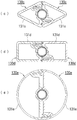
- a heating element cover 9 shown in FIG. 10 has a pair of shell members 91a and 91b having the same shape as each other.
- a contact portion 92a having a concave surface formed so as to be in close contact with the outer surface of the circulation pipe 90, which is a body, a protruding piece portion 93a, and a concave portion 94a are formed, and the shell member 91b has an outer surface of the circulation pipe 90.
- adheres to was formed, the protrusion piece part 93b, and the recessed part 94b are formed.
- the shell members 91a and 91b are configured such that the projecting piece portion 93a is fitted into the recess 94b and the projecting piece portion 93b is fitted into the recess 94a so that the flow pipe 90 is sandwiched between the contact portions 92a and 92b. , 91b are fitted together.
- the heating element cover 9 has a simple structure that protects the flow pipe 90 by being provided with the above-described configuration and can be assembled only by fitting, a special tool or special technique is not required for the operation. Quick assembly is possible. Further, since the shell members 91a and 91b are the same parts, waste of parts procurement can be omitted, and as a result, the manufacturing cost can be reduced.
- the heating element cover 9 actually has an inner diameter formed by the abutting portions 92a and 92b slightly larger than the outer diameter of the flow pipe 90, and the gap formed is applied or filled with heat radiation grease. It was. Since both the contact portions 92a and 92b and the flow tube 90 need high processing accuracy in order to bring them into close contact with each other so that the flow tube 90 is not damaged by the pressing force applied from the contact portions 92a and 92b. It is.
- the surface of the flow pipe 90 is required to be cleaned and then applied, etc., which requires time and effort. Also, the heat dissipating grease applied may deteriorate and the conduction characteristics may deteriorate. .
- the present invention was devised in view of the above points, and protects the heating element of the radiant type air conditioner and has good adhesion to the heating element arranged therein, and excellent heat conductivity. It is an object of the present invention to provide a cover component, a heating element cover using the same, a radiant air conditioner, and an air conditioning system.
- the heating element cover component of the present invention has the required rigidity and thermal conductivity, and has the same length as the hollow outer shell portion and the required portion outside the outer shell portion. It is formed with a required thickness parallel to the longitudinal direction of the outer shell, has flexibility and thermal conductivity, and has a slit that penetrates in the thickness direction and is formed over the entire length parallel to the longitudinal direction.
- a split tube-shaped contact portion a connection portion that has flexibility and thermal conductivity, and that connects edges on both sides parallel to the longitudinal direction of the contact portion to the outer shell portion, and a width of the contact portion
- an engaging portion that is configured by an engaging element that is disposed at a line-symmetrical position having a longitudinal straight line located in the middle of the direction as a symmetry axis and that can be engaged with each other.
- the outer shell portion has a required rigidity to ensure the strength that the heating element cover component is not easily deformed. Further, since the outer shell portion has thermal conductivity, it can radiate heat conducted from the covering heating element and absorb heat from the outside (hereinafter collectively referred to as “heat exchange”). Further, since the outer shell portion is hollow, the weight of the member is reduced, and the load applied to the covering heating element is reduced.
- the abutting portion has thermal conductivity, so that heat can be exchanged between the heating element and the outer shell portion by contacting with the heating element to be covered.
- the abutting portion is flexible and has a substantially half-divided tube shape in which a slit penetrating in the thickness direction is formed over the entire length in parallel with the longitudinal direction, so that the covering heating element is sandwiched
- the heating element can be included so as to bend in the direction in which the width of the slit expands and no gap is formed between the heating element and the contact portion.
- the connecting portion has thermal conductivity, and by connecting the contact portion and the outer shell portion, heat moves between the heating element and the outer shell portion via the contact portion. Further, since the connecting portion is flexible, the connecting portion bends following the movement of the contact portion expanding, so that the movement of the contact portion expanding according to the thickness of the heating element is assisted. .
- the engaging portion has the above-described arrangement of the engaging elements so that the mating portions face each other with other heating element cover parts of the same structure and engage the paired engaging elements. With this, the heating element cover can be assembled.
- the slit is formed in a shape that gradually narrows from the hollow region side in the outer shell portion toward the outer surface of the contact portion, the thickness of the contact portion is reduced as a whole. Instead, by forming a thin part only in the periphery of the slit, the contact portion is bent and the contact portion is easily expanded in the direction in which the contact portion swells.
- the heating element cover part is manufactured by extrusion processing
- the slit forming part of the extrusion die used is a thin streak, the part tends to be chipped by pressurization, and the durability of the extrusion die
- the slit forming portion of the extrusion die can be made large, while the width of the slit appearing on the outer surface side of the contact portion does not have to be widened.
- the outer shell portion, the contact portion, the connection portion, and the engagement portion are made of aluminum or aluminum alloy, and the outer shell portion, the contact portion, the connection portion, and the engagement portion are outside the same.
- the corrosion resistance is improved by the formed film.
- the coating formed on the inner surface of the outer shell can improve resistance to corrosion caused by temperature changes and condensation occurring in the hollow region of the outer shell.
- the film formed on the outer surface such as the outer shell can improve the heat dissipation and increase the efficiency of heat exchange.
- the alumite film formed on the abutting portion has an insulating property, it does not pass electricity, and this may cause electric corrosion that may occur when the heating element to be attached is a dissimilar metal such as copper ( Prevents the occurrence of galvanic corrosion.
- one of the engaging elements is a protruding piece that protrudes in a direction opposite to the outer shell and is formed with a locking claw, and the other of the engaging elements is set to a size that can receive the protruding piece.
- the protruding piece insertion portion is capable of locking the locking claw
- the protruding piece of one heating element cover component is inserted into the protruding piece insertion portion of the other heating element cover component to engage the locking claw.
- the protruding piece of the other heating element cover part is fitted into the protruding piece insertion portion of the one heating element cover part, and the locking claw is locked.
- Each heating element cover component can be firmly fixed by simply fitting the mating portions facing each other.
- the engagement element is a simple structure that only fits the protruding piece and the protruding piece insertion portion, no special tools or special techniques are required for the assembly work to the covering heating element. Quick assembly is possible.
- the heating element cover according to the present invention has the required rigidity and thermal conductivity, and has a hollow outer shell portion having a required length and the outer portion of the outer shell portion. It is formed with a required thickness parallel to the longitudinal direction of the shell, has flexibility and thermal conductivity, and has a slit that penetrates in the thickness direction over the entire length parallel to the longitudinal direction.
- a pair of heating element cover parts having an engaging portion that is formed by an engaging element that is disposed in a line-symmetrical position with a longitudinal straight line positioned in the middle as an axis of symmetry and that can be engaged with each other;
- the engagement elements that are paired with each other face each other so that the contact portions are aligned with each other.
- the outer shell portion has a required rigidity to ensure a strength that does not easily deform. And it prevents that the heat generating body to cover deform
- the abutting portion has thermal conductivity, so that heat can be exchanged between the heating element and the outer shell portion by contacting with the heating element to be covered.
- the abutting portion is flexible and has a substantially half-divided tube shape in which a slit penetrating in the thickness direction is formed over the entire length in parallel with the longitudinal direction, so that the covering heating element is sandwiched
- the heating element can be included so as to bend in the direction in which the width of the slit expands and no gap is formed between the heating element and the contact portion.
- the connecting portion has thermal conductivity, and by connecting the contact portion and the outer shell portion, heat moves between the heating element and the outer shell portion via the contact portion. Furthermore, since the connection portion has flexibility, the connection portion bends following the movement of the contact portion expanding, and assists the movement of the contact portion expanding according to the thickness of the heating element.
- the engaging portion has the above-described arrangement of the engaging elements so that the mating portions face each other with other heating element cover parts of the same structure and engage the paired engaging elements. With this, the heating element cover can be assembled.
- each heating element cover part described above is engaged with each other so that the engaging elements that are paired with each other face each other so that the abutting portions are aligned with each other. Obtainable.
- the engagement elements are in the above-described line-symmetrical positions, so that both ends of the contact portions are also combined. Just fit.
- the contact portion and the heat generating body are in close contact with each other, and no gap is formed between the heat generating body in the contact portion, so that the thermal conductivity and the heat exchange efficiency are improved. Furthermore, even if the diameter of the combined abutment portion is slightly smaller than that of the heating element, each abutment portion is bent and deformed so that the abutting portion and the heating element are in close contact with each other. In order to achieve this, high processing accuracy is required, but the above-described configuration allows attachment even if there is some error.
- the pair of heating element covers constituting the heating element cover are the same parts, waste of parts procurement can be eliminated, and the manufacturing cost can be reduced.
- a radiant air conditioner according to the present invention is disposed in a region between a support frame and a region sandwiched by or surrounded by the support frame, and the inside is a fluid heat medium.
- a hollow outer shell portion is formed at a required location outside the outer shell portion with a required thickness parallel to the longitudinal direction of the outer shell portion, and has flexibility and thermal conductivity.
- a connecting part that connects the edges on both sides to the outer shell part, and the width direction of the abutting part A pair of heating element cover parts having an engaging portion formed by engaging elements that are arranged in a line-symmetrical position with a longitudinal straight line positioned between them and that can be engaged with each other,
- a heating element cover having a structure in which the contact portions are opposed to each other, each tubular portion of the heating element is sandwiched, and the engagement elements that are paired with each other are opposed to each other and the engagement elements are engaged with each other.
- the support frame supports the heating element and the heating element cover with a predetermined interval. Moreover, a heat generating body transfers a heat
- the outer shell of the heating element cover has the required rigidity to ensure that it does not easily deform and prevents the heating element from being deformed or damaged by pressure or impact from the outside. Further, the outer shell portion has heat conductivity, so that heat conducted from the heating element can be radiated to the surroundings to exchange heat. As a result, the surface area can be made wider than in the case where the heating element is directly exposed, and the heat dissipation and heat absorption are improved, resulting in good heat exchange efficiency. Furthermore, since the outer shell is hollow, the weight of the member is reduced, and the load applied to the heating element and the support frame is reduced.
- the contact part of the heating element cover has thermal conductivity, so that heat can be exchanged between the contacting heating element and the outer shell part.
- the abutting portion has flexibility, and a slit that penetrates in the thickness direction is formed in a substantially half-divided tube shape that is formed over the entire length in parallel with the longitudinal direction, so when the heating element is sandwiched, Even if the thickness of the tubular portion of the heating element is slightly larger than the contact portion, the slit can be bent so that the width of the slit expands, so that no gap is generated between the heating element and the contact portion. .
- connection part of the heating element cover has thermal conductivity, and heat is transferred between the heating element and the outer shell part via the contact part by connecting the contact part and the outer shell part. Furthermore, since the connection portion has flexibility, the connection portion bends following the movement of the contact portion expanding, and assists the movement of the contact portion expanding according to the thickness of the heating element.
- the engaging element of the heating element cover has the above-described arrangement of the engaging elements, the mating parts of the heating element cover and the other heating element cover parts of the same structure face each other, and the pair of engaging elements are arranged.
- the heating element cover can be assembled by engaging.
- the radiation type air conditioner is configured to engage each of the above-described heating element cover parts with each other so that the engagement elements that are paired with each other face each other so that the contact portions are aligned with each other.
- the cover can be assembled.
- the engagement elements are in the above-described line-symmetrical positions, so that both ends of the contact portions are also combined. Just fit.
- the contact portion and the heat generating body are in close contact with each other, and no gap is formed between the heat generating body in the contact portion, so that the thermal conductivity and the heat exchange efficiency are improved. Furthermore, even if the diameter of the combined abutment portion is slightly smaller than that of the heating element, each abutment portion is bent and deformed so that the abutting portion and the heating element are in close contact with each other. In order to achieve this, high processing accuracy is required, but the above-described configuration allows attachment even if there is some error.
- the pair of heating element covers constituting the heating element cover are the same parts, waste of parts procurement can be eliminated, and the manufacturing cost can be reduced.
- Radiant air conditioners do not feel uncomfortable drafts when they are in operation, and the air heated or cooled by the heating element cover directly heats or cools the front space and convects the installation space. Because of this, the installation space can be efficiently heated or cooled.
- an air conditioning system of the present invention is disposed in a region between a support frame and a region sandwiched by or surrounded by the support frame, and allows refrigerant to flow therethrough.
- a heating element composed of a plurality of tubular parts spanned at intervals, and installed in each of the tubular parts of the heating element, having a required rigidity and thermal conductivity, and having a required length and a hollow
- the outer shell and a required portion outside the outer shell are formed with a required thickness parallel to the longitudinal direction of the outer shell, have flexibility and thermal conductivity, and penetrate in the thickness direction.
- a pair of heating element cover parts having an engaging portion formed by engaging elements that are arranged in a line-symmetrical position with a longitudinal straight line as a symmetry axis and that can be engaged with each other.
- a heating element cover having a structure in which contact portions are opposed to each other to sandwich each tubular portion of the heating element, and the engagement elements that are paired with each other are opposed to each other and the engagement elements are engaged with each other;
- a refrigeration cycle that is operated in combination with a radiant air conditioner and the radiant air conditioner, and that connects a compressor, an expansion valve, a flow path switching valve, an indoor heat exchanger, and an outdoor heat exchanger, and circulates a refrigerant.
- the radiant air conditioner is incorporated in the refrigerant circuit, and includes an air conditioner that supplies the air heat-exchanged with the refrigerant in the indoor heat exchanger into the room by a fan.
- the support frame of the radiation type air conditioner supports the heating element and the heating element cover with a predetermined interval. Moreover, the heat generating body of the radiant air conditioner transfers heat to the heat generating body cover that is in contact with the tubular portion, as the refrigerant supplied from the air conditioner circulates inside.
- the outer shell of the heating element cover has the required rigidity to ensure that it does not easily deform and prevents the heating element from being deformed or damaged by pressure or impact from the outside. Further, the outer shell portion has heat conductivity, so that heat conducted from the heating element can be radiated to the surroundings to exchange heat. As a result, the surface area can be made wider than in the case where the heating element is directly exposed, and the heat dissipation and heat absorption are improved, resulting in good heat exchange efficiency. Furthermore, since the outer shell is hollow, the weight of the member is reduced, and the load applied to the heating element and the support frame is reduced.
- the contact part of the heating element cover has thermal conductivity, so that heat can be exchanged between the contacting heating element and the outer shell part.
- the abutting portion has flexibility, and a slit that penetrates in the thickness direction is formed in a substantially half-divided tube shape that is formed over the entire length in parallel with the longitudinal direction, so when the heating element is sandwiched, Even if the thickness of the tubular portion of the heating element is slightly larger than the contact portion, the slit can be bent so that the width of the slit expands, so that no gap is generated between the heating element and the contact portion. .
- connection part of the heating element cover has thermal conductivity, and heat is transferred between the heating element and the outer shell part via the contact part by connecting the contact part and the outer shell part. Furthermore, since the connection portion has flexibility, the connection portion bends following the movement of the contact portion expanding, and assists the movement of the contact portion expanding according to the thickness of the heating element.
- the engaging element of the heating element cover has the above-described arrangement of the engaging elements, the mating parts of the heating element cover and the other heating element cover parts of the same structure face each other, and the pair of engaging elements are arranged.
- the heating element cover can be assembled by engaging.
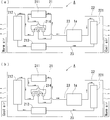
- the air conditioner includes a refrigerant circuit that performs a refrigeration cycle by connecting a compressor, an expansion valve, a flow path switching valve, an indoor heat exchanger, and an outdoor heat exchanger to circulate the refrigerant, and the refrigerant in the indoor heat exchanger
- a refrigerant circuit that performs a refrigeration cycle by connecting a compressor, an expansion valve, a flow path switching valve, an indoor heat exchanger, and an outdoor heat exchanger to circulate the refrigerant, and the refrigerant in the indoor heat exchanger
- the radiation type air conditioner is configured to engage each of the above-described heating element cover parts with each other so that the engagement elements that are paired with each other face each other so that the contact portions are aligned with each other.
- the cover can be assembled.
- the engagement elements are in the above-described line-symmetrical positions, so that both ends of the contact portions are also combined. Just fit.
- the contact portion and the heat generating body are in close contact with each other, and no gap is formed between the heat generating body in the contact portion, so that the thermal conductivity and the heat exchange efficiency are improved. Furthermore, even if the diameter of the combined abutment portion is slightly smaller than that of the heating element, each abutment portion is bent and deformed so that the abutting portion and the heating element are in close contact with each other. In order to achieve this, high processing accuracy is required, but the above-described configuration allows attachment even if there is some error.
- the pair of heating element covers constituting the heating element cover are the same parts, waste of parts procurement can be eliminated, and the manufacturing cost can be reduced.
- the radiant air conditioner is built into the refrigerant circuit of the air conditioner, so the refrigerant is supplied from the air conditioner side, so no equipment such as a compressor is required for the radiant air conditioner. It is also possible to perform such control.
- the radiant air conditioner does not feel an uncomfortable drafting feeling during operation, and the air heated or cooled by the heating element cover directly heats or cools the front space, Since convection occurs inside, the installation space can be efficiently heated or cooled.
- the above-mentioned air conditioning system can be brought close to the target temperature in a short time by operating mainly with an air conditioner at the start-up by operating in combination with a radiation type air conditioner and air conditioner, and then mainly using a radiation type air conditioner.
- the temperature in the installation space can be maintained, the fan operating time of the indoor heat exchanger can be kept short, and air conditioning that does not give an unpleasant draft to the human body is possible.
- the radiant heat from the radiant air conditioner directly affects the sensation of people nearby, and the air conditioner performs overall air conditioning. Rather than driving alone, it can shorten the time until comfort is obtained for those around. Furthermore, the temperature in the installation space can be equalized quickly by convection of the radiant heat from the radiant air conditioner and the air blown from the fan.
- the heating element cover component it is possible to provide a component that protects the heating element of the radiant air conditioner, has good adhesion to the heating element arranged inside, and has excellent thermal conductivity.
- the heat generating body cover by this invention while protecting the heat generating body of a radiation type
- the radiation type air conditioner according to the present invention it is possible to protect the heat generating element, provide good adhesion with the heat generating element disposed therein, and provide excellent heat conductivity.
- the heating element of the radiant air conditioner incorporated in the air conditioning system is protected, and the adhesiveness with the heating element arranged inside is good and the heat conductivity is excellent. can do.
- FIG. 1 is a front view of the radiant type air conditioner which comprises the air conditioning system shown in FIG. 1
- FIG. 2 is AA sectional drawing of the radiant type air conditioner shown in FIG. 2 (a).
- FIG. 3 shows the front and rear of the heating element cover using the heating element cover component shown in FIG.
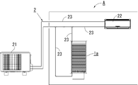
- the air conditioning system A shown in FIGS. 1 and 6 includes a radiant air conditioner 1a, an air conditioner 2 including an outdoor unit 21 and a convection type indoor unit 22, and each part will be described below.
- the radiant air conditioner 1 a includes a support frame 11, a heating element 12, a heating element cover 13, a reflecting plate 15, a water receiver 16, and a panel body 17.
- the support frame 11 has a support portion 110 that is erected with respect to the installation surface F (a floor surface or the like if indoors) of the radiation type air conditioner 1a and is arranged with a space in the horizontal direction.
- Each support portion 110 is housed inside so that connection portions located at both ends of the heating element 12 to be described later cannot be seen from the outside (see FIG. 2A).
- the heating element 12 is a copper tube through which refrigerant can flow, and is disposed in a region between the support portions 110 of the support frame 11.
- the heating element 12 has a structure in which the heating element 12 is meandered in the vertical direction so as to be along the same plane in the vertical direction so as to be connected at both ends, and the heating element cover 13 is attached to each horizontal portion arranged at regular intervals.
- a connection portion 181 is provided above the radiation type air conditioner 1a, and a connection portion 182 is provided below the connection portion, and these are connection portions to the refrigerant injection pipe or the return pipe.
- Each horizontal portion of the heating element 12 has an outer diameter of a circular area in a cross section formed by the contact portion 134a and the contact portion 134b when the heat generating body cover parts 130a and 130b are fitted. It is substantially the same as the inner diameter or slightly larger in diameter. More specifically, when the numerical value of the inner diameter of the circular region constituted by the contact part 134a and the contact part 134b is 100, the numerical value of the outer diameter of each horizontal portion of the heating element 12 is 105.
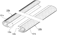
- Heating element cover 13 Please refer to FIG. 3, FIG. 4 and FIG.
- the heating element cover 13 has a structure that covers the heating element 12 and can radiate heat conducted from the heating element 12 to the outside.
- the heating element cover 13 having a required length is configured by a combination of a pair of heating element cover parts 130a and 130b having the same shape. When the heating element cover parts 130a and 130b are fitted together, the outer shape of the cross section becomes a slightly flat and substantially elliptical shape (see FIG. 5B).
- Each heating element cover 13 is attached to the support frame 11 so that the major axis direction of the cross section is inclined downward toward the reflecting plate 15 (see FIG. 2B).
- the inclination angle when each heating element cover 13 is attached to the support frame 11 is 45 °, where the angle at which the major axis of the elliptical cross section of the heating element cover 13 is horizontal is 0 °.
- the heating element cover parts 130a and 130b are made of an aluminum alloy having the required rigidity and thermal conductivity, and are manufactured by extrusion and cut to a necessary length for use. Since the heating element cover parts 130a and 130b have the same structure, the heating element cover part 130a will be described below as an example.
- the heat generating body cover component 130a has a slightly flat, substantially semi-elliptical shape with a cross-sectional outer shape divided in the minor axis direction in an end view, and includes an outer shell portion 131a and a mating portion 133a.
- An outer surface of the outer shell 131a and the mating portion 133a and an inner surface of the outer shell 131a are anodized.
- the outer shell 131a has a space 132 continuous in the longitudinal direction on the inner side.
- the outer shell 131a is subjected to knurling that is uneven in the longitudinal direction on the inner wall of the space 132 excluding the entire outer surface and the back side of the abutting portion 134a.
- the outer shell portion 131a is slightly thin so that the vicinity of a protruding piece insertion portion 140a, which will be described later, is flexible, but the other portions are formed with a thickness that can ensure the required rigidity.
- the mating part 133a includes an abutting part 134a provided with a slit 135a, a connecting part 136, and an engaging part having a protruding piece 138a and a protruding piece fitting part 140a as engaging elements.
- the abutting part 134a has a substantially half-divided tube shape and is semicircular when viewed from the end.
- the contact part 134a is provided in a required location outside the outer shell part 131a in parallel to the longitudinal direction, and the edges 136 on both sides parallel to the longitudinal direction are formed by a connecting part 136 formed with a flexible wall thickness.
- the outer shell 131a is connected.
- the abutting portion 134 a has a slit 135 a that extends in the middle of the arc direction in the thickness direction, is provided over the entire length in parallel with the longitudinal direction, and is connected to the space 132.
- the slit 135a is formed in a shape (substantially wedge-shaped in cross section) that gradually narrows from the space 132 side, which is the outer peripheral side, toward the inner peripheral side of the contact portion 134a.
- the slit 135a is formed on the inner peripheral surface side of the contact portion 134a (the side in contact with the heating element 12) so as to appear with a width of about 0.5 to 1 mm.
- the protruding piece 138a and the protruding piece insertion portion 140a are arranged at line-symmetrical positions with a longitudinal straight line located in the middle of the contact portion 134a in the width direction as a symmetrical axis (a point positioned at the center of the broken line in FIG. 4). It forms a pair of engageable structures.
- the protruding piece 138a protrudes from one connecting portion 136 to the opposite side to the outer shell portion 131a, and a locking claw 139a is provided in the vicinity of the tip.
- the protruding piece insertion portion 140a has an internal space of a size that can receive the protruding piece 138a, and a locking claw fastening portion 141a that is a convex portion that can lock the locking claw is provided on the inner wall of the internal space. ing.
- the locking claw fastening portion 141a is for locking the locking claw 139b of the heating element cover component 130b to be combined.
- each part of the heating element cover component 130b is the same as that of the heating element cover component 130a, so that individual explanation is omitted, but the outer shell part 131b is 131a, the mating part 133b is 133a, The contact part 134b is 134a, the slit 135b is 135a, the protruding piece 138b is 138a, the locking claw 139b is 139a, the protruding piece insertion part 140b is 140a, and the locking claw fastening part 141b is 141a. It has a similar structure.
- the reflection plate 15 is formed of a heat insulating material and has a non-water-permeable reflection surface 151, and the reflection surface 151 is spaced from the lower edge portion in the major axis direction of the heating element cover 13. They are arranged so as to face each other.
- a guide plate 152 bent at an obtuse angle toward the heating element cover 13 is attached to the lower end of the reflecting plate 15. The front end of the guide plate 152 is positioned inside a water receiving portion 16 to be described later.
- the water receiver 16 is disposed below the lowermost heating element cover 13 and below the reflecting plate 15 (more specifically, below the guide plate 152 attached to the reflecting plate 15). It is in the shape of a reed with an upper opening.
- the panel body 17 is made of punching metal, and is attached to the lower front side of the radiant air conditioner 1a.
- the panel body 17 covers the water receiving portion 16 and the piping portion (not shown) so as to be blinded when viewed from the front. Further, the panel body 17 is attached so that a gap for ventilation is formed between the panel body 17 and the installation surface F.
- the air conditioner 2 is configured such that a connected outdoor unit 21 and a general convection indoor unit 22 are connected by a refrigerant pipe 23.
- the path between the outdoor unit 21 and the convection type indoor unit 22 is connected to and communicated with the radiant air conditioner 1a in series.
- the radiant air conditioner 1a and the convection type indoor unit 22 installed in a room or the like having an air conditioning target area form part of the refrigerant circuit, and the refrigerant is circulated through the refrigerant circuit, whereby the air conditioning target. It is possible to perform cooling operation or heating operation in the area.
- the outdoor unit 21 has a known structure including a compressor 211, an outdoor heat exchanger 212, an expansion valve 213, and a four-way switching valve 214, and the convection type indoor unit 22
- This is a known structure including a heat exchanger 221 and a blower fan (not shown).
- blower-type air conditioner constitute what is called a blower-type air conditioner.
- air conditioners in the description of the operation, they may be simply referred to as “air conditioners”.
- the indoor heat exchanger 221 functions as an evaporator during cooling operation, and functions as a condenser (heat radiator) during heating operation, and performs heat exchange between air supplied from a blower fan or the like and refrigerant, and is subject to air conditioning. Create heating air or cooling air to supply to the area.
- the above-described devices are connected by the refrigerant pipe 23 and constitute a part of the refrigeration cycle (refrigerant circuit) of the air conditioning system A.
- FIGS. Assembly method of heating element cover 13
- the mating portions 133a and 133b of the heating element cover parts 130a and 130b face each other
- the protruding piece 138a is a protruding piece insertion portion 140b
- the protruding piece 138b is a protruding piece insertion portion 140a
- the heating elements 12 are arranged so as to face each other and are sandwiched between the contact portions 134a and 134b. At this time, the slits 135a and 135b have not been expanded yet.
- the heating element cover parts 130a and 130b are fitted.
- the outer shape of the horizontal cross section of the horizontal portion of the heating element 12 is slightly larger than the inner diameter of the circular region constituted by the abutting portions 134a and 134b, the heating element 12 is brought into contact with the abutting portions 134a (134b). ), A force applied in the direction of P1 is generated (note that a partly enlarged view of the contact part 134b is omitted, but the same action as that of the partly enlarged view of the contact part 134a is performed. Has occurred).
- the contact portion 134a (134b) is bent by the force applied in the direction P1, expands in the directions P2 and P3, and forces are also applied in the directions P4 to P7, so that the connection portion 136 and the outer shell portion 131a (131b) Some also bend. Accordingly, the heating element cover parts 130a and 130b can be attached to the horizontal portion of the heating element 12, and after the attachment, the heating element 12 and the heating element cover parts 130a and 130b are in close contact with each other and are held so as not to move. .
- the heating element cover 13 attached in this way is combined with the heating element cover parts 130a and 130b, the protruding piece 138a and the protruding piece insertion portion 140b, which are engaging elements, and the protruding piece 138b and the protruding piece insertion portion 140a are described above. Since the both ends of the contact portions 134a and 134b in the arc shape (semicircle shape) are also combined, it can be fitted into the circular heating element 12 exactly.
- the slits 135a and 135b are formed in a substantially wedge shape in the cross section as described above, the slits 135a and 135b are partially thinned only around the slits without reducing the thickness of the contact portions 134a and 134b as a whole, The contact portions 134a and 134b are bent with the slit portion as a trigger, and the contact portions are easily expanded in the direction of swelling.
- the contact portions 134a and 134b and the heating element 12 are in close contact with each other, and no gap is formed between the contact portions 134a and 134b and the heating element 12, so that thermal conductivity and heat exchange efficiency are improved. Furthermore, the contact portions 134a and 134b are configured so that each contact portion can be bent and deformed even if the diameter thereof is slightly smaller than that of the heating element 12, so that the contact portions and the heating element are conventionally provided. Although high processing accuracy is required to adhere the two, due to the above-described configuration, it can be attached even if there is some error.
- the alumite film formed on the abutting portions 134a and 134b has an insulating property and therefore does not conduct electricity, and prevents the occurrence of electric corrosion (galvanic corrosion) due to the difference between the materials of the abutting portion and the heating element.
- a corrosion protection film is formed at least on the contact portions 134a and 134b in view of preventing the occurrence of electrolytic corrosion.
- the heating element cover parts 130a (130b) which are constituent parts are the same, it is possible to eliminate wasteful parts procurement and to reduce the manufacturing cost. .
- the heating element cover 13 has the above-described structure and is simple enough to fit the heating element cover part 130a (130b), a special tool or special technique is required for the assembly work to the heating element 12. Therefore, quick assembly is possible.
- the heating element cover 13 radiates radiant heat to the outside. Radiant heat from the heating element cover 13 is directly radiated from the side disposed on the front side of the radiant air conditioner 1a to the front side of the radiant air conditioner 1a, and from the side disposed on the back side. The generated surface is reflected by the reflecting surface 151 of the reflecting plate 15 and is radiated to the front side of the radiant air conditioner 1a through the gaps between the heating element covers 13. In addition, since the mounting angle of the heating element cover 13 is 45 °, the radiant flux generated from the front side of the heating element cover 13 is easily directed to the front side and the front side floor surface of the radiant air conditioner 1a. Either radiant heat of cooling or heating can be directly applied to the person on the front side of the air conditioner 1a.
- the heating element cover 13 prevents the heating element 12 from being deformed or damaged by pressure or impact from the outside.
- the surface area in which the radiant heat is generated is made wider and the heat exchange efficiency is improved than in the case where heat is radiated by the heating element 12 alone.
- the heat exchange efficiency is improved because the surface area is larger even when the heat is absorbed than when the heat generating element 12 absorbs heat alone. Note that the heat conduction path in the case of heat absorption is opposite to that in the case of the heat dissipation described above (from the outer shell portion toward the heating element).
- the heating element cover 13 is attached at an inclination, so that when condensed water is generated on the surface of the heating element cover 13 during the cooling operation, the condensed water flows only to the reflecting plate 15 side. . And the dew condensation water (illustration omitted) adhering to the reflective surface 151 flows down to the water receiving part 16 located below along a board surface. Furthermore, even if condensed water drops on the heating element cover 13 positioned below, the heating element cover 13 is inclined toward the reflecting plate 15 as described above, and therefore does not scatter to the front side of the radiant air conditioner 1a.
- the water receiving section 16 changes the convection direction to guide the cold air to flow toward the front side of the radiant air conditioner 1a, so that the cold air convection from the top to the bottom at the time of cooling directly hits the installation surface F. This prevents condensation on the installation surface F.
- the radiation type air conditioner 1a during operation, the air flow generated in the space in the installation area is not natural convection due to the temperature difference in the space, instead of the forced convection as in the conventional air conditioner. Therefore, the air heated or cooled by the heating element cover 13 directly warms or cools the space in front of the radiant air conditioner 1a without causing an uncomfortable draft feeling to be felt by those around. Since convection occurs in the installation space, the installation space can be efficiently heated or cooled. Moreover, the radiation type air conditioner 1a can prevent the surroundings of an installation location from being polluted with the generated dew condensation water.
- Air conditioning system A takes advantage of each of the radiant air conditioner and air conditioner (air conditioner: the space can be quickly brought to the target temperature by forced convection. Radiant air conditioner: does not give the user a draft feeling) It compensates for the shortcomings (air conditioner: gives the user a draft feeling. Radiant air conditioner: it takes time to reach the target temperature in the space).
- air conditioning system A when switching air conditioning, the air conditioning system A operates by reversing the distribution direction of a refrigerant
- the air-conditioning system A keeps the temperature in the space by operating the air conditioner 2 as a main body at first to approach the target temperature in a short time, and thereafter operating mainly the radiation type air conditioner 1a. Can do. Thereby, the fan operating time of the convection type indoor unit 22 can be kept short, and air conditioning that does not give an unpleasant draft to the human body is possible.
- the radiant heat from the radiant type air conditioner 1a directly affects the sensation of the person around, and the air conditioner 2 performs the entire air conditioning. Rather than operating alone, the radiation type air conditioner 1a requires a shorter time until comfort is obtained for those in the vicinity. Furthermore, by convection of the radiant heat from the radiation type air conditioner 1a and the air blow from the air conditioner 2, the temperature in the space can be made uniform in a short time.
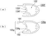
- a heating element cover component 130f shown in FIG. 7A is a modification of the slit of the heating element cover component.
- the slit 135f of the heating element cover component 130f is formed in a shape having a constant width straight from the space 132 side toward the inner peripheral side of the contact portion 134f.
- the contact area with the heat generating body 12 will reduce if the width
- the width of the slit is narrowed, the load applied to the slit forming portion of the extrusion mold is large, and the mold is likely to be damaged because the portion is thin and weak in strength.
- the width of the slit 135f may be narrowed by forming the slit width slightly wider like the heating element cover part 130f and pressing the heating element cover part 130f so as to be crushed in the minor axis direction.
- the slit 135f after the width is narrowed can be expanded to an appropriate size according to the size of the heating element 12, so that the contact area with the heating element 12 is not reduced excessively by the opening of the slit being too wide. be able to.
- a heating element cover component 130g shown in FIG. 7B is a modification of the engaging element of the engaging portion.
- the engaging element of the engaging portion 137g includes a guide piece 191 protruding in a bowl shape and a guide groove 192 having a shape that can be received by sliding the guide piece 191 from the end surface direction.
- the guide piece 191 and the guide groove 192 are arranged in a line-symmetric position with a longitudinal straight line located in the middle in the width direction of the contact portion 134g as a symmetry axis, and form a pair of structures that can be engaged with each other.
- heating element cover component 130g is different from the end portion side of one heating element cover component 130g except that the other heating element cover component 130g is attached while sliding. Since the configuration and operation of this part are the same as those of the above-described heating element cover part 130a (130b), description thereof will be omitted.
- FIG. 8C is a third modification
- FIG. 8D is a fourth modification
- FIG. 8E is a fifth modification, which is a modification of the outer shell portion of the heating element cover component.
- the heating element cover component 130c shown in the modified example 3 in FIG. 8C has a substantially triangular outer shape in cross section.
- a heating element cover component 130d shown in Modification 4 in FIG. 8D has a substantially quadrangular outer shape in cross section.
- a heating element cover component 130e shown in Modification 5 in FIG. 8E has a substantially semicircular outer shape in cross section.
- action of another part are as substantially the same as the above-mentioned heat generating body cover component 130a (130b), description is abbreviate
- the radiation type air conditioner 1b shown in FIG. 9 is a modification in which the direction in which the heating element and the heating element cover are arranged is the vertical direction.
- the heating element covers 13b enclosing the heating elements 12b are arranged so that their outer surfaces do not face each other so that the adjacent heating element covers 13b are not easily affected by radiant heat. It is arranged in the shape of a letter (or zigzag), and also in this respect, the heat exchange efficiency can be increased.
- the radiation type air conditioner 1a includes the reflector 15.
- the present invention is not limited to this.
- the reflector 15 is not provided, and the radiation type air conditioner 1a is disposed on the front side and the rear side. It is good also as what discharge
- the engaging element of the engaging portion is composed of a protruding piece having a locking claw and a protruding piece insertion portion having a locking claw fastening portion, but adopts other known engaging structures. Also good. Further, the engaging element may be provided in a separable mechanism. In this case, the heating element cover can be disassembled, and maintenance performance for cleaning and parts replacement is improved.
- the air conditioning system A has one outdoor unit 21, one convection type indoor unit 22, and one radiant type air conditioner 1a, but is limited to the number shown. It is not a thing.
- the slit 135a is formed in a shape (substantially wedge-shaped in cross section) that gradually narrows from the space 132 side that is the outer periphery side toward the inner periphery side of the contact portion 134a.
- the present invention is not limited to this.
- it may be straight as in Modification 1 described above.
- the slit can also be formed by post-processing such as cutting after forming a heating element cover part without a slit (other parts other than the slit are the same as those of the heating element cover part 130a).
- the heating element cover parts 130a and 130b have a substantially semi-elliptical shape with a slightly flat cross-sectional outer shape.
- the present invention is not limited to this, and for example, Modification 3 and Modification 4 described above.
- various shapes can be set as appropriate.
- the direction in which the heating element 12 and the heating element cover 13 are arranged is the horizontal direction, but is not limited to this, for example, the vertical direction as in the above-described modified example 6. Alternatively, it can be appropriately changed in various directions.
- the heating element 12 is a meandering pipe as described above, but is not limited to this, and for example, liquid can be passed between a pair of vertical pipes and the pipes. It may be a ladder having a plurality of tubular heat generating portions that are stretched over.
- connection part 181 and the connection part 182 of the heat generating body 12 are provided in the above-mentioned position, it is not limited to this, The position and number can be set suitably.
- the inclination angle when the heating element cover 13 is attached to the support frame 11 is 45 °, but is not limited to this, and may be within a range of 1 ° to 89 °, for example. Furthermore, the inclination angle of the above-described heating element cover 13 is preferably in the range of 35 ° to 70 °. If the inclination angle is in the range, the lower side of the heating element cover 13 will be described later. This is because the radiant flux generated from the side tends to be directed from the front side of the radiant air conditioner 1a to the front side floor surface.
- the inner and outer surfaces of the heating element cover parts 130a and 130b are knurled and anodized.
- the present invention is not limited to this.
- other types of heat radiation coating, far-infrared emission The heating element cover may be provided with various functions by applying one or a combination of coatings selected from coatings with anti-deodorant function, antibacterial function or adsorption / decomposition function of volatile organic compounds. it can.
- such processing does not exclude applying only to one of the above-described inner and outer surfaces.
- the heat dissipation of the heating element cover is improved by applying a heat dissipation coating, and if the farther infrared emission coating is applied to the heating element cover, the temperature of the room is adjusted by combining the emitted far infrared rays with the radiant heat. Is done efficiently. Furthermore, by applying a coating that has a deodorizing function, an antibacterial function, or a volatile organic compound adsorption / decomposition function to the heating element cover, the maintenance of the radiant air conditioner can be made easier and more comfortable to use. It becomes possible.
- a region of the outer surface (outer shell 131a, 131b) of the heating element cover 13 facing the reflecting plate 15 is subjected to a water repellent process or a process that easily causes condensed water to flow down, such as a guide groove.
- mold air conditioner 1a may be the aspect which gave the process which improves heat dissipation effects, such as a knurling process.
- the dew condensation water generated in the heating element cover 13 or the dew condensation water dropped from the heating element cover 13 located on the heating element cover 13 easily flows down to the reflecting plate 15 side, and is the front side of the radiation type air conditioner 1a. It is hard to go to.
- region which faced the reflecting plate 15 side is not excluded.
- the outer surface of the heating element cover 13 is knurled on the front side of the radiation type air conditioner 1a, the heat radiation efficiency to the person or space located on the front side is good.
- the abutting portions 134a and 134b are semicircular when viewed from the end, but are not limited thereto.
- the heating element is a triangular or square prismatic tube, It may be a square shape that can be sandwiched.
- the panel body 17 is attached to the lower front side of the radiation type air conditioner 1a, but is not limited to this, and a pipe part (not shown) or the like is provided at the upper part.
- the aspect attached to the front side upper direction of the radiation type air conditioner 1a may be sufficient.
- a refrigerant is used as the fluid heat medium, but is not limited to this.
- a liquid phase refrigerant such as carbon, a gas-liquid two phase refrigerant, and a gas phase refrigerant are exemplified, but the present invention is not limited to this, and other known fluid heat medium may be adopted.
- hot water or cold water handling is easier than in the case where the fluid heat medium is oil or a chemical substance, and the environmental load can be suppressed during disposal.
- the radiant air conditioner 1a uses a refrigerant common to the refrigerant circuit of the air conditioner 2 as a fluid heat medium, but each may use a dedicated refrigerant, Different flowable heat media may be used.
- the numerical value of the outer diameter of each horizontal portion of the heating element 12 is set to 105.
- the present invention is not limited to this, and for example, the numerical value of the outer diameter of each horizontal portion of the heating element 12 is preferably in the range of 100 to 112.
- the numerical value of the outer diameter of each horizontal portion of the heating element 12 is 100 or less, a gap is generated between the heating element 12 and the contact portions 134a and 134b, and when the numerical value is 112 or more, the heating element cover 13 is short. This is because there is a large possibility that the outer peripheral portion where the heating element cover parts 130a and 130b come into contact with each other due to excessive expansion in the radial direction is opened or the heating element 12 is deformed.
- the heating element cover 13 has an outer diameter of each horizontal portion of the heating element 12 when the numerical value of the inner diameter of the circular region constituted by the abutting portions 134a and 134b is 100. Even if the numerical value of 99 is 99 or less, it can be mounted by using a heat transfer member such as heat radiation grease as in the conventional case, but for the reasons described above, the inner diameter of the circular region constituted by each contact portion However, it is preferable that the outer diameter of each horizontal portion of the heating element is the same or slightly larger.
- connection part 136 when the contact part 134a and the like expand in the direction in which the contact part 134a swells, the connection part 136 (particularly the connection part 136 on the side where the protruding piece insertion part 140a is formed) is also bent and deformed (
- the bending deformation location is, for example, around the portion where the outer shell portion 131a or the like and the connecting portion 136 are connected, or on the outer periphery of the outer shell portion 131a or the like. In some cases, it is around the middle (see FIG. 4).
- a air conditioning system F installation surface, 1a, 1b Radiation type air conditioner, 11 Support frame, 110 Support part, 12, 12b Heating element, 13, 13b Heating element cover, 130a, 130b, 130c, 130d, 130e, 130f, 130g Heating element cover part, 131a, 131b 131c, 131d, 131e outer shell part, 132 space, 133a, 133b, 133g mating part, 134a, 134b, 134f, 134g Contact part, 135a, 135b, 135f Slit, 136 Connection part, 138a, 138b Projection piece, 139a, 139b Locking claw, 140a, 140b Projection piece insertion part, 141a, 141b Locking claw clip 15 reflective plate, 151 reflective surface, 152 guide plate, 16 water receiving portion, 17 panel body, 181 and 182 connecting portion, 191 guide piece, 192 guide groove, 2 air conditioner, 21 outdoor unit, 211 compressor, 212 outdoor heat exchanger, 213 expansion valve,
Landscapes
- Engineering & Computer Science (AREA)
- Mechanical Engineering (AREA)
- Physics & Mathematics (AREA)
- General Engineering & Computer Science (AREA)
- Life Sciences & Earth Sciences (AREA)
- Thermal Sciences (AREA)
- Geometry (AREA)
- Sustainable Development (AREA)
- Chemical & Material Sciences (AREA)
- Combustion & Propulsion (AREA)
- Devices For Blowing Cold Air, Devices For Blowing Warm Air, And Means For Preventing Water Condensation In Air Conditioning Units (AREA)
- Resistance Heating (AREA)
- Air-Conditioning For Vehicles (AREA)
Abstract
Description
殻部材91a、91bは、流通管90を当接部92a、92bで挟むようにして、凹部94bに突出片部93aを嵌入させると共に、凹部94aに突出片部93bを嵌入させることによって、各殻部材91a、91bを相互に嵌め合わせる構造である。
発熱体カバー9は、前述の構成を備えることによって、流通管90を保護すると共に、嵌め合わせるだけで組み立て可能な簡易な構造であるため、作業にあたって特殊な工具や特別な技術を必要とせず、手早い組み立てが可能となる。また、殻部材91a、91bが同一部品であるため、部品調達の無駄を省き、ひいては製造コスト低減を図ることができるものであった。
また、前記スリットが、前記外殻部内の中空の領域側から前記当接部の外表面方向に向かって徐々に狭まる形状に形成されたものである場合は、当接部の厚みを全体として減らすことなく、スリット周辺のみ部分的に薄く構成することにより、スリット部分をきっかけとして当接部が撓み、当接部が膨らむ方向に拡張しやすくなる。
また、前記係合要素の一方が、外殻部と反対の方向に突出し、係止爪が形成された突出片であり、前記係合要素の他方が、該突出片を受容可能なサイズに設定され、前記係止爪を係止可能な突出片嵌入部である場合は、一方の発熱体カバー部品の突出片が他方の発熱体カバー部品の突出片嵌入部へ嵌入して係止爪を係止し、同様に、他方の発熱体カバー部品の突出片が一方の発熱体カバー部品の突出片嵌入部へ嵌入して係止爪を係止することにより、一対の発熱体カバー部品の各々の合わせ部を向かい合わせて嵌合させるだけで、各発熱体カバー部品を強固に固着することができる。
前述の空気調和システムは、輻射式冷暖房機とエアコンを組み合わせて運転することにより、始動時にエアコンを主体として運転することによって短時間で目的温度に近づけることができ、その後は輻射式冷暖房機を主体として運転することにより設置空間内の温度を保つことができ、室内熱交換器のファン作動時間を短く抑えて、人体に不快なドラフト感を与えない空調が可能となる。
本発明による発熱体カバーによれば、輻射式冷暖房機の発熱体を保護すると共に、内部に配置した発熱体との密着性が良く、熱伝導性に優れるものを提供することができる。
本発明による輻射式冷暖房機によれば、その発熱体を保護すると共に、内部に配置した発熱体との密着性が良く、熱伝導性に優れるものを提供することができる。
本発明による空気調和システムによれば、空気調和システムに組み込まれた輻射式冷暖房機の発熱体を保護すると共に、内部に配置した発熱体との密着性が良く、熱伝導性に優れるものを提供することができる。
図1ないし図9を参照して、本発明の実施の形態を更に詳細に説明する。なお、各図における符号は、煩雑さを軽減し理解を容易にする範囲内で付している。また、以下で述べる用語(発熱体の)「水平部分」は先に述べた「管状部分」と、用語(外殻部の)「空間」は先に述べた「外殻部内の中空の領域」と、それぞれ同等の意味で使用している。更に、以下で述べる「合わせ部」は、前述の「当接部」、「接続部」および「係合部」からなる箇所の総称の意味で使用している。
図2(a)、(b)を参照する。輻射式冷暖房機1aは、支持フレーム11と、発熱体12と、発熱体カバー13と、反射板15と、水受け部16と、パネル体17を有する。
支持フレーム11は、輻射式冷暖房機1aの設置面F(屋内であれば床面等)に対して立設され、水平方向に間隔を空けて配置される支持部110を有している。各支持部110は、後述する発熱体12の両端に位置する接続部分が外部から見えないように、内部に収納している(図2(a)参照)。
発熱体12は、内部を冷媒が流通可能な銅製の管体であり、支持フレーム11の支持部110の間の領域に配置されている。発熱体12は、両端側で繋ぐようにして、全体としては鉛直方向の同一平面に沿うように上下方向に蛇行した構造であり、一定間隔で並んだ各水平部分に発熱体カバー13が各々装着されている。輻射式冷暖房機1aの上方には、接続部181が、下方には接続部182がそれぞれ設けられ、これらは発熱体12へ流れる冷媒の注入管あるいは戻り管への接続部分である。
図3、図4、図5を参照する。発熱体カバー13は、発熱体12を覆い、かつ、発熱体12から伝導する熱を外部に放熱可能な構造である。所要の長さである発熱体カバー13は、互いに同じ形状である一対の発熱体カバー部品130a、130bの組み合わせにより構成される。発熱体カバー部品130a、130bを嵌め合わせると、横断面の外形が、やや扁平な略楕円形状となる(図5(b)参照)。
発熱体カバー部品130aは、横断面の外形が、端面視で短径方向に分割されたやや扁平な略半楕円形状であり、外殻部131aと合わせ部133aからなる。外殻部131aおよび合わせ部133aの外表面と、外殻部131aの内表面(後述する空間132の内壁)は、アルマイト加工が施されている。
なお、図4等において、発熱体カバー部品130bの各部構造は、発熱体カバー部品130aと同じであるため個別の説明は省略するが、外殻部131bは131aと、合わせ部133bは133aと、当接部134bは134aと、スリット135bは135aと、突出片138bは138aと、係止爪139bは139aと、突出片嵌入部140bは140aと、係止爪留め部141bは141aと、それぞれが対応しており、同様の構造を有している。
反射板15は、断熱材で形成されると共に、非透水性である反射面151を有し、反射面151が、発熱体カバー13の長軸方向において低い側の端縁部と間隔を空けて相対するように配置されている。反射板15の下端には、発熱体カバー13側へ鈍角に曲げられたガイド板152が取り付けられている。ガイド板152の先端は、後述する水受け部16の内部に位置するようにしてある。
(水受け部16)
水受け部16は、発熱体カバー13の中で最も下に位置するものの下方、かつ、反射板15の下(更に詳しくは、反射板15に取り付けられたガイド板152の下)に配置され、上方が開口した横樋状のものである。
パネル体17は、パンチングメタルで形成されており、輻射式冷暖房機1aの正面側下方へ取り付けられている。パネル体17は、水受け部16や配管部(図示省略)等について、正面方向から見た際の目隠しとなるように覆うものである。また、パネル体17は、設置面Fとの間に、通気のための隙間が形成されるように取り付けられている。
図1に示すように、エアコン2は、接続された室外機21と一般的な対流型室内機22が、冷媒配管23により接続されたものである。室外機21と対流型室内機22の間の経路には、輻射式冷暖房機1aが直列に接続されて連絡している。従って、空気調和対象域を有する部屋等に設置された輻射式冷暖房機1aと対流型室内機22は、冷媒回路の一部を形成し、この冷媒回路に冷媒を循環させることによって、空気調和対象域において冷房運転または暖房運転することが可能になっている。
図1から図6を参照して、空気調和システムAの作用を説明する。
(発熱体カバー13の組み立て方法)
図5を参照する。図5(a)に示すように、発熱体カバー部品130a、130bの合わせ部133a、133bを向かい合わせると共に、突出片138aが突出片嵌入部140bと、突出片138bが突出片嵌入部140aと、各々正対するようにし、発熱体12を当接部134a、134bの間に挟むように配置する。このとき、まだスリット135a、135bは拡張していない。
また、スリット135a、135bは、前述の通り横断面で略楔形に形成されたものであるので、当接部134a、134bの厚みを全体として減らすことなく、スリット周辺のみ部分的に薄く構成され、スリット部分をきっかけとして当接部134a、134bが撓んで各当接部が膨らむ方向に拡張しやすくなる。
(輻射式冷暖房機1aの作用)
エアコン2側から輻射式冷暖房機1aへ冷媒が流入すると、発熱体12内を冷媒が流通する。そして、発熱体12から当接部134aと134bへ冷媒の熱が伝導し、次いで、接続部136を介して外殻部131a、131bへ熱が伝導する。更に、当接部134aと134bからの輻射熱が、空間132も通って外殻部131a、131bに伝導する。
このようにして、発熱体カバー13は外部へ輻射熱を放射する。発熱体カバー13からの輻射熱は、輻射式冷暖房機1aの正面側に配置された側から生じる分は輻射式冷暖房機1aの正面方向側へ直接放射される共に、背面側に配置された側から生じる分は反射板15の反射面151が反射し、各発熱体カバー13の間の隙間を通じて、輻射式冷暖房機1aの正面方向側へ放射される。また、発熱体カバー13の取り付け角度は45°であるため、発熱体カバー13の正面側となる側から生じる放射束が、輻射式冷暖房機1aの正面側および正面側床面へ向いやすく、輻射式冷暖房機1aの正面側にいる者へ直接的に冷暖いずれかの輻射熱を与えることができる。
また、発熱体カバー13は、前述したように、傾斜して取り付けられていることによって、冷房運転時に発熱体カバー13表面に結露水が生じた場合、結露水は反射板15側にのみ流下する。そして、反射面151に付着した結露水(図示省略)は、板面を伝って下方に位置する水受け部16へ流れ落ちる。更に、結露水が下方に位置する発熱体カバー13へ滴下しても、前述の通り発熱体カバー13は反射板15側へ傾斜しているので、輻射式冷暖房機1aの正面側へ飛び散らない。
空気調和システムAは、輻射型冷暖房機とエアコンのそれぞれの長所(エアコン:強制対流によって早く空間内を目的温度にできる。輻射型冷暖房機:利用者にドラフト感を与えない)を生かし、それぞれの短所(エアコン:利用者にドラフト感を与える。輻射型冷暖房機:空間内を目的温度に到達させるのに時間が掛かる)を補うものである。なお、図6(a)と図6(b)に示すように、空気調和システムAは、冷暖房を切り換えるときは、冷媒の流通方向を逆転させて運転を行う。
〔変形例1〕
図7(a)に示す発熱体カバー部品130fは、発熱体カバー部品のスリットの変形例である。発熱体カバー部品130fのスリット135fは、空間132側から当接部134fの内周側の方向に向かって真っ直ぐ一定幅の形状に形成されたものである。
図7(b)に示す発熱体カバー部品130gは、係合部の係合要素の変形例である。この係合部137gの係合要素は、鉤状に突出したガイド片191と、このガイド片191を端面方向からスライドさせて収納できる形状のガイド溝192から構成される。ガイド片191とガイド溝192は、当接部134gの幅方向中間に位置する長手方向の直線を対称軸とする線対称位置に配置され、互いに係合可能な構造の対をなすものである。
図8を参照する。図8(c)は変形例3、図8(d)は変形例4、図8(e)は変形例5であって、発熱体カバー部品の外殻部の変形例である。図8(c)の変形例3に示す発熱体カバー部品130cは、横断面の外形が略三角形状である。図8(d)の変形例4に示す発熱体カバー部品130dは、横断面の外形が略四角形状である。図8(e)の変形例5に示す発熱体カバー部品130eは、横断面の外形が略半円形状である。なお、他の部分の構成および作用は、先述の発熱体カバー部品130a(130b)と概ね同様であるため、説明を省略する。
図9に示す輻射式冷暖房機1bは、発熱体と発熱体カバーが配置される向きが鉛直方向である変形例である。図9(b)で示すように、発熱体12bを内包する各発熱体カバー13bは、隣り合う各発熱体カバー13b同士で互いに輻射熱の影響を受けにくいように、外面が相対向しないようにハの字状(又はジグザグ状)に配置されており、この点でも熱交換効率を上げることができるようにしている。なお、他の部分の構成および作用は、先述の輻射式冷暖房機1aと概ね同様であるため、説明を省略する。
本実施の形態において、発熱体カバー部品130a、130bは、横断面の外形がやや扁平な略半楕円形状であるが、これに限定するものではなく、例えば、前述した変形例3、変形例4、変形例5のように、各種形状に適宜設定することができる。
本実施の形態において、発熱体カバー13を支持フレーム11に取り付ける際の傾斜角度は45°であるが、これに限定するものではなく、例えば、1°~89°の範囲内であればよい。更に、前述の発熱体カバー13の傾斜角度は、35°~70°の範囲内であることが好ましく、同傾斜角度の範囲であれば、後述するように、発熱体カバー13の下面側となる側から生じる放射束が、輻射式冷暖房機1aの正面側から正面側床面へ向いやすいためである。
より詳しくは、放熱用コーティングを施すことで、発熱体カバーの放熱性が向上し、また、発熱体カバーに遠赤外線放出用コーティングを施せば、放出される遠赤外線が輻射熱とも相まって室内の温度調節が効率的に行われる。更に、発熱体カバーに消臭機能、抗菌機能または揮発性有機化合物の吸着分解機能を有するコーティングを施すことで、これらの機能性によって輻射式冷暖房機のメンテナンスがより簡単になり、快適な使用が可能となる。
本実施の形態において、当接部134a等が膨らむ方向へ拡張する際には、接続部136(特に突出片嵌入部140aが形成された側の接続部136)もこれに伴って撓み変形する(変形の方向は図5(b)のP4~P7を参照)が、撓み変形する箇所は、例えば、外殻部131a等と接続部136が繋がった箇所あたりや、外殻部131a等の外周の中間あたり(図4参照)である場合もある。
1a、1b 輻射式冷暖房機、 11 支持フレーム、 110 支持部、 12、12b 発熱体、 13、13b 発熱体カバー、 130a、130b、130c、130d、130e、130f、130g 発熱体カバー部品、 131a、131b、131c、131d、131e 外殻部、 132 空間、 133a、133b、133g 合わせ部、
134a、134b、134f、134g 当接部、 135a、135b、135f スリット、 136 接続部、 138a、138b 突出片、 139a、139b 係止爪、 140a、140b 突出片嵌入部、 141a、141b 係止爪留め部、 15 反射板、 151 反射面、 152 ガイド板、 16 水受け部、 17 パネル体、 181、182 接続部、 191 ガイド片、 192 ガイド溝、
2 エアコン、 21 室外機、 211 圧縮機、 212 室外側熱交換器、 213 膨張弁、214 四方切換弁、22 対流型室内機、221 室内側熱交換器、23 冷媒配管、
9 発熱体カバー、90 流通管、91a、91b 殻部材、92a、92b 当接部、93a、93b 突出片部、94a、94b 凹部
Claims (7)
- 所要の剛性および熱伝導性を有し、所要長さで中空の外殻部と、
該外殻部の外側の所要箇所に同外殻部の長手方向と平行に所要厚さを以て形成されており、可撓性および熱伝導性を有し、厚み方向へ貫通するスリットが同長手方向と平行に全長にわたり形成された、略半割り管形状の当接部と、
可撓性および熱伝導性を有し、前記当接部の長手方向に平行な両側の縁を前記外殻部と繋ぐ接続部と、
前記当接部の幅方向中間に位置する長手方向の直線を対称軸とする線対称位置に配置されて互いに係合可能な構造の対をなす係合要素により構成される係合部とを備える
発熱体カバー部品。 - [規則91に基づく訂正 22.03.2016]
前記スリットが、前記外殻部内の中空の領域側から前記当接部の外表面方向に向かって徐々に狭まる形状に形成されたものである
請求項1に記載の発熱体カバー部品。 - 前記外殻部、前記当接部、前記接続部および前記係合部がアルミニウム製またはアルミニウム合金製であり、同外殻部、同当接部、同接続部および同係合部の外表面と、同外殻部の内表面にアルマイト加工が施されている
請求項1に記載の発熱体カバー部品。 - 前記係合要素の一方が、外殻部と反対の方向に突出し、係止爪が形成された突出片であり、前記係合要素の他方が、該突出片を受容可能なサイズに設定され、前記係止爪を係止可能な突出片嵌入部である
請求項1に記載の発熱体カバー部品。 - 所要の剛性および熱伝導性を有し、所要長さで中空の外殻部と、該外殻部の外側の所要箇所に同外殻部の長手方向と平行に所要厚さを以て形成されており、可撓性および熱伝導性を有し、厚み方向へ貫通するスリットが同長手方向と平行に全長にわたり形成された、略半割り管形状の当接部と、可撓性および熱伝導性を有し、前記当接部の長手方向に平行な両側の縁を前記外殻部と繋ぐ接続部と、前記当接部の幅方向中間に位置する長手方向の直線を対称軸とする線対称位置に配置されて互いに係合可能な構造の対をなす係合要素により構成される係合部とを有する発熱体カバー部品一対を、互いに対をなす前記係合要素同士を向かい合わせにして前記当接部同士を合わせるように同係合要素同士を係合させた構造である
発熱体カバー。 - 支持フレームと、
該支持フレームによって挟まれるか、または同支持フレームによって囲まれた間の領域に配置され、内部を流動性熱媒体が流通可能であり、間隔を空けて架け渡された複数の管状部分からなる発熱体と、
該発熱体の前記管状部分の各々に設置され、所要の剛性および熱伝導性を有し、所要長さで中空の外殻部と、該外殻部の外側の所要箇所に同外殻部の長手方向と平行に所要厚さを以て形成されており、可撓性および熱伝導性を有し、厚み方向へ貫通するスリットが同長手方向と平行に全長にわたり形成された、略半割り管形状の当接部と、可撓性および熱伝導性を有し、前記当接部の長手方向に平行な両側の縁を前記外殻部と繋ぐ接続部と、前記当接部の幅方向中間に位置する長手方向の直線を対称軸とする線対称位置に配置されて互いに係合可能な構造の対をなす係合要素により構成される係合部とを有する発熱体カバー部品一対を、前記当接部同士を互いに向かい合わせて前記発熱体の各管状部分を挟み込み、互いに対をなす前記係合要素同士を向かい合わせにして同係合要素同士を係合させた構造の発熱体カバーとを備える
輻射式冷暖房機。 - 支持フレームと、該支持フレームによって挟まれるか、または同支持フレームによって囲まれた間の領域に配置され、内部を冷媒が流通可能であり、間隔を空けて架け渡された複数の管状部分からなる発熱体と、該発熱体の前記管状部分の各々に設置され、所要の剛性および熱伝導性を有し、所要長さで中空の外殻部と、該外殻部の外側の所要箇所に同外殻部の長手方向と平行に所要厚さを以て形成されており、可撓性および熱伝導性を有し、厚み方向へ貫通するスリットが同長手方向と平行に全長にわたり形成された、略半割り管形状の当接部と、可撓性および熱伝導性を有し、前記当接部の長手方向に平行な両側の縁を前記外殻部と繋ぐ接続部と、前記当接部の幅方向中間に位置する長手方向の直線を対称軸とする線対称位置に配置されて互いに係合可能な構造の対をなす係合要素により構成される係合部とを有する発熱体カバー部品一対を、前記当接部同士を互いに向かい合わせて前記発熱体の各管状部分を挟み込み、互いに対をなす前記係合要素同士を向かい合わせにして同係合要素同士を係合させた構造の発熱体カバーとを有する輻射式冷暖房機と、
該輻射式冷暖房機と組み合わせて運転され、圧縮機、膨張弁、流路切替弁、室内側熱交換器および室外側熱交換器を配管接続し冷媒を循環させて冷凍サイクルを行う冷媒回路を含み、同輻射式冷暖房機が同冷媒回路に組み込まれていると共に、同室内側熱交換器で同冷媒と熱交換された空気をファンによって室内に供給するエアコンとを備える
空気調和システム。
Priority Applications (10)
| Application Number | Priority Date | Filing Date | Title |
|---|---|---|---|
| HK18103635.5A HK1244311B (en) | 2016-03-02 | 2016-03-02 | Heating element cover component, heating elelment cover, radiation cooling and heating equipment, and air-conditioning system |
| US15/022,964 US10066844B2 (en) | 2016-03-02 | 2016-03-02 | Heating element cover component, heating element cover, radiant cooling and heating apparatus, and air conditioning system |
| SG11201602334PA SG11201602334PA (en) | 2016-03-02 | 2016-03-02 | Heating element cover component, heating element cover, radiant cooling and heating apparatus, and air conditioning system |
| CN201680000096.9A CN107407486B (zh) | 2016-03-02 | 2016-03-02 | 发热体罩部件、发热体罩、辐射式制冷制热机以及空气调节系统 |
| MYPI2016700988A MY188054A (en) | 2016-03-02 | 2016-03-02 | Heating element cover component, heating element cover, radiant cooling and heating equipment, and air-conditioning system |
| EP16708921.8A EP3232128B1 (en) | 2016-03-02 | 2016-03-02 | Heating element cover component, heating elelment cover, radiation cooling and heating equipment, and air-conditioning system |
| CA2924556A CA2924556C (en) | 2016-03-02 | 2016-03-02 | Heating element cover component, heating element cover, radiant cooling and heating apparatus, and air conditioning system |
| PCT/JP2016/056366 WO2017149692A1 (ja) | 2016-03-02 | 2016-03-02 | 発熱体カバー部品、発熱体カバー、輻射式冷暖房機、および空気調和システム |
| TW105107909A TWI622740B (zh) | 2016-03-02 | 2016-03-15 | 發熱體遮罩零件、發熱體遮罩、輻射式冷暖氣機、以及空氣調節系統 |
| PH12016500539A PH12016500539A1 (en) | 2016-03-02 | 2016-03-21 | Heating element cover component, heating element cover, radiant cooling and heating apparatus, and air conditioning system |
Applications Claiming Priority (1)
| Application Number | Priority Date | Filing Date | Title |
|---|---|---|---|
| PCT/JP2016/056366 WO2017149692A1 (ja) | 2016-03-02 | 2016-03-02 | 発熱体カバー部品、発熱体カバー、輻射式冷暖房機、および空気調和システム |
Publications (1)
| Publication Number | Publication Date |
|---|---|
| WO2017149692A1 true WO2017149692A1 (ja) | 2017-09-08 |
Family
ID=57939765
Family Applications (1)
| Application Number | Title | Priority Date | Filing Date |
|---|---|---|---|
| PCT/JP2016/056366 Ceased WO2017149692A1 (ja) | 2016-03-02 | 2016-03-02 | 発熱体カバー部品、発熱体カバー、輻射式冷暖房機、および空気調和システム |
Country Status (10)
| Country | Link |
|---|---|
| US (1) | US10066844B2 (ja) |
| EP (1) | EP3232128B1 (ja) |
| CN (1) | CN107407486B (ja) |
| CA (1) | CA2924556C (ja) |
| HK (1) | HK1244311B (ja) |
| MY (1) | MY188054A (ja) |
| PH (1) | PH12016500539A1 (ja) |
| SG (1) | SG11201602334PA (ja) |
| TW (1) | TWI622740B (ja) |
| WO (1) | WO2017149692A1 (ja) |
Cited By (5)
| Publication number | Priority date | Publication date | Assignee | Title |
|---|---|---|---|---|
| JP2019132454A (ja) * | 2018-01-29 | 2019-08-08 | ダイキン工業株式会社 | 輻射パネル用の固定具および輻射パネルユニット |
| JP2019132448A (ja) * | 2018-01-29 | 2019-08-08 | ダイキン工業株式会社 | 熱交換エレメント、輻射パネル、及び空気調和装置 |
| JP2019138489A (ja) * | 2018-02-06 | 2019-08-22 | ダイキン工業株式会社 | 輻射パネル及び空気調和装置 |
| JP2019158305A (ja) * | 2018-03-16 | 2019-09-19 | ダイキン工業株式会社 | 輻射パネル及び空気調和装置 |
| JP7305144B1 (ja) * | 2022-09-15 | 2023-07-10 | 株式会社 エコファクトリー | 伝熱部材、及び輻射パネル |
Families Citing this family (4)
| Publication number | Priority date | Publication date | Assignee | Title |
|---|---|---|---|---|
| WO2019159721A1 (ja) * | 2018-02-19 | 2019-08-22 | ダイキン工業株式会社 | 空気調和装置 |
| CN113776181B (zh) * | 2021-09-02 | 2022-09-23 | 珠海格力电器股份有限公司 | 机房加热安装组件和机房 |
| FR3134173B1 (fr) * | 2022-04-04 | 2024-06-14 | Liebherr Aerospace Toulouse Sas | Profilé fendu pour insertion de tube de circulation de fluide et échangeur de chaleur associé |
| KR102769673B1 (ko) * | 2022-04-11 | 2025-02-19 | 권석만 | 전열선이 내장된 히팅파이프 |
Citations (2)
| Publication number | Priority date | Publication date | Assignee | Title |
|---|---|---|---|---|
| JP2002130704A (ja) * | 2000-10-23 | 2002-05-09 | Sanyo Electric Co Ltd | 暖房用放熱器 |
| JP5544580B1 (ja) | 2013-07-26 | 2014-07-09 | 株式会社 エコファクトリー | 空気調和装置及び空気調和装置の運転方法 |
Family Cites Families (11)
| Publication number | Priority date | Publication date | Assignee | Title |
|---|---|---|---|---|
| DE886919C (de) * | 1951-11-01 | 1955-01-31 | Ferdinand Dipl-Ing Tschinka | Waermeaustauscher |
| US3735465A (en) * | 1969-01-21 | 1973-05-29 | Airco Inc | Assembling apparatus for rolling and clamping a part to a tubular member |
| US4241727A (en) * | 1978-11-06 | 1980-12-30 | Toti Andrew J | Structural assembly, method of forming same, and elongated panel structure resulting therefrom |
| CN2278171Y (zh) * | 1996-05-13 | 1998-04-08 | 乐正伟 | 管壳式换热空调机 |
| ITTO20030876A1 (it) | 2003-11-05 | 2005-05-06 | Tubiflex Spa | Canalina per l'ottenimento di guaine atte all'alloggiamento dei condotti degli impianti di condizionamento. |
| US7992623B2 (en) * | 2007-01-10 | 2011-08-09 | Keller Komfort Radiant Systems, Inc. | Radiant heat wall covering system |
| DE102009057904A1 (de) * | 2009-12-11 | 2011-06-16 | Deutsches Zentrum für Luft- und Raumfahrt e.V. | Wärmeübertragungsrohr |
| KR101102526B1 (ko) | 2009-12-30 | 2012-01-03 | 한국수력원자력 주식회사 | 전기 절연용 간격체가 구비된 고온 가열기 |
| US20130063958A1 (en) * | 2011-09-12 | 2013-03-14 | Leader Trend Technology Corp. | Lamp heat dissipating device, and heat dissipating assembly thereof |
| CN202303811U (zh) * | 2011-10-08 | 2012-07-04 | 宁波奥克斯空调有限公司 | 空调挂机外壳 |
| CN204717236U (zh) | 2015-06-03 | 2015-10-21 | 常州北源机械科技发展有限公司 | 管路保温管套 |
-
2016
- 2016-03-02 SG SG11201602334PA patent/SG11201602334PA/en unknown
- 2016-03-02 WO PCT/JP2016/056366 patent/WO2017149692A1/ja not_active Ceased
- 2016-03-02 HK HK18103635.5A patent/HK1244311B/en unknown
- 2016-03-02 CA CA2924556A patent/CA2924556C/en active Active
- 2016-03-02 EP EP16708921.8A patent/EP3232128B1/en active Active
- 2016-03-02 MY MYPI2016700988A patent/MY188054A/en unknown
- 2016-03-02 US US15/022,964 patent/US10066844B2/en active Active
- 2016-03-02 CN CN201680000096.9A patent/CN107407486B/zh active Active
- 2016-03-15 TW TW105107909A patent/TWI622740B/zh active
- 2016-03-21 PH PH12016500539A patent/PH12016500539A1/en unknown
Patent Citations (3)
| Publication number | Priority date | Publication date | Assignee | Title |
|---|---|---|---|---|
| JP2002130704A (ja) * | 2000-10-23 | 2002-05-09 | Sanyo Electric Co Ltd | 暖房用放熱器 |
| JP5544580B1 (ja) | 2013-07-26 | 2014-07-09 | 株式会社 エコファクトリー | 空気調和装置及び空気調和装置の運転方法 |
| JP2015025627A (ja) * | 2013-07-26 | 2015-02-05 | 株式会社 エコファクトリー | 空気調和装置及び空気調和装置の運転方法 |
Cited By (8)
| Publication number | Priority date | Publication date | Assignee | Title |
|---|---|---|---|---|
| JP2019132454A (ja) * | 2018-01-29 | 2019-08-08 | ダイキン工業株式会社 | 輻射パネル用の固定具および輻射パネルユニット |
| JP2019132448A (ja) * | 2018-01-29 | 2019-08-08 | ダイキン工業株式会社 | 熱交換エレメント、輻射パネル、及び空気調和装置 |
| JP2019138489A (ja) * | 2018-02-06 | 2019-08-22 | ダイキン工業株式会社 | 輻射パネル及び空気調和装置 |
| JP2019158305A (ja) * | 2018-03-16 | 2019-09-19 | ダイキン工業株式会社 | 輻射パネル及び空気調和装置 |
| JP7089158B2 (ja) | 2018-03-16 | 2022-06-22 | ダイキン工業株式会社 | 輻射パネルの製造方法 |
| JP7305144B1 (ja) * | 2022-09-15 | 2023-07-10 | 株式会社 エコファクトリー | 伝熱部材、及び輻射パネル |
| TWI827527B (zh) * | 2022-09-15 | 2023-12-21 | 日商生態工廠有限公司 | 導熱構件及輻射面板 |
| WO2024057503A1 (ja) * | 2022-09-15 | 2024-03-21 | 株式会社エコファクトリー | 伝熱部材、及び輻射パネル |
Also Published As
| Publication number | Publication date |
|---|---|
| CA2924556C (en) | 2018-09-25 |
| TW201732204A (zh) | 2017-09-16 |
| CN107407486A (zh) | 2017-11-28 |
| CA2924556A1 (en) | 2017-09-02 |
| EP3232128A4 (en) | 2017-10-18 |
| US20180087787A1 (en) | 2018-03-29 |
| SG11201602334PA (en) | 2017-10-30 |
| MY188054A (en) | 2021-11-15 |
| CN107407486B (zh) | 2019-11-08 |
| HK1244311B (en) | 2019-10-25 |
| TWI622740B (zh) | 2018-05-01 |
| PH12016500539B1 (en) | 2016-06-13 |
| US10066844B2 (en) | 2018-09-04 |
| EP3232128B1 (en) | 2019-01-02 |
| PH12016500539A1 (en) | 2016-06-13 |
| EP3232128A1 (en) | 2017-10-18 |
Similar Documents
| Publication | Publication Date | Title |
|---|---|---|
| WO2017149692A1 (ja) | 発熱体カバー部品、発熱体カバー、輻射式冷暖房機、および空気調和システム | |
| KR102025407B1 (ko) | 공기 조화 장치 및 공기 조화 시스템 | |
| HK1244311A1 (en) | Heating element cover component, heating elelment cover, radiation cooling and heating equipment, and air-conditioning system | |
| JP6549870B2 (ja) | 放射パネル及び放射パネルの製造方法 | |
| JP6694199B1 (ja) | 放射パネル | |
| JP2013250024A (ja) | 輻射パネル | |
| JP2009019806A (ja) | 放射パネル | |
| JP2008025955A (ja) | 輻射冷暖房ユニット | |
| JP6683210B2 (ja) | 輻射パネル、及び空気調和装置 | |
| JP6960347B2 (ja) | 輻射パネル及び空気調和装置 | |
| HK1237394A1 (en) | Air conditioner and air conditioning system | |
| US20070034367A1 (en) | Method and Apparatus for Heating and Cooling | |
| JP7069413B2 (ja) | 熱交換器固定板および空気調和機の室内ユニット | |
| JP2024128703A (ja) | 輻射式空調装置 | |
| HK40043104B (en) | Radiation panel | |
| HK40043104A (zh) | 辐射面板 | |
| JP2018146143A (ja) | 放射パネル | |
| KR20180108276A (ko) | 냉난방용 복사 패널 조립체 | |
| HK1205237B (en) | Air conditioning device |
Legal Events
| Date | Code | Title | Description |
|---|---|---|---|
| WWE | Wipo information: entry into national phase |
Ref document number: 15022964 Country of ref document: US |
|
| WWE | Wipo information: entry into national phase |
Ref document number: PH12016500539 Country of ref document: PH |
|
| REEP | Request for entry into the european phase |
Ref document number: 2016708921 Country of ref document: EP |
|
| WWE | Wipo information: entry into national phase |
Ref document number: 2016708921 Country of ref document: EP |
|
| WWE | Wipo information: entry into national phase |
Ref document number: 11201602334P Country of ref document: SG |
|
| ENP | Entry into the national phase |
Ref document number: 2924556 Country of ref document: CA Kind code of ref document: A |
|
| NENP | Non-entry into the national phase |
Ref country code: DE |
|
| NENP | Non-entry into the national phase |
Ref country code: JP |