WO2017150171A1 - 検出装置、鍵盤楽器、検出方法およびプログラム - Google Patents
検出装置、鍵盤楽器、検出方法およびプログラム Download PDFInfo
- Publication number
- WO2017150171A1 WO2017150171A1 PCT/JP2017/005258 JP2017005258W WO2017150171A1 WO 2017150171 A1 WO2017150171 A1 WO 2017150171A1 JP 2017005258 W JP2017005258 W JP 2017005258W WO 2017150171 A1 WO2017150171 A1 WO 2017150171A1
- Authority
- WO
- WIPO (PCT)
- Prior art keywords
- light
- unit
- period
- detection
- level
- Prior art date
- Legal status (The legal status is an assumption and is not a legal conclusion. Google has not performed a legal analysis and makes no representation as to the accuracy of the status listed.)
- Ceased
Links
Images



Classifications
-
- G—PHYSICS
- G06—COMPUTING OR CALCULATING; COUNTING
- G06F—ELECTRIC DIGITAL DATA PROCESSING
- G06F3/00—Input arrangements for transferring data to be processed into a form capable of being handled by the computer; Output arrangements for transferring data from processing unit to output unit, e.g. interface arrangements
- G06F3/01—Input arrangements or combined input and output arrangements for interaction between user and computer
- G06F3/03—Arrangements for converting the position or the displacement of a member into a coded form
- G06F3/0304—Detection arrangements using opto-electronic means
-
- G—PHYSICS
- G01—MEASURING; TESTING
- G01D—MEASURING NOT SPECIALLY ADAPTED FOR A SPECIFIC VARIABLE; ARRANGEMENTS FOR MEASURING TWO OR MORE VARIABLES NOT COVERED IN A SINGLE OTHER SUBCLASS; TARIFF METERING APPARATUS; MEASURING OR TESTING NOT OTHERWISE PROVIDED FOR
- G01D5/00—Mechanical means for transferring the output of a sensing member; Means for converting the output of a sensing member to another variable where the form or nature of the sensing member does not constrain the means for converting; Transducers not specially adapted for a specific variable
- G01D5/26—Mechanical means for transferring the output of a sensing member; Means for converting the output of a sensing member to another variable where the form or nature of the sensing member does not constrain the means for converting; Transducers not specially adapted for a specific variable characterised by optical transfer means, i.e. using infrared, visible, or ultraviolet light
- G01D5/32—Mechanical means for transferring the output of a sensing member; Means for converting the output of a sensing member to another variable where the form or nature of the sensing member does not constrain the means for converting; Transducers not specially adapted for a specific variable characterised by optical transfer means, i.e. using infrared, visible, or ultraviolet light with attenuation or whole or partial obturation of beams of light
- G01D5/34—Mechanical means for transferring the output of a sensing member; Means for converting the output of a sensing member to another variable where the form or nature of the sensing member does not constrain the means for converting; Transducers not specially adapted for a specific variable characterised by optical transfer means, i.e. using infrared, visible, or ultraviolet light with attenuation or whole or partial obturation of beams of light the beams of light being detected by photocells
- G01D5/342—Mechanical means for transferring the output of a sensing member; Means for converting the output of a sensing member to another variable where the form or nature of the sensing member does not constrain the means for converting; Transducers not specially adapted for a specific variable characterised by optical transfer means, i.e. using infrared, visible, or ultraviolet light with attenuation or whole or partial obturation of beams of light the beams of light being detected by photocells the sensed object being the obturating part
-
- G—PHYSICS
- G06—COMPUTING OR CALCULATING; COUNTING
- G06F—ELECTRIC DIGITAL DATA PROCESSING
- G06F3/00—Input arrangements for transferring data to be processed into a form capable of being handled by the computer; Output arrangements for transferring data from processing unit to output unit, e.g. interface arrangements
- G06F3/01—Input arrangements or combined input and output arrangements for interaction between user and computer
- G06F3/02—Input arrangements using manually operated switches, e.g. using keyboards or dials
-
- G—PHYSICS
- G10—MUSICAL INSTRUMENTS; ACOUSTICS
- G10H—ELECTROPHONIC MUSICAL INSTRUMENTS; INSTRUMENTS IN WHICH THE TONES ARE GENERATED BY ELECTROMECHANICAL MEANS OR ELECTRONIC GENERATORS, OR IN WHICH THE TONES ARE SYNTHESISED FROM A DATA STORE
- G10H1/00—Details of electrophonic musical instruments
- G10H1/0008—Associated control or indicating means
- G10H1/0016—Means for indicating which keys, frets or strings are to be actuated, e.g. using lights or leds
-
- G—PHYSICS
- G10—MUSICAL INSTRUMENTS; ACOUSTICS
- G10H—ELECTROPHONIC MUSICAL INSTRUMENTS; INSTRUMENTS IN WHICH THE TONES ARE GENERATED BY ELECTROMECHANICAL MEANS OR ELECTRONIC GENERATORS, OR IN WHICH THE TONES ARE SYNTHESISED FROM A DATA STORE
- G10H1/00—Details of electrophonic musical instruments
- G10H1/02—Means for controlling the tone frequencies, e.g. attack or decay; Means for producing special musical effects, e.g. vibratos or glissandos
- G10H1/04—Means for controlling the tone frequencies, e.g. attack or decay; Means for producing special musical effects, e.g. vibratos or glissandos by additional modulation
- G10H1/053—Means for controlling the tone frequencies, e.g. attack or decay; Means for producing special musical effects, e.g. vibratos or glissandos by additional modulation during execution only
- G10H1/055—Means for controlling the tone frequencies, e.g. attack or decay; Means for producing special musical effects, e.g. vibratos or glissandos by additional modulation during execution only by switches with variable impedance elements
- G10H1/0553—Means for controlling the tone frequencies, e.g. attack or decay; Means for producing special musical effects, e.g. vibratos or glissandos by additional modulation during execution only by switches with variable impedance elements using optical or light-responsive means
-
- G—PHYSICS
- G10—MUSICAL INSTRUMENTS; ACOUSTICS
- G10H—ELECTROPHONIC MUSICAL INSTRUMENTS; INSTRUMENTS IN WHICH THE TONES ARE GENERATED BY ELECTROMECHANICAL MEANS OR ELECTRONIC GENERATORS, OR IN WHICH THE TONES ARE SYNTHESISED FROM A DATA STORE
- G10H1/00—Details of electrophonic musical instruments
- G10H1/18—Selecting circuits
-
- G—PHYSICS
- G10—MUSICAL INSTRUMENTS; ACOUSTICS
- G10H—ELECTROPHONIC MUSICAL INSTRUMENTS; INSTRUMENTS IN WHICH THE TONES ARE GENERATED BY ELECTROMECHANICAL MEANS OR ELECTRONIC GENERATORS, OR IN WHICH THE TONES ARE SYNTHESISED FROM A DATA STORE
- G10H1/00—Details of electrophonic musical instruments
- G10H1/32—Constructional details
- G10H1/34—Switch arrangements, e.g. keyboards or mechanical switches specially adapted for electrophonic musical instruments
-
- G—PHYSICS
- G10—MUSICAL INSTRUMENTS; ACOUSTICS
- G10H—ELECTROPHONIC MUSICAL INSTRUMENTS; INSTRUMENTS IN WHICH THE TONES ARE GENERATED BY ELECTROMECHANICAL MEANS OR ELECTRONIC GENERATORS, OR IN WHICH THE TONES ARE SYNTHESISED FROM A DATA STORE
- G10H1/00—Details of electrophonic musical instruments
- G10H1/32—Constructional details
- G10H1/34—Switch arrangements, e.g. keyboards or mechanical switches specially adapted for electrophonic musical instruments
- G10H1/344—Structural association with individual keys
-
- G—PHYSICS
- G10—MUSICAL INSTRUMENTS; ACOUSTICS
- G10H—ELECTROPHONIC MUSICAL INSTRUMENTS; INSTRUMENTS IN WHICH THE TONES ARE GENERATED BY ELECTROMECHANICAL MEANS OR ELECTRONIC GENERATORS, OR IN WHICH THE TONES ARE SYNTHESISED FROM A DATA STORE
- G10H2220/00—Input/output interfacing specifically adapted for electrophonic musical tools or instruments
- G10H2220/155—User input interfaces for electrophonic musical instruments
- G10H2220/265—Key design details; Special characteristics of individual keys of a keyboard; Key-like musical input devices, e.g. finger sensors, pedals, potentiometers, selectors
- G10H2220/275—Switching mechanism or sensor details of individual keys, e.g. details of key contacts, hall effect or piezoelectric sensors used for key position or movement sensing purposes; Mounting thereof
- G10H2220/295—Switch matrix, e.g. contact array common to several keys, the actuated keys being identified by the rows and columns in contact
-
- G—PHYSICS
- G10—MUSICAL INSTRUMENTS; ACOUSTICS
- G10H—ELECTROPHONIC MUSICAL INSTRUMENTS; INSTRUMENTS IN WHICH THE TONES ARE GENERATED BY ELECTROMECHANICAL MEANS OR ELECTRONIC GENERATORS, OR IN WHICH THE TONES ARE SYNTHESISED FROM A DATA STORE
- G10H2220/00—Input/output interfacing specifically adapted for electrophonic musical tools or instruments
- G10H2220/155—User input interfaces for electrophonic musical instruments
- G10H2220/265—Key design details; Special characteristics of individual keys of a keyboard; Key-like musical input devices, e.g. finger sensors, pedals, potentiometers, selectors
- G10H2220/305—Key design details; Special characteristics of individual keys of a keyboard; Key-like musical input devices, e.g. finger sensors, pedals, potentiometers, selectors using a light beam to detect key, pedal or note actuation
Definitions
- the present invention relates to a technique for detecting operations of a plurality of moving objects such as keys of a keyboard instrument.
- Patent Document 1 discloses a light emission level for each light emitting unit and a light reception for each light receiving unit based on a configuration in which the operations of a plurality of operating elements are detected by a combination of each of the plurality of light emitting units and each of the plurality of light receiving units. A technique for adjusting the level is disclosed.
- the light emission level of each light emitting unit is determined so that any output signal of the plurality of light receiving units does not exceed a predetermined threshold, while the voltage corresponding to the light reception level of the light receiving unit is divided.
- the maximum light reception signal that falls below the threshold under a specific light emission level is selected as the output signal.
- the technique of Patent Document 1 employs a configuration in which one of a plurality of light receiving signals generated in parallel according to the light receiving level of each light receiving unit is selected.
- a voltage dividing circuit an array of a plurality of resistance elements that generates a plurality of light receiving signals by voltage division according to the light receiving level of the light receiving unit, and one light receiving signal from the plurality of light receiving signals.
- an integrated circuit for sequentially selecting the light sources for each light emission of the light emitting unit is required, which causes a problem that the device configuration is complicated.
- an object of the present invention is to detect the operations of a plurality of moving bodies with high accuracy while suppressing the complexity of the device configuration.
- a detection apparatus includes a plurality of light emitting units and a plurality of light receiving units, and any one of the plurality of light emitting units and any of the plurality of light receiving units.
- Each of the plurality of light emitting units by supplying a driving signal, and an operation detecting unit that changes a light receiving level of the light receiving unit related to the combination corresponding to the moving unit according to the operation of the moving unit corresponding to the different combination of
- a light emission control unit that sequentially emits light for each light emission period, and in each of the plurality of unit periods in the light emission period, and a light emission control unit that makes the signal level of the drive signal different from each other,
- a detection value selection unit that selects, for each light emission period, a light reception level in any of the plurality of unit periods as a detection value.
- a keyboard instrument includes a plurality of keys and a detection device that detects the operation of each of the plurality of keys.
- the detection device includes a plurality of light emitting units, a plurality of light receiving units, and the like. And the light reception level of the light receiving unit associated with the combination corresponding to the key changes according to the operation of the key corresponding to a different combination of any of the plurality of light emitting units and any of the plurality of light receiving units.
- Light emission that causes each of the plurality of light emitting units to sequentially emit light for each light emission period by supplying a drive signal with the operation detection unit, and in which the signal level of the drive signal is different in each of the plurality of unit periods within the light emission period.
- a control unit and a detection value selection unit that selects, for each light emission period, a light reception level in any of the plurality of unit periods in the light emission period as a detection value for each of the plurality of light reception units.
- a program according to a preferred aspect of the present invention includes a plurality of light emitting units and a plurality of light receiving units, and a moving body corresponding to a different combination of any of the plurality of light emitting units and any of the plurality of light receiving units. Each of the plurality of light emitting units is sequentially supplied for each light emission period by supplying a drive signal to a computer capable of controlling the operation detecting unit in which the light receiving level of the light receiving unit according to the combination corresponding to the moving body changes according to the operation.
- a detection value selection process is performed in which the light reception level in any one of the periods is selected as the detection value for each light emission period.
- a detection method includes a plurality of light emitting units and a plurality of light receiving units, and a moving body corresponding to a different combination of any of the plurality of light emitting units and any of the plurality of light receiving units.
- each of the plurality of light emitting units is provided for each light emission period by supplying a drive signal.
- the signal level of the drive signal is made different in each of the plurality of unit periods in the light emission period, and for each of the plurality of light receiving units, any one of the plurality of unit periods in the light emission period Is selected for each light emission period as a detection value.
- FIG. 1 is a configuration diagram of a keyboard instrument 200 according to the first embodiment of the present invention.
- the keyboard instrument 200 of the first embodiment includes a keyboard 210 and a detection device 100.
- the keyboard 210 includes a plurality of (for example, 88) keys 30 including white keys and black keys.
- FIG. 2 is a configuration diagram of the detection apparatus 100 according to the first embodiment of the present invention.
- the detection device 100 according to the first embodiment is a sensor that is used in the keyboard instrument 200 to optically detect the operation of each of the plurality of keys 30.
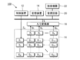
- the detection device 100 according to the first embodiment includes a control device 12, a storage device 14, an operation detection unit 16, an A / D converter 18, a sound source circuit 20, and a sound emission device 22. .
- the control device 12 is realized by a processing circuit such as a CPU (Central Processing Unit) or an FPGA (Field-Programmable Gate Array), for example, and comprehensively controls each element of the detection device 100.
- the storage device 14 stores a program executed by the control device 12 and various data used by the control device 12.
- a known recording medium such as a semiconductor recording medium or a magnetic recording medium, or a combination of a plurality of types of recording media can be used as the storage device 14.
- the motion detection unit 16 is an element that detects the operation of each key 30 of the keyboard instrument 200 (specifically, the displacement of each key 30 when the player presses the key), and a plurality (M) of light emitting units E 1.
- E M and a plurality (N) of light receiving portions R 1 to R N are natural numbers of 2 or more.
- the M light emitting units E 1 to E M and the N light receiving units R 1 to R N form a sensor matrix of vertical M rows ⁇ horizontal N columns (for example, vertical 12 rows ⁇ horizontal 8 columns), and an arbitrary 1
- the detection unit D m, n is arranged corresponding to a combination of one light emitting unit Em and one arbitrary light receiving unit R n .
- Each detection unit D m, n corresponds to a different key 30 of the keyboard 210.
- the correspondence between each detection unit D m, n and each key 30 is arbitrary.
- the detection units D m, n are illustrated for convenience for all combinations of the light emitting units Em and the light receiving units R n , but the detection units D m, n are not actually arranged. There are also combinations.
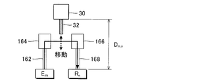
- FIG. 3 is a schematic view illustrating an arbitrary one detection unit D m, n .
- any one detection unit D m, n is a sensor head including a light emission path 162, a light guide 164, a light guide 166, a light reception path 168, and a light shield 32.
- the light emission path 162 and the light receiving path 168 are paths through which the detection light propagates, and include, for example, an optical fiber. Detection light emitted from the light emitting unit E m propagates the light emission path 162 to reach the light guide 164 and emitted to the light guide 166 side by the reflection inside of the light guide 164.
- the light shielding body 32 is a light shielding shutter fixed to the bottom surface of each key 30 of the keyboard instrument 200, for example, and moves between the light guide body 164 and the light guide body 166 in conjunction with the key depression by the user. . Therefore, the light receiving level by the light receiving elements R n (the signal level of the detection signal Q n) varies depending on the position of each key 30 (i.e., key-depression state).
- the A / D converter 18 in FIG. 2 converts the analog detection signal Q n generated by each of the N light receiving units R 1 to R N into digital data (hereinafter referred to as “light receiving level”) L.
- the control device 12 analyzes the state of each key 30 from the time series of the light reception level L after conversion by the A / D converter 18, and designates the tone generation / mute and intensity of the musical sound corresponding to each key 30 in time series.
- Performance data to be generated is generated according to the analysis result of the light reception level L.
- the performance data is stored in the storage device 14. That is, the performance of the keyboard instrument 200 by the user is recorded.
- the sound source circuit 20 of FIG. 2 generates an acoustic signal of a performance sound specified by performance data.
- the sound signal generated by the sound source circuit 20 is supplied to the sound emitting device 22 (speaker or headphone), so that the performance sound specified by the performance data is reproduced. It is also possible to realize automatic performance of the keyboard instrument 200 by driving each key 30 according to performance data by a drive mechanism (for example, a solenoid). It is also possible for the control device 12 to realize the function of the tone generator circuit 20.
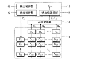
- FIG. 4 is a configuration diagram of the detection device 100 focusing on the function of the control device 12.
- the control device 12 executes a program stored in the storage device 14 to thereby control a plurality of elements (light emission control unit 42, It functions as a detection value selection unit 44 and a detection control unit 46).
- a configuration in which the function of the control device 12 is distributed to a plurality of devices, or a configuration in which a dedicated electronic circuit realizes a part of the function of the control device 12 is also adopted.
- the light emission control unit 42 sequentially causes each of the M light emitting units E 1 to E M of the operation detecting unit 16 to emit light.
- Figure 5 is an explanatory diagram of control of the light-emitting portions E m by the light emission control unit 42.
- the light emission control unit 42 includes the M light emitting units E 1 to E M. sequentially emit light each for each emission period PE m.
- the operation of sequentially causing each of the M light emitting units E 1 to E M to emit light is repeated every predetermined period (hereinafter referred to as “detection period”) P.
- the time length of the detection period P is about 1 msec, and the time length of the light emission period PE m is about 80 ⁇ sec ( ⁇ 1 / M).
- Light emission control unit 42 of the first embodiment supplies a driving signal Z m in the m-th light emission period PE m of the M light emitting period PE 1 ⁇ PE M in each detection period P on the light emitting unit E m As a result, the light emitting section Em is caused to emit light.
- Driving signal Z m is a current signal for the light emitting unit E m.
- one arbitrary light emission period PE m includes a unit period U1 and a unit period U2.
- the unit period U1 is the first half period of the light emission period PE m
- the unit period U2 is the second half period of the light emission period PE m .
- Light emission control unit 42 of the first embodiment is different from the emission level of the light emitting portion E m in the unit period U1 and the unit period U2 of each light emission period PE m.
- the light emission control unit 42 varies the signal level (specifically, the amount of current) of the drive signal Z m supplied to the light emitting unit E m between the unit period U1 and the unit period U2, thereby causing the light emitting unit Em.
- the emission level of m is varied in the light emission period PE m.
- the signal level X1 m of the drive signal Z m in the unit period U1 is below a signal level X2 m of the drive signal Z m in the unit period U2. Therefore, light emission level of the light emitting portion E m is increased stepwise in the light emission period PE m.
- the light reception level of each of the N light receiving units R 1 to R N corresponds to each light emission period. It differs in the unit period U1 and the unit period U2 in PE m.
- the A / D converter 18 applies the detection signal Q n generated by each of the N light receiving units R 1 to R N to the A / D in each of the unit period U1 and the unit period U2 in each light emission period PE m .
- the light reception level L is generated by the conversion.
- the light receiving level L2 of the light-receiving portion R n of the light receiving level L1 and the unit period U2 of the light-receiving portion R n in a unit period U1 is, for each of the N light receiving portions R 1 ⁇ R N each emission period PE m Is generated.
- Detection value selector 44 of FIG. 4 for each of the N light receiving portions R 1 ⁇ R N, the received light level L (i.e., the unit period in any of the light emission period unit period in PE m U1 and the unit period U2 U1
- the light reception level L1 at 1 and the light reception level L2 at the unit period U2) are selected as the detection values dm , n .
- Detection value d m, n since a light receiving level L of the light-receiving portion R n in the light emission period PE m light emitting unit E m emits light, detector D m, the position of the key 30 corresponding to the n (key depression) It corresponds to a numerical value indicating.
- Path length from the light emitting unit E m to the light receiving unit R n may differ in each of the N light receiving portions R 1 ⁇ R N.
- the surface state of the end face of the optical fiber constituting the light emitting path 162 or the light receiving path 168 may also be different for each of the N light receiving portions R 1 to R N.
- emitting portion E m of difference depending on the position of the emission path 162 to the light emitting surface, detecting incident from the light emitting unit E m to each of the light path 162 The amount of light can be different.
- the light receiving level L when light is emitted to any one of the light emitting portion E m may differ between the N light receiving portions R 1 ⁇ R N.
- the light emission period PE m the emission level of the light emitting portion E m by causing different signal level of the drive signal Z m supplied to each light-emitting unit E m for each unit period U (U1 or U2) while varying the inner light receiving level L of the light receiving portions R n in any unit period U in the light emission period PE m is selected for each light receiving unit R n as the detected value d m, n. That is, any of a plurality of light receiving level L (L1 and L2) are selected for each light receiving unit R n as the detected value d m, n obtained while the light emitting unit E m at different emission levels.
- the voltage dividing circuit for generating a plurality of received light signals a voltage corresponding to the received light level L divides the respective light receiving portions R n (the array of resistive elements), one of the light receiving signals from a plurality of received light signals Since an integrated circuit (multiplexer) for sequentially selecting each light emission of the light emitting unit is unnecessary in principle, it is possible to suppress the complexity of the device configuration as compared with the technique of Patent Document 1. .
- the operation of each key 30 can be detected with high accuracy while suppressing the complexity of the device configuration.
- the detection control unit 46 in FIG. 4 controls the operation detection process SB exemplified above. Specifically, the detection control unit 46 sets the signal level X2 m in the signal level X1 m and the unit period U2 in the unit period U1 in the light-emitting portion each E m (i.e. each emission period PE m).
- the detection control unit 46 sets a signal level X1 m and a signal level X2 m from a plurality of signal levels A selected in advance.
- the detection control unit 46 of the first embodiment should select the detection value selection unit 44 as the detection value dm, n which is the light reception level L1 in the unit period U1 or the light reception level L2 in the unit period U2. (hereinafter referred to as "selection level") to be set for each combination of the light emitting portion E m and the light-receiving portion R n (detection unit D m, each n).
- FIG. 6 is a flowchart of the signal level X1 m and the signal level X2 detector Selected level sets the m for each emission unit E m D m, the processing of setting for each n (hereinafter referred to as "detection control process") SA It is.
- the detection control process SA in FIG. 6 is started when the detection apparatus 100 is activated or an instruction from the user, and the operation detection process SB is started after the detection control process SA is executed.
- all the keys 30 are maintained in the key release state. That is, the detection light emitted from the light emitting unit E m reaches the each of the N light receiving portions R 1 ⁇ R N without being shielded by the light shielding member 32.
- the detection control unit 46 selects any one of the M light emitting units E 1 to E M (hereinafter referred to as “selective light emitting unit E m ”) (SA1). Then, the detection control unit 46 sets the signal level A, which is a candidate for the signal level X1 m and the signal level X2 m , to an initial value (SA2).
- the initial value of the signal level A is the minimum value among the plurality of signal levels A selected in advance.
- Detection control unit 46 causes the light-selecting light emitting unit E m by supplying a drive signal Z m of the signal level A of the present stage to the selection light emitting unit E m (SA3). Detection light emitted from the selected light emitting unit E m is reached each of the N light receiving portions R 1 ⁇ R N, the received light level L of the light receiving portions R n are outputted from the A / D converter 18. The detection control unit 46 acquires the light reception level L of each of the N light receiving units R 1 to R N from the A / D converter 18 (SA4).
- the detection control unit 46 acquires in step SA4.
- received light level L can differ for each light receiving unit R n.
- the detection control unit 46 determines whether or not the light reception level L of any of the N light receiving units R 1 to R N exceeds the threshold value L TH (the presence or absence of overflow) (SA5). When all the light receiving levels L of the N light receiving units R 1 to R N are below the threshold L TH (SA5: NO), the detection control unit 46 increases the signal level A by one step (SA6). The process proceeds to step SA3.
- SA5 the presence or absence of overflow
- the detection control unit 46 the signal level for the selected light emitting unit E m X1 m and the signal level X2 m is set according to the current signal level A (SA7). Specifically, the signal level X1 m of the unit period U1 is set to a signal level A that is one stage lower than the current signal level A, and the signal level X2 m of the unit period U2 is set to the current signal level A. The Or more signal level is set in step X1 m and the signal level X2 m is stored in the storage device 14 for each emission unit E m.
- FIG. 7 is an explanatory diagram for setting the signal level X1 m and the signal level X2 m .
- the light reception level L of each of the N light receiving units R 1 to R N and the threshold value L TH The relationship is illustrated.
- the signal level A2 in stage 2 exceeds the signal level A1 in stage 1
- the signal level A3 in stage 3 exceeds the signal level A2 in stage 2 (A1 ⁇ A2 ⁇ A3).
- stage 1 since all the received light levels L of the N light receiving units R 1 to R N are lower than the threshold value L TH (SA5: NO), the signal level A2 that exceeds the signal level A1 by one stage is used. proceed.
- step 2 since all the light receiving levels L of the N light receiving units R 1 to R N are lower than the threshold value L TH (SA5: NO), the signal level A3 that exceeds the signal level A2 by one step is used. Proceed to 3.
- stage 3 the light receiving level L of three light receiving units R 1 to R 3 out of N exceeds the threshold value L TH (SA5: YES). Therefore, the signal level A2 in the previous stage 2 is adopted as the signal level X1 m in the unit period U1, and the signal level A3 in stage 3 is adopted as the signal level X2 m in the unit period U2 (SA7 ).
- the detection control unit 46 of the first embodiment among the signal levels X1 m and the signal level X2 m, the received light level L is a threshold of the light-receiving portion R n when supplied to the selected light emitting unit E m L TH Is selected as the selection target level in the motion detection process SB.
- step SA8 for designating either the signal level X1 m or the signal level X2 m as the selection target level is the process of designating either the unit period U1 or the unit period U2 as the selection target level, or the light receiving level.
- the process can designate either L1 or light reception level L2 as the selection target level.
- the set selection level in step it is stored for each combination of the light emitting portion E m and the light-receiving portion R n in the storage device 14. It is also possible to reverse the order of step SA7 and step SA8.
- the detection control unit 46 determines whether or not the above processing (SA1 to SA8) has been completed for all of the M light emitting units E 1 to E M of the motion detection unit 16 (SA9). When the determination is negative (SA9: NO), the detection control unit 46, after selecting the light emitting portion E m unprocessed among the M light emitting unit E 1 ⁇ E M as selecting the light emitting unit E m ( SA1), selecting light emitting unit E m after the update executes subsequent processing (SA2 ⁇ SA9) for. When the setting of the signal level X1 m and the signal level X2 m (SA7) and the setting of the selection target level (SA8) are completed for the M light emitting units E 1 to E M (SA9: YES), FIG. The detection control process SA ends.
- FIG. 8 is a flowchart of the operation detection process SB executed based on the result of the detection control process SA exemplified above.
- the operation detection process SB of FIG. 8 is executed in each of the M light emission periods PE 1 to P E M in each detection cycle P in response to the completion of the detection control process SA or an instruction from the user.
- the light emission control unit 42 among the M light emission units E 1 to E M corresponds to the light emission unit E m (hereinafter referred to as the light emission period PE m).
- “Drive light emitting unit E m ”) is selected (SB1).
- Light emission control unit 42 identifies the signal level X1 m and the signal level X2 m set by the detection control process SA for driving the light emitting unit E m (SB2). Specifically, the light emission control unit 42 acquires a signal level X1 m and the signal level X2 m of driving the light emitting unit E m from the storage device 14.
- the light emission control unit 42 When the unit period U1 emission period PE m arrives, the light emission control unit 42, light emission driving light emitting unit E m by supplying a drive signal Z m of the specified signal level X1 m in step SB2 to drive the light emitting unit E m (SB3).
- a / D converter 18, N by driving the light emitting unit A / D conversion of the detection signal Q n, each of which outputs of the N receiving portions R 1 ⁇ R N during emission of E m in the unit period U1
- the light receiving level L1 is specified.
- Detection value selector 44 obtains the N pieces of light receiving level L1 of the light-receiving portions R n from the A / D converter 18 (SB4).
- the light emission control unit 42 is driven by supplying the drive light emission unit E m with the drive signal Z m of the signal level X2 m specified in step SB2 for the unit period U2. causing the light emitting portion E m (SB5).
- a / D converter 18, the detection signal Q n, each of the N light receiving portions R 1 ⁇ R N is output during light emission driving the light emitting portion E m of the unit period U2
- a / D conversion of N The light reception level L2 is specified.
- Detection value selector 44 obtains the N pieces of light receiving level L2 of the light receiving portions R n from the A / D converter 18 (SB6).
- the light reception level L1 in the unit period U1 and the light reception level L2 in the unit period U2 are measured for each of the N light receiving units R 1 to R N.
- the detection value selection unit 44 selects either the light reception level L1 or the light reception level L2 as the detection value dm , n for each of the N light receiving units R 1 to R N (SB7).
- the light reception level L in the unit period U in which the drive signal Z m having the signal level (X1 m or X2 m ) designated as is supplied to the drive light emitting unit E m is selected as the detection value dm , n .
- the detection value dm , n is adopted.
- detection processing SB is repeated for each emission period PE m above, the detection unit D m, n states of (each key corresponding to a combination of the two light emitting portions E m and the light-receiving portion R n Detection value dm , n corresponding to 30 operations) is sequentially generated for each detection period P.
- the control device 12 generates performance data by analyzing the time series of the detected values dm , n of each key 30 (time change of displacement of each key 30).
- the signal level within a range in which the light receiving level L of the light-receiving portion R n is below the threshold value L TH is set for each combination of the light-receiving portion R n and the light emitting unit E m, the light emitting Of the unit period U1 and unit period U2 within the period PE m , the light reception level L of the light receiving unit R n in the unit period U in which the drive signal Z m of the signal level is supplied to the light emitting unit E m is the detected value d m. , n . Therefore, there is an advantage that the detection value dm , n within an appropriate range below the threshold L TH can be generated.
- Second Embodiment A second embodiment of the present invention will be described.
- elements having the same functions or functions as those of the first embodiment will be referred to with the same reference numerals used in the description of the first embodiment, and detailed descriptions thereof will be omitted as appropriate.
- FIG. 9 is a waveform diagram of the detection signal Q n output from any one light receiving unit R n .
- the actual detection signal Q n signal levels e.g. current amount
- the signal level of the detection signal Q n may vary unstably immediately after the light emission level of the light emitting portion E m is varied at the start point t1 of the unit period U (U1 or U2).
- stable period PS detection by the A / D converter 18 within a period PS (hereinafter referred to as “stable period”) PS of each unit period U during which the signal level of the detection signal Q n is stable.
- a / D conversion of the signal Q n generation of a light receiving level L is executed.
- the stable period PS is, for example, a period between a time point t2 when a predetermined time length TA (for example, about 18 ⁇ sec) has elapsed from the start point t1 of each unit period U and an end point t3 of the unit period U.
- the time length TB of the stable period PS is, for example, about 20 ⁇ sec to 23 ⁇ sec.
- a / D converter 18 starts the A / D conversion of the detection signal Q n from the time t2 delayed by a time length TA relative starting point t1 of the unit period U for generating a light receiving level L.
- a / D conversion within the time length TA for a period (i.e. period signal level of the detection signal Q n varies unstably) from the start point t1 of each unit period U to time t2 is not executed.
- Detection value selector 44 of the second embodiment acquires the received light level L in the stable period PS (L1 and L2) in each unit period U in the emission period PE m.
- the operation in which the detection value selection unit 44 selects either the light reception level L1 of the unit period U1 or the light reception level L2 of the unit period U2 as the detection value dm , n is the same as in the first embodiment.
- the received light level (signal level of the detection signal Q n) is the detection value selector 44 to the light receiving level L in the stable period PS to stably acquire among the unit period U. Therefore, the detection value selector 44 obtains the received light level L in the period during which the signal level of the detection signal Q n varies unstably (e.g. the period from the starting point t1 of the unit period U to time t2) of each of the unit periods U.
- an accurate detection value dm , n can be generated (and the operation of each key 30 can be detected with high accuracy) as compared with the configuration to be performed.
- the A / D conversion of the detection signal Q n by the A / D converter 18 starts from the start point t1 of the unit period U, while the light reception level L generated within the unit period U is within the stable period PS. It is also possible for the detection value selection unit 44 to select the light reception level L.
- each light emission period PE m includes two unit periods U (U1 or U2) is exemplified, but the total number K of unit periods U in the light emission period PE m is 2 It is not limited to pieces. That is, it is also possible to include three or more unit periods U in each emission period PE m.
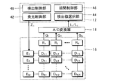
- FIG. 10 is a configuration diagram focusing on the function of the control device 12 of the detection device 100 according to the third embodiment.
- the control device 12 of the third embodiment includes a period control unit 48 in addition to the same elements (light emission control unit 42, detection value selection unit 44, and detection control unit 46) as in the first embodiment. Also works.
- Period control unit 48 controls the time length T of the total number K and the unit period U of the unit period U in each emission period PE m.
- the period control unit 48 of the third embodiment includes the light emission period PE m in accordance with the time length TA from the start point of each unit period U to the time point t2 when the signal level of the detection signal Q n is stabilized.
- the total number K of unit periods U and the time length T of each unit period U are controlled.
- the time length T of the unit period U is the sum of the time length TA from the start point t1 to the time point t2 of the unit period U and the time length TB of the stable period PS.
- a / D converter 18 is a point to start the A / D conversion of the detection signal Q n at the point of the unit period U t2 (the starting point of the stable period PS) is the same as in the second embodiment.
- the period control section 48 sets the sum of the time length TA and the predetermined time length TB as the time length T of the unit period U. Since the time length TB of the stable period PS is fixed to, for example, the time length necessary for the generation of the received light level L by the A / D converter 18, the entire time length T of the unit period U is variable according to the time length TA. It is long.
- the period control unit 48 sets the total number K of the unit period U in the arc period PE m according to the time length T of the unit period U determined in the above procedure. Specifically, the period control unit 48 sets the maximum number of unit periods U (time length T) that can be included in the light emission period PE m having a predetermined length as the total number K. Therefore, as the detection signal Q n stably duration TA required signal level is short, the total number K of the unit period U in the emission period PE m increases.
- the time length of light emission period PE m and detection period P is fixed to a predetermined value.
- each light-emitting unit E m for each of the signal level of the unit period U1 ⁇ UK of the total number K of period control unit 48 sets (X1 m ⁇ XK m) Set.
- the detection control unit 46 receiving the respective signal levels X1 m ⁇ XK any driving signal Z m the light emitting unit E N pieces of light-receiving portion when supplied to the m R 1 ⁇ R N of m
- the signal levels X1 m to XK m are set so that the level L is lower than the threshold value L TH .
- the detection control unit 46 should select the light reception level L in the unit period U among the K unit periods U1 to UK within the light emission period PE m as the detection value dm , n (selection target level). the set for each combination of the light emitting portion E m and the light receiver R n.
- the detection value selector 44 a light receiving level Lk of a unit period Uk of the K unit periods U1 ⁇ detection control process SA in selection level set signal level Xk m of UK for each emission period PE m
- the detection value dm , n is selected (SB7).
- the same effect as that of the first embodiment or the second embodiment is realized.
- the total number K of unit periods U in each light emission period PE m and the time length T of each unit period U are determined according to the time length TA until the signal level of the detection signal Q n is stabilized. Be changed. Therefore, the configuration to increase the total number K of an exemplary manner for example, the time length TA is shorter unit period U described above, to compensate for errors in the received light level L of each light-receiving portion R n with high accuracy (and thus of the keys 30 It is possible to detect movement with high accuracy.
- the signal level of the magnitude of the driving signal Z m in a plurality of unit periods U in the emission period PE m are arbitrary.
- a configuration in which the light emission level of the light emitting portion E m decreases stepwise within PE m may also be employed.
- the detection control process SA in each embodiment described above although the signal level A of the driving signal Z m was stepwise increased from the initial value, stepwise reduces the signal level A of the driving signal Z m from a maximum value while it is also possible to perform the supply of the driving signal Z m for the selected light emitting unit E m (SA3), and an acquisition (SA4) of light receiving level L of the light receiving portions R n.
- SA3 selected light emitting unit E m
- SA4 acquisition of light receiving level L of the light receiving portions R n.
- the detection control unit 46 determines whether or not the light reception level L of any of the N light receiving units R 1 to R N is lower than the threshold value L TH .
- the signal level X1 m or signal level X2 m set in the past (typically immediately before) detection control process SA can be used as the initial value (SA2) of the signal level A in the detection control process SA. It is.
- the detection control unit 46 has the light reception levels L of the N light receiving units R 1 to R N within a predetermined range (upper limit value) when the driving signal Z m is supplied to the light emitting unit E m .
- a plurality of signal levels to be within the range) above the range or the lower limit value below is generically represented as an element set for each combination of the light emitting portion E m and the light receiver R n.
- the detection device 100 that detects the operation of each key 30 of the keyboard instrument 200 is illustrated, but the detection target by the detection device 100 is not limited to the key 30.
- the detection of the operation of each of a plurality of hammers that strike a string in the keyboard instrument 200 or the detection of the operation of each of a plurality of operators (for example, buttons or knobs) that are arbitrarily operated by the user is also described above.
- a detection device 100 similar to each embodiment can be used.
- the object to be detected by the detection apparatus 100 is comprehensively expressed as a movable movable body.
- the detection device 100 exemplified in each of the above-described embodiments is realized by the cooperation of the control device 12 and a program.
- a program according to a preferred embodiment of the present invention includes M light emitting units E 1 to E M and N light receiving units R 1 to R N , and includes a phase between each light emitting unit E m and each light receiving unit R n.
- a controllable computer operation detection unit 16 which received light level L is changed in the light-receiving portion R n according to the combination corresponding to the movable body, a drive
- each of the M light emitting units E 1 to E M is caused to emit light sequentially for each light emission period PE m, and in each of the plurality of unit periods U within the light emission period PE m , the drive signal Z m
- the light reception level L in any one of the plurality of unit periods U within the light emission period PE m is detected as a value d m.
- the programs exemplified above can be provided in a form stored in a computer-readable recording medium and installed in the computer.
- the recording medium is, for example, a non-transitory recording medium, and an optical recording medium (optical disk) such as a CD-ROM is a good example, but a known arbitrary one such as a semiconductor recording medium or a magnetic recording medium This type of recording medium can be included.
- the non-transitory recording medium includes any recording medium except for a transient propagation signal (transitory, propagating signal), and does not exclude a volatile recording medium. It is also possible to provide a program to a computer in the form of distribution via a communication network. It is also possible to distribute the program to a computer in the form of distribution via a communication network.
- a preferred aspect of the present invention can also be specified as an operation method (detection method) of the detection apparatus 100 exemplified in the above embodiments.
- the detection method (motion detection process SB) includes M light emitting units E 1 to E M and N light receiving units R 1 to R N, and each light emitting unit E m depending on the operation of the mobile body corresponding to different combinations of the light-receiving portion R n (eg key 30), the operation detection unit 16 which received light level L is changed in the light-receiving portion R n according to the combination corresponding to the mobile controllable computer, the drive signal Z m with sequentially emit light of each of the M light emitting unit E 1 ⁇ E M for each emission period PE m by supplying a plurality of unit periods in the emission period PE m U in each is differentiated signal level of the drive signal Z m, for each of the N light receiving portions R 1 ⁇ R N, the detection value received light level L in any of the plurality of unit
- a detection device includes a plurality of light emitting units and a plurality of light receiving units, and is in a different combination of any of the plurality of light emitting units and any of the plurality of light receiving units.
- the operation detecting section in which the light receiving level of the light receiving section according to the combination corresponding to the moving body is changed, and each of the plurality of light emitting sections is sequentially supplied for each light emitting period by supplying a driving signal.
- a detection value selection unit that selects a light reception level in any one of the light emission periods as a detection value.
- the signal level (for example, current value) of the drive signal supplied to each light emitting unit is varied for each unit period to vary the light emission level of each light emitting unit within the light emitting period, while within the light emitting period.
- the light receiving level of each light receiving unit in any unit period is selected for each light receiving unit as a detection value. Therefore, it is possible to compensate for an error in the light receiving level for each light receiving unit (and thus detect the operation of the moving body with high accuracy).
- a voltage dividing circuit (an array of a plurality of resistance elements) that divides a voltage according to a light receiving level of each light receiving unit to generate a plurality of light receiving signals, and one light receiving signal from the plurality of light receiving signals is transmitted to the light emitting unit. Since an integrated circuit (multiplexer) for sequentially selecting each light emission is unnecessary in principle, it is possible to suppress the complexity of the device configuration as compared with the technique of Patent Document 1.
- the detection apparatus according to a preferred example (aspect 2) of aspect 1 is configured such that, for each combination of any of the plurality of light emitting parts and any of the plurality of light receiving parts, the light receiving part at the time of supplying a drive signal to the light emitting part.
- a detection control unit configured to set a plurality of signal levels within a predetermined range of the light reception level, and the light emission control unit includes any one of the plurality of signal levels in each of the plurality of unit periods in the light emission period.
- Each of the plurality of light emitting units emits light
- the detection value selecting unit sets the combination of the light emitting unit and the light receiving unit among the plurality of unit periods in the light emitting period.
- the light receiving level of the light receiving unit in a unit period in which a signal level drive signal is supplied to the light emitting unit is selected as a detection value.
- a signal level at which the light receiving level of the light receiving unit falls within a predetermined range (for example, a signal level whose light receiving level is lower than the threshold) is set for each combination of the light emitting unit and the light receiving unit, and a plurality of light levels within the light emitting period are set.
- the light receiving level of the light receiving unit in the unit period in which the drive signal of the signal level is supplied to the light emitting unit is selected as the detection value. Therefore, it is possible to generate a detection value within an appropriate range.
- the detected value selection unit is configured to receive a light reception level within a stable period in which the light reception level is stable in each of the plurality of unit periods within the light emission period. And the received light level in any of the plurality of unit periods is selected as a detection value.
- the detection value selection unit acquires the light reception level within the stable period in which the light reception level is stable in the unit period, the period in which the light reception level fluctuates in an unstable manner in the unit period (for example, the start point of the unit period).
- the detection apparatus is configured so that the total number of unit periods in the light emission period and the time of each unit period are in accordance with the time length from the start point of the unit period to the time when the light reception level is stabilized.
- a period control unit for controlling the length is provided.
- the total number of unit periods in the light emission period and the time length of each unit period are controlled according to the time length from the start point of the unit period to the time when the light reception level is stabilized.
- a keyboard instrument includes a plurality of keys and a detection device that detects the operation of each of the plurality of keys.
- the detection device includes a plurality of light emitting units and a plurality of light emission units.
- the light receiving unit of the light receiving unit and the light receiving unit of the light receiving unit according to the combination corresponding to the key according to the operation of the key corresponding to a different combination of any of the plurality of light emitting units An operation detecting unit whose level changes, and each of the plurality of light emitting units emits light sequentially in each light emitting period by supplying a driving signal, and the signal level of the driving signal in each of the plurality of unit periods in the light emitting period And a detection value selection unit that selects, for each of the light emission periods, a light reception level in any one of the plurality of unit periods within the light emission period as a detection value for each of the plurality of light reception units.
- a program according to a preferred aspect (aspect 7) of the present invention includes a plurality of light emitting units and a plurality of light receiving units, and corresponds to different combinations of each of the plurality of light emitting units and each of the plurality of light receiving units.
- Each of the plurality of light emitting units emits light by supplying a drive signal to a computer capable of controlling an operation detecting unit in which the light receiving level of the light receiving unit according to the combination corresponding to the moving body changes according to the operation of the moving body.
- a light emission control process that sequentially emits light for each period, and in each of a plurality of unit periods within the light emission period, and a signal level of the drive signal is different, and for each of the plurality of light receiving units, A detection value selection process is performed in which the light reception level in any of the plurality of unit periods is selected as a detection value for each light emission period.
- a detection method according to a preferred aspect (aspect 8) of the present invention includes a plurality of light emitting units and a plurality of light receiving units, and each of the plurality of light emitting units and each of the plurality of light receiving units has a different combination.
- a computer capable of controlling an operation detection unit in which the light receiving level of the light receiving unit associated with the combination corresponding to the moving body changes according to the operation of the corresponding moving unit is configured to supply each of the plurality of light emitting units by supplying a drive signal.
- the light emission is sequentially performed for each light emission period, the signal level of the drive signal is made different in each of the plurality of unit periods in the light emission period, and the plurality of units in the light emission period for each of the plurality of light receiving units.
- the light reception level in any one of the periods is selected as the detection value for each light emission period.
Landscapes
- Engineering & Computer Science (AREA)
- Physics & Mathematics (AREA)
- General Engineering & Computer Science (AREA)
- Theoretical Computer Science (AREA)
- Acoustics & Sound (AREA)
- Multimedia (AREA)
- General Physics & Mathematics (AREA)
- Human Computer Interaction (AREA)
- Electrophonic Musical Instruments (AREA)
- Geophysics And Detection Of Objects (AREA)
- Circuit Arrangement For Electric Light Sources In General (AREA)
Abstract
検出装置は、複数の発光部と複数の受光部とを含み、前記複数の発光部の何れかと前記複数の受光部の何れかとの相異なる組合せに対応する移動体の動作に応じて、当該移動体に対応する組合せに係る受光部の受光レベルが変化する動作検出部と、駆動信号の供給により前記複数の発光部の各々を発光期間毎に順次に発光させ、当該発光期間内の複数の単位期間の各々においては前記駆動信号の信号レベルを相違させる発光制御部と、前記複数の受光部の各々について、前記発光期間内の前記複数の単位期間の何れかにおける受光レベルを検出値として前記発光期間毎に選択する検出値選択部とを具備する。
Description
本発明は、鍵盤楽器の鍵等の複数の移動体の動作を検出する技術に関する。
鍵盤楽器の鍵等の移動体の動作を光学的に検出するための検出装置においては、製造誤差または経年変化に起因した受光素子または発光素子の特性誤差が問題となる。特許文献1には、複数の発光部の各々と複数の受光部の各々との組合せにより複数の操作子の動作を検出する構成のもとで、発光部毎の発光レベルと受光部毎の受光レベルとを調整する技術が開示されている。特許文献1の技術では、複数の受光部の何れの出力信号も所定の閾値を上回らないように各発光部の発光レベルが決定される一方、受光部の受光レベルに応じた電圧を分圧した複数の受光信号のうち、特定の発光レベルのもとで閾値を下回る最大の受光信号が出力信号として選択される。
特許文献1の技術のように発光部毎に発光レベルを特定の数値に調整しても、1個の発光部の発光時における受光部毎の受光レベルの誤差は補償されない。受光部毎の受光レベルの誤差を低減する観点から、特許文献1の技術では、各受光部の受光レベルに応じて並列に生成された複数の受光信号の何れかを選択する構成を採用する。しかし、以上の構成では、受光部の受光レベルに応じた電圧の分圧で複数の受光信号を生成する分圧回路(複数の抵抗素子の配列)と、複数の受光信号から1個の受光信号を発光部の発光毎に順次に選択するための集積回路(マルチプレクサ)とが必要であるから、装置構成が複雑化するという問題がある。以上の事情を考慮して、本発明は、装置構成の複雑化を抑制しながら複数の移動体の動作を高精度に検出することを目的とする。
以上の課題を解決するために、本発明の好適な態様に係る検出装置は、複数の発光部と複数の受光部とを含み、前記複数の発光部の何れかと前記複数の受光部の何れかとの相異なる組合せに対応する移動体の動作に応じて、当該移動体に対応する組合せに係る受光部の受光レベルが変化する動作検出部と、駆動信号の供給により前記複数の発光部の各々を発光期間毎に順次に発光させ、当該発光期間内の複数の単位期間の各々においては前記駆動信号の信号レベルを相違させる発光制御部と、前記複数の受光部の各々について、前記発光期間内の前記複数の単位期間の何れかにおける受光レベルを検出値として前記発光期間毎に選択する検出値選択部とを具備する。
本発明の好適な態様に係る鍵盤楽器は、複数の鍵と、前記複数の鍵の各々の動作を検出する検出装置とを具備し、前記検出装置は、複数の発光部と複数の受光部とを含み、前記複数の発光部の何れかと前記複数の受光部の何れかとの相異なる組合せに対応する前記鍵の動作に応じて、当該鍵に対応する組合せに係る受光部の受光レベルが変化する動作検出部と、駆動信号の供給により前記複数の発光部の各々を発光期間毎に順次に発光させ、当該発光期間内の複数の単位期間の各々においては前記駆動信号の信号レベルを相違させる発光制御部と、前記複数の受光部の各々について、前記発光期間内の前記複数の単位期間の何れかにおける受光レベルを検出値として前記発光期間毎に選択する検出値選択部とを含む。
本発明の好適な態様に係るプログラムは、複数の発光部と複数の受光部とを含み、前記複数の発光部の何れかと前記複数の受光部の何れかとの相異なる組合せに対応する移動体の動作に応じて、当該移動体に対応する組合せに係る受光部の受光レベルが変化する動作検出部を制御可能なコンピュータに、駆動信号の供給により前記複数の発光部の各々を発光期間毎に順次に発光させ、当該発光期間内の複数の単位期間の各々においては前記駆動信号の信号レベルを相違させる発光制御処理、および、前記複数の受光部の各々について、前記発光期間内の前記複数の単位期間の何れかにおける受光レベルを検出値として前記発光期間毎に選択する検出値選択処理を実行させる。
本発明の好適な態様に係る検出方法は、複数の発光部と複数の受光部とを含み、前記複数の発光部の何れかと前記複数の受光部の何れかとの相異なる組合せに対応する移動体の動作に応じて、当該移動体に対応する組合せに係る受光部の受光レベルが変化する動作検出部を制御可能なコンピュータにおいて、駆動信号の供給により前記複数の発光部の各々を発光期間毎に順次に発光させ、当該発光期間内の複数の単位期間の各々においては前記駆動信号の信号レベルを相違させ、前記複数の受光部の各々について、前記発光期間内の前記複数の単位期間の何れかにおける受光レベルを検出値として前記発光期間毎に選択する。
本発明の好適な態様に係る鍵盤楽器は、複数の鍵と、前記複数の鍵の各々の動作を検出する検出装置とを具備し、前記検出装置は、複数の発光部と複数の受光部とを含み、前記複数の発光部の何れかと前記複数の受光部の何れかとの相異なる組合せに対応する前記鍵の動作に応じて、当該鍵に対応する組合せに係る受光部の受光レベルが変化する動作検出部と、駆動信号の供給により前記複数の発光部の各々を発光期間毎に順次に発光させ、当該発光期間内の複数の単位期間の各々においては前記駆動信号の信号レベルを相違させる発光制御部と、前記複数の受光部の各々について、前記発光期間内の前記複数の単位期間の何れかにおける受光レベルを検出値として前記発光期間毎に選択する検出値選択部とを含む。
本発明の好適な態様に係るプログラムは、複数の発光部と複数の受光部とを含み、前記複数の発光部の何れかと前記複数の受光部の何れかとの相異なる組合せに対応する移動体の動作に応じて、当該移動体に対応する組合せに係る受光部の受光レベルが変化する動作検出部を制御可能なコンピュータに、駆動信号の供給により前記複数の発光部の各々を発光期間毎に順次に発光させ、当該発光期間内の複数の単位期間の各々においては前記駆動信号の信号レベルを相違させる発光制御処理、および、前記複数の受光部の各々について、前記発光期間内の前記複数の単位期間の何れかにおける受光レベルを検出値として前記発光期間毎に選択する検出値選択処理を実行させる。
本発明の好適な態様に係る検出方法は、複数の発光部と複数の受光部とを含み、前記複数の発光部の何れかと前記複数の受光部の何れかとの相異なる組合せに対応する移動体の動作に応じて、当該移動体に対応する組合せに係る受光部の受光レベルが変化する動作検出部を制御可能なコンピュータにおいて、駆動信号の供給により前記複数の発光部の各々を発光期間毎に順次に発光させ、当該発光期間内の複数の単位期間の各々においては前記駆動信号の信号レベルを相違させ、前記複数の受光部の各々について、前記発光期間内の前記複数の単位期間の何れかにおける受光レベルを検出値として前記発光期間毎に選択する。
<第1実施形態>
図1は、本発明の第1実施形態に係る鍵盤楽器200の構成図である。図1に例示される通り、第1実施形態の鍵盤楽器200は、鍵盤210と検出装置100とを具備する。鍵盤210は、白鍵および黒鍵を含む複数(例えば88個)の鍵30を含んで構成される。
図1は、本発明の第1実施形態に係る鍵盤楽器200の構成図である。図1に例示される通り、第1実施形態の鍵盤楽器200は、鍵盤210と検出装置100とを具備する。鍵盤210は、白鍵および黒鍵を含む複数(例えば88個)の鍵30を含んで構成される。
図2は、本発明の第1実施形態に係る検出装置100の構成図である。第1実施形態の検出装置100は、鍵盤楽器200に使用されて複数の鍵30の各々の動作を光学的に検出するセンサである。図2に例示される通り、第1実施形態の検出装置100は、制御装置12と記憶装置14と動作検出部16とA/D変換器18と音源回路20と放音機器22とを具備する。
制御装置12は、例えばCPU(Central Processing Unit)またはFPGA(Field-Programmable Gate Array)等の処理回路で実現され、検出装置100の各要素を統括的に制御する。記憶装置14は、制御装置12が実行するプログラムと制御装置12が使用する各種のデータとを記憶する。例えば半導体記録媒体または磁気記録媒体等の公知の記録媒体、または複数種の記録媒体の組合せが記憶装置14として使用され得る。
動作検出部16は、鍵盤楽器200の各鍵30の動作(具体的には演奏者による押鍵時の各鍵30の変位)を検出する要素であり、複数(M個)の発光部E1~EMと複数(N個)の受光部R1~RNとを具備する(MおよびNは2以上の自然数)。任意の1個の発光部Em(m=1~M)は、例えばLED(Light Emitting Diode)等の発光素子を含んで構成され、駆動信号Zmの供給により光(以下「検出光」という)を放射する。任意の1個の受光部Rn(n=1~N)は、例えばフォトダイオード等の受光素子を含んで構成され、受光レベルに応じた検出信号Qnを生成する。
M個の発光部E1~EMとN個の受光部R1~RNとは縦M行×横N列(例えば縦12行×横8列)のセンサマトリクスを構成し、任意の1個の発光部Emと任意の1個の受光部Rnとの組合せに対応して検出部Dm,nが配置される。各検出部Dm,nは、鍵盤210の相異なる鍵30に対応する。なお、各検出部Dm,nと各鍵30との対応関係は任意である。また、図2では、各発光部Emと各受光部Rnとの全通りの組合せについて検出部Dm,nを便宜的に図示したが、実際には検出部Dm,nが配置されない組合せも存在する。
図3は、任意の1個の検出部Dm,nを例示する模式図である。図3に例示される通り、任意の1個の検出部Dm,nは、発光経路162と導光体164と導光体166と受光経路168と遮光体32とを具備するセンサヘッドである。発光経路162および受光経路168は、検出光が伝播する経路であり、例えば光ファイバを含んで構成される。発光部Emから出射した検出光は、発光経路162を伝播して導光体164に到達し、導光体164の内部での反射により導光体166側に出射する。導光体164から導光体166に入射した検出光は、導光体166の内部での反射により受光経路168に入射し、受光経路168を伝播して受光部Rnに到達する。遮光体32は、例えば鍵盤楽器200の各鍵30の底面に固定された遮光性のシャッタであり、利用者による押鍵に連動して導光体164と導光体166との間に移動する。したがって、各受光部Rnによる受光レベル(検出信号Qnの信号レベル)は、各鍵30の位置(すなわち押鍵状態)に応じて変動する。
動作検出部16の第m行に対応するN個の検出部Dm,1~Dm,Nの各々の発光経路162には、第m番目の1個の発光部Emから出射した検出光が共通に供給され、動作検出部16の第n列に対応するM個の検出部D1,n~DM,nの各々の受光経路168を通過した検出光は第n番目の1個の受光部Rnにより受光される。したがって、任意の1個の発光部Emの発光時におけるN個の受光部R1~RNの各々の受光レベルを検出することで、発光部Emと各受光部Rnとの組合せに対応する各鍵30の動作(検出部Dm,nの状態)を検出することが可能である。なお、例えば特開平9-152871号公報に開示される通り、1個の発光部Emから出射した検出光を複数の受光部Rnで受光する構成、または、複数の発光部Emから出射した検出光を1個の受光部Rnで受光する構成も採用され得る。
図2のA/D変換器18は、N個の受光部R1~RNの各々が生成したアナログの検出信号Qnをデジタルデータ(以下「受光レベル」という)Lに変換する。制御装置12は、A/D変換器18による変換後の受光レベルLの時系列から各鍵30の状態を解析し、各鍵30に対応する楽音の発音/消音と強度とを時系列に指定する演奏データを受光レベルLの解析結果に応じて生成する。演奏データは記憶装置14に格納される。すなわち、利用者による鍵盤楽器200の演奏が記録される。図2の音源回路20は、演奏データで指定される演奏音の音響信号を生成する。音源回路20が生成した音響信号が放音機器22(スピーカまたはヘッドホン)に供給されることで、演奏データで指定される演奏音が再生される。なお、駆動機構(例えばソレノイド)が演奏データに応じて各鍵30を駆動することで鍵盤楽器200の自動演奏を実現することも可能である。また、音源回路20の機能を制御装置12が実現することも可能である。
図4は、制御装置12の機能に着目した検出装置100の構成図である。図4に例示される通り、第1実施形態の制御装置12は、記憶装置14に記憶されたプログラムを実行することで、動作検出部16を制御するための複数の要素(発光制御部42,検出値選択部44および検出制御部46)として機能する。なお、制御装置12の機能を複数の装置に分散した構成、または、制御装置12の機能の一部を専用の電子回路が実現する構成も採用される。
発光制御部42は、動作検出部16のM個の発光部E1~EMの各々を順次に発光させる。図5は、発光制御部42による各発光部Emの制御の説明図である。図5に例示される通り、鍵盤楽器200の各鍵30の動作を検出する処理(以下「動作検出処理」という)SBにおいて、発光制御部42は、M個の発光部E1~EMの各々を発光期間PEm毎に順次に発光させる。M個の発光部E1~EMの各々を順次に発光させる動作は、所定の周期(以下「検出周期」という)P毎に反復される。検出周期Pの時間長は1msec程度であり、発光期間PEmの時間長は80μsec(≒1/M)程度である。第1実施形態の発光制御部42は、各検出周期P内のM個の発光期間PE1~PEMのうち第m番目の発光期間PEmにて駆動信号Zmを発光部Emに供給することで当該発光部Emを発光させる。駆動信号Zmは、発光部Emを発光させる電流信号である。
図5に例示される通り、任意の1個の発光期間PEmは、単位期間U1と単位期間U2とを包含する。例えば、単位期間U1は発光期間PEmの前半期間であり、単位期間U2は発光期間PEmの後半期間である。第1実施形態の発光制御部42は、各発光期間PEmの単位期間U1と単位期間U2とで発光部Emの発光レベルを相違させる。具体的には、発光制御部42は、発光部Emに供給する駆動信号Zmの信号レベル(具体的には電流量)を単位期間U1と単位期間U2とで相違させることにより発光部Emの発光レベルを発光期間PEm内で変動させる。図5に例示される通り、単位期間U1での駆動信号Zmの信号レベルX1mは、単位期間U2での駆動信号Zmの信号レベルX2mを下回る。したがって、発光期間PEm内で発光部Emの発光レベルが段階的に増加する。
以上の例示の通り、第1実施形態では、各発光期間PEm内で発光部Emの発光レベルが変動するから、N個の受光部R1~RNの各々の受光レベルは各発光期間PEm内の単位期間U1と単位期間U2とで相違する。A/D変換器18は、N個の受光部R1~RNの各々が生成する検出信号Qnを、各発光期間PEm内の単位期間U1および単位期間U2の各々にてA/D変換することで受光レベルLを生成する。すなわち、単位期間U1での受光部Rnの受光レベルL1と単位期間U2での受光部Rnの受光レベルL2とが、N個の受光部R1~RNの各々について発光期間PEm毎に生成される。
図4の検出値選択部44は、N個の受光部R1~RNの各々について、発光期間PEm内の単位期間U1および単位期間U2の何れかにおける受光レベルL(すなわち、単位期間U1での受光レベルL1と単位期間U2での受光レベルL2との何れか)を検出値dm,nとして選択する。検出値dm,nは、発光部Emが発光する発光期間PEmにおける受光部Rnの受光レベルLであるから、検出部Dm,nに対応する鍵30の位置(押鍵状態)を示す数値に相当する。
発光部Emから受光部Rnまでの経路長(発光経路162および受光経路168での光損失)はN個の受光部R1~RNの各々で相違し得る。発光経路162または受光経路168を構成する光ファイバの端面の表面状態もN個の受光部R1~RNの各々で相違し得る。また、発光面の面内で検出光の強度が相違する発光部Emを採用した構成では、発光面に対する発光経路162の位置に応じて、発光部Emから各発光経路162に入射する検出光の光量が相違し得る。製造誤差または経年変化に起因して受光部Rnの特性(例えば受光量と検出信号Qnの信号レベルとの関係)が受光部Rn毎に相違する可能性もある。以上に例示した種々の相違に起因して、任意の1個の発光部Emを発光させたときの受光レベルLはN個の受光部R1~RNの間で相違し得る。
第1実施形態では、各発光部Emに供給される駆動信号Zmの信号レベルを単位期間U(U1またはU2)毎に相違させることで各発光部Emの発光レベルを発光期間PEm内で変動させる一方、発光期間PEm内の何れかの単位期間Uにおける各受光部Rnの受光レベルLが検出値dm,nとして受光部Rn毎に選択される。すなわち、発光部Emを相異なる発光レベルで発光させたときの複数の受光レベルL(L1およびL2)の何れかが検出値dm,nとして受光部Rn毎に選択される。したがって、受光部Rn毎の受光レベルLの誤差を補償する(ひいては各鍵30の動作を高精度に検出する)ことが可能である。また、各受光部Rnの受光レベルLに応じた電圧を分圧して複数の受光信号を生成する分圧回路(複数の抵抗素子の配列)と、複数の受光信号から1個の受光信号を発光部の発光毎に順次に選択するための集積回路(マルチプレクサ)とが原理的には不要であるから、特許文献1の技術と比較して装置構成の複雑化を抑制することが可能である。以上の通り、第1実施形態によれば、装置構成の複雑化を抑制しながら各鍵30の動作を高精度に検出できるという利点がある。
図4の検出制御部46は、以上に例示した動作検出処理SBを制御する。具体的には、検出制御部46は、単位期間U1における信号レベルX1mと単位期間U2における信号レベルX2mとを発光部Em毎(すなわち発光期間PEm毎)に設定する。第1実施形態の検出制御部46は、信号レベルX1mおよび信号レベルX2mの何れかの駆動信号Zmを発光部Emに供給した場合におけるN個の受光部R1~RNの各々の受光レベルLが閾値(上限値)LTHを下回るように、信号レベルX1mおよび信号レベルX2mの組合せを発光部Em毎に設定する。検出制御部46は、事前に選定された複数の信号レベルAから信号レベルX1mおよび信号レベルX2mを設定する。また、第1実施形態の検出制御部46は、単位期間U1での受光レベルL1と単位期間U2での受光レベルL2との何れを検出値dm,nとして検出値選択部44が選択すべきか(以下「選択対象レベル」という)を、発光部Emと受光部Rnとの組合せ毎(検出部Dm,n毎)に設定する。
図6は、信号レベルX1mおよび信号レベルX2mを発光部Em毎に設定するとともに選択対象レベルを検出部Dm,n毎に設定する処理(以下「検出制御処理」という)SAのフローチャートである。例えば検出装置100の起動または利用者からの指示を契機として図6の検出制御処理SAが開始され、検出制御処理SAの実行後に動作検出処理SBが開始される。検出制御処理SAの実行中には全部の鍵30が離鍵状態に維持される。すなわち、各発光部Emから出射した検出光は、遮光体32で遮光されずにN個の受光部R1~RNの各々に到達する。
検出制御処理SAを開始すると、検出制御部46は、M個の発光部E1~EMの何れか(以下「選択発光部Em」という)を選択する(SA1)。そして、検出制御部46は、信号レベルX1mおよび信号レベルX2mの候補となる信号レベルAを初期値に設定する(SA2)。信号レベルAの初期値は、事前に選定された複数の信号レベルAのうち最小値である。
検出制御部46は、現段階の信号レベルAの駆動信号Zmを選択発光部Emに供給することで選択発光部Emを発光させる(SA3)。選択発光部Emから出射した検出光はN個の受光部R1~RNの各々に到達し、各受光部Rnの受光レベルLがA/D変換器18から出力される。検出制御部46は、N個の受光部R1~RNの各々の受光レベルLをA/D変換器18から取得する(SA4)。例えば各受光部Rnの特性(例えば実際に受光部Rnに到達した光量と測定値である受光レベルLとの関係)には誤差があり得るから、検出制御部46がステップSA4で取得する受光レベルLは受光部Rn毎に相違し得る。
検出制御部46は、N個の受光部R1~RNの何れかの受光レベルLが閾値LTHを上回るか否か(オーバーフローの有無)を判定する(SA5)。N個の受光部R1~RNの全部の受光レベルLが閾値LTHを下回る場合(SA5:NO)、検出制御部46は、信号レベルAを1段階だけ増加させたうえで(SA6)、処理をステップSA3に移行する。すなわち、N個のうち何れかの受光部Rnの受光レベルLが閾値LTHを上回るまで(SA5:YES)、信号レベルAを初期値から段階的に増加させた各場合について、選択発光部Emに対する駆動信号Zmの供給(SA3)と、各受光部Rnの受光レベルLの取得(SA4)とが反復される。
N個の受光部R1~RNの何れかの受光レベルLが閾値LTHを上回る場合(SA5:YES)、検出制御部46は、選択発光部Emに関する信号レベルX1mおよび信号レベルX2mを、現時点の信号レベルAに応じて設定する(SA7)。具体的には、単位期間U1の信号レベルX1mは、現時点の信号レベルAを1段階だけ下回る信号レベルAに設定され、単位期間U2の信号レベルX2mは、現時点の信号レベルAに設定される。以上の手順で設定された信号レベルX1mおよび信号レベルX2mは、発光部Em毎に記憶装置14に記憶される。
図7は、信号レベルX1mおよび信号レベルX2mの設定の説明図である。図7では、信号レベルAを変化させた複数の場合(段階1,段階2および段階3)の各々について、N個の受光部R1~RNの各々の受光レベルLと閾値LTHとの関係が図示されている。段階2での信号レベルA2は段階1での信号レベルA1を上回り、段階3での信号レベルA3は段階2での信号レベルA2を上回る(A1<A2<A3)。
段階1では、N個の受光部R1~RNの全部の受光レベルLが閾値LTHを下回る(SA5:NO)から、信号レベルA1を1段階だけ上回る信号レベルA2を使用する段階2に進行する。段階2でも同様に、N個の受光部R1~RNの全部の受光レベルLが閾値LTHを下回る(SA5:NO)から、信号レベルA2を1段階だけ上回る信号レベルA3を使用する段階3に進行する。段階3では、N個のうち3個の受光部R1~R3の受光レベルLが閾値LTHを上回る(SA5:YES)。したがって、直前の段階2での信号レベルA2が単位期間U1での信号レベルX1mとして採用されるとともに、段階3での信号レベルA3が単位期間U2での信号レベルX2mとして採用される(SA7)。
選択発光部Emに関する信号レベルX1mおよび信号レベルX2mを以上の手順で設定すると、検出制御部46は、選択発光部EmとN個の受光部R1~RNの各々との組合せ毎に、動作検出処理SBの実行時に単位期間U1での受光レベルL1と単位期間U2での受光レベルL2との何れ(単位期間U1および単位期間U2の何れ)を選択すべきかを設定する(SA8)。具体的には、第1実施形態の検出制御部46は、信号レベルX1mおよび信号レベルX2mのうち、選択発光部Emに供給したときの受光部Rnの受光レベルLが閾値LTHを下回る範囲内で最大となる方を動作検出処理SBでの選択対象レベルとして採択する。例えば、図7に例示された状況を想定すると、受光部R1~R3については信号レベルX1m(=A2)が選択対象レベルとして指定され、残余の受光部R4~RNについては信号レベルX2m(=A3)が選択対象レベルとして指定される。
信号レベルX1mの選択は、単位期間U1の受光レベルL1の選択を意味し、信号レベルX2mの選択は、単位期間U2の受光レベルL2の選択を意味する。したがって、信号レベルX1mおよび信号レベルX2mの何れかを選択対象レベルとして指定するステップSA8の処理は、単位期間U1および単位期間U2の何れかを選択対象レベルとして指定する処理、または、受光レベルL1および受光レベルL2の何れかを選択対象レベルとして指定する処理とも換言され得る。以上の手順で設定された選択対象レベルは、発光部Emと受光部Rnとの組合せ毎に記憶装置14に記憶される。なお、ステップSA7とステップSA8との先後を逆転することも可能である。
検出制御部46は、動作検出部16のM個の発光部E1~EMの全部について以上の処理(SA1~SA8)が完了したか否かを判定する(SA9)。判定結果が否定である場合(SA9:NO)、検出制御部46は、M個の発光部E1~EMのうち未処理の発光部Emを選択発光部Emとして選択したうえで(SA1)、更新後の選択発光部Emについて以降の処理(SA2~SA9)を実行する。M個の発光部E1~EMについて、信号レベルX1mおよび信号レベルX2mの設定(SA7)と選択対象レベルの設定(SA8)とが完了した段階で(SA9:YES)、図6の検出制御処理SAは終了する。
図8は、以上に例示した検出制御処理SAの結果を踏まえて実行される動作検出処理SBのフローチャートである。検出制御処理SAの完了または利用者からの指示を契機として、各検出周期PのM個の発光期間PE1~PEMの各々において図8の動作検出処理SBが実行される。任意の1個の発光期間PEmについて動作検出処理SBを開始すると、発光制御部42は、M個の発光部E1~EMのうち当該発光期間PEmに対応する発光部Em(以下「駆動発光部Em」という)を選択する(SB1)。
発光制御部42は、駆動発光部Emについて検出制御処理SAで設定された信号レベルX1mおよび信号レベルX2mを特定する(SB2)。具体的には、発光制御部42は、駆動発光部Emの信号レベルX1mおよび信号レベルX2mを記憶装置14から取得する。
発光期間PEmの単位期間U1が到来すると、発光制御部42は、ステップSB2で特定した信号レベルX1mの駆動信号Zmを駆動発光部Emに供給することで駆動発光部Emを発光させる(SB3)。他方、A/D変換器18は、単位期間U1での駆動発光部Emの発光中にN個の受光部R1~RNの各々が出力する検出信号QnのA/D変換でN個の受光レベルL1を特定する。検出値選択部44は、各受光部RnのN個の受光レベルL1をA/D変換器18から取得する(SB4)。
また、発光期間PEmの単位期間U2が到来すると、発光制御部42は、単位期間U2についてステップSB2で特定した信号レベルX2mの駆動信号Zmを駆動発光部Emに供給することで駆動発光部Emを発光させる(SB5)。A/D変換器18は、単位期間U2での駆動発光部Emの発光中にN個の受光部R1~RNの各々が出力する検出信号QnのA/D変換でN個の受光レベルL2を特定する。検出値選択部44は、各受光部RnのN個の受光レベルL2をA/D変換器18から取得する(SB6)。
以上に例示した通り、N個の受光部R1~RNの各々について単位期間U1での受光レベルL1と単位期間U2での受光レベルL2とが測定される。検出値選択部44は、N個の受光部R1~RNの各々について受光レベルL1および受光レベルL2の何れかを検出値dm,nとして選択する(SB7)。具体的には、検出値選択部44は、発光期間PEmの単位期間U1および単位期間U2のうち、駆動発光部Emと当該受光部Rnとの組合せについて検出制御処理SAで選択対象レベルとして指定された信号レベル(X1mまたはX2m)の駆動信号Zmが駆動発光部Emに供給される単位期間Uにおける受光レベルLを、検出値dm,nとして選択する。例えば図7の状況を想定すると、受光部R1~R3については、駆動信号Zmが信号レベルX1m(=A2)に設定される単位期間U1で取得された受光レベルL1が検出値dm,nとして選択され、残余の受光部R4~RNについては、駆動信号Zmが信号レベルX2m(=A3)に設定される単位期間U2で取得された受光レベルL2が検出値dm,nとして選択される。すなわち、各受光部Rnの受光レベルLが閾値LTHを下回る範囲内で最大の信号レベルの駆動信号Zmを受光部Rnに供給したときの受光レベルLが、当該受光部Rnの検出値dm,nとして採択される。
以上に例示した動作検出処理SBが発光期間PEm毎に反復されることで、各発光部Emと各受光部Rnとの組合せに対応する各検出部Dm,nの状態(各鍵30の動作)に応じた検出値dm,nが、検出周期P毎に順次に生成される。制御装置12は、各鍵30の検出値dm,nの時系列(各鍵30の変位の時間変化)を解析することで演奏データを生成する。
以上に説明した通り、第1実施形態では、受光部Rnの受光レベルLが閾値LTHを下回る範囲内の信号レベルが発光部Emと受光部Rnとの組合せ毎に設定され、発光期間PEm内の単位期間U1および単位期間U2のうち、当該信号レベルの駆動信号Zmが発光部Emに供給される単位期間Uでの受光部Rnの受光レベルLが検出値dm,nとして選択される。したがって、閾値LTHを下回る適切な範囲内の検出値dm,nを生成できるという利点がある。
<第2実施形態>
本発明の第2実施形態を説明する。以下に例示する各形態において作用または機能が第1実施形態と同様である要素については、第1実施形態の説明で使用した符号を流用して各々の詳細な説明を適宜に省略する。
本発明の第2実施形態を説明する。以下に例示する各形態において作用または機能が第1実施形態と同様である要素については、第1実施形態の説明で使用した符号を流用して各々の詳細な説明を適宜に省略する。
図9は、任意の1個の受光部Rnが出力する検出信号Qnの波形図である。例えば受光部Rnに付随する容量成分等による過渡応答に起因して、実際の検出信号Qnの信号レベル(例えば電流量)は不安定に変動し得る。例えば、検出信号Qnの信号レベルは、図9に例示される通り、単位期間U(U1またはU2)の始点t1で発光部Emの発光レベルが変動した直後に不安定に変動し得る。
以上の事情を考慮して、第2実施形態では、各単位期間Uのうち検出信号Qnの信号レベルが安定する期間(以下「安定期間」という)PS内でA/D変換器18による検出信号QnのA/D変換(受光レベルLの生成)が実行される。安定期間PSは、例えば各単位期間Uの始点t1から所定の時間長TA(例えば18μsec程度)が経過した時点t2と当該単位期間Uの終点t3との間の期間である。安定期間PSの時間長TBは、例えば20μsec~23μsec程度である。A/D変換器18は、単位期間Uの始点t1に対して時間長TAだけ遅延した時点t2から検出信号QnのA/D変換を開始して受光レベルLを生成する。各単位期間Uの始点t1から時点t2までの時間長TAにわたる期間(すなわち検出信号Qnの信号レベルが不安定に変動する期間)内ではA/D変換は実行されない。
第2実施形態の検出値選択部44は、発光期間PEm内の単位期間U毎に安定期間PS内の受光レベルL(L1およびL2)を取得する。単位期間U1の受光レベルL1と単位期間U2の受光レベルL2との何れかを検出値dm,nとして検出値選択部44が選択する動作は第1実施形態と同様である。
第2実施形態においても第1実施形態と同様の効果が実現される。また、第2実施形態では、各単位期間Uのうち受光レベル(検出信号Qnの信号レベル)が安定する安定期間PS内の受光レベルLを検出値選択部44が取得する。したがって、各単位期間Uのうち検出信号Qnの信号レベルが不安定に変動する期間(例えば単位期間Uの始点t1から時点t2までの期間)内の受光レベルLを検出値選択部44が取得する構成と比較して、正確な検出値dm,nを生成できる(ひいては各鍵30の動作を高精度に検出できる)という利点がある。
なお、A/D変換器18による検出信号QnのA/D変換は単位期間Uの始点t1から開始する一方、単位期間U内に生成された複数の受光レベルLのうち安定期間PS内の受光レベルLを検出値選択部44が選別することも可能である。
<第3実施形態>
第1実施形態および第2実施形態では、各発光期間PEmが2個の単位期間U(U1またはU2)を含む場合を例示したが、発光期間PEm内の単位期間Uの総数Kは2個に限定されない。すなわち、各発光期間PEmに3個以上の単位期間Uを含ませることも可能である。
第1実施形態および第2実施形態では、各発光期間PEmが2個の単位期間U(U1またはU2)を含む場合を例示したが、発光期間PEm内の単位期間Uの総数Kは2個に限定されない。すなわち、各発光期間PEmに3個以上の単位期間Uを含ませることも可能である。
図10は、第3実施形態における検出装置100の制御装置12の機能に着目した構成図である。図10に例示される通り、第3実施形態の制御装置12は、第1実施形態と同様の要素(発光制御部42,検出値選択部44および検出制御部46)に加えて期間制御部48としても機能する。期間制御部48は、各発光期間PEm内の単位期間Uの総数Kと各単位期間Uの時間長Tとを制御する。具体的には、第3実施形態の期間制御部48は、各単位期間Uの始点から検出信号Qnの信号レベルが安定する時点t2までの時間長TAに応じて、発光期間PEm内の単位期間Uの総数Kと各単位期間Uの時間長Tとを制御する。単位期間Uの時間長Tは、当該単位期間Uの始点t1から時点t2までの時間長TAと安定期間PSの時間長TBとの合計である。A/D変換器18が単位期間U内の時点t2(安定期間PSの始点)で検出信号QnのA/D変換を開始する点は第2実施形態と同様である。
具体的には、期間制御部48は、検出制御処理SAにおいて、駆動信号Zmの供給で任意の1個の発光部Emを発光させる一方、当該発光部Emの発光時に各受光部Rnが生成する検出信号Qnを解析することで、発光部Emの発光開始から検出信号Qnの信号レベルが安定するまでの時間長TA(例えばN個の検出信号Q1~QNにおける最大値)を測定する。そして、期間制御部48は、時間長TAと所定の時間長TBとの合計を単位期間Uの時間長Tとして設定する。安定期間PSの時間長TBは、例えばA/D変換器18による受光レベルLの生成に必要な時間長に固定されるから、単位期間Uの全体の時間長Tは時間長TAに応じた可変長である。
また、期間制御部48は、以上の手順で決定した単位期間Uの時間長Tに応じて発光期間PEm内の単位期間Uの総数Kを設定する。具体的には、期間制御部48は、所定長の発光期間PEmに内包され得る単位期間U(時間長T)の最大個数を総数Kとして設定する。したがって、検出信号Qnの信号レベルの安定に必要な時間長TAが短いほど、発光期間PEm内の単位期間Uの総数Kは増加する。なお、発光期間PEmおよび検出周期Pの時間長は所定値に固定される。
検出制御処理SAにおいて、第3実施形態の検出制御部46は、期間制御部48が設定した総数Kの単位期間U1~UKの各々について発光部Em毎に信号レベル(X1m~XKm)を設定する。具体的には、検出制御部46は、信号レベルX1m~XKmの何れかの駆動信号Zmを発光部Emに供給した場合におけるN個の受光部R1~RNの各々の受光レベルLが閾値LTHを下回るように、信号レベルX1m~XKmを設定する。また、検出制御部46は、発光期間PEm内のK個の単位期間U1~UKのうち何れの単位期間Uでの受光レベルLを検出値dm,nとして選択すべきか(選択対象レベル)を発光部Emと受光部Rnとの組合せ毎に設定する。
他方、動作検出処理SBにおいて、発光制御部42は、各発光期間PEm内のK個の単位期間U1~UKの各々において信号レベルXkm(k=1~K)の駆動信号Zmの供給で発光部Emを発光させる(SB3およびSB5)。また、検出値選択部44は、K個の単位期間U1~UKのうち検出制御処理SAで選択対象レベルに設定された信号レベルXkmの単位期間Ukにおける受光レベルLkを発光期間PEm毎に検出値dm,nとして選択する(SB7)。
第3実施形態においても第1実施形態または第2実施形態と同様の効果が実現される。また、第3実施形態では、検出信号Qnの信号レベルが安定するまでの時間長TAに応じて各発光期間PEm内の単位期間Uの総数Kと各単位期間Uの時間長Tとが変更される。したがって、前述の例示のように例えば時間長TAが短いほど単位期間Uの総数Kを増加させる構成により、受光部Rn毎の受光レベルLの誤差を高精度に補償する(ひいては各鍵30の動作を高精度に検出する)ことが可能である。
<変形例>
以上の各形態は多様に変形され得る。具体的な変形の態様を以下に例示する。以下の例示から任意に選択された2以上の態様は適宜に併合され得る。
以上の各形態は多様に変形され得る。具体的な変形の態様を以下に例示する。以下の例示から任意に選択された2以上の態様は適宜に併合され得る。
(1)発光期間PEm内の複数の単位期間Uにおける駆動信号Zmの信号レベルの大小は任意である。例えば、前述の各形態では、単位期間U1での信号レベルX1mが単位期間U2での信号レベルX2mを下回る構成を例示したが、信号レベルX1mが信号レベルX2mを上回る構成(発光期間PEm内で発光部Emの発光レベルが段階的に減少する構成)も採用され得る。
(2)前述の各形態における検出制御処理SAでは、駆動信号Zmの信号レベルAを初期値から段階的に増加させたが、駆動信号Zmの信号レベルAを最大値から段階的に減少させながら、選択発光部Emに対する駆動信号Zmの供給(SA3)と、各受光部Rnの受光レベルLの取得(SA4)とを実行することも可能である。信号レベルAを徐々に減少させる場合、検出制御部46は、N個の受光部R1~RNの何れかの受光レベルLが閾値LTHを下回るか否かを判定する。また、過去(典型的には直前)の検出制御処理SAで設定された信号レベルX1mまたは信号レベルX2mを、検出制御処理SAにおける信号レベルAの初期値(SA2)として利用することも可能である。
(3)第1実施形態では、信号レベルX1mおよび信号レベルX2mの何れかの駆動信号Zmを発光部Emに供給した場合の受光レベルLが閾値LTHを下回るように、信号レベルX1mおよび信号レベルX2mの組合せを発光部Em毎に設定した。以上の構成を変形し、信号レベルX1mおよび信号レベルX2mの何れかの駆動信号Zmを発光部Emに供給した場合の受光レベルLが閾値(下限値)LTHを上回るように、信号レベルX1mおよび信号レベルX2mの組合せを発光部Em毎に設定することも可能である。以上の例示から理解される通り、検出制御部46は、発光部Emに対する駆動信号Zmの供給時におけるN個の受光部R1~RNの受光レベルLが所定の範囲内(上限値を下回る範囲内または下限値を上回る範囲内)となる複数の信号レベルを、発光部Emと受光部Rnとの組合せ毎に設定する要素として包括的に表現される。
(4)前述の各形態では、鍵盤楽器200の各鍵30の動作を検出する検出装置100を例示したが、検出装置100による検出対象は鍵30に限定されない。例えば、鍵盤楽器200において弦を打撃する複数のハンマの各々の動作の検出、または、利用者が任意に操作する複数の操作子(例えばボタンまたはツマミ)の各々の動作の検出にも、前述の各形態と同様の検出装置100が利用され得る。以上の例示から理解される通り、検出装置100による検出の対象は、移動可能な移動体として包括的に表現される。
(5)前述の各形態で例示した検出装置100は、前述の通り、制御装置12とプログラムとの協働で実現される。本発明の好適な態様に係るプログラムは、M個の発光部E1~EMとN個の受光部R1~RNとを含み、各発光部Emと各受光部Rnとの相異なる組合せに対応する移動体(例えば鍵30)の動作に応じて、当該移動体に対応する組合せに係る受光部Rnの受光レベルLが変化する動作検出部16を制御可能なコンピュータを、駆動信号Zmの供給によりM個の発光部E1~EMの各々を発光期間PEm毎に順次に発光させ、当該発光期間PEm内の複数の単位期間Uの各々においては駆動信号Zmの信号レベルを相違させる発光制御部42、および、N個の受光部R1~RNの各々について、発光期間PEm内の複数の単位期間Uの何れかにおける受光レベルLを検出値dm,nとして発光期間PEm毎に選択する検出値選択部44として機能させる。以上に例示したプログラムは、コンピュータが読取可能な記録媒体に格納された形態で提供されてコンピュータにインストールされ得る。記録媒体は、例えば非一過性(non-transitory)の記録媒体であり、CD-ROM等の光学式記録媒体(光ディスク)が好例であるが、半導体記録媒体または磁気記録媒体等の公知の任意の形式の記録媒体を包含し得る。なお、非一過性の記録媒体とは、一過性の伝搬信号(transitory, propagating signal)を除く任意の記録媒体を含み、揮発性の記録媒体を除外するものではない。また、通信網を介した配信の形態でプログラムをコンピュータに提供することも可能である。また、通信網を介した配信の形態でプログラムをコンピュータに配信することも可能である。
(6)本発明の好適な態様は、前述の各形態で例示した検出装置100の動作方法(検出方法)としても特定され得る。本発明の好適な態様に係る検出方法(動作検出処理SB)は、M個の発光部E1~EMとN個の受光部R1~RNとを含み、各発光部Emと各受光部Rnとの相異なる組合せに対応する移動体(例えば鍵30)の動作に応じて、当該移動体に対応する組合せに係る受光部Rnの受光レベルLが変化する動作検出部16を制御可能なコンピュータが、駆動信号Zmの供給によりM個の発光部E1~EMの各々を発光期間PEm毎に順次に発光させるとともに、当該発光期間PEm内の複数の単位期間Uの各々において駆動信号Zmの信号レベルを相違させ、N個の受光部R1~RNの各々について、発光期間PEm内の複数の単位期間Uの何れかにおける受光レベルLを検出値dm,nとして発光期間PEm毎に選択する。
(7)以上に例示した形態から、例えば以下の構成が把握される。
<態様1>
本発明の好適な態様(態様1)に係る検出装置は、複数の発光部と複数の受光部とを含み、前記複数の発光部の何れかと前記複数の受光部の何れかとの相異なる組合せに対応する移動体の動作に応じて、当該移動体に対応する組合せに係る受光部の受光レベルが変化する動作検出部と、駆動信号の供給により前記複数の発光部の各々を発光期間毎に順次に発光させ、当該発光期間内の複数の単位期間の各々においては前記駆動信号の信号レベルを相違させる発光制御部と、前記複数の受光部の各々について、前記発光期間内の前記複数の単位期間の何れかにおける受光レベルを検出値として前記発光期間毎に選択する検出値選択部とを具備する。以上の構成では、各発光部に供給される駆動信号の信号レベル(例えば電流値)を単位期間毎に相違させることで各発光部の発光レベルを発光期間内で変動させる一方、発光期間内の何れかの単位期間における各受光部の受光レベルが検出値として受光部毎に選択される。したがって、受光部毎の受光レベルの誤差を補償する(ひいては移動体の動作を高精度に検出する)ことが可能である。また、各受光部の受光レベルに応じた電圧を分圧して複数の受光信号を生成する分圧回路(複数の抵抗素子の配列)と、複数の受光信号から1個の受光信号を発光部の発光毎に順次に選択するための集積回路(マルチプレクサ)とが原理的には不要であるから、特許文献1の技術と比較して装置構成の複雑化を抑制することが可能である。
<態様2>
態様1の好適例(態様2)に係る検出装置は、前記複数の発光部の何れかと前記複数の受光部の何れかとの組合せ毎に、当該発光部に対する駆動信号の供給時における当該受光部の受光レベルが所定の範囲内となる複数の信号レベルを設定する検出制御部を具備し、前記発光制御部は、前記発光期間内の複数の単位期間の各々において、前記複数の信号レベルの何れかに前記複数の発光部の各々を発光させ、前記検出値選択部は、前記発光期間内の前記複数の単位期間のうち、前記発光部と前記受光部との組合せについて前記検出制御部が設定した信号レベルの駆動信号が前記発光部に供給される単位期間における当該受光部の受光レベルを検出値として選択する。以上の態様では、受光部の受光レベルが所定の範囲内となる信号レベル(例えば受光レベルが閾値を下回る信号レベル)が発光部と受光部との組合せ毎に設定され、発光期間内の複数の単位期間のうち、当該信号レベルの駆動信号が発光部に供給される単位期間における受光部の受光レベルが検出値として選択される。したがって、適切な範囲内の検出値を生成することが可能である。
<態様3>
態様1または態様2の好適例(態様3)において、前記検出値選択部は、前記発光期間内の複数の単位期間の各々において、当該単位期間のうち受光レベルが安定する安定期間内の受光レベルを取得し、前記複数の単位期間の何れかにおける受光レベルを検出値として選択する。以上の態様では、単位期間のうち受光レベルが安定する安定期間内の受光レベルを検出値選択部が取得するから、単位期間のうち受光レベルが不安定に変動する期間(例えば単位期間の始点の直後の期間)内の受光レベルを検出値選択部が取得する構成と比較して正確な検出値を生成する(ひいては各移動体の動作を高精度に検出する)ことが可能である。
<態様4>
態様3の好適例(態様4)に係る検出装置は、前記単位期間の始点から受光レベルが安定する時点までの時間長に応じて、前記発光期間内の単位期間の総数および各単位期間の時間長を制御する期間制御部を具備する。以上の態様では、単位期間の始点から受光レベルが安定する時点までの時間長に応じて発光期間内の単位期間の総数と各単位期間の時間長とが制御される。したがって、例えば受光レベルが安定する時点までの時間長が短いほど各単位期間の時間長を短縮して総数を増加させることで、受光部毎の受光レベルの誤差を高精度に補償することが可能である。
<態様5>
態様1から態様4の何れかの好適例(態様5)において、前記移動体は、鍵盤楽器の鍵である。以上の態様によれば、鍵盤楽器の各鍵の動作を高精度に検出することが可能である。
<態様6>
本発明の好適な態様(態様6)に係る鍵盤楽器は、複数の鍵と、前記複数の鍵の各々の動作を検出する検出装置とを具備し、前記検出装置は、複数の発光部と複数の受光部とを含み、前記複数の発光部の何れかと前記複数の受光部の何れかとの相異なる組合せに対応する前記鍵の動作に応じて、当該鍵に対応する組合せに係る受光部の受光レベルが変化する動作検出部と、駆動信号の供給により前記複数の発光部の各々を発光期間毎に順次に発光させ、当該発光期間内の複数の単位期間の各々においては前記駆動信号の信号レベルを相違させる発光制御部と、前記複数の受光部の各々について、前記発光期間内の前記複数の単位期間の何れかにおける受光レベルを検出値として前記発光期間毎に選択する検出値選択部とを含む。
<態様7>
本発明の好適な態様(態様7)に係るプログラムは、複数の発光部と複数の受光部とを含み、前記複数の発光部の各々と前記複数の受光部の各々との相異なる組合せに対応する移動体の動作に応じて、当該移動体に対応する組合せに係る受光部の受光レベルが変化する動作検出部を制御可能なコンピュータに、駆動信号の供給により前記複数の発光部の各々を発光期間毎に順次に発光させ、当該発光期間内の複数の単位期間の各々においては前記駆動信号の信号レベルを相違させる発光制御処理、および、前記複数の受光部の各々について、前記発光期間内の前記複数の単位期間の何れかにおける受光レベルを検出値として前記発光期間毎に選択する検出値選択処理を実行させる。
<態様8>
本発明の好適な態様(態様8)に係る検出方法は、複数の発光部と複数の受光部とを含み、前記複数の発光部の各々と前記複数の受光部の各々との相異なる組合せに対応する移動体の動作に応じて、当該移動体に対応する組合せに係る受光部の受光レベルが変化する動作検出部を制御可能なコンピュータが、駆動信号の供給により前記複数の発光部の各々を発光期間毎に順次に発光させ、当該発光期間内の複数の単位期間の各々においては前記駆動信号の信号レベルを相違させ、前記複数の受光部の各々について、前記発光期間内の前記複数の単位期間の何れかにおける受光レベルを検出値として前記発光期間毎に選択する。
<態様1>
本発明の好適な態様(態様1)に係る検出装置は、複数の発光部と複数の受光部とを含み、前記複数の発光部の何れかと前記複数の受光部の何れかとの相異なる組合せに対応する移動体の動作に応じて、当該移動体に対応する組合せに係る受光部の受光レベルが変化する動作検出部と、駆動信号の供給により前記複数の発光部の各々を発光期間毎に順次に発光させ、当該発光期間内の複数の単位期間の各々においては前記駆動信号の信号レベルを相違させる発光制御部と、前記複数の受光部の各々について、前記発光期間内の前記複数の単位期間の何れかにおける受光レベルを検出値として前記発光期間毎に選択する検出値選択部とを具備する。以上の構成では、各発光部に供給される駆動信号の信号レベル(例えば電流値)を単位期間毎に相違させることで各発光部の発光レベルを発光期間内で変動させる一方、発光期間内の何れかの単位期間における各受光部の受光レベルが検出値として受光部毎に選択される。したがって、受光部毎の受光レベルの誤差を補償する(ひいては移動体の動作を高精度に検出する)ことが可能である。また、各受光部の受光レベルに応じた電圧を分圧して複数の受光信号を生成する分圧回路(複数の抵抗素子の配列)と、複数の受光信号から1個の受光信号を発光部の発光毎に順次に選択するための集積回路(マルチプレクサ)とが原理的には不要であるから、特許文献1の技術と比較して装置構成の複雑化を抑制することが可能である。
<態様2>
態様1の好適例(態様2)に係る検出装置は、前記複数の発光部の何れかと前記複数の受光部の何れかとの組合せ毎に、当該発光部に対する駆動信号の供給時における当該受光部の受光レベルが所定の範囲内となる複数の信号レベルを設定する検出制御部を具備し、前記発光制御部は、前記発光期間内の複数の単位期間の各々において、前記複数の信号レベルの何れかに前記複数の発光部の各々を発光させ、前記検出値選択部は、前記発光期間内の前記複数の単位期間のうち、前記発光部と前記受光部との組合せについて前記検出制御部が設定した信号レベルの駆動信号が前記発光部に供給される単位期間における当該受光部の受光レベルを検出値として選択する。以上の態様では、受光部の受光レベルが所定の範囲内となる信号レベル(例えば受光レベルが閾値を下回る信号レベル)が発光部と受光部との組合せ毎に設定され、発光期間内の複数の単位期間のうち、当該信号レベルの駆動信号が発光部に供給される単位期間における受光部の受光レベルが検出値として選択される。したがって、適切な範囲内の検出値を生成することが可能である。
<態様3>
態様1または態様2の好適例(態様3)において、前記検出値選択部は、前記発光期間内の複数の単位期間の各々において、当該単位期間のうち受光レベルが安定する安定期間内の受光レベルを取得し、前記複数の単位期間の何れかにおける受光レベルを検出値として選択する。以上の態様では、単位期間のうち受光レベルが安定する安定期間内の受光レベルを検出値選択部が取得するから、単位期間のうち受光レベルが不安定に変動する期間(例えば単位期間の始点の直後の期間)内の受光レベルを検出値選択部が取得する構成と比較して正確な検出値を生成する(ひいては各移動体の動作を高精度に検出する)ことが可能である。
<態様4>
態様3の好適例(態様4)に係る検出装置は、前記単位期間の始点から受光レベルが安定する時点までの時間長に応じて、前記発光期間内の単位期間の総数および各単位期間の時間長を制御する期間制御部を具備する。以上の態様では、単位期間の始点から受光レベルが安定する時点までの時間長に応じて発光期間内の単位期間の総数と各単位期間の時間長とが制御される。したがって、例えば受光レベルが安定する時点までの時間長が短いほど各単位期間の時間長を短縮して総数を増加させることで、受光部毎の受光レベルの誤差を高精度に補償することが可能である。
<態様5>
態様1から態様4の何れかの好適例(態様5)において、前記移動体は、鍵盤楽器の鍵である。以上の態様によれば、鍵盤楽器の各鍵の動作を高精度に検出することが可能である。
<態様6>
本発明の好適な態様(態様6)に係る鍵盤楽器は、複数の鍵と、前記複数の鍵の各々の動作を検出する検出装置とを具備し、前記検出装置は、複数の発光部と複数の受光部とを含み、前記複数の発光部の何れかと前記複数の受光部の何れかとの相異なる組合せに対応する前記鍵の動作に応じて、当該鍵に対応する組合せに係る受光部の受光レベルが変化する動作検出部と、駆動信号の供給により前記複数の発光部の各々を発光期間毎に順次に発光させ、当該発光期間内の複数の単位期間の各々においては前記駆動信号の信号レベルを相違させる発光制御部と、前記複数の受光部の各々について、前記発光期間内の前記複数の単位期間の何れかにおける受光レベルを検出値として前記発光期間毎に選択する検出値選択部とを含む。
<態様7>
本発明の好適な態様(態様7)に係るプログラムは、複数の発光部と複数の受光部とを含み、前記複数の発光部の各々と前記複数の受光部の各々との相異なる組合せに対応する移動体の動作に応じて、当該移動体に対応する組合せに係る受光部の受光レベルが変化する動作検出部を制御可能なコンピュータに、駆動信号の供給により前記複数の発光部の各々を発光期間毎に順次に発光させ、当該発光期間内の複数の単位期間の各々においては前記駆動信号の信号レベルを相違させる発光制御処理、および、前記複数の受光部の各々について、前記発光期間内の前記複数の単位期間の何れかにおける受光レベルを検出値として前記発光期間毎に選択する検出値選択処理を実行させる。
<態様8>
本発明の好適な態様(態様8)に係る検出方法は、複数の発光部と複数の受光部とを含み、前記複数の発光部の各々と前記複数の受光部の各々との相異なる組合せに対応する移動体の動作に応じて、当該移動体に対応する組合せに係る受光部の受光レベルが変化する動作検出部を制御可能なコンピュータが、駆動信号の供給により前記複数の発光部の各々を発光期間毎に順次に発光させ、当該発光期間内の複数の単位期間の各々においては前記駆動信号の信号レベルを相違させ、前記複数の受光部の各々について、前記発光期間内の前記複数の単位期間の何れかにおける受光レベルを検出値として前記発光期間毎に選択する。
100……検出装置、12……制御装置、14……記憶装置、16……動作検出部、162……発光経路、164……導光体、166……導光体、168……受光経路、18……A/D変換器、20……音源回路、22……放音機器、30……鍵(移動体)、32……遮光体、42……発光制御部、44……検出値選択部、46……検出制御部、48……期間制御部、200……鍵盤楽器、210……鍵盤。
Claims (8)
- 複数の発光部と複数の受光部とを含み、前記複数の発光部の何れかと前記複数の受光部の何れかとの相異なる組合せに対応する移動体の動作に応じて、当該移動体に対応する組合せに係る受光部の受光レベルが変化する動作検出部と、
駆動信号の供給により前記複数の発光部の各々を発光期間毎に順次に発光させ、当該発光期間内の複数の単位期間の各々においては前記駆動信号の信号レベルを相違させる発光制御部と、
前記複数の受光部の各々について、前記発光期間内の前記複数の単位期間の何れかにおける受光レベルを検出値として前記発光期間毎に選択する検出値選択部と
を具備する検出装置。 - 前記複数の発光部の何れかと前記複数の受光部の何れかとの組合せ毎に、当該発光部に対する駆動信号の供給時における当該受光部の受光レベルが所定の範囲内となる複数の信号レベルを設定する検出制御部を具備し、
前記発光制御部は、前記発光期間内の複数の単位期間の各々において、前記複数の信号レベルの何れかに前記複数の発光部の各々を発光させ、
前記検出値選択部は、前記発光期間内の前記複数の単位期間のうち、前記発光部と前記受光部との組合せについて前記検出制御部が設定した信号レベルの駆動信号が前記発光部に供給される単位期間における当該受光部の受光レベルを検出値として選択する
請求項1の検出装置。 - 前記検出値選択部は、前記発光期間内の複数の単位期間の各々において、当該単位期間のうち受光レベルが安定する安定期間内の受光レベルを取得し、前記複数の単位期間の何れかにおける受光レベルを検出値として選択する
請求項1または請求項2の検出装置。 - 前記単位期間の始点から受光レベルが安定する時点までの時間長に応じて、前記発光期間内の単位期間の総数および各単位期間の時間長を制御する期間制御部
を具備する請求項3の検出装置。 - 前記移動体は、鍵盤楽器の鍵である
請求項1から請求項4の何れかの検出装置。 - 複数の鍵と、
前記複数の鍵の各々の動作を検出する検出装置とを具備し、
前記検出装置は、
複数の発光部と複数の受光部とを含み、前記複数の発光部の何れかと前記複数の受光部の何れかとの相異なる組合せに対応する前記鍵の動作に応じて、当該鍵に対応する組合せに係る受光部の受光レベルが変化する動作検出部と、
駆動信号の供給により前記複数の発光部の各々を発光期間毎に順次に発光させ、当該発光期間内の複数の単位期間の各々においては前記駆動信号の信号レベルを相違させる発光制御部と、
前記複数の受光部の各々について、前記発光期間内の前記複数の単位期間の何れかにおける受光レベルを検出値として前記発光期間毎に選択する検出値選択部とを含む
鍵盤楽器。 - 複数の発光部と複数の受光部とを含み、前記複数の発光部の何れかと前記複数の受光部の何れかとの相異なる組合せに対応する移動体の動作に応じて、当該移動体に対応する組合せに係る受光部の受光レベルが変化する動作検出部を制御可能なコンピュータに、
駆動信号の供給により前記複数の発光部の各々を発光期間毎に順次に発光させ、当該発光期間内の複数の単位期間の各々においては前記駆動信号の信号レベルを相違させる発光制御処理、および、
前記複数の受光部の各々について、前記発光期間内の前記複数の単位期間の何れかにおける受光レベルを検出値として前記発光期間毎に選択する検出値選択処理
を実行させるプログラム。 - 複数の発光部と複数の受光部とを含み、前記複数の発光部の何れかと前記複数の受光部の何れかとの相異なる組合せに対応する移動体の動作に応じて、当該移動体に対応する組合せに係る受光部の受光レベルが変化する動作検出部を制御可能なコンピュータにおいて、
駆動信号の供給により前記複数の発光部の各々を発光期間毎に順次に発光させ、当該発光期間内の複数の単位期間の各々においては前記駆動信号の信号レベルを相違させ、
前記複数の受光部の各々について、前記発光期間内の前記複数の単位期間の何れかにおける受光レベルを検出値として前記発光期間毎に選択する
検出方法。
Priority Applications (3)
| Application Number | Priority Date | Filing Date | Title |
|---|---|---|---|
| CN201780010504.3A CN108604442B (zh) | 2016-03-01 | 2017-02-14 | 检测装置、键盘乐器、检测方法以及程序 |
| EP17759642.6A EP3425625B1 (en) | 2016-03-01 | 2017-02-14 | Detection device, keyboard musical instrument, detection method, and program |
| US16/116,183 US10782159B2 (en) | 2016-03-01 | 2018-08-29 | Detection device and detection method |
Applications Claiming Priority (2)
| Application Number | Priority Date | Filing Date | Title |
|---|---|---|---|
| JP2016038804A JP6524940B2 (ja) | 2016-03-01 | 2016-03-01 | 検出装置およびプログラム |
| JP2016-038804 | 2016-03-01 |
Related Child Applications (1)
| Application Number | Title | Priority Date | Filing Date |
|---|---|---|---|
| US16/116,183 Continuation US10782159B2 (en) | 2016-03-01 | 2018-08-29 | Detection device and detection method |
Publications (1)
| Publication Number | Publication Date |
|---|---|
| WO2017150171A1 true WO2017150171A1 (ja) | 2017-09-08 |
Family
ID=59742796
Family Applications (1)
| Application Number | Title | Priority Date | Filing Date |
|---|---|---|---|
| PCT/JP2017/005258 Ceased WO2017150171A1 (ja) | 2016-03-01 | 2017-02-14 | 検出装置、鍵盤楽器、検出方法およびプログラム |
Country Status (5)
| Country | Link |
|---|---|
| US (1) | US10782159B2 (ja) |
| EP (1) | EP3425625B1 (ja) |
| JP (1) | JP6524940B2 (ja) |
| CN (1) | CN108604442B (ja) |
| WO (1) | WO2017150171A1 (ja) |
Families Citing this family (3)
| Publication number | Priority date | Publication date | Assignee | Title |
|---|---|---|---|---|
| JP7396014B2 (ja) * | 2019-12-13 | 2023-12-12 | ヤマハ株式会社 | 設定装置および操作子 |
| JP7568082B2 (ja) * | 2021-05-19 | 2024-10-16 | ヤマハ株式会社 | 楽器、鍵盤機構及びペダル機構 |
| JP7586308B2 (ja) * | 2021-05-19 | 2024-11-19 | ヤマハ株式会社 | 楽器 |
Citations (1)
| Publication number | Priority date | Publication date | Assignee | Title |
|---|---|---|---|---|
| JP2005195794A (ja) * | 2004-01-06 | 2005-07-21 | Yamaha Corp | 光学検出装置 |
Family Cites Families (10)
| Publication number | Priority date | Publication date | Assignee | Title |
|---|---|---|---|---|
| JP3552374B2 (ja) | 1995-11-30 | 2004-08-11 | ヤマハ株式会社 | 信号出力装置および光センサ |
| JPH11296756A (ja) * | 1998-04-14 | 1999-10-29 | Nippon Aleph:Kk | 検知装置 |
| JP5209287B2 (ja) * | 2007-12-13 | 2013-06-12 | ローランド株式会社 | 電子楽器の操作位置検出装置 |
| US20090282962A1 (en) * | 2008-05-13 | 2009-11-19 | Steinway Musical Instruments, Inc. | Piano With Key Movement Detection System |
| GB2462081A (en) * | 2008-07-21 | 2010-01-27 | Eigenlabs Ltd | A programmable sound creation interface |
| JP2010122936A (ja) * | 2008-11-20 | 2010-06-03 | Seiko Epson Corp | センシング回路、表示装置および電子機器 |
| JP5423542B2 (ja) * | 2010-04-02 | 2014-02-19 | セイコーエプソン株式会社 | 光学式位置検出装置 |
| JP5516145B2 (ja) * | 2010-06-30 | 2014-06-11 | セイコーエプソン株式会社 | 光学式検出装置、表示装置及び電子機器 |
| CN204577083U (zh) * | 2015-04-21 | 2015-08-19 | 杭州随身教育科技有限公司 | 钢琴黑白键状态感应装置 |
| US10634813B2 (en) * | 2015-05-18 | 2020-04-28 | Lasermotive, Inc. | Multi-layered safety system |
-
2016
- 2016-03-01 JP JP2016038804A patent/JP6524940B2/ja active Active
-
2017
- 2017-02-14 WO PCT/JP2017/005258 patent/WO2017150171A1/ja not_active Ceased
- 2017-02-14 EP EP17759642.6A patent/EP3425625B1/en active Active
- 2017-02-14 CN CN201780010504.3A patent/CN108604442B/zh active Active
-
2018
- 2018-08-29 US US16/116,183 patent/US10782159B2/en active Active
Patent Citations (1)
| Publication number | Priority date | Publication date | Assignee | Title |
|---|---|---|---|---|
| JP2005195794A (ja) * | 2004-01-06 | 2005-07-21 | Yamaha Corp | 光学検出装置 |
Also Published As
| Publication number | Publication date |
|---|---|
| CN108604442B (zh) | 2023-01-10 |
| CN108604442A (zh) | 2018-09-28 |
| EP3425625A1 (en) | 2019-01-09 |
| US20190011293A1 (en) | 2019-01-10 |
| EP3425625B1 (en) | 2020-11-04 |
| JP2017156496A (ja) | 2017-09-07 |
| US10782159B2 (en) | 2020-09-22 |
| JP6524940B2 (ja) | 2019-06-05 |
| EP3425625A4 (en) | 2019-10-02 |
Similar Documents
| Publication | Publication Date | Title |
|---|---|---|
| US10657943B2 (en) | Systems and methods for calibrating a musical device | |
| US7902448B2 (en) | Position sensing device | |
| JP6524940B2 (ja) | 検出装置およびプログラム | |
| EP2688062B1 (en) | Keyboard musical instrument, method of controlling actuator in the keyboard musical instrument, and program for controlling the actuator | |
| EP0987677A1 (en) | Keyboard musical instrument, position sensing device and light-emitting controller both incorporated therein | |
| JP6070735B2 (ja) | 鍵盤楽器 | |
| US7411124B2 (en) | Self-calibrating transducer system and musical instrument equipped with the same | |
| JP2023087066A (ja) | 検出システムおよび演奏操作装置 | |
| US9502014B1 (en) | Actuator control in automatic performance of musical instrument | |
| JP4232325B2 (ja) | 鍵駆動装置 | |
| US8933309B2 (en) | Simulating muting in a drive control device for striking member in sound generation mechanism | |
| JP2006084686A (ja) | 物理量検出装置、物理量検出方法、物理量検出プログラム及び鍵盤楽器 | |
| US8859878B2 (en) | Method and device for identifying half point of pedal on keyboard musical instrument | |
| JP6665580B2 (ja) | 検出装置およびプログラム | |
| US9905209B2 (en) | Electronic keyboard musical instrument | |
| KR102211225B1 (ko) | 건반악기 방음 시스템 및 이를 위한 캘리브레이션 방법 | |
| JP2014206576A (ja) | 鍵盤楽器のハーフペダル領域特定方法及び装置並びにプログラム | |
| JP6728771B2 (ja) | 検出装置およびプログラム | |
| JP6299621B2 (ja) | 鍵盤楽器 | |
| US20140305277A1 (en) | Method and apparatus for identifying key-damper half region of keyboard musical instrument | |
| JP6343911B2 (ja) | 電子楽器、プログラム及び発音音高選択方法 | |
| KR101506282B1 (ko) | 자동 조율이 가능한 디지털 피아노 및 그 방법 | |
| JPH08137466A (ja) | 押鍵検出装置 | |
| JP2005195618A (ja) | 楽器 | |
| JP2004029143A (ja) | 再生性能評価装置、楽器及び鍵盤楽器 |
Legal Events
| Date | Code | Title | Description |
|---|---|---|---|
| NENP | Non-entry into the national phase |
Ref country code: DE |
|
| WWE | Wipo information: entry into national phase |
Ref document number: 2017759642 Country of ref document: EP |
|
| ENP | Entry into the national phase |
Ref document number: 2017759642 Country of ref document: EP Effective date: 20181001 |
|
| 121 | Ep: the epo has been informed by wipo that ep was designated in this application |
Ref document number: 17759642 Country of ref document: EP Kind code of ref document: A1 |