WO2017150272A1 - 可燃性ガス供給ユニット及び障壁 - Google Patents
可燃性ガス供給ユニット及び障壁 Download PDFInfo
- Publication number
- WO2017150272A1 WO2017150272A1 PCT/JP2017/006344 JP2017006344W WO2017150272A1 WO 2017150272 A1 WO2017150272 A1 WO 2017150272A1 JP 2017006344 W JP2017006344 W JP 2017006344W WO 2017150272 A1 WO2017150272 A1 WO 2017150272A1
- Authority
- WO
- WIPO (PCT)
- Prior art keywords
- barrier
- supply unit
- gas supply
- base plate
- combustible gas
- Prior art date
- Legal status (The legal status is an assumption and is not a legal conclusion. Google has not performed a legal analysis and makes no representation as to the accuracy of the status listed.)
- Ceased
Links
Images




Classifications
-
- F—MECHANICAL ENGINEERING; LIGHTING; HEATING; WEAPONS; BLASTING
- F17—STORING OR DISTRIBUTING GASES OR LIQUIDS
- F17C—VESSELS FOR CONTAINING OR STORING COMPRESSED, LIQUEFIED OR SOLIDIFIED GASES; FIXED-CAPACITY GAS-HOLDERS; FILLING VESSELS WITH, OR DISCHARGING FROM VESSELS, COMPRESSED, LIQUEFIED, OR SOLIDIFIED GASES
- F17C13/00—Details of vessels or of the filling or discharging of vessels
- F17C13/12—Arrangements or mounting of devices for preventing or minimising the effect of explosion ; Other safety measures
-
- E—FIXED CONSTRUCTIONS
- E04—BUILDING
- E04H—BUILDINGS OR LIKE STRUCTURES FOR PARTICULAR PURPOSES; SWIMMING OR SPLASH BATHS OR POOLS; MASTS; FENCING; TENTS OR CANOPIES, IN GENERAL
- E04H9/00—Buildings, groups of buildings or shelters adapted to withstand or provide protection against abnormal external influences, e.g. war-like action, earthquake or extreme climate
- E04H9/02—Buildings, groups of buildings or shelters adapted to withstand or provide protection against abnormal external influences, e.g. war-like action, earthquake or extreme climate withstanding earthquake or sinking of ground
- E04H9/024—Structures with steel columns and beams
-
- E—FIXED CONSTRUCTIONS
- E04—BUILDING
- E04H—BUILDINGS OR LIKE STRUCTURES FOR PARTICULAR PURPOSES; SWIMMING OR SPLASH BATHS OR POOLS; MASTS; FENCING; TENTS OR CANOPIES, IN GENERAL
- E04H9/00—Buildings, groups of buildings or shelters adapted to withstand or provide protection against abnormal external influences, e.g. war-like action, earthquake or extreme climate
- E04H9/14—Buildings, groups of buildings or shelters adapted to withstand or provide protection against abnormal external influences, e.g. war-like action, earthquake or extreme climate against other dangerous influences, e.g. tornadoes, floods
-
- F—MECHANICAL ENGINEERING; LIGHTING; HEATING; WEAPONS; BLASTING
- F17—STORING OR DISTRIBUTING GASES OR LIQUIDS
- F17C—VESSELS FOR CONTAINING OR STORING COMPRESSED, LIQUEFIED OR SOLIDIFIED GASES; FIXED-CAPACITY GAS-HOLDERS; FILLING VESSELS WITH, OR DISCHARGING FROM VESSELS, COMPRESSED, LIQUEFIED, OR SOLIDIFIED GASES
- F17C1/00—Pressure vessels, e.g. gas cylinder, gas tank, replaceable cartridge
-
- F—MECHANICAL ENGINEERING; LIGHTING; HEATING; WEAPONS; BLASTING
- F17—STORING OR DISTRIBUTING GASES OR LIQUIDS
- F17C—VESSELS FOR CONTAINING OR STORING COMPRESSED, LIQUEFIED OR SOLIDIFIED GASES; FIXED-CAPACITY GAS-HOLDERS; FILLING VESSELS WITH, OR DISCHARGING FROM VESSELS, COMPRESSED, LIQUEFIED, OR SOLIDIFIED GASES
- F17C13/00—Details of vessels or of the filling or discharging of vessels
- F17C13/12—Arrangements or mounting of devices for preventing or minimising the effect of explosion ; Other safety measures
- F17C13/123—Arrangements or mounting of devices for preventing or minimising the effect of explosion ; Other safety measures for gas bottles, cylinders or reservoirs for tank vehicles or for railway tank wagons
-
- F—MECHANICAL ENGINEERING; LIGHTING; HEATING; WEAPONS; BLASTING
- F17—STORING OR DISTRIBUTING GASES OR LIQUIDS
- F17C—VESSELS FOR CONTAINING OR STORING COMPRESSED, LIQUEFIED OR SOLIDIFIED GASES; FIXED-CAPACITY GAS-HOLDERS; FILLING VESSELS WITH, OR DISCHARGING FROM VESSELS, COMPRESSED, LIQUEFIED, OR SOLIDIFIED GASES
- F17C2205/00—Vessel construction, in particular mounting arrangements, attachments or identifications means
- F17C2205/01—Mounting arrangements
- F17C2205/0103—Exterior arrangements
-
- F—MECHANICAL ENGINEERING; LIGHTING; HEATING; WEAPONS; BLASTING
- F17—STORING OR DISTRIBUTING GASES OR LIQUIDS
- F17C—VESSELS FOR CONTAINING OR STORING COMPRESSED, LIQUEFIED OR SOLIDIFIED GASES; FIXED-CAPACITY GAS-HOLDERS; FILLING VESSELS WITH, OR DISCHARGING FROM VESSELS, COMPRESSED, LIQUEFIED, OR SOLIDIFIED GASES
- F17C2205/00—Vessel construction, in particular mounting arrangements, attachments or identifications means
- F17C2205/01—Mounting arrangements
- F17C2205/0103—Exterior arrangements
- F17C2205/0107—Frames
-
- F—MECHANICAL ENGINEERING; LIGHTING; HEATING; WEAPONS; BLASTING
- F17—STORING OR DISTRIBUTING GASES OR LIQUIDS
- F17C—VESSELS FOR CONTAINING OR STORING COMPRESSED, LIQUEFIED OR SOLIDIFIED GASES; FIXED-CAPACITY GAS-HOLDERS; FILLING VESSELS WITH, OR DISCHARGING FROM VESSELS, COMPRESSED, LIQUEFIED, OR SOLIDIFIED GASES
- F17C2205/00—Vessel construction, in particular mounting arrangements, attachments or identifications means
- F17C2205/01—Mounting arrangements
- F17C2205/0103—Exterior arrangements
- F17C2205/0111—Boxes
-
- F—MECHANICAL ENGINEERING; LIGHTING; HEATING; WEAPONS; BLASTING
- F17—STORING OR DISTRIBUTING GASES OR LIQUIDS
- F17C—VESSELS FOR CONTAINING OR STORING COMPRESSED, LIQUEFIED OR SOLIDIFIED GASES; FIXED-CAPACITY GAS-HOLDERS; FILLING VESSELS WITH, OR DISCHARGING FROM VESSELS, COMPRESSED, LIQUEFIED, OR SOLIDIFIED GASES
- F17C2205/00—Vessel construction, in particular mounting arrangements, attachments or identifications means
- F17C2205/03—Fluid connections, filters, valves, closure means or other attachments
- F17C2205/0302—Fittings, valves, filters, or components in connection with the gas storage device
- F17C2205/0323—Valves
- F17C2205/0335—Check-valves or non-return valves
-
- F—MECHANICAL ENGINEERING; LIGHTING; HEATING; WEAPONS; BLASTING
- F17—STORING OR DISTRIBUTING GASES OR LIQUIDS
- F17C—VESSELS FOR CONTAINING OR STORING COMPRESSED, LIQUEFIED OR SOLIDIFIED GASES; FIXED-CAPACITY GAS-HOLDERS; FILLING VESSELS WITH, OR DISCHARGING FROM VESSELS, COMPRESSED, LIQUEFIED, OR SOLIDIFIED GASES
- F17C2221/00—Handled fluid, in particular type of fluid
- F17C2221/01—Pure fluids
- F17C2221/012—Hydrogen
-
- F—MECHANICAL ENGINEERING; LIGHTING; HEATING; WEAPONS; BLASTING
- F17—STORING OR DISTRIBUTING GASES OR LIQUIDS
- F17C—VESSELS FOR CONTAINING OR STORING COMPRESSED, LIQUEFIED OR SOLIDIFIED GASES; FIXED-CAPACITY GAS-HOLDERS; FILLING VESSELS WITH, OR DISCHARGING FROM VESSELS, COMPRESSED, LIQUEFIED, OR SOLIDIFIED GASES
- F17C2221/00—Handled fluid, in particular type of fluid
- F17C2221/01—Pure fluids
- F17C2221/018—Acetylene
-
- F—MECHANICAL ENGINEERING; LIGHTING; HEATING; WEAPONS; BLASTING
- F17—STORING OR DISTRIBUTING GASES OR LIQUIDS
- F17C—VESSELS FOR CONTAINING OR STORING COMPRESSED, LIQUEFIED OR SOLIDIFIED GASES; FIXED-CAPACITY GAS-HOLDERS; FILLING VESSELS WITH, OR DISCHARGING FROM VESSELS, COMPRESSED, LIQUEFIED, OR SOLIDIFIED GASES
- F17C2221/00—Handled fluid, in particular type of fluid
- F17C2221/03—Mixtures
- F17C2221/032—Hydrocarbons
- F17C2221/033—Methane, e.g. natural gas, CNG, LNG, GNL, GNC, PLNG
-
- F—MECHANICAL ENGINEERING; LIGHTING; HEATING; WEAPONS; BLASTING
- F17—STORING OR DISTRIBUTING GASES OR LIQUIDS
- F17C—VESSELS FOR CONTAINING OR STORING COMPRESSED, LIQUEFIED OR SOLIDIFIED GASES; FIXED-CAPACITY GAS-HOLDERS; FILLING VESSELS WITH, OR DISCHARGING FROM VESSELS, COMPRESSED, LIQUEFIED, OR SOLIDIFIED GASES
- F17C2223/00—Handled fluid before transfer, i.e. state of fluid when stored in the vessel or before transfer from the vessel
- F17C2223/01—Handled fluid before transfer, i.e. state of fluid when stored in the vessel or before transfer from the vessel characterised by the phase
- F17C2223/0107—Single phase
- F17C2223/0123—Single phase gaseous, e.g. CNG, GNC
-
- F—MECHANICAL ENGINEERING; LIGHTING; HEATING; WEAPONS; BLASTING
- F17—STORING OR DISTRIBUTING GASES OR LIQUIDS
- F17C—VESSELS FOR CONTAINING OR STORING COMPRESSED, LIQUEFIED OR SOLIDIFIED GASES; FIXED-CAPACITY GAS-HOLDERS; FILLING VESSELS WITH, OR DISCHARGING FROM VESSELS, COMPRESSED, LIQUEFIED, OR SOLIDIFIED GASES
- F17C2223/00—Handled fluid before transfer, i.e. state of fluid when stored in the vessel or before transfer from the vessel
- F17C2223/03—Handled fluid before transfer, i.e. state of fluid when stored in the vessel or before transfer from the vessel characterised by the pressure level
- F17C2223/036—Very high pressure (>80 bar)
-
- F—MECHANICAL ENGINEERING; LIGHTING; HEATING; WEAPONS; BLASTING
- F17—STORING OR DISTRIBUTING GASES OR LIQUIDS
- F17C—VESSELS FOR CONTAINING OR STORING COMPRESSED, LIQUEFIED OR SOLIDIFIED GASES; FIXED-CAPACITY GAS-HOLDERS; FILLING VESSELS WITH, OR DISCHARGING FROM VESSELS, COMPRESSED, LIQUEFIED, OR SOLIDIFIED GASES
- F17C2260/00—Purposes of gas storage and gas handling
- F17C2260/04—Reducing risks and environmental impact
-
- F—MECHANICAL ENGINEERING; LIGHTING; HEATING; WEAPONS; BLASTING
- F17—STORING OR DISTRIBUTING GASES OR LIQUIDS
- F17C—VESSELS FOR CONTAINING OR STORING COMPRESSED, LIQUEFIED OR SOLIDIFIED GASES; FIXED-CAPACITY GAS-HOLDERS; FILLING VESSELS WITH, OR DISCHARGING FROM VESSELS, COMPRESSED, LIQUEFIED, OR SOLIDIFIED GASES
- F17C2260/00—Purposes of gas storage and gas handling
- F17C2260/04—Reducing risks and environmental impact
- F17C2260/042—Reducing risk of explosion
-
- F—MECHANICAL ENGINEERING; LIGHTING; HEATING; WEAPONS; BLASTING
- F17—STORING OR DISTRIBUTING GASES OR LIQUIDS
- F17C—VESSELS FOR CONTAINING OR STORING COMPRESSED, LIQUEFIED OR SOLIDIFIED GASES; FIXED-CAPACITY GAS-HOLDERS; FILLING VESSELS WITH, OR DISCHARGING FROM VESSELS, COMPRESSED, LIQUEFIED, OR SOLIDIFIED GASES
- F17C2265/00—Effects achieved by gas storage or gas handling
- F17C2265/06—Fluid distribution
- F17C2265/065—Fluid distribution for refuelling vehicle fuel tanks
-
- F—MECHANICAL ENGINEERING; LIGHTING; HEATING; WEAPONS; BLASTING
- F17—STORING OR DISTRIBUTING GASES OR LIQUIDS
- F17C—VESSELS FOR CONTAINING OR STORING COMPRESSED, LIQUEFIED OR SOLIDIFIED GASES; FIXED-CAPACITY GAS-HOLDERS; FILLING VESSELS WITH, OR DISCHARGING FROM VESSELS, COMPRESSED, LIQUEFIED, OR SOLIDIFIED GASES
- F17C2270/00—Applications
- F17C2270/01—Applications for fluid transport or storage
- F17C2270/0134—Applications for fluid transport or storage placed above the ground
- F17C2270/0139—Fuel stations
-
- Y—GENERAL TAGGING OF NEW TECHNOLOGICAL DEVELOPMENTS; GENERAL TAGGING OF CROSS-SECTIONAL TECHNOLOGIES SPANNING OVER SEVERAL SECTIONS OF THE IPC; TECHNICAL SUBJECTS COVERED BY FORMER USPC CROSS-REFERENCE ART COLLECTIONS [XRACs] AND DIGESTS
- Y02—TECHNOLOGIES OR APPLICATIONS FOR MITIGATION OR ADAPTATION AGAINST CLIMATE CHANGE
- Y02E—REDUCTION OF GREENHOUSE GAS [GHG] EMISSIONS, RELATED TO ENERGY GENERATION, TRANSMISSION OR DISTRIBUTION
- Y02E60/00—Enabling technologies; Technologies with a potential or indirect contribution to GHG emissions mitigation
- Y02E60/30—Hydrogen technology
- Y02E60/32—Hydrogen storage
-
- Y—GENERAL TAGGING OF NEW TECHNOLOGICAL DEVELOPMENTS; GENERAL TAGGING OF CROSS-SECTIONAL TECHNOLOGIES SPANNING OVER SEVERAL SECTIONS OF THE IPC; TECHNICAL SUBJECTS COVERED BY FORMER USPC CROSS-REFERENCE ART COLLECTIONS [XRACs] AND DIGESTS
- Y02—TECHNOLOGIES OR APPLICATIONS FOR MITIGATION OR ADAPTATION AGAINST CLIMATE CHANGE
- Y02P—CLIMATE CHANGE MITIGATION TECHNOLOGIES IN THE PRODUCTION OR PROCESSING OF GOODS
- Y02P90/00—Enabling technologies with a potential contribution to greenhouse gas [GHG] emissions mitigation
- Y02P90/45—Hydrogen technologies in production processes
Definitions
- the present invention relates to a combustible gas supply unit and a barrier, and more particularly, forms a combustible gas supply unit for supplying compressed combustible gas to a dispenser and a part of the combustible gas supply unit.
- barriers are used to combustible gas supply unit and a barrier.
- Patent Document 1 since it is necessary to install a combustible gas supply unit in the vicinity of an existing barrier in the site, there is a problem that the installation location of the combustible gas supply unit is restricted. That is, in the following Patent Document 1, since the barrier and the combustible gas supply unit are provided separately, it is necessary to select the installation location of the combustible gas supply unit according to the position of the barrier.
- An object of the present invention is to provide a combustible gas supply unit and a part of the combustible gas supply unit capable of ensuring safety against an explosion of a combustible gas and further reducing restrictions on installation locations in a site. Is to provide a barrier to make up.
- a combustible gas supply unit is a combustible gas supply unit for supplying a compressed combustible gas to a dispenser.
- the combustible gas supply unit includes a high-pressure gas facility that handles compressed combustible gas, a base plate on which the high-pressure gas facility is installed, and the base plate so as to surround at least a part of the outer periphery of the high-pressure gas facility. And a supported barrier.
- the barrier according to another aspect of the present invention is a barrier constituting a part of a combustible gas supply unit including a high-pressure gas facility that handles compressed combustible gas, and is at least a part of the outer periphery of the high-pressure gas facility. And a portion for being supported by a base plate on which the high-pressure gas equipment is installed.
- the combustible gas supply unit is a combustible gas supply unit for supplying compressed combustible gas to a dispenser.
- the combustible gas supply unit includes a high-pressure gas facility that handles compressed combustible gas, a base plate on which the high-pressure gas facility is installed, and the base plate so as to surround at least a part of the outer periphery of the high-pressure gas facility. And a supported barrier.
- the combustible gas may be hydrogen gas, for example.
- the outer periphery of the high-pressure gas facility that handles the compressed high-pressure combustible gas is surrounded by a barrier. For this reason, the impact caused by the explosion of the combustible gas can be reduced by the barrier, and the impact can be prevented from reaching the outside of the site of the high-pressure gas facility. Thereby, the safety
- the combustible gas supply unit has a structure in which a barrier is supported by a base plate. For this reason, it is not necessary to provide a barrier separately from the combustible gas supply unit in the premises as in the prior art.
- the installation location of the flammable gas supply unit is not restricted by the position of the existing barrier on the site, and the installation location of the flammable gas supply unit can be selected more freely while ensuring safety. it can. Therefore, according to the combustible gas supply unit, safety against explosion of the combustible gas can be ensured, and restrictions on the installation location in the site can be further reduced.
- the “barrier” has a structure that can sufficiently withstand the impact caused by the explosion of the combustible gas, and 1.1 of “22. Barrier” in the general high pressure gas safety regulation related example standard in Japan. ⁇ 1.3.
- the barrier may be made of a steel plate.
- the base plate may be fixed to the ground.
- the barrier may be fixed to the base plate.
- the barrier can be directly supported by the base plate by fixing the barrier to the base plate fixed to the ground. Thereby, a barrier can be fixed more firmly.
- the combustible gas supply unit may further include a column erected with respect to the base plate.
- the barrier may be fixed to the pillar.
- the said pillar may be provided with two or more at intervals.
- the combustible gas supply unit may further include a beam spanned between the plurality of pillars.
- the barrier may be fixed to the beam.
- the barrier can be more firmly fixed.
- the base plate, the column, and the beam may constitute a unit body having a casing structure.
- the high-pressure gas facility may be accommodated in the unit main body.
- the barrier may have a portion that covers at least one side surface of the unit main body and extends outward from an upper surface or a side surface of the unit main body.
- the barrier can function so as to reduce the impact caused by the explosion of the combustible gas, and noise caused by the operation of the high pressure gas facility can be reduced by the barrier. That is, the barrier can also be used as a soundproof wall.
- a bolt fastening structure is adopted to facilitate maintenance, and in order to ensure the strength, the bolt fastening structure is arranged so that the shear strength of the bolt fastening structure is equal to or greater than that of the barrier. May be.
- the bolt fastening structure is arranged so that the shear strength of the bolt fastening structure is equal to or greater than that of the barrier.
- the barrier according to the present embodiment is a barrier constituting a part of a combustible gas supply unit including a high-pressure gas facility that handles compressed combustible gas, and surrounds at least a part of the outer periphery of the high-pressure gas facility. It has a shape and has a part to be supported by a base plate on which the high-pressure gas equipment is installed.
- the barrier is supported by the base plate, it is not necessary to provide a barrier separately from the combustible gas supply unit in the site as in the prior art. For this reason, the installation location of the flammable gas supply unit is not restricted by the position of the existing barrier on the site, and the installation location of the flammable gas supply unit can be selected more freely while ensuring safety. Can do. Therefore, according to the said barrier, while ensuring the safety with respect to the explosion of combustible gas, the restrictions of the installation place of the combustible gas supply unit in a site
- site can be made smaller.
- the hydrogen station 10 is a facility for filling the vehicle 9 which is a fuel cell vehicle with fuel hydrogen gas.
- the hydrogen station 10 is supplied from a hydrogen gas supply unit 2 (combustible gas supply unit) having a high-pressure gas facility 6 that handles hydrogen gas (combustible gas) compressed to a high pressure (for example, 82 MPa) and the hydrogen gas supply unit 2.
- the hydrogen gas supply unit 2 mainly includes a compressor 21, an accumulator 23 and a high-pressure gas pipe 20, a refrigerator 24, a receiving unit 28, and a control unit 29.
- the compressor 21, the pressure accumulator 23, and the high pressure gas pipe 20 are all the high pressure gas equipment 6. That is, these are facilities that handle high-pressure gas exceeding 40 MPa.
- the high-pressure gas facility 6 performs at least one of compression of combustible gas, storage of compressed combustible gas, and circulation of compressed combustible gas.
- the high-pressure gas pipe 20 is a gas pipe provided on the downstream side of the compressor 21 and is a gas flow for supplying the dispenser 11 with hydrogen gas compressed to a high pressure by the compressor 21 and stored in the accumulator 23. Constitutes the road. In FIG. 1, the arrangement relationship of each component in the hydrogen gas supply unit 2 is schematically shown, but details of the structure will be described later.
- the compressor 21 is of a reciprocating type that compresses the hydrogen gas sent from the receiving unit 28, and includes a drive unit 211 and a compression unit 212.
- the compression unit 212 includes a piston and a cylinder, and the piston is driven by the power of the drive unit 211 so that hydrogen gas can be compressed in the cylinder.
- a gas cooling unit 22 that cools the compressed hydrogen gas with cooling water or the like is provided on the downstream side of the compressor 21.
- the compressor 21 is not limited to a reciprocating type, and may be a screw type compressor.
- the pressure accumulator 23 is for storing the high-pressure hydrogen gas sent from the compressor 21, and a plurality (three in this embodiment) are provided.
- the accumulator 23 has a capsule shape and is designed to have the same design pressure (for example, 82 MPa).
- An on-off valve 232 a is provided on the inlet side of the pressure accumulator 23, and an on-off valve 232 b is provided on the outlet side of the accumulator 23.
- the refrigerator 24 is for cooling the brine used for cooling the hydrogen gas in the dispenser 11.
- the refrigerator 24 includes a refrigerant channel 30 through which a refrigerant flows, and an evaporation unit 31, a compression unit, a condensing unit, and an expansion unit provided in the refrigerant channel 30.
- the refrigerant evaporates by heat exchange with brine in the evaporating unit 31 and is compressed in the compressing unit.
- the compressed refrigerant condenses by heat exchange with air in the condensing unit, expands in the expansion unit, and then flows into the evaporation unit 31 again.
- the dispenser 11 is for filling the vehicle 9 with the high-pressure hydrogen gas sent from the pressure accumulator 23.
- the dispenser 11 has a nozzle 11A for filling the vehicle 9 with hydrogen gas, and has a built-in precooler 242 configured by a microchannel heat exchanger or the like.
- the precooler 242 is provided in the brine flow path 240.
- the hydrogen gas that has flowed into the dispenser 11 is cooled by heat exchange with the brine.
- the brine that has absorbed heat from the hydrogen gas by the heat exchange is cooled by the refrigerant in the refrigerator 24, and the cooled brine is sent again to the precooler 242 by the brine pump 241.
- FIG. 2 is a perspective view schematically showing a structure viewed from the front of the hydrogen gas supply unit 2.
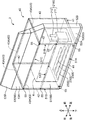
- FIG. 3 is a perspective view schematically showing a structure viewed from the rear of the hydrogen gas supply unit 2.
- the hydrogen gas supply unit 2 is a device for supplying the dispenser 11 with hydrogen gas compressed at a high pressure (for example, 82 MPa) in the hydrogen station 10.
- a high pressure for example, 82 MPa
- the hydrogen gas supply unit 2 has a unit main body 40 having a rectangular parallelepiped housing, and the compressor 21 and the pressure accumulator 23 which are the high-pressure gas equipment 6 in the unit main body 40.
- the high-pressure gas piping 20 is accommodated, respectively. 2 and 3, the high-pressure gas pipe 20 (FIG. 1) is omitted.
- the unit main body 40 includes a base plate 41, a plurality of (four) pillars 42 erected with respect to the base plate 41, and a beam 43 spanned between adjacent pillars 42.
- the housing structure is assembled with each other.
- the base plate 41 constitutes the lower surface of the unit main body 40 and is firmly fixed to the ground in the site of the hydrogen station 10 with cement or the like.
- the base plate 41 has a rectangular outer shape, and is configured by assembling a plurality of H-shaped steels.
- a compressor 21 and a pressure accumulator 23 are fixed to the H-shaped steel.
- the pillars 42 are made of, for example, H-shaped steel, and are respectively provided at the four corners of the base plate 41 at intervals.
- the column 42 has a lower end fixed to the base plate 41 and extends vertically upward with respect to the main surface of the base plate 41.
- the beam 43 is made of H-section steel like the column 42.
- the beam 43 is bridged between adjacent columns 42 so as to be parallel to the main surface of the base plate 41.
- the beam 43 includes an intermediate beam 43 ⁇ / b> B provided substantially at the center in the height direction of the column 42, and four ceiling beams 43 ⁇ / b> A provided at the top of the column 42.
- the ceiling beam 43 ⁇ / b> A constitutes a frame body having substantially the same size and shape as the rectangular shape of the base plate 41.
- the unit main body 40 constitutes a rectangular parallelepiped frame body by the base plate 41, the column 42 and the beam 43. And the steel plate panel (not shown) for soundproofing is attached in the upper surface of the said frame, the front surface, the right side surface, and the left side surface. This panel may be provided with a maintenance door or the like. An apparatus cooling cooler (not shown) or the like may be installed on the upper surface of the unit main body 40.
- the frame structure of the unit main body 40 is not limited to this, and may be a structure in which another pillar 42 or beam 43 is provided in the structure shown in FIGS. 2 and 3.
- the hydrogen gas supply unit 2 includes the compressor 21, the pressure accumulator 23, and the high pressure gas pipe 20, which are the high pressure gas equipment 6, accommodated in the unit main body 40. Since the high-pressure hydrogen gas handled in such a high-pressure gas facility 6 is a combustible gas that causes a strong impact by explosion, safety measures are required to prevent the impact from reaching the outside of the hydrogen station 10 site. . On the other hand, the hydrogen gas supply unit 2 is provided with a barrier 50 having sufficient durability against the explosion of hydrogen gas. Hereinafter, the structure of the barrier 50 will be described in detail.
- the barrier 50 constitutes a part of the hydrogen gas supply unit 2 and is made of a steel plate having a structure that can sufficiently withstand the impact of hydrogen gas explosion. Specifically, for example, the barrier 50 has a thickness of 5.00 mm as defined by a thickness of 6 mm or more (JIS G3193 (2008) (shape / dimension / mass of hot-rolled steel and steel strip and tolerance thereof).
- a steel plate having a thickness tolerance of ⁇ 0.60 mm for a steel plate having a width of less than 6.30 mm and a width of 1600 mm or more and less than 2000 mm, or a steel plate having a thickness of 3.2 mm or more and an equilateral mountain shape of 30 ⁇ 30 mm or more Steel is reinforced by welding at intervals of 40 cm or less in length and width.
- the barrier 50 has a height of 2 m or more and is provided with barrier beams (supports) 54 and 59 with an interval of 1.8 m or less.
- the standard of the barrier 50 that can withstand the impact caused by the explosion of hydrogen gas is stipulated in the general standard for high-pressure gas safety regulations in Japan.
- the barrier 50 is attached so as to cover the rear surface of the unit main body 40, and has a plate shape surrounding the outer periphery of the rear side of the high-pressure gas facility 6. Specifically, as shown by a two-dot chain line in FIG. 3, when a rectangular parallelepiped virtual space that accommodates the compressor 21, the accumulator 23, and the high-pressure gas pipe (not shown) is used as the high-pressure gas facility 6.
- the barrier 50 has a width in the left-right direction and a height in the up-down direction larger than that of the space, and covers the entire space. For this reason, as shown in FIG. 3, when the hydrogen gas supply unit 2 is viewed from the rear, the high-pressure gas facility 6 is completely shielded by the barrier 50.
- the barrier 50 is a rectangular barrier main body 51 along the rear surface of the unit main body 40, a barrier side 52 extending horizontally from the left end of the barrier main body 51, and extending upward from the upper end of the barrier main body 51. And an upper barrier portion 53.
- the barrier side portion 52 extends leftward from the left side surface of the unit main body 40, and the barrier upper portion 53 extends above the upper surface of the unit main body 40.
- the barrier 50 has the barrier side part 52 and the barrier upper part 53 as a part extended outside the upper surface and side surface of the unit main body 40. Thereby, the noise resulting from operation
- the barrier side portion 52 is joined to the barrier main body 51 by welding.
- the barrier side portion 52 includes a horizontal portion 52A extending horizontally from the left end of the barrier body 51, and an extending portion 52B connected to the horizontal portion 52A and extending forward from the end portion of the horizontal portion 52A.
- the extending portion 52 ⁇ / b> B is provided so as to cover the rear portion of the left side surface of the unit main body 40.
- the barrier 50 may be a single member, or may be constituted by a plurality of members that can be stacked or divided.
- the barrier upper part 53 is fixed to the barrier main body 51 and the barrier side part 52 by fastening members such as bolts.
- the barrier upper portion 53 includes a vertical portion 53A that extends vertically from the upper end of the barrier body 51, and an inclined portion 53B that is connected to the vertical portion 53A and is inclined forward at a certain angle.
- the inclined portion 53B is provided so as to cover the rear portion of the upper surface of the unit body 40. Note that the extending portion 52B and the inclined portion 53B may be omitted.
- the barrier side portion 52 has a steel plate barrier panel 59A and two barrier beams 59 fixed by welding or the like at a certain interval in the barrier panel 59A.
- the barrier upper portion 53 also includes a steel-made barrier panel 57 and a plurality (four) of barrier beams 54 joined by welding at a certain interval in the barrier panel 57.
- a columnar support member 58 is joined to the upper barrier portion 53 by welding, and the lower end of the support member 58 is positioned on the upper surface of the unit main body 40.
- the barrier body 51 also functions as a panel attached to the rear surface of the unit body 40, and a maintenance door or the like can be provided on the panel. Further, the panel constituting the barrier body 51 may be a single panel or a plurality of panels that can be stacked or divided.
- the barrier 50 has a part to be supported by the base plate 41.
- the barrier body 51 includes a lower end portion 51A fixed to the base plate 41, two side end portions 51B fixed to the two rear pillars 42, and an upper end portion fixed to the ceiling beam 43A. 51C and a central portion 51D fixed to the intermediate beam 43B.
- the barrier main body 51 is fixed to the base plate 41, the column 42, the ceiling beam 43A, and the intermediate beam 43B, for example, by fastening members such as bolts. That is, in the barrier body 51, bolt holes 55 for inserting bolts are formed in the lower end portion 51A, the side end portion 51B, the upper end portion 51C, and the central portion 51D as parts to be supported by the base plate 41, respectively.
- the method of fixing the barrier body 51 is not particularly limited, and may be fixed by joining to the base plate 41, the column 42, and the beam 43 by welding, for example.
- the hydrogen gas supply unit 2 has a structure in which the barrier 50 is directly supported by the base plate 41 by fixing the barrier 50 to the base plate 41.
- the hydrogen gas supply unit 2 has a structure in which the unit main body 40 and the barrier 50 are integrated. For this reason, it is not necessary to construct a barrier separately from the hydrogen gas supply unit 2 in the site of the hydrogen station 10. Therefore, it is not necessary to install the hydrogen gas supply unit 2 near an existing barrier, and the installation location of the hydrogen gas supply unit 2 can be selected more freely while ensuring safety. Further, by directly fixing the barrier 50 to the base plate 41, the barrier 50 can be more firmly fixed to the ground.
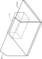
- FIG. 4 schematically shows a state in which the hydrogen gas supply unit 2 is installed in the premises 72 of the hydrogen station. 4 indicates the vertical plane of the site boundary 71, which is the boundary between the site 72 and the site 73, and the hydrogen gas supply unit 2 has a barrier 50 as shown in FIG. It is installed in a state facing the 71 side.
- the high-pressure gas facility 6 may take measures for ensuring safety when installed. It is defined in the regulations. Specifically, the high-pressure gas facility 6 needs to be installed at a position having a distance of 8 m or more with respect to the site boundary 71. If this is not possible, it is necessary to shield the range where the distance from the outer surface of the high-pressure gas facility 6 to the site boundary 71 is less than 8 m with a barrier that meets the criteria stipulated in the regulations (general high-pressure gas security in Japan). Rule relationship example criteria).
- a barrier 50 that satisfies the same standard is attached to the rear surface of the unit body 40.
- the outer surface of the high-pressure gas facility 6 A range in which the distance from the site boundary 71 is less than 8 m can be blocked by the barrier 50.
- the distances L2 and L3 between the outer surface of the high-pressure gas facility 6 and the site boundary 71 are 8 m or more as shown by the dotted line in FIG.
- the hydrogen gas supply unit 2 (combustible gas supply unit) is for supplying compressed hydrogen gas (combustible gas) to the dispenser 11.
- the hydrogen gas supply unit 2 includes a high-pressure gas facility 6 (compressor 21, accumulator 23, and high-pressure gas pipe 20) that handles compressed hydrogen gas, a base plate 41 on which the high-pressure gas facility 6 is installed, and a high-pressure gas. And a barrier 50 that is supported by the base plate 41 so as to surround the outer periphery of the facility 6 and withstands an impact caused by an explosion of hydrogen gas.
- the outer periphery of the high-pressure gas facility 6 that handles the compressed high-pressure hydrogen gas is surrounded by a barrier 50. For this reason, the impact caused by the explosion of hydrogen gas can be reduced by the barrier 50, and the impact can be prevented from reaching outside the site of the hydrogen station 10. Thereby, the safety of the hydrogen station 10 can be ensured.
- the hydrogen gas supply unit 2 has a structure in which the barrier 50 is supported by the base plate 41. For this reason, the installation location of the hydrogen gas supply unit 2 is not restricted by the existing barrier in the site 72 as in the prior art, and the installation location of the hydrogen gas supply unit 2 can be more freely secured while ensuring safety. You can choose. Therefore, according to the hydrogen gas supply unit 2, it is possible to ensure the safety of the hydrogen station 10 and to further reduce the restrictions on the installation location in the site 72.
- the barrier 50 is made of a steel plate. Thereby, compared with the case where the barrier made from a reinforced concrete or a concrete block is used, the barrier 50 can be reduced in weight and the transfer of the hydrogen gas supply unit 2 becomes easier.
- the base plate 41 may be fixed to the ground G of the premises 72 of the hydrogen station 10.
- the barrier 50 may be fixed to the base plate 41. Thereby, the barrier 50 can be directly supported by the base plate 41 by fixing the barrier 50 to the base plate 41 fixed to the ground G in the site 72. Thereby, the barrier 50 can be fixed more firmly.
- the hydrogen gas supply unit 2 includes a plurality of columns 42 erected with respect to the base plate 41 and beams 43 laid across the plurality of columns 42.
- the barrier 50 is fixed to the column 42 and the beam 43. Thereby, by fixing the barrier 50 not only to the base plate 41 but also to the pillar 42 and the beam 43, the barrier 50 can be fixed more firmly.
- the base plate 41, the column 42, and the beam 43 constitute a unit main body 40 having a casing structure.
- the high-pressure gas facility 6 is accommodated in the unit main body 40.
- the barrier 50 covers a rear surface, which is one side surface of the unit main body 40, and includes a barrier side portion 52 and a barrier upper portion 53 that are portions extending outward from the upper surface and the side surface of the unit main body 40.
- the barrier 50 is a barrier constituting a part of the hydrogen gas supply unit 2 including the high-pressure gas facility 6 that handles the compressed hydrogen gas, and has a shape surrounding the outer periphery of the high-pressure gas facility 6. It has a part for being supported by the base plate 41 on which the equipment 6 is installed.
- the barrier 50 by surrounding the outer periphery of the high-pressure gas facility 6 with the barrier 50, the impact of the hydrogen gas explosion can be reduced, and the safety of the hydrogen station 10 can be ensured. Further, by supporting the barrier 50 by the base plate 41, the installation location of the hydrogen gas supply unit 2 is not restricted by the existing barrier in the premises 72 as in the prior art, and hydrogen is secured while ensuring safety. The installation location of the gas supply unit 2 can be selected more freely. Therefore, according to the barrier 50, the safety of the hydrogen station 10 can be ensured, and restrictions on the installation location of the hydrogen gas supply unit 2 in the site 72 can be further reduced.
- the barrier 50 may be made of, for example, reinforced concrete, or may be made of a concrete block.
- reinforced concrete reinforcing bars with a diameter of 9 mm or more are arranged vertically and horizontally at intervals of 40 cm or less, particularly the reinforcing bars at the corners are securely bound, the thickness is 12 cm or more, and the height is 2 m or more. It is preferable to use one.
- a concrete block it is preferable to use the following blocks.
- reinforcing bars with a diameter of 9 mm or more are arranged vertically and horizontally at intervals of 40 cm or less, especially the reinforcing bars at the corners are securely bound, and the block cavity is filled with concrete mortar, and the thickness is 15 cm or more The height is 2 m or more.
- the standards for such reinforced concrete barriers and concrete block barriers are also stipulated in the general high pressure gas safety regulation example standards in Japan.
- the present invention is not limited to this.
- both the barrier side portion 52 and the barrier upper portion 53 may be omitted, or one of them may be omitted.
- the present invention is not limited to this.
- an extending portion 44 that extends rearward from the rear surface of the unit main body 40 in the ceiling beam 43 ⁇ / b> A may be provided, and the barrier 50 may be fixed to the extending portion 44.
- the barrier 50 is not fixed to the base plate 41 but is indirectly supported to the base plate 41 via the extending portion 44 and the column 42 of the ceiling beam 43A. Further, the barrier 50 may be fixed only to the column 42 and indirectly supported to the base plate 41 via the column 42.
- the present invention is not limited to this.
- the base plate 41 may be extended rearward, and the barrier 50 may be fixed to the extended portion 41 ⁇ / b> A.
- the barrier 50 is not fixed to the column 42 and the beam 43, but similarly, the effect of reducing the impact due to the explosion of hydrogen gas can be obtained.
- the barrier 50 may surround the outer periphery of the front side of the high-pressure gas facility 6 by being provided on the front side of the unit main body 40, or may be provided on the left and right side surfaces of the unit main body 40. You may surround the outer periphery. That is, the barrier 50 is not limited to enclosing only one outer peripheral portion of the high-pressure gas facility 6, and can be appropriately changed in design so as to enclose a portion that needs to be shielded. This is determined so that the barrier 50 is located between the outer surface of the high-pressure gas facility 6 and the site boundary 71 in consideration of the relationship between the place where the hydrogen gas supply unit 2 is installed and the site boundary 71.
- the unit main body 40 is configured only by a base plate 41, the high pressure gas facility 6 is installed on the base plate 41, and the barrier 50 is formed on the base plate 41 so as to surround the outer periphery of the high pressure gas facility 6. It may be fixed.
- the hydrogen gas supply unit 2 has been described as an example of the combustible gas supply unit, but the present invention is not limited to this. That is, the combustible gas supply unit of the present invention can be applied to a unit that handles other combustible gases such as hydrocarbon gases such as methane, propane, and acetylene in addition to hydrogen gas.
- hydrocarbon gases such as methane, propane, and acetylene
Landscapes
- Engineering & Computer Science (AREA)
- Architecture (AREA)
- Mechanical Engineering (AREA)
- General Engineering & Computer Science (AREA)
- Business, Economics & Management (AREA)
- Emergency Management (AREA)
- Environmental & Geological Engineering (AREA)
- Civil Engineering (AREA)
- Structural Engineering (AREA)
- Filling Or Discharging Of Gas Storage Vessels (AREA)
- Buildings Adapted To Withstand Abnormal External Influences (AREA)
Abstract
Description
まず、本発明の実施形態に係る可燃性ガス供給ユニット及び障壁の概要について説明する。
以下、図面に基づいて、本発明の実施形態に係る可燃性ガス供給ユニット及び障壁について詳細に説明する。
まず、本発明の一実施形態に係る可燃性ガス供給ユニットである水素ガス供給ユニット2を備えた水素ステーション10の全体構成について、図1を参照して説明する。水素ステーション10は、燃料電池車である車両9に燃料の水素ガスを充填するための施設である。水素ステーション10は、高圧(例えば82MPa)に圧縮された水素ガス(可燃性ガス)を取り扱う高圧ガス設備6を有する水素ガス供給ユニット2(可燃性ガス供給ユニット)と、水素ガス供給ユニット2から供給された高圧水素ガスを車両9に充填するためのディスペンサ11と、を有する。
次に、上記水素ガス供給ユニット2の詳細な構造について、図2及び図3を参照して説明する。図2は、水素ガス供給ユニット2の前方から見た構造を模式的に示す斜視図である。図3は、水素ガス供給ユニット2の後方から見た構造を模式的に示す斜視図である。
障壁50は、水素ガス供給ユニット2の一部を構成するものであり、水素ガスの爆発による衝撃に十分に耐える構造を有する鋼板により構成されている。具体的には、障壁50は、例えば、厚さが6mm以上(JIS G3193(2008) (熱間圧延鋼材及び鋼帯の形状・寸法・質量及びその許容差)において規定される厚さ5.00mm以上6.30mm未満、幅1600mm以上2000mm未満の鋼板に対する厚さの許容差±0.60mmを満たすもの)の鋼板、又は厚さが3.2mm以上の鋼板であって30×30mm以上の等辺山形鋼を縦、横40cm以下の間隔に溶接により取り付けて補強したものである。また障壁50は、高さが2m以上であり、1.8m以下の間隔を空けて障壁梁(支柱)54,59が設けられたものである。このように水素ガスの爆発による衝撃に耐える障壁50の基準については、日本国の一般高圧ガス保安規則関係例示基準に定められている。
次に、上記水素ガス供給ユニット2及び障壁50の特徴及びその作用効果について説明する。
上記実施形態では、障壁50が鋼板により構成される場合について説明したが、これに限定されない。障壁50は、例えば鉄筋コンクリートにより構成されるものでもよいし、コンクリートブロックにより構成されるものでもよい。鉄筋コンクリートを用いる場合には、直径が9mm以上の鉄筋が縦、横40cm以下の間隔で配筋され、特に隅部の鉄筋が確実に結束され、厚さが12cm以上であり、高さ2m以上のものを用いることが好ましい。またコンクリートブロックを用いる場合には、以下のようなブロックを用いることが好ましい。このブロックは、直径が9mm以上の鉄筋が縦、横40cm以下の間隔に配筋され、特に隅部の鉄筋が確実に結束され、ブロックの空洞部にコンクリートモルタルが充填され、厚さが15cm以上であり、高さが2m以上のものである。このような鉄筋コンクリート製障壁及びコンクリートブロック製障壁の基準についても、日本国の一般高圧ガス保安規則関係例示基準に定められている。
Claims (10)
- 圧縮された可燃性ガスをディスペンサに供給するための可燃性ガス供給ユニットであって、
圧縮された可燃性ガスを取り扱う高圧ガス設備と、
前記高圧ガス設備が設置された台板と、
前記高圧ガス設備の外周の少なくとも一部を囲うように前記台板に支持された障壁と、を備えることを特徴とする、可燃性ガス供給ユニット。 - 前記障壁は、鋼板により構成されていることを特徴とする、請求項1に記載の可燃性ガス供給ユニット。
- 前記可燃性ガスは、水素ガスである、請求項1又は2に記載の可燃性ガス供給ユニット。
- 前記台板は、地面に固定され、
前記障壁は、前記台板に固定されていることを特徴とする、請求項1又は2に記載の可燃性ガス供給ユニット。 - 前記台板は、地面に固定され、
前記障壁は、前記台板に固定されていることを特徴とする、請求項3に記載の可燃性ガス供給ユニット。 - 前記台板に対して立設された柱をさらに備え、
前記障壁は、前記柱に固定されていることを特徴とする、請求項4に記載の可燃性ガス供給ユニット。 - 前記台板に対して立設された柱をさらに備え、
前記障壁は、前記柱に固定されていることを特徴とする、請求項5に記載の可燃性ガス供給ユニット。 - 前記柱は、互いに間隔を空けて複数設けられ、
前記可燃性ガス供給ユニットは、複数の前記柱間に架け渡された梁をさらに備え、
前記障壁は、前記梁に固定されていることを特徴とする、請求項6に記載の可燃性ガス供給ユニット。 - 前記台板、前記柱及び前記梁は、筐体構造のユニット本体を構成し、
前記高圧ガス設備は、前記ユニット本体内に収容され、
前記障壁は、前記ユニット本体の少なくとも1つの側面を覆い、且つ、前記ユニット本体の上面又は側面よりも外側に延びる部位を有する、請求項8に記載の可燃性ガス供給ユニット。 - 圧縮された可燃性ガスを取り扱う高圧ガス設備を備えた可燃性ガス供給ユニットの一部を構成する障壁であって、
前記高圧ガス設備の外周の少なくとも一部を囲う形状を有し、前記高圧ガス設備が設置された台板に支持されるための部位を有することを特徴とする、障壁。
Priority Applications (5)
| Application Number | Priority Date | Filing Date | Title |
|---|---|---|---|
| KR1020187026427A KR102134731B1 (ko) | 2016-02-29 | 2017-02-21 | 가연성 가스 공급 유닛 및 장벽 |
| CN201780008890.2A CN108496038A (zh) | 2016-02-29 | 2017-02-21 | 可燃性气体供给组件以及屏障 |
| US16/072,853 US10704284B2 (en) | 2016-02-29 | 2017-02-21 | Combustible gas supply unit and barrier |
| CA3011681A CA3011681C (en) | 2016-02-29 | 2017-02-21 | Steel plate barrier for protection against explosion in a gas supply unit |
| EP17759738.2A EP3396229A4 (en) | 2016-02-29 | 2017-02-21 | SUPPLY UNIT FOR COMBUSTIBLE GAS AND BARRIER |
Applications Claiming Priority (2)
| Application Number | Priority Date | Filing Date | Title |
|---|---|---|---|
| JP2016037125A JP6659401B2 (ja) | 2016-02-29 | 2016-02-29 | 可燃性ガス供給ユニット及び障壁 |
| JP2016-037125 | 2016-02-29 |
Publications (1)
| Publication Number | Publication Date |
|---|---|
| WO2017150272A1 true WO2017150272A1 (ja) | 2017-09-08 |
Family
ID=59743829
Family Applications (1)
| Application Number | Title | Priority Date | Filing Date |
|---|---|---|---|
| PCT/JP2017/006344 Ceased WO2017150272A1 (ja) | 2016-02-29 | 2017-02-21 | 可燃性ガス供給ユニット及び障壁 |
Country Status (7)
| Country | Link |
|---|---|
| US (1) | US10704284B2 (ja) |
| EP (1) | EP3396229A4 (ja) |
| JP (1) | JP6659401B2 (ja) |
| KR (1) | KR102134731B1 (ja) |
| CN (1) | CN108496038A (ja) |
| CA (1) | CA3011681C (ja) |
| WO (1) | WO2017150272A1 (ja) |
Families Citing this family (7)
| Publication number | Priority date | Publication date | Assignee | Title |
|---|---|---|---|---|
| CN207316168U (zh) | 2017-05-05 | 2018-05-04 | 卡瓦尼亚集团股份公司 | 一种用于将燃气输送至器具的燃气站 |
| KR102122874B1 (ko) * | 2017-07-28 | 2020-06-15 | 가부시키가이샤 고베 세이코쇼 | 가연성 가스 공급 유닛 및 수소 스테이션 |
| JP6810015B2 (ja) * | 2017-11-02 | 2021-01-06 | 株式会社神戸製鋼所 | ガス供給装置 |
| JP7057100B2 (ja) * | 2017-11-16 | 2022-04-19 | 株式会社神戸製鋼所 | ガス供給装置 |
| KR102120965B1 (ko) * | 2019-04-19 | 2020-06-09 | (주)한엑스 | 서로 다른 냉각 공간을 제공해주는 상용차량용 냉장고 |
| KR102228698B1 (ko) * | 2020-05-26 | 2021-03-18 | 주식회사 케이씨 | 가스 공급 장치 |
| FR3121608B1 (fr) * | 2021-04-07 | 2023-04-14 | Air Liquide | Barrière de protection pour un équipement industriel |
Citations (9)
| Publication number | Priority date | Publication date | Assignee | Title |
|---|---|---|---|---|
| JPS53142741U (ja) * | 1977-04-16 | 1978-11-10 | ||
| JPS55124535A (en) * | 1979-03-19 | 1980-09-25 | Nippon Oil & Fats Co Ltd | Detonation chamber |
| JPS5622885A (en) * | 1979-08-02 | 1981-03-04 | Taketomi Ogawa | Nonenvironmental pollution ground type seconddclass powder magazine and moving type powder magazine used as single warehouse* unting type mechanism powder magazine and unitingsingle warehouse |
| JPS6041448U (ja) * | 1983-08-30 | 1985-03-23 | 小川 健富 | 柱を外壁側に設けた鋼材地上式2級火薬庫 |
| JPH06211303A (ja) * | 1993-01-19 | 1994-08-02 | Nippon Sanso Kk | ガス充填方法及び設備 |
| JPH07101316A (ja) * | 1993-09-30 | 1995-04-18 | Mazda Motor Corp | 給水素スタンド |
| JP2008057185A (ja) * | 2006-08-30 | 2008-03-13 | Tokiko Techno Kk | 水素貯蔵建屋 |
| JP4310519B2 (ja) | 2004-07-06 | 2009-08-12 | 清水建設株式会社 | 防護壁 |
| JP2016199917A (ja) * | 2015-04-10 | 2016-12-01 | 株式会社竹中工務店 | 防護構造 |
Family Cites Families (7)
| Publication number | Priority date | Publication date | Assignee | Title |
|---|---|---|---|---|
| US6732769B2 (en) * | 2001-09-27 | 2004-05-11 | Gnc Galileo S.A. | Modular compressed natural gas (CNG) station and method for avoiding fire in such station |
| CN1219138C (zh) * | 2003-12-11 | 2005-09-14 | 中国人民解放军理工大学工程兵工程学院 | 增强爆破安全挡波墙的构筑方法 |
| GB0525727D0 (en) * | 2005-12-17 | 2006-01-25 | Secr Defence | A barrier |
| JP4898309B2 (ja) | 2006-06-07 | 2012-03-14 | 三菱重工業株式会社 | コンテナの構造 |
| CN201909177U (zh) * | 2010-11-05 | 2011-07-27 | 梅思安(中国)安全设备有限公司 | 单工位简易防爆充气箱 |
| KR101380644B1 (ko) * | 2011-12-23 | 2014-04-08 | 삼성중공업 주식회사 | 가스연료 추진선박 |
| US20130233388A1 (en) * | 2012-03-06 | 2013-09-12 | General Electric Company | Modular compressed natural gas system |
-
2016
- 2016-02-29 JP JP2016037125A patent/JP6659401B2/ja not_active Expired - Fee Related
-
2017
- 2017-02-21 US US16/072,853 patent/US10704284B2/en not_active Expired - Fee Related
- 2017-02-21 CN CN201780008890.2A patent/CN108496038A/zh active Pending
- 2017-02-21 KR KR1020187026427A patent/KR102134731B1/ko not_active Expired - Fee Related
- 2017-02-21 WO PCT/JP2017/006344 patent/WO2017150272A1/ja not_active Ceased
- 2017-02-21 CA CA3011681A patent/CA3011681C/en active Active
- 2017-02-21 EP EP17759738.2A patent/EP3396229A4/en not_active Withdrawn
Patent Citations (9)
| Publication number | Priority date | Publication date | Assignee | Title |
|---|---|---|---|---|
| JPS53142741U (ja) * | 1977-04-16 | 1978-11-10 | ||
| JPS55124535A (en) * | 1979-03-19 | 1980-09-25 | Nippon Oil & Fats Co Ltd | Detonation chamber |
| JPS5622885A (en) * | 1979-08-02 | 1981-03-04 | Taketomi Ogawa | Nonenvironmental pollution ground type seconddclass powder magazine and moving type powder magazine used as single warehouse* unting type mechanism powder magazine and unitingsingle warehouse |
| JPS6041448U (ja) * | 1983-08-30 | 1985-03-23 | 小川 健富 | 柱を外壁側に設けた鋼材地上式2級火薬庫 |
| JPH06211303A (ja) * | 1993-01-19 | 1994-08-02 | Nippon Sanso Kk | ガス充填方法及び設備 |
| JPH07101316A (ja) * | 1993-09-30 | 1995-04-18 | Mazda Motor Corp | 給水素スタンド |
| JP4310519B2 (ja) | 2004-07-06 | 2009-08-12 | 清水建設株式会社 | 防護壁 |
| JP2008057185A (ja) * | 2006-08-30 | 2008-03-13 | Tokiko Techno Kk | 水素貯蔵建屋 |
| JP2016199917A (ja) * | 2015-04-10 | 2016-12-01 | 株式会社竹中工務店 | 防護構造 |
Also Published As
| Publication number | Publication date |
|---|---|
| JP2017155765A (ja) | 2017-09-07 |
| KR102134731B1 (ko) | 2020-07-16 |
| EP3396229A1 (en) | 2018-10-31 |
| CN108496038A (zh) | 2018-09-04 |
| CA3011681C (en) | 2021-05-25 |
| US20180371782A1 (en) | 2018-12-27 |
| JP6659401B2 (ja) | 2020-03-04 |
| CA3011681A1 (en) | 2017-09-08 |
| KR20180114922A (ko) | 2018-10-19 |
| EP3396229A4 (en) | 2019-08-14 |
| US10704284B2 (en) | 2020-07-07 |
Similar Documents
| Publication | Publication Date | Title |
|---|---|---|
| WO2017150272A1 (ja) | 可燃性ガス供給ユニット及び障壁 | |
| JP6473033B2 (ja) | ガス供給システムおよび水素ステーション | |
| KR102130606B1 (ko) | 가스 공급 장치 | |
| US9534370B2 (en) | Assembly comprising an engine | |
| JP4291267B2 (ja) | コールドボックス金属板ジャケット | |
| JP2013024287A (ja) | 水素ガス充填装置 | |
| JP7083660B2 (ja) | 可燃性ガス供給ユニット及び水素ステーション | |
| WO2015125585A1 (ja) | ガス供給システムおよび水素ステーション | |
| CN109307149B (zh) | 可燃性气体供给组件以及加氢站 | |
| WO2016067780A1 (ja) | 水素ステーション | |
| JP7057100B2 (ja) | ガス供給装置 | |
| KR101403466B1 (ko) | 집속형 압축천연가스 충전 시스템 | |
| JP2005256859A (ja) | 断熱構造 | |
| JP5327645B2 (ja) | 水素関連施設における壁面構造 | |
| JP6847607B2 (ja) | 冷蔵倉庫 | |
| WO2026053514A1 (ja) | 熱源装置 | |
| JP2026050066A (ja) | 熱源装置 | |
| JP6038770B2 (ja) | 氷蓄熱ユニット | |
| JP2001304496A (ja) | Lpガス供給設備 | |
| JP2017190916A (ja) | 冷凍装置の室外ユニット |
Legal Events
| Date | Code | Title | Description |
|---|---|---|---|
| WWE | Wipo information: entry into national phase |
Ref document number: 3011681 Country of ref document: CA |
|
| WWE | Wipo information: entry into national phase |
Ref document number: 2017759738 Country of ref document: EP |
|
| ENP | Entry into the national phase |
Ref document number: 2017759738 Country of ref document: EP Effective date: 20180726 |
|
| NENP | Non-entry into the national phase |
Ref country code: DE |
|
| ENP | Entry into the national phase |
Ref document number: 20187026427 Country of ref document: KR Kind code of ref document: A |
|
| WWE | Wipo information: entry into national phase |
Ref document number: 1020187026427 Country of ref document: KR |