WO2017150625A1 - 絶縁電線、コイル及び電気・電子機器 - Google Patents
絶縁電線、コイル及び電気・電子機器 Download PDFInfo
- Publication number
- WO2017150625A1 WO2017150625A1 PCT/JP2017/008162 JP2017008162W WO2017150625A1 WO 2017150625 A1 WO2017150625 A1 WO 2017150625A1 JP 2017008162 W JP2017008162 W JP 2017008162W WO 2017150625 A1 WO2017150625 A1 WO 2017150625A1
- Authority
- WO
- WIPO (PCT)
- Prior art keywords
- insulated wire
- adhesive layer
- layer
- insulating
- resin
- Prior art date
- Legal status (The legal status is an assumption and is not a legal conclusion. Google has not performed a legal analysis and makes no representation as to the accuracy of the status listed.)
- Ceased
Links
Images



Classifications
-
- H—ELECTRICITY
- H01—ELECTRIC ELEMENTS
- H01B—CABLES; CONDUCTORS; INSULATORS; SELECTION OF MATERIALS FOR THEIR CONDUCTIVE, INSULATING OR DIELECTRIC PROPERTIES
- H01B13/00—Apparatus or processes specially adapted for manufacturing conductors or cables
- H01B13/0016—Apparatus or processes specially adapted for manufacturing conductors or cables for heat treatment
-
- H—ELECTRICITY
- H01—ELECTRIC ELEMENTS
- H01B—CABLES; CONDUCTORS; INSULATORS; SELECTION OF MATERIALS FOR THEIR CONDUCTIVE, INSULATING OR DIELECTRIC PROPERTIES
- H01B13/00—Apparatus or processes specially adapted for manufacturing conductors or cables
- H01B13/06—Insulating conductors or cables
- H01B13/065—Insulating conductors with lacquers or enamels
-
- H—ELECTRICITY
- H01—ELECTRIC ELEMENTS
- H01B—CABLES; CONDUCTORS; INSULATORS; SELECTION OF MATERIALS FOR THEIR CONDUCTIVE, INSULATING OR DIELECTRIC PROPERTIES
- H01B7/00—Insulated conductors or cables characterised by their form
- H01B7/0009—Details relating to the conductive cores
-
- H—ELECTRICITY
- H01—ELECTRIC ELEMENTS
- H01B—CABLES; CONDUCTORS; INSULATORS; SELECTION OF MATERIALS FOR THEIR CONDUCTIVE, INSULATING OR DIELECTRIC PROPERTIES
- H01B7/00—Insulated conductors or cables characterised by their form
- H01B7/02—Disposition of insulation
-
- H—ELECTRICITY
- H01—ELECTRIC ELEMENTS
- H01B—CABLES; CONDUCTORS; INSULATORS; SELECTION OF MATERIALS FOR THEIR CONDUCTIVE, INSULATING OR DIELECTRIC PROPERTIES
- H01B7/00—Insulated conductors or cables characterised by their form
- H01B7/02—Disposition of insulation
- H01B7/0208—Cables with several layers of insulating material
- H01B7/0225—Three or more layers
-
- H—ELECTRICITY
- H01—ELECTRIC ELEMENTS
- H01F—MAGNETS; INDUCTANCES; TRANSFORMERS; SELECTION OF MATERIALS FOR THEIR MAGNETIC PROPERTIES
- H01F5/00—Coils
-
- H—ELECTRICITY
- H01—ELECTRIC ELEMENTS
- H01F—MAGNETS; INDUCTANCES; TRANSFORMERS; SELECTION OF MATERIALS FOR THEIR MAGNETIC PROPERTIES
- H01F5/00—Coils
- H01F5/02—Coils wound on non-magnetic supports, e.g. formers
-
- H—ELECTRICITY
- H01—ELECTRIC ELEMENTS
- H01F—MAGNETS; INDUCTANCES; TRANSFORMERS; SELECTION OF MATERIALS FOR THEIR MAGNETIC PROPERTIES
- H01F5/00—Coils
- H01F5/06—Insulation of windings
-
- H—ELECTRICITY
- H02—GENERATION; CONVERSION OR DISTRIBUTION OF ELECTRIC POWER
- H02K—DYNAMO-ELECTRIC MACHINES
- H02K15/00—Processes or apparatus specially adapted for manufacturing, assembling, maintaining or repairing of dynamo-electric machines
- H02K15/10—Applying solid insulation to windings, stators or rotors, e.g. applying insulating tapes
- H02K15/105—Applying solid insulation to windings, stators or rotors, e.g. applying insulating tapes to the windings
-
- H—ELECTRICITY
- H02—GENERATION; CONVERSION OR DISTRIBUTION OF ELECTRIC POWER
- H02K—DYNAMO-ELECTRIC MACHINES
- H02K3/00—Details of windings
- H02K3/04—Windings characterised by the conductor shape, form or construction, e.g. with bar conductors
- H02K3/12—Windings characterised by the conductor shape, form or construction, e.g. with bar conductors arranged in slots
-
- H—ELECTRICITY
- H02—GENERATION; CONVERSION OR DISTRIBUTION OF ELECTRIC POWER
- H02K—DYNAMO-ELECTRIC MACHINES
- H02K3/00—Details of windings
- H02K3/30—Windings characterised by the insulating material
-
- H—ELECTRICITY
- H02—GENERATION; CONVERSION OR DISTRIBUTION OF ELECTRIC POWER
- H02K—DYNAMO-ELECTRIC MACHINES
- H02K3/00—Details of windings
- H02K3/32—Windings characterised by the shape, form or construction of the insulation
-
- H—ELECTRICITY
- H02—GENERATION; CONVERSION OR DISTRIBUTION OF ELECTRIC POWER
- H02K—DYNAMO-ELECTRIC MACHINES
- H02K3/00—Details of windings
- H02K3/32—Windings characterised by the shape, form or construction of the insulation
- H02K3/34—Windings characterised by the shape, form or construction of the insulation between conductors or between conductor and core, e.g. slot insulation
-
- H—ELECTRICITY
- H01—ELECTRIC ELEMENTS
- H01B—CABLES; CONDUCTORS; INSULATORS; SELECTION OF MATERIALS FOR THEIR CONDUCTIVE, INSULATING OR DIELECTRIC PROPERTIES
- H01B7/00—Insulated conductors or cables characterised by their form
- H01B7/08—Flat or ribbon cables
Definitions
- the present invention relates to an insulated wire, a coil, and an electric / electronic device.
- Inverter-related equipment such as coils for electric and electronic equipment such as high-speed switching elements, inverter motors, transformers, etc., as magnet wires, insulated wires made of so-called enameled wires, layers made of enamel resin, and enamels
- magnet wires insulated wires made of so-called enameled wires, layers made of enamel resin, and enamels
- An insulated wire having a multilayer coating layer including a coating layer made of a resin different from the resin is used.
- Patent Document 1 discloses a technique in which an insulating paper is disposed in a coil housing groove formed in a stator core of a rotary electric motor, and the coil is fixed to the coil housing groove by a varnish, and the coil and the stator core are fixed while being insulated.
- Patent Document 2 discloses a prepreg sheet as a technique for preventing contact between a stator core or a rotor core of an automobile drive motor and a conductor coil.
- Patent Document 3 discloses a technique for preventing partial discharge between adjacent coils and the like by providing an additional insulating layer in a predetermined region of a hypotenuse and a bent portion of a segment coil.
- the insulation paper may be displaced due to the insertion work of the insulated wire. Deviations in the vertical direction of the slot (motor shaft direction) or the outside of the slot (inner direction of the motor radial direction) lead to problems such as interference with the rotor.
- the thermosetting adhesive layer formed in the sheet base material is made of an epoxy resin composition
- the prepreg sheet described in Patent Document 2 has the thermosetting adhesion when used in a high temperature environment (for example, 200 ° C. or more). There is a problem that the layer is softened and the adhesiveness is lost.
- the required performance of the insulated wire differs between the portion inserted into the slot (straight line portion) and the portion outside the slot (bending portion, welded portion). In order to obtain a high partial discharge starting voltage in the bent part, when an additional insulating layer is provided as described in Patent Document 3, it is necessary to perform positioning after bending of the winding. The process becomes complicated.
- the present invention relates to an insulated wire having an insulating paper with an adhesive layer interposed therebetween, and the insulating paper is less likely to be displaced when the insulated wire is inserted into a slot of a stator core or during bending, and the partial discharge of the bent portion
- An object is to provide an insulated wire having a high start voltage (PDIV) and excellent heat resistance, a coil using the insulated wire, and an electric / electronic device using the coil.
- PDIV high start voltage
- the inventors have provided an insulating layer on the outer periphery of a conductor having a rectangular cross section, an adhesive layer having a specific thickness, and the resin constituting the adhesive layer does not have a melting point and has a tensile elastic modulus at 250 ° C. Is provided on the outer periphery of the insulating layer, and even if the insulated wire having the insulating paper on the outer periphery of the adhesive layer is at a high temperature (for example, 200 ° C.), the insulating paper is the insulating layer.
- An insulated wire having an insulating layer on the outer periphery of a conductor having a rectangular cross section, an adhesive layer on the outer periphery of the insulating layer, and insulating paper on the outer periphery of the adhesive layer,
- the thickness of the adhesive layer is 2 to 50 ⁇ m
- the resin constituting the adhesive layer does not have a melting point
- the tensile elastic modulus at 250 ° C. is 0.9 ⁇ 10 7 to 1.2 ⁇ 10 8 Pa. Insulated wire.
- the adhesive layer contains at least one resin selected from the group consisting of polyethersulfone, polyphenylsulfone, and polyetherimide as the resin constituting the adhesive layer.
- Insulated wires [3] The insulated wire according to [1] or [2], which has an adhesive layer on an outer periphery of the insulating paper. [4] A coil comprising the insulated wire according to any one of [1] to [3]. [5] An electric / electronic device having the coil according to [4].
- a numerical range represented by using “to” means a range including numerical values described before and after that as a lower limit value and an upper limit value.
- the insulating paper is fixed to the insulating layer with a strong fixing force, and the insulating paper is not displaced when the insulated wire is inserted into the slot of the stator core, and the additional insulating layer is provided.
- the partial discharge start voltage (PDIV) of the bent portion is high, and the bending workability and heat resistance are excellent.
- the coil using the insulated wire of this invention and the electrical / electronic device using the said coil are excellent in insulation.
- FIG. 1 is a schematic cross-sectional view showing a preferred embodiment of the insulated wire of the present invention.
- FIG. 2 is a schematic cross-sectional view showing another preferred embodiment of the insulated wire of the present invention.
- FIG. 3 is a schematic cross-sectional view showing still another preferred embodiment of the insulated wire of the present invention.
- FIG. 4 is a schematic cross-sectional view showing still another preferred embodiment of the insulated wire of the present invention.
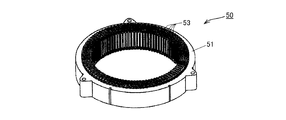
- FIG. 5 is a schematic perspective view showing a preferred form of a stator used in the electric / electronic device of the present invention.
- FIG. 6 is a schematic exploded perspective view showing a preferred form of a stator used in the electric / electronic device of the present invention.
- the insulated wire of the present invention has an insulating layer on the outer periphery of a conductor having a rectangular cross section, an adhesive layer on the outer periphery of the insulating layer, and further has insulating paper on the outer periphery of the adhesive layer.
- the insulated wire of the present invention may have an adhesive layer on the outer periphery of the insulating paper.
- a preferred insulated wire 1 of the present invention whose sectional view is shown in FIG. 1 includes a conductor 11, a resin coating layer 14 formed on the outer peripheral surface of the conductor 11, and an insulating paper 15.
- the conductor 11 has a rectangular cross section (flat rectangular shape).
- a conductor having a rectangular cross section includes a conductor having a rectangular cross section and a conductor having a square cross section.
- the resin coating layer 14 has a two-layer structure including an innermost insulating layer 12 in contact with the outer peripheral surface of the conductor 11 and an adhesive layer 13 in contact with the outer peripheral surface of the insulating layer 12.
- the total thickness of the resin coating layer 14 is preferably set to 40 to 250 ⁇ m.
- the thickness of each layer constituting the resin coating layer or the resin coating layer is determined by observing a cross section of the insulated wire perpendicular to the longitudinal axis direction using a microscope, and measuring the resin layer to be measured. Measure the shortest distance from the outer circumference of the inner layer adjacent to the conductor (or the conductor if the measurement target layer is in contact with the conductor) to the outer circumference of the measurement target layer at 16 randomly selected points and average It is a value calculated as a value.
- a preferred insulated wire 2 of the present invention whose sectional view is shown in FIG. 2 has the same configuration as the insulated wire 1 except that an adhesive layer 26 is provided on the outer periphery of the insulating paper 25.
- a preferred insulated wire 3 of the present invention whose sectional view is shown in FIG. 3 has the same configuration as the insulated wire 1 except that an insulating layer 33 is provided between the insulating layer 32 and the adhesive layer 34.
- a preferred insulated wire 4 of the present invention whose sectional view is shown in FIG. 4 has the same configuration as the insulated wire 3 except that an adhesive layer 47 is provided on the outer periphery of the insulating paper 46.
- conductors 11 and 21 used in the present invention ordinary conductors used in insulated wires can be widely used.
- metal conductors such as copper wires and aluminum wires can be used.
- it is a low oxygen copper having an oxygen content of 30 ppm or less, more preferably a low oxygen copper or oxygen free copper conductor having a oxygen content of 20 ppm or less. If the oxygen content is 30 ppm or less, when the conductor is melted with heat to prevent welding, voids due to oxygen contained in the welded portion are not generated, and the electrical resistance of the welded portion is prevented from deteriorating. The strength of the welded portion can be maintained.
- the conductors 11 and 21 used in the present invention have a rectangular cross section (flat rectangular shape).
- the rectangular conductor can increase the space factor with respect to the slots of the stator core at the time of winding, compared with a circular conductor.
- the flat rectangular conductor preferably has a shape in which chamfers (curvature radius r) are provided at four corners, as shown in FIG.
- the curvature radius r is preferably 0.6 mm or less, and more preferably 0.2 to 0.4 mm.
- the size of the conductor is not particularly limited. In the case of a flat rectangular conductor, the width (long side) is preferably 1.0 to 5.0 mm, more preferably 1.4 to 4.0 mm, and the thickness in the rectangular cross-sectional shape.
- the (short side) is preferably 0.4 to 3.0 mm, and more preferably 0.5 to 2.5 mm.
- the ratio of the width (long side) to the thickness (short side) (thickness: width) is preferably 1: 1 to 1: 4.
- the diameter is preferably 0.3 to 3.0 mm, more preferably 0.4 to 2.7 mm.
- the insulating layers 12 and 22 are preferably both layers made of a thermosetting resin (hereinafter referred to as a thermosetting resin layer).
- a layer made of resin resin Z
- it is formed of a layer formed only from resin Z and resin Z and other components (for example, a resin or additive other than resin Z). It is used to mean to include both aspects of the layer.
- the content rate of the “other components” in the layer made of the resin Z is not particularly limited as long as the target effect is not impaired, and is usually larger than 0% by mass and 10% by mass or less ( Preferably it is 5 mass% or less.
- the thermosetting resin layer means a cured resin layer, and does not mean a resin layer before curing.
- the insulating layers 12 and 22 are preferably resin layers obtained by baking and applying a thermosetting resin varnish to cause a curing reaction.
- the insulating layers 12 and 22 are preferably so-called enamel (resin) layers.
- the thermosetting resin used for the insulating layers 12 and 22 is not particularly limited.
- polyimide (PI), polyurethane, polyamideimide (PAI), polyester (PEst), polybenzimidazole, polyesterimide (PEsI), melamine examples thereof include resins and epoxy resins.
- At least one selected from the group consisting of polyimide, polyamideimide, polyester and polyesterimide is preferable, and at least one selected from the group consisting of polyimide, polyamideimide and polyester is more preferable.
- one type of thermosetting resin may be used alone, or two or more types may be used in combination.
- the polyimide that can form the insulating layers 12 and 22 is not particularly limited, and ordinary polyimides such as wholly aromatic polyimides and thermosetting aromatic polyimides can be used.
- ordinary polyimides such as wholly aromatic polyimides and thermosetting aromatic polyimides can be used.
- a polyamic acid solution obtained by reacting an aromatic tetracarboxylic dianhydride and an aromatic diamine compound in a polar solvent by a conventional method a product obtained by imidization by a heat treatment during baking is used. Can be used.
- Polyamideimide that can constitute the insulating layers 12 and 22 has a lower thermal conductivity than other resins, a high dielectric breakdown voltage, and can be baked and cured.
- Polyamideimide is not particularly limited, but it is obtained by a conventional method, for example, by directly reacting a tricarboxylic acid anhydride and a diisocyanate compound in a polar solvent, or a diamine compound is first added to a tricarboxylic acid anhydride in a polar solvent.
- a diamine compound is first added to a tricarboxylic acid anhydride in a polar solvent.
- Examples thereof include those obtained by reacting, first introducing an imide bond and then amidating with a diisocyanate compound.
- the polyester that can constitute the insulating layers 12 and 22 may be a polymer having an ester bond in the molecule and thermosetting, and is preferably a H-type polyester (HPE).
- HPE H-type polyester
- examples of such a type H polyester include those obtained by modifying a resin by adding a phenol resin or the like among aromatic polyesters and having a heat resistance class H.
- the polyesterimide which can comprise the insulating layers 12 and 22 will not be specifically limited if it is a polymer which has an ester bond and an imide bond in a molecule
- an imide bond is formed from a tricarboxylic acid anhydride and an amine compound
- an ester bond is formed from an alcohol and a carboxylic acid or an alkyl ester thereof
- the free acid group or anhydride group of the imide bond is added to the ester formation reaction.
- a polyesterimide for example, those obtained by reacting a tricarboxylic acid anhydride, a dicarboxylic acid compound or an alkyl ester thereof, an alcohol compound and a diamine compound by an ordinary method can be used.
- the thickness of the insulating layers 12 and 22 is not particularly limited, and is usually 20 to 120 ⁇ m, more preferably 40 to 100 ⁇ m.
- the insulating layers 12 and 22 are usually formed by baking and coating on the surfaces of the conductors 11 and 21. Specifically, it is preferably formed by baking and applying a varnish containing a thermosetting resin to the surfaces of the conductors 11 and 21.
- thermosetting resin used for the insulating layers 12 and 22 can be used as the thermosetting resin used for the insulating layers 12 and 22.
- the polyimide include Uimide (trade name, manufactured by Unitika), U-Varnish (trade name, manufactured by Ube Industries), and the like.
- polyamideimide include HI406 or HCI series (both trade names, manufactured by Hitachi Chemical Co., Ltd.).
- the type H polyester include Isonel 200 (trade name, manufactured by Schenectady International) and Neoheat 8242K2 (trade name, manufactured by Tohoku Paint Co., Ltd.).
- the polyester imide include Neoheat 8600A (trade name, manufactured by Tohoku Paint Co., Ltd.).
- the insulating layers 12 and 22 may have a form in which bubbles are present in the layers.
- the adhesive layers 13 and 23 can be fixed to the insulating paper in contact with the adhesive layers 13 and 23. As a result, the insulated wire can be fixed to the insulating paper.
- the adhesive layers 13 and 23 are usually subjected to a heat treatment at 250 ° C. or more in a state where the adhesive layers 13 and 23 are in contact with the insulating paper.
- the heat treatment temperature for fixing is preferably 250 to 320 ° C, more preferably 270 to 300 ° C.
- the heat treatment time for fixing is preferably 5 to 20 minutes, more preferably 10 to 15 minutes.
- the adhesive layers 13 and 23 are made of a thermoplastic resin having specific physical properties. That is, the thermoplastic resin constituting the adhesive layers 13 and 23 does not have a melting point. Since the thermoplastic resin constituting the adhesive layer does not have a melting point, the adhesive layer is hard to be hardened even if it is repeatedly exposed to high temperatures or exposed to high temperatures for a long period of time, and has a firm adhesion state to the object. It becomes possible to maintain it stably for a long time.
- “having no melting point” means that no crystal melting peak or crystallization peak is observed in a differential scanning calorimeter (DSC) measurement.
- the thermoplastic resin constituting the adhesive layers 13 and 23 has a tensile elastic modulus at 250 ° C.
- the “tensile elastic modulus at 250 ° C.” can be measured by the method described in the Examples section below.
- thermoplastic resin constituting the adhesive layers 13 and 23 is not particularly limited as long as it has the above physical properties.
- polyethersulfone (PES), polyetherimide (PEI), polyphenylene sulfide (PPS), polyethersulfone ( At least one resin selected from PESU), polyphenylsulfone (PPSU), polyetherimide (PEI), and polysulfone (PSU) can be used. It is also preferable to use a blend resin of these resins.
- the thermoplastic resin which comprises the contact bonding layers 13 and 23 contains the at least 1 sort (s) of thermoplastic resin chosen from polyethersulfone, polyphenylsulfone, and polyetherimide.
- the total content of polyethersulfone, polyphenylsulfone and polyetherimide is preferably 50% by mass or more, more preferably 70% by mass or more. 80 mass% or more is more preferable, and 90 mass% or more is especially preferable.
- the thermoplastic resin constituting the adhesive layers 13 and 23 is more preferably composed of at least one thermoplastic resin selected from polyethersulfone, polyphenylsulfone, and polyetherimide.
- the thickness of the adhesive layers 13 and 23 is not particularly limited, and is 2 to 50 ⁇ m, preferably 5 to 20 ⁇ m, from the viewpoint of satisfying both sufficient fixing force and high density (space factor) of the coil.
- Insulating paper 15 and 25 plays a role equivalent to insulating paper used in a process of forming a coil by winding a winding made of a round wire or a flat wire around a stator coil constituting a driving motor of a hybrid vehicle. Is required. For this reason, it is calculated
- the insulating paper is composed of a film and a non-woven fabric disposed on both sides of the film.
- insulating paper having high heat resistance can be obtained by selecting an aramid fiber having excellent heat resistance as the nonwoven fabric.
- Insulating paper 15 and 25 are formed as an insulating paper layer by, for example, winding an insulating paper having a predetermined width around the outer periphery a plurality of times when passing through an insulated wire having an insulating layer and an adhesive layer formed on a conductor. Is done.
- the thickness of the insulating paper layer is 10 to 600 ⁇ m, preferably about 20 to 300 ⁇ m.
- the insulating papers 15 and 25 constituting the insulated wire of the present invention may be composed of one layer of the above insulating paper.
- the insulating paper may be wound two or more times as described above to form two or more layers.
- the adhesive layer 26 may be the same as or different from the adhesive layer 23, but is preferably different.
- the adhesive layer 26 can be fixed to an object in contact with the adhesive layer 26. As a result, the insulated wire can be reliably fixed by the object.
- the heat treatment at 250 ° C. or higher is usually performed in a state where the adhesive layer 26 and the object are in contact with each other.
- the heat treatment temperature for fixing is preferably 250 to 320 ° C, more preferably 270 to 300 ° C.
- the heat treatment time for fixing is preferably 5 to 20 minutes, more preferably 10 to 15 minutes.
- the thermoplastic resin constituting the adhesive layer 26 is not particularly limited.
- the resin constituting the adhesive layer 26 include those that overlap with the resin mentioned in the adhesive layer 24, for example, polyester elastomer, polyetherimide (PEI), polyamide elastomer, polyphenylsulfone (PPSU), polyphenylene ether ( At least one resin selected from PPE), polyphenylene sulfide (PPS), polyethylene terephthalate (PET), and polysulfone (PSU) can be used. It is also preferable to use a blend resin of these resins.
- the thermoplastic resin constituting the adhesive layer 26 preferably has a tensile modulus of elasticity at 250 ° C.
- the content of the polyester elastomer, polyetherimide, polyamide elastomer, polyphenylsulfone, polyphenylene ether, polyphenylene sulfide and polysulfone in the thermoplastic resin constituting the adhesive layer 26 is preferably 50% by mass or more in total. 70 mass% or more is more preferable, 80 mass% or more is further more preferable, and 90 mass% or more is especially preferable.
- the thickness of the adhesive layer 26 is not particularly limited, and is preferably 1 to 100 ⁇ m, more preferably 2 to 50 ⁇ m, from the viewpoint of achieving both a sufficient fixing force and a high density (space factor) of the coil.
- the insulated wire having the configuration shown in FIG. 1 has an insulating layer made of a thermoplastic resin between the insulating layer 12 and the adhesive layer 13, and may have the configuration shown in FIG.
- the insulated wire which has a structure shown in FIG. 2 has the insulating layer which consists of a thermoplastic resin between the insulating layer 22 and the contact bonding layer 23, and may have the structure shown in FIG.
- the thickness of these insulating layers is not particularly limited, but is preferably 60 to 250 ⁇ m, and more preferably 50 to 200 ⁇ m.
- the conductors 31 and 41 in FIGS. 3 and 4 have the same meaning as the conductors 11 and 21.
- the insulating layers 32 and 42 have the same meaning as the insulating layers 12 and 22.
- the adhesive layers 34 and 44 have the same meaning as the adhesive layers 13 and 23.
- the insulating papers 36 and 46 are synonymous with the insulating papers 15 and 25.
- the adhesive layer 47 is synonymous with the adhesive layer 26.
- thermoplastic resin constituting the insulating layers 33 and 43 is not particularly limited.
- examples of the thermoplastic resin constituting the insulating layers 33 and 43 include polyether ether ketone (PEEK), thermoplastic polyimide (TPI), polyphenylene sulfide (PPS), polyethylene terephthalate (PET), and polybutylene terephthalate (PBT).
- PEEK polyether ether ketone
- TPI thermoplastic polyimide
- PPS polyphenylene sulfide
- PET polyethylene terephthalate
- PBT polybutylene terephthalate
- at least one resin selected from polyether ether ketone (PEEK), polyphenylene sulfide (PPS) and polyethylene terephthalate (PET) is used.
- the insulated wire of the present invention is manufactured by forming a resin coating layer including at least an insulating layer and an adhesive layer on the outer peripheral surface of a conductor, and covering the outer peripheral surface of the resin coating layer with insulating paper. More specifically, it can be manufactured by forming the insulating layer 12 and the adhesive layer 13 on the outer peripheral surface of the conductor 11 sequentially or simultaneously. Each layer may be formed sequentially from the side close to the outer peripheral surface of the conductor, or a part or all of the layers may be formed simultaneously. Moreover, when forming each layer, the method of drying, after preparing the varnish containing resin and forming a layer using this varnish can also be employ
- the method for forming the insulating paper 15 is not particularly limited.
- the insulating paper 15 can be formed as a layer.
- the insulated wire of the structure shown in FIG. 2 prepares the varnish containing the thermoplastic resin which comprises the contact bonding layer 26 on the outer periphery of the insulating paper 15 of the insulated wire which has a layer structure shown in FIG. After forming a layer using a varnish, it can manufacture by forming the contact bonding layer 26 further by the method of drying.
- the insulated wire having the configuration shown in FIG. 3 is formed by further forming an insulating layer 33 on the outer peripheral surface of the insulating layer 32 in the same manner as the insulating layer 12 in the manufacture of the insulated wire having the configuration shown in FIG. Can be manufactured. Further, the insulated wire having the configuration shown in FIG. 4 is formed by further forming an adhesive layer 47 on the outer peripheral surface of the insulating paper 46 in the same manner as the adhesive layer 26 with respect to the insulated wire having the configuration shown in FIG. Can be manufactured.
- the resin layers constituting the resin coating layer and the adhesive layer covering the insulating paper are sequentially baked and applied.
- the resin layer is formed by baking, it can be formed by preparing a varnish containing a resin constituting the target resin layer, applying the varnish, and baking it.
- a method for applying the varnish a conventional method can be applied without particular limitation.
- Baking after application of the varnish can be performed by a conventional method, for example, baking can be performed in a baking furnace.
- the specific baking conditions in this case depend on the shape of the furnace to be used and cannot be uniquely determined. However, in the case of a natural convection type vertical furnace of about 8 m, for example, the furnace temperature is 400 to 650. A condition that the passage time is 10 to 90 seconds at ° C. can be mentioned.
- the varnish may contain various additives as long as the properties of each layer are not affected.
- additives are not particularly limited, for example, a bubble nucleating agent, an antioxidant, an antistatic agent, an ultraviolet ray preventing agent, a light stabilizer, a fluorescent brightening agent, a pigment, a dye, a compatibilizing agent,
- lubricants include lubricants, reinforcing agents, flame retardants, crosslinking agents, crosslinking aids, plasticizers, thickeners, thickeners, and elastomers.
- the varnish preferably contains an organic solvent or the like in order to varnish the thermoplastic resin or the thermosetting resin.
- organic solvents include amide solvents such as N-methyl-2-pyrrolidone (NMP), N, N-dimethylacetamide (DMAC), N, N-dimethylformamide (DMF), and N, N-dimethylethyleneurea.
- Urea solvents such as N, N-dimethylpropylene urea and tetramethylurea, lactone solvents such as ⁇ -butyrolactone and ⁇ -caprolactone, carbonate solvents such as propylene carbonate, ketones such as methyl ethyl ketone, methyl isobutyl ketone and cyclohexanone Solvent, ester solvent such as ethyl acetate, n-butyl acetate, butyl cellosolve acetate, butyl carbitol acetate, ethyl cellosolve acetate, ethyl carbitol acetate, glyme solvent such as diglyme, triglyme, tetraglyme, Examples thereof include hydrocarbon solvents such as toluene, xylene and cyclohexane, phenol solvents such as cresol, phenol and halogenated phenol, sulfone solvents such as sul
- the insulated wire of the present invention can be used as a coil in fields requiring electrical characteristics (voltage resistance) and heat resistance, such as various electric and electronic devices.
- the insulated wire of the present invention is used for a motor, a transformer, etc., and can constitute a high-performance electric / electronic device.
- it is suitably used as a winding for an HV or EV drive motor.
- HV hybrid car
- EV electric vehicle
- the coil of the present invention only needs to have a form suitable for various electric and electronic devices, and is formed by coiling the insulated wire of the present invention, a predetermined portion after bending the insulated wire of the present invention Are formed by electrically connecting the two. It does not specifically limit as a coil formed by coiling the insulated wire of this invention, What wound the elongate insulated wire helically is mentioned. In such a coil, the number of windings of the insulated wire is not particularly limited. Usually, an iron core or the like is used when winding an insulated wire.
- a coil used for a stator such as a rotating electric machine can be cited.
- a coil is formed by cutting the insulated wire of the present invention having the structure shown in any of FIGS. 1 to 4 into a predetermined length and bending it into a U shape or the like.
- a plurality of electric wire segments 54 are manufactured, and two open ends (terminals) 54a such as U-shapes of the electric wire segments 54 are alternately connected to each other, and a manufactured coil 53 (see FIG. 5) is given.
- the adhesive layer on the outer periphery of the insulating paper and the slot 52 can be fixed by heating the coil 53 to a temperature of, for example, 250 ° C. or more. The coil is fixed.
- the electric / electronic device of the present invention using the coil of the present invention is not particularly limited.
- a rotating electric machine particularly, a drive motor for HV and EV
- the rotating electrical machine can have the same configuration as that of a conventional rotating electrical machine except that the rotating electrical machine is provided.
- the stator 50 can have the same configuration as the conventional stator except that the electric wire segment 54 is formed of the insulated wire of the present invention. That is, the stator 50 includes a stator core 51 and a wire segment 54 made of an insulated wire according to the present invention having the structure shown in any of FIGS. 1 to 4 as shown in FIG.
- the open end 54a is electrically connected to the coil 53.
- the coil 53 is in a state where the adhesive layer on the outer periphery of the insulating paper and the slot 52 are fixed and fixed.
- the electric wire segments 54 may be incorporated into the slot 52 by one, but are preferably incorporated as a set of two as shown in FIG.
- the stator 50 coils 53 formed by alternately connecting the open ends 54 a that are the two ends of the electric wire segments 54 bent as described above are accommodated in the slots 52 of the stator core 51.
- the open end 54a of the wire segment 54 may be connected and then stored in the slot 52. After the insulating segment 54 is stored in the slot 52, the open end 54a of the wire segment 54 is bent. May be connected.
- the insulated wire of the present invention uses a conductor having a rectangular cross-sectional shape, for example, the ratio (space factor) of the cross-sectional area of the conductor to the slot cross-sectional area of the stator core can be increased, and the characteristics of the electric / electronic device Can be improved.
- Example 1 An insulated wire of Example 7 having the structure shown in FIG. 4 was produced.
- PAI Polyamideimide
- the insulating layer 43 (insulating layer (B) in Table 1 below) having a thickness of 60 ⁇ m was formed on the outside of the insulating layer 42 by allowing water cooling for 10 seconds. did.
- -Adhesive layer 44- Polyetherimide (PEI) resin (trade name: Ultem 1000, manufactured by Savic Co., Ltd.) is dissolved in NMP to form a varnish, and is applied to the surface of the insulating layer 43 using a die similar in shape to the cross-sectional shape of the conductor 41.
- This application and baking were repeated three times to form an adhesive layer 44 (adhesive layer (A) in Table 1 below) made of PEI having a thickness of 10 ⁇ m.
- Insulating paper 46 Insulating paper (made by DuPont, product name: NOMEX, thickness 0.3 mm) covered with a nonwoven fabric of aramid fibers on both sides of a polyethylene naphthalate (PEN) film while passing through the insulated wires produced above, Insulating paper 46 (a layer made of insulating paper) was formed on the surface of the adhesive layer 44 by winding a plurality of layers spirally around the direction of the line using a paper winding facility.
- PEN polyethylene naphthalate
- -Adhesive layer 47- The insulated electric wire on which the insulating paper 46 was formed was cut into a predetermined length and set as a set of five in a spray coating apparatus. A polyester elastomer resin (trade name: manufactured by company) dissolved in NMP and applied as a varnish at a rate of 90 mm / second, and then dried at 200 ° C. for 15 minutes, so that the polyester elastomer having a thickness of 10 ⁇ m is dried. An adhesive layer 47 (adhesive layer (B) in Table 1 below) was formed.
- Examples 1 to 6 shown in the table below are the same as in Production Example 1 (insulated electric wire of Example 7) except that the type of resin forming each layer and the thickness of each layer are changed as shown in Table 1 below. 8 to 12 and Comparative Examples 1 to 5 were obtained.
- “-” means that no layer or insulating paper was provided.
- Adhesive strength (high-temperature adhesive strength) in high-temperature atmosphere (200 ° C)- Adhesive strength was measured using two electric wires (two in each example and comparative example) having a layer structure before forming insulating paper in the above production example.
- the insulating paper cut into a strip shape is sandwiched between two electric wires having a layer configuration before forming the insulating paper, and the surfaces forming the long sides in the cross section are insulated paper so that the overlapped length becomes 200 mm. Then, the entire contact surface was fixed by heat treatment at 280 ° C. for 10 minutes.
- This electric wire was set in a tensile testing machine with a thermostatic bath (manufactured by Shimadzu Corporation, trade name: Autograph AGS-J, thermostatic bath temperature: 200 ° C.), and both ends of the electric wires overlapped at a tensile speed of 50 mm / min Pulled in the opposite direction.
- the strength required to break the fixed state of the two electric wires was defined as the fixing force, and evaluated according to the following criteria. In this test, an evaluation of “B” or higher is a pass level, and “A” is a particularly excellent level.
- Fixing force is 2.0 MPa or more: A Fixing force is 0.5 MPa or more and less than 2.0 MPa: B Adhesive strength is less than 0.5 MPa: C
- the “flat surface” refers to a surface in which a long side (side along the left-right direction in FIGS. 1 to 4) is continuously formed in the axial direction in the cross-sectional shape of a rectangular insulated wire. Therefore, for example, the test sample is in a state in which another insulated wire 2 is stacked above or below the insulated wire 2 shown in FIG.
- the case where the peak voltage is 1000 (Vp) or more is “A”, the case where it is 700 (Vp) or more and less than 1000 (Vp) is “B”, and the case where it is less than 700 (Vp) is “ C ”.
- an evaluation of “B” or higher is a pass level, and “A” is a particularly excellent level.
- -Bending workability test (adhesion test)- The adhesion between the adhesive layer (A) and the insulating paper (layer made of insulating paper) in the insulated wire was evaluated by the following bending workability test. A test piece having a length of 300 mm was cut out from each manufactured insulated wire. On the insulating paper on the edge surface of this test piece, a scratch (notch) having a depth of about 5 ⁇ m and a length of 2 ⁇ m is provided in each of the two directions of the longitudinal direction and the vertical direction from the outer peripheral side of the insulating paper using a dedicated jig. (At this time, the insulating paper and the adhesive layer (A) are in close contact with each other and are not peeled off).
- the insulating paper was scratched from the outer peripheral side of the adhesive layer (B) toward the insulating paper.
- the “edge surface” refers to a surface in which a short side (thickness, a side along the vertical direction in FIGS. 1 to 4) is continuously formed in the axial direction in a cross-sectional shape of a rectangular insulated wire. Therefore, the scratch is provided, for example, on one of the left and right side surfaces of the insulated wire 4 shown in FIG. With this scratch as the apex, the test piece was bent 180 ° (U-shaped) around an iron core with a diameter of 1.0 mm, and this state was maintained for 5 minutes.
- the insulating paper is firmly fixed to the insulating layer at 200 ° C. with an additional insulating layer. It can be seen that the partial discharge initiating voltage (PDIV) of the bent portion is high and the bending workability and heat resistance are excellent. In addition, since it is excellent in bending workability, it turns out that the shift
- PDIV partial discharge initiating voltage
- the insulated wires of Examples 7 to 12 have an adhesive layer on the outer periphery of the insulating paper, after inserting the insulated wire into the slot of the stator core, the resin varnish constituting the adhesive layer (B) is used as the slot.
- the step of charging and fixing the insulated wire and the slot can be omitted.
- the insulated wire of Comparative Example 1 does not have an adhesive layer (A) and insulating paper.
- the insulated wire of Comparative Example 1 failed in fixing strength at 200 ° C. In addition, since there is no insulating paper, a bending test was not performed.
- the insulated wires of Comparative Examples 2 and 3 do not have an adhesive layer (A).
- the insulated wires of Comparative Examples 2 and 3 failed in fixing strength and bending workability at 200 ° C.
- the tensile elastic modulus at 250 ° C. of the resin constituting the adhesive layer (A) is outside the specified range of the present invention.
- the insulated wire of Comparative Example 4 failed in fixing strength at 200 ° C.
- the resin constituting the adhesive layer (A) has a melting point.
- the insulated wire of Comparative Example 5 failed in bending workability.
Landscapes
- Engineering & Computer Science (AREA)
- Power Engineering (AREA)
- Manufacturing & Machinery (AREA)
- Physics & Mathematics (AREA)
- Thermal Sciences (AREA)
- Insulation, Fastening Of Motor, Generator Windings (AREA)
- Insulated Conductors (AREA)
- Organic Insulating Materials (AREA)
Abstract
Description
また、絶縁電線の曲げ部における絶縁性を高めることも検討されている。例えば、特許文献3には、セグメントコイルの斜辺部及び屈曲部の所定領域に付加絶縁層を設けることで、隣接するコイル等との間における部分放電を防止する技術が開示されている。
〔1〕断面が矩形の導体の外周に絶縁層を有し、該絶縁層の外周に接着層を有し、該接着層の外周に絶縁紙を有する絶縁電線であって、
前記接着層の厚みが2~50μmであり、前記接着層を構成する樹脂が、融点を持たず、かつ250℃における引張弾性率が0.9×10⁷~1.2×10⁸Paである絶縁電線。
〔2〕前記接着層が、前記の接着層を構成する樹脂として、ポリエーテルスルホン、ポリフェニルスルホンおよびポリエーテルイミドからなる群から選択される少なくとも1種の樹脂を含有する、〔1〕に記載の絶縁電線。
〔3〕前記絶縁紙の外周に接着層を有する、〔1〕または〔2〕に記載の絶縁電線。
〔4〕 〔1〕~〔3〕のいずれか1項に記載の絶縁電線からなるコイル。
〔5〕 〔4〕に記載のコイルを有する電気・電子機器。
本発明の上記及び他の特徴及び利点は、適宜添付の図面を参照して、下記の記載からより明らかになるであろう。
本発明の絶縁電線は、断面が矩形の導体の外周に絶縁層を有し、この絶縁層の外周に接着層を有し、さらに、この接着層の外周に絶縁紙を有している。本発明の絶縁電線は、この絶縁紙の外周に接着層を有していてもよい。本発明の絶縁電線を構成する導体、各層の組成については後述する。
導体11は、断面形状が矩形(平角形状)である。本発明において、断面が矩形である導体は、断面が長方形の導体と、断面が正方形の導体とを包含する。
樹脂被覆層14は、導体11の外周面と接触する最も内側の絶縁層12と、絶縁層12の外周面と接触する接着層13とからなる2層構造になっている。樹脂被覆層14の総厚は40~250μmに設定されていることが好ましい。
本明細書において、樹脂被覆層ないし樹脂被覆層を構成する各層の厚さは、絶縁電線をその長手軸方向に対して垂直に切断した断面をマイクロスコープを用いて観察し、測定対象の樹脂層に隣接する内側の層(測定対象の層が導体と接している場合は導体)の外周から測定対象の層の外周までの最短距離を、無作為に選択した16点について測定し、それらの平均値として算出される値である。
本発明に用いる導体11、21としては、絶縁電線で用いられている通常のものを広く使用することができ、例えば、銅線、アルミニウム線等の金属導体を用いることができる。好ましくは、酸素含有量が30ppm以下の低酸素銅、さらに好ましくは20ppm以下の低酸素銅又は無酸素銅の導体である。酸素含有量が30ppm以下であれば、導体を溶接するために熱で溶融させた場合、溶接部分に含有酸素に起因するボイドの発生がなく、溶接部分の電気抵抗が悪化することを防止するとともに溶接部分の強度を保持することができる。
平角形状の導体は、角部からの部分放電を抑制する点において、図1又は2に示すように、4隅に面取り(曲率半径r)を設けた形状であることが好ましい。曲率半径rは、0.6mm以下が好ましく、0.2~0.4mmがより好ましい。
導体の大きさは、特に限定されないが、平角導体の場合、矩形の断面形状において、幅(長辺)は1.0~5.0mmが好ましく、1.4~4.0mmがより好ましく、厚み(短辺)は0.4~3.0mmが好ましく、0.5~2.5mmがより好ましい。幅(長辺)と厚み(短辺)の長さの割合(厚み:幅)は、1:1~1:4が好ましい。一方、断面形状が円形の導体の場合、直径は0.3~3.0mmが好ましく、0.4~2.7mmがより好ましい。なお、幅(長辺)と厚み(短辺)の長さの割合(厚み:幅)が1:1のとき、長辺とは1対の対向する辺を意味し、短辺とは他の1対の対向する辺を意味する。
本発明の絶縁電線において、絶縁層12、22は、いずれも熱硬化性樹脂からなる層(以下、熱硬化性樹脂層という)であることが好ましい。
本発明において、「樹脂(樹脂Z)からなる層」という場合、樹脂Zのみから形成された層と、樹脂Zと他の成分(例えば、樹脂Z以外の樹脂又は添加剤)とで形成された層との両態様を包含する意味に用いる。ここで、樹脂Zからなる層中における上記「他の成分」の含有率は、目的の効果を損なわない限り特に限定されるものではなく、通常は、0質量%より大きく、10質量%以下(好ましくは5質量%以下)である。
本発明において熱硬化性樹脂層とは、硬化した状態の樹脂層を意味し、硬化前の樹脂層を意味するものではない。
絶縁層12、22は、所謂エナメル(樹脂)層であることが好ましい。
絶縁層12、22に用いる熱硬化性樹脂としては、特に限定されないが、例えば、ポリイミド(PI)、ポリウレタン、ポリアミドイミド(PAI)、ポリエステル(PEst)、ポリベンゾイミダゾール、ポリエステルイミド(PEsI)、メラミン樹脂、エポキシ樹脂等が挙げられる。なかでも、ポリイミド、ポリアミドイミド、ポリエステル及びポリエステルイミドからなる群より選択される少なくとも1種が好ましく、ポリイミド、ポリアミドイミド及びポリエステルからなる群より選択される少なくとも1種がより好ましい。
絶縁層12、22には、熱硬化性樹脂を1種単独で用いてもよく、2種以上を併用してもよい。
絶縁層12、22を構成しうるポリアミドイミドは、他の樹脂に比べ熱伝導率が低く、絶縁破壊電圧が高く、焼付け硬化が可能である。ポリアミドイミドは、特に限定されないが、常法により、例えば極性溶媒中でトリカルボン酸無水物とジイソシアネート化合物を直接反応させて得たもの、又は、極性溶媒中でトリカルボン酸無水物にジアミン化合物を先に反応させて、まずイミド結合を導入し、次いでジイソシアネート化合物でアミド化して得られるものが挙げられる。
また、絶縁層12、22を構成しうるポリエステルイミドは、分子内にエステル結合とイミド結合を有するポリマーであって熱硬化性のものであれば特に限定されない。例えば、トリカルボン酸無水物とアミン化合物からイミド結合を形成し、アルコールとカルボン酸又はそのアルキルエステルからエステル結合を形成し、そして、イミド結合の遊離酸基又は無水基がエステル形成反応に加わることで得られるものを用いることができる。このようなポリエステルイミドは、例えば、トリカルボン酸無水物、ジカルボン酸化合物又はそのアルキルエステル、アルコール化合物及びジアミン化合物を通常の方法で反応させて得られるものを用いることもできる。
接着層13、23は、接着層13、23に接する絶縁紙と固着することができ、結果、絶縁電線を当該絶縁紙に固定化することができる。この接着層13、23と絶縁紙とを固着するには、通常、接着層13、23と絶縁紙とを接触させた状態で、250℃以上の加熱処理に付す。固着のための加熱処理温度は250~320℃とすることが好ましく、270~300℃とすることがより好ましい。また、固着のための加熱処理時間は5~20分間とすることが好ましく、10~15分間とすることがより好ましい。
また接着層13、23を構成する上記熱可塑性樹脂は、250℃における引張弾性率が0.9×10⁷~1.2×10⁸Paであり、0.9×10⁷~1.0×10⁸Paであることが好ましい。かかる引張弾性率を有することにより、より高温の過酷環境下においても強固な固着力を発現することができる。なお、本発明において、「250℃における引張弾性率」は、後述の実施例の項に記載の方法で測定することができる。
なかでも、接着層13、23を構成する熱可塑性樹脂は、ポリエーテルスルホン、ポリフェニルスルホン及びポリエーテルイミドから選ばれる少なくとも1種の熱可塑性樹脂を含有することが好ましい。この場合において、接着層13、23を構成する熱可塑性樹脂中、ポリエーテルスルホン、ポリフェニルスルホン及びポリエーテルイミドの含有量は、合計で50質量%以上が好ましく、70質量%以上がより好ましく、80質量%以上がさらに好ましく、90質量%以上が特に好ましい。接着層13、23を構成する熱可塑性樹脂は、さらに好ましくは、ポリエーテルスルホン、ポリフェニルスルホン及びポリエーテルイミドから選ばれる少なくとも1種の熱可塑性樹脂からなる。
絶縁紙15、25は、例えばハイブリッド車の駆動用モーターを構成するステータコイル周りに、丸線や平角線からなる巻線を巻きコイルを形成する工程において使用する絶縁紙と同等の役割を果たすことが求められる。このため、ワニスの含浸性に優れ、かつ耐熱性に優れることが求められる。例えば、絶縁紙は、フィルムと、該フィルムの両面に配設された不織布、から構成される。例えば、前記不織布として耐熱性に優れたアラミド繊維を選択することで耐熱性の高い絶縁紙が得られる。絶縁紙15、25は、例えば、導体上に絶縁層及び接着層を形成した絶縁電線を通線する際に、所定幅の絶縁紙を外周に複数回巻回すことで、絶縁紙の層として形成される。絶縁紙の層の厚みは、10~600μmであり、好ましくは20~300μm程度である。
本発明の絶縁電線を構成する絶縁紙15、25は、上記絶縁紙の1層から構成されていてもよい。また、上記絶縁紙を上記のように複数回巻き回して2層以上の形態としてもよい。
接着層26は接着層23と同じでも異なってもよいが、異なることが好ましい。
接着層26は、接着層26に接する対象物と固着することができ、結果、絶縁電線を当該対象物により確実に固定化することができる。この接着層26と対象物とを固着するには、通常、接着層26と対象物とを接触させた状態で、250℃以上の加熱処理に付す。固着のための加熱処理温度は250~320℃とすることが好ましく、270~300℃とすることがより好ましい。また、固着のための加熱処理時間は5~20分間とすることが好ましく、10~15分間とすることがより好ましい。
この場合において、接着層26を構成する熱可塑性樹脂中、ポリエステルエラストマー、ポリエーテルイミド、ポリアミドエラストマー、ポリフェニルスルホン、ポリフェニレンエーテル、ポリフェニレンスルフィド及びポリスルホンの含有量は、合計で50質量%以上が好ましく、70質量%以上がより好ましく、80質量%以上がさらに好ましく、90質量%以上が特に好ましい。
なお、図3および4における導体31、41は上記導体11、21と同義である。また、絶縁層32、42は上記絶縁層12、22と同義である。接着層34、44は上記接着層13、23と同義である。絶縁紙36、46は上記絶縁紙15、25と同義である。接着層47は上記接着層26と同義である。
本発明の絶縁電線は、導体の外周面に、少なくとも絶縁層と接着層を含む樹脂被覆層を形成し、該樹脂被覆層の外周面を絶縁紙で被覆させることにより製造される。
より詳細には、導体11の外周面に絶縁層12と接着層13を順次あるいは同時に形成することにより、製造することができる。各層の形成は、導体外周面に近い側から順次形成する形態でもよいし、一部又は全部の層を同時に形成してもよい。また、各層を形成する際には、樹脂を含むワニスを調製し、このワニスを用いて層を形成した後、乾燥する方法を採用することもできる。絶縁紙15の形成方法は特に限定されないが、絶縁層12と接着層13の形成後に、通線しながら、紙巻用設備を用いて通線方向を軸としてらせん状に複数層、絶縁紙を巻き付けることにより、絶縁紙15の層として形成することができる。また、図2に示す構成の絶縁電線は、例えば、図1に示す層構成を有する絶縁電線の絶縁紙15の外周上に、接着層26を構成する熱可塑性樹脂を含むワニスを調製し、このワニスを用いて層を形成した後、乾燥する方法により、さらに接着層26を形成することで製造することができる。
ワニス塗布後の焼付けは、常法により行うことができ、例えば焼付け炉で焼付けすることができる。この場合の具体的な焼付け条件は、その使用される炉の形状等に左右され一義的に決定できないが、およそ8mの自然対流式の竪型炉であれば、例えば、炉内温度400~650℃にて通過時間を10~90秒とする条件が挙げられる。
上記ワニスには、各層の特性に影響を及ぼさない範囲で、各種添加剤を含有してもよい。各種添加剤としては、特に限定されるものではなく、例えば、気泡化核剤、酸化防止剤、帯電防止剤、紫外線防止剤、光安定剤、蛍光増白剤、顔料、染料、相溶化剤、滑剤、強化剤、難燃剤、架橋剤、架橋助剤、可塑剤、増粘剤、減粘剤及びエラストマー等が挙げられる。
有機溶媒等は、1種のみを単独で使用してもよく、2種以上を併用してもよい。
本発明の絶縁電線は、コイルとして、各種電気・電子機器など、電気特性(耐電圧性)や耐熱性を必要とする分野に利用可能である。例えば、本発明の絶縁電線はモーターやトランス等に用いられ、高性能の電気・電子機器を構成できる。特にHVやEVの駆動モーター用の巻線として好適に用いられる。このように、本発明によれば、本発明の絶縁電線をコイルとして用いた、電気・電子機器、特にハイブリッドカー(HV)及び電気自動車(EV)の駆動モーターを提供できる。
本発明の絶縁電線をコイル加工して形成したコイルとしては、特に限定されず、長尺の絶縁電線を螺旋状に巻き回したものが挙げられる。このようなコイルにおいて、絶縁電線の巻線数等は特に限定されない。通常、絶縁電線を巻き回す際には鉄芯等が用いられる。
ステータ50は、電線セグメント54が本発明の絶縁電線で形成されていること以外は従来のステータと同様の構成とすることができる。すなわち、ステータ50は、ステータコア51と、例えば図5に示されるように、図1~図4のいずれかに示す構成を有する本発明の絶縁電線からなる電線セグメント54がステータコア51のスロット52に組み込まれ、開放端部54aが電気的に接続されてなるコイル53とを有している。図2または4に示す構成を有する絶縁電線を用いた場合、このコイル53は、絶縁紙の外周上の接着層とスロット52とが固着されて固定化された状態となっている。ここで、電線セグメント54は、スロット52に1本で組み込まれてもよいが、好ましくは図6に示されるように2本一組として組み込まれる。このステータ50は、上記のように曲げ加工した電線セグメント54を、その2つの末端である開放端部54aを互い違いに接続してなるコイル53が、ステータコア51のスロット52に収納されている。このとき、電線セグメント54の開放端部54aを接続してからスロット52に収納してもよく、また、絶縁セグメント54をスロット52に収納した後に、電線セグメント54の開放端部54aを折り曲げ加工して接続してもよい。
本発明の絶縁電線は、断面形状が矩形の導体を用いているため、例えば、ステータコアのスロット断面積に対する導体の断面積の比率(占積率)を高めることができ、電気・電子機器の特性を向上させることができる。
<製造例1>
図4に示す構造を有する実施例7の絶縁電線を製造した。
-導体41-
導体41として、断面平角(長辺3.2mm×短辺2.4mmで、四隅の面取りの曲率半径r=0.3mm)の平角導体(酸素含有量15ppmの銅)を用いた。
ポリアミドイミド(PAI)ワニス(商品名:HI406、日立化成社製)を、導体41の断面形状と相似形のダイスを使用して、導体41の表面に塗布し、炉内温度550℃に設定した炉長8mの焼付け炉内を通過時間15秒となる速度で通過させた。この塗布、焼付けを21回繰り返して、厚さ60μmのPAIからなる硬化した絶縁層42(下表1における絶縁層(A))を形成した。
押出機のスクリューは、30mmフルフライト、L/D=20、圧縮比3を用いた。材料はポリエーテルエーテルケトン(PEEK)(ソルベイスペシャルティポリマーズ社製、商品名:キータスパイアKT-820、比誘電率3.1)を用い、押出温度条件は次のようにした。
(押出温度条件)
C1:300℃
C2:380℃
C3:380℃
H :390℃
D :400℃
C1、C2、C3は押出機内のシリンダー温度を示し、樹脂投入側から順にC1、C2、C3の3ゾーンの温度をそれぞれ示す。Hはヘッド部、Dはダイス部の温度を示す。押出ダイを用いてPEEKの押出被覆を行った後、10秒の時間を空けて水冷して絶縁層42の外側に厚さ60μmの絶縁層43(下表1における絶縁層(B))を形成した。
ポリエーテルイミド(PEI)樹脂(商品名:ウルテム1000、サビック社製)をNMPに溶解させワニス化し、導体41の断面形状と相似形のダイスを使用して、絶縁層43の表面に塗布し、炉内温度550℃に設定した炉長8mの焼付け炉内を通過時間15秒となる速度で通過させた。この塗布、焼付けを3回繰り返して、厚さ10μmのPEIからなる接着層44(下表1における接着層(A))を形成した。
上記で作製した絶縁電線を通線しながら、ポリエチレンナフタレート(PEN)フィルムの両面にアラミド繊維の不織布で被覆された絶縁紙(デュポン社製、商品名:NOMEX、厚さ0.3mm)を、紙巻用設備を用いて通線方向を軸としてらせん状に複数層巻き付けることにより、接着層44の表面に絶縁紙46(絶縁紙からなる層)を形成した。
絶縁紙46を形成した絶縁電線を所定の長さに切断し、1組5本として、スプレー塗装装置にセットした。ポリエステルエラストマー樹脂(商品名:社製)をNMPに溶解させワニス化したものを、90mm/秒の速さで1往復塗装し、その後200℃15分乾燥させることで、厚さ10μmのポリエステルエラストマーからなる接着層47(下表1における接着層(B))を形成した。
各層を形成する樹脂の種類と各層厚を下表1に示す通りに変更したこと以外は、上記製造例1(実施例7の絶縁電線)と同様にして、下表に示す実施例1~6、8~12、比較例1~5の絶縁電線を得た。
なお、下表1おいて、「-」は層または絶縁紙を設けなかったこと等を意味する。
-接着層を構成する樹脂の250℃における引張弾性率-
表1に記載の接着層(A)および(B)に使用する熱可塑性樹脂について、厚さ1.6mmのダンベル片(ASTM D 638)を準備し、動的粘弾性測定装置DMA8000(商品名、パーキンエルマー社製)を用いて引張弾性率を測定した。引張モードにより、1Hzで、10℃/分の昇温速度で50~270℃まで昇温しながら引張弾性率を測定し、250℃における引張弾性率を取得した。
上記製造例における、絶縁紙を形成する前の層構成を有する電線2本(各実施例、比較例においてそれぞれ2本)を用いて固着力の測定を行った。絶縁紙を形成する前の層構成を有する電線2本の間に短冊状に切断した絶縁紙を挟み込み、重ね合わせた長さが200mmとなるように断面における長辺を形成する面同士を絶縁紙を介して重ね合わせて密着させ、280℃10分間の加熱処理に付して密着面全体を固着させた。この電線を恒温槽付引張試験機(島津製作所社製、商品名:オートグラフ AGS-J、恒温槽温度:200℃)にセットし、50mm/minの引張速度で重ね合せた電線の両端を互いに反対方向に引っ張った。2本の電線の固着状態を破断するのに要した強度を固着力とし、下記基準により評価した。本試験において、評価は「B」以上が合格レベルであり、「A」は特に優れたレベルである。
固着力が2.0MPa以上:A
固着力が0.5MPa以上2.0MPa未満:B
固着力が0.5MPa未満:C
製造した各絶縁電線の部分放電開始電圧の測定には、部分放電試験機「商品名:KPD2050」(商品名、菊水電子工業社製)を用いた。
各絶縁電線を、2本の絶縁電線のフラット面同士を長さ150mmに亘って隙間がないように密着させた試験試料を作製した。この試験試料の2本の導体間に電極をつなぎ、温度25℃にて、50Hzの交流電圧かけながら連続的に昇圧し、10pCの部分放電が発生した時点の電圧をピーク電圧(Vp)で読み取った。ここで、「フラット面」とは、平角形状の絶縁電線の断面形状において、長辺(図1~4において左右方向に沿う辺)が軸線方向に連続して形成する面をいう。したがって、上記試験試料は、例えば、図2に示される絶縁電線2の上方又は下方に別の絶縁電線2を重ねた状態になっている。
ピーク電圧が、1000(Vp)以上であった場合を「A」とし、700(Vp)以上1000(Vp)未満であった場合を「B」とし、700(Vp)未満であった場合を「C」とした。本試験において、評価は「B」以上が合格レベルであり、「A」は特に優れたレベルである。
絶縁電線における接着層(A)と絶縁紙(絶縁紙からなる層)との密着性を、下記曲げ加工性試験により、評価した。
製造した各絶縁電線から長さ300mmの試験片を切り出した。この試験片のエッジ面の絶縁紙に、専用冶具を用いて当該絶縁紙の外周側から、長手方向と垂直方向との2方向それぞれに、深さ約5μmで長さ2μmのキズ(切り込み)をつけた(このとき、絶縁紙と接着層(A)とは密着しており、剥離していない)。ここで、絶縁電線が接着層(B)を有する形態においては、接着層(B)の外周側から絶縁紙に向けて切り込みを入れ、絶縁紙にキズをつけた。また「エッジ面」とは、平角形状の絶縁電線の断面形状において、短辺(厚さ、図1~4において上下方向に沿う辺)が軸線方向に連続して形成する面をいう。したがって、上記キズは、例えば、図4に示される絶縁電線4の左右側面のいずれか一方の側面に、設けられている。
このキズを頂点として、直径1.0mmの鉄芯を軸として試験片を180°(U字状)に曲げ、この状態を5分間維持した。試験片の頂点付近に発生する接着層(A)と絶縁紙との剥離の進行を目視で観察した。
本試験において、絶縁紙または接着層(B)から絶縁紙に形成した、いずれのキズも拡張せず、絶縁紙が接着層(A)から剥離していなかった場合を「合格」とし、絶縁紙または接着層(B)から絶縁紙に形成したキズの少なくとも1本が拡張して、絶縁紙の全体が接着層(A)から剥離した場合を「不合格」とした。下記表中、合格を「A」、不合格を「C」と記載する。
PAI:ポリアミドイミド(商品名:HI406、日立化成社製、ワニス)
PI:ポリイミド(商品名:Uイミド、ユニチカ社製、ワニス)
PEst:ポリエステル(商品名:ネオヒート8242、東特塗料社製、ワニス)
PEEK:ポリエーテルエーテルケトン(商品名:キータスパイアKT-820、ソルベイスペシャルティポリマーズ社製)
PPS:ポリフェニレンスルフィド(商品名:DICPPS FX-2100、DIC社製、樹脂を溶融させた後、押出被覆して層を形成)
PES:ポリエーテルスルホン(商品名:スミカエクセル4800G、住友化学社製、使用時にNMPを用いてワニス化)
PEI:ポリエーテルイミド(商品名:ウルテム1000、サビック社製、使用時にNMPを用いてワニス化)
PPSU:ポリフェニルスルホン(商品名:レーデルR5800、ソルベイスペシャルティポリマーズ社製、使用時にNMPを用いてワニス化)
PET:ポリエチレンテレフタレート(商品名:TR8550、帝人社製、樹脂を溶融させた後、押出被覆して層を形成)
エポキシ樹脂:ビスフェノールA型エポキシ樹脂(商品名:1004、三菱化学社製、使用時にMEKを用いてワニス化)
ポリエステルエラストマー:商品名:ペルプレン、E450B、東洋紡社製、使用時にNMPを用いてワニス化
ポリアミドエラストマー:商品名:ペバックス、2533SP01、アルケマジャパン社製、使用時にNMPを用いてワニス化
PSU:ポリスルホン(商品名:ユーデルP3703、ソルベイスペシャルティポリマーズ社製、使用時にNMPを用いてワニス化)
PEI+PAI:PEI80質量部とPAI20質量部を混合したもの


絶縁層(A):導体の外周面上に形成された絶縁層
絶縁層(B):絶縁層(A)の外周面上に形成された絶縁層
接着層(A):絶縁層(A)または絶縁層(B)の外周面上に形成された接着層
接着層(B):絶縁紙の外周面上に形成された接着層
厚さ:単位はμm
弾性率:250℃における引張弾性率
さらに、実施例7~12の絶縁電線は、絶縁紙の外周上に接着層を有するため、ステータコアのスロット内に絶縁電線を挿入した後に、接着層(B)を構成する樹脂のワニスをスロットに投入し、絶縁電線とスロットとを固定する工程を省略することができる。
11、21、31、41 導体
12、22、32、42 絶縁層
33、43 絶縁層
13、23、34、44 接着層
14、24、35、45 樹脂被覆層
15、25、36、46 絶縁紙
26、47 接着層
50 ステータ
51 ステータコア
52 スロット
53 コイル
54 電線セグメント
54a 開放端部
Claims (5)
- 断面が矩形の導体の外周に絶縁層を有し、該絶縁層の外周に接着層を有し、該接着層の外周に絶縁紙を有する絶縁電線であって、
前記接着層の厚みが2~50μmであり、前記接着層を構成する樹脂が、融点を持たず、かつ250℃における引張弾性率が0.9×10⁷~1.2×10⁸Paである絶縁電線。 - 前記接着層が、前記の接着層を構成する樹脂として、ポリエーテルスルホン、ポリフェニルスルホンおよびポリエーテルイミドからなる群から選択される少なくとも1種の樹脂を含有する、請求項1に記載の絶縁電線。
- 前記絶縁紙の外周に接着層を有する、請求項1又は2に記載の絶縁電線。
- 請求項1~3のいずれか1項に記載の絶縁電線からなるコイル。
- 請求項4に記載のコイルを有する電気・電子機器。
Priority Applications (4)
| Application Number | Priority Date | Filing Date | Title |
|---|---|---|---|
| EP17760089.7A EP3425640A4 (en) | 2016-03-03 | 2017-03-01 | INSULATED WIRE, SPOOL AND ELECTRICAL / ELECTRONIC DEVICE |
| KR1020187025382A KR20180118660A (ko) | 2016-03-03 | 2017-03-01 | 절연 전선, 코일 및 전기·전자 기기 |
| CN201780014252.1A CN108713231A (zh) | 2016-03-03 | 2017-03-01 | 绝缘电线、线圈和电气/电子设备 |
| US16/117,678 US10498184B2 (en) | 2016-03-03 | 2018-08-30 | Insulated wire, coil, and electrical or electronic equipment |
Applications Claiming Priority (2)
| Application Number | Priority Date | Filing Date | Title |
|---|---|---|---|
| JP2016-040748 | 2016-03-03 | ||
| JP2016040748A JP2017157460A (ja) | 2016-03-03 | 2016-03-03 | 絶縁電線、コイル及び電気・電子機器 |
Related Child Applications (1)
| Application Number | Title | Priority Date | Filing Date |
|---|---|---|---|
| US16/117,678 Continuation US10498184B2 (en) | 2016-03-03 | 2018-08-30 | Insulated wire, coil, and electrical or electronic equipment |
Publications (1)
| Publication Number | Publication Date |
|---|---|
| WO2017150625A1 true WO2017150625A1 (ja) | 2017-09-08 |
Family
ID=59743937
Family Applications (1)
| Application Number | Title | Priority Date | Filing Date |
|---|---|---|---|
| PCT/JP2017/008162 Ceased WO2017150625A1 (ja) | 2016-03-03 | 2017-03-01 | 絶縁電線、コイル及び電気・電子機器 |
Country Status (6)
| Country | Link |
|---|---|
| US (1) | US10498184B2 (ja) |
| EP (1) | EP3425640A4 (ja) |
| JP (1) | JP2017157460A (ja) |
| KR (1) | KR20180118660A (ja) |
| CN (1) | CN108713231A (ja) |
| WO (1) | WO2017150625A1 (ja) |
Cited By (2)
| Publication number | Priority date | Publication date | Assignee | Title |
|---|---|---|---|---|
| CN107390258A (zh) * | 2017-09-12 | 2017-11-24 | 广东电网有限责任公司电力科学研究院 | 一种绝缘纸上放电点的确认方法 |
| JP2021502673A (ja) * | 2017-11-13 | 2021-01-28 | エセックス フルカワ マグネット ワイヤ ユーエスエイ エルエルシー | 内部空洞を有する巻線物品 |
Families Citing this family (9)
| Publication number | Priority date | Publication date | Assignee | Title |
|---|---|---|---|---|
| JP7043294B2 (ja) * | 2018-03-07 | 2022-03-29 | 本田技研工業株式会社 | 回転電機 |
| US12283401B2 (en) * | 2019-03-29 | 2025-04-22 | Essex Solutions Usa Llc | Magnet wire with thermoplastic insulation |
| JP7541531B2 (ja) * | 2019-03-29 | 2024-08-28 | エセックス フルカワ マグネット ワイヤ ユーエスエイ エルエルシー | 熱可塑性絶縁体を有するマグネットワイヤ |
| JP7444733B2 (ja) * | 2020-08-19 | 2024-03-06 | 株式会社Subaru | ステータの製造方法 |
| CN113012847B (zh) * | 2021-02-24 | 2021-11-23 | 佳腾电业(赣州)有限公司 | 一种绝缘电线及其制备方法、线圈和电子/电气设备 |
| US11814599B2 (en) | 2022-03-31 | 2023-11-14 | Afton Chemical Corporation | Durable magnet wires and lubricating fluids for electric and hybrid vehicle applications |
| CN118398283B (zh) * | 2024-06-28 | 2024-09-24 | 佳腾电业(赣州)股份有限公司 | 绝缘电线及其制备方法、绕线组、电气设备 |
| CN119153164B (zh) * | 2024-11-15 | 2025-03-14 | 嘉兴翼波电子有限公司 | 一种超导同轴电缆及其制备方法 |
| CN119252574B (zh) * | 2024-11-19 | 2025-05-06 | 铜陵精达特种电磁线股份有限公司 | 一种扁形电磁线的连续化生产工艺 |
Citations (5)
| Publication number | Priority date | Publication date | Assignee | Title |
|---|---|---|---|---|
| JP2007166731A (ja) | 2005-12-12 | 2007-06-28 | Nissan Motor Co Ltd | 回転電気モータ及びワニス含浸方法 |
| JP2010126684A (ja) | 2008-11-28 | 2010-06-10 | Nitto Shinko Kk | プリプレグシート |
| JP2015035866A (ja) | 2013-08-08 | 2015-02-19 | トヨタ自動車株式会社 | セグメントコイル及びステータ |
| WO2015098638A1 (ja) * | 2013-12-26 | 2015-07-02 | 古河電気工業株式会社 | 絶縁ワイヤ、コイルおよび電気・電子機器ならびに皮膜剥離防止絶縁ワイヤの製造方法 |
| WO2015186730A1 (ja) * | 2014-06-03 | 2015-12-10 | 古河電気工業株式会社 | 絶縁ワイヤおよびその製造方法 |
Family Cites Families (5)
| Publication number | Priority date | Publication date | Assignee | Title |
|---|---|---|---|---|
| JP2010056049A (ja) * | 2008-08-30 | 2010-03-11 | Furukawa Electric Co Ltd:The | 絶縁電線およびその製造方法 |
| JP5695937B2 (ja) * | 2011-03-01 | 2015-04-08 | 日東シンコー株式会社 | モータ用絶縁シート |
| JP5391341B1 (ja) * | 2013-02-05 | 2014-01-15 | 古河電気工業株式会社 | 耐インバータサージ絶縁ワイヤ |
| KR20150118015A (ko) * | 2013-02-07 | 2015-10-21 | 후루카와 덴키 고교 가부시키가이샤 | 절연 전선 및 모터 |
| JP6026446B2 (ja) * | 2014-01-10 | 2016-11-16 | 古河電気工業株式会社 | 平角絶縁電線および電動発電機用コイル |
-
2016
- 2016-03-03 JP JP2016040748A patent/JP2017157460A/ja active Pending
-
2017
- 2017-03-01 CN CN201780014252.1A patent/CN108713231A/zh active Pending
- 2017-03-01 WO PCT/JP2017/008162 patent/WO2017150625A1/ja not_active Ceased
- 2017-03-01 KR KR1020187025382A patent/KR20180118660A/ko not_active Ceased
- 2017-03-01 EP EP17760089.7A patent/EP3425640A4/en not_active Withdrawn
-
2018
- 2018-08-30 US US16/117,678 patent/US10498184B2/en active Active
Patent Citations (5)
| Publication number | Priority date | Publication date | Assignee | Title |
|---|---|---|---|---|
| JP2007166731A (ja) | 2005-12-12 | 2007-06-28 | Nissan Motor Co Ltd | 回転電気モータ及びワニス含浸方法 |
| JP2010126684A (ja) | 2008-11-28 | 2010-06-10 | Nitto Shinko Kk | プリプレグシート |
| JP2015035866A (ja) | 2013-08-08 | 2015-02-19 | トヨタ自動車株式会社 | セグメントコイル及びステータ |
| WO2015098638A1 (ja) * | 2013-12-26 | 2015-07-02 | 古河電気工業株式会社 | 絶縁ワイヤ、コイルおよび電気・電子機器ならびに皮膜剥離防止絶縁ワイヤの製造方法 |
| WO2015186730A1 (ja) * | 2014-06-03 | 2015-12-10 | 古河電気工業株式会社 | 絶縁ワイヤおよびその製造方法 |
Non-Patent Citations (1)
| Title |
|---|
| See also references of EP3425640A4 |
Cited By (3)
| Publication number | Priority date | Publication date | Assignee | Title |
|---|---|---|---|---|
| CN107390258A (zh) * | 2017-09-12 | 2017-11-24 | 广东电网有限责任公司电力科学研究院 | 一种绝缘纸上放电点的确认方法 |
| JP2021502673A (ja) * | 2017-11-13 | 2021-01-28 | エセックス フルカワ マグネット ワイヤ ユーエスエイ エルエルシー | 内部空洞を有する巻線物品 |
| JP7220213B2 (ja) | 2017-11-13 | 2023-02-09 | エセックス フルカワ マグネット ワイヤ ユーエスエイ エルエルシー | 内部空洞を有する巻線物品 |
Also Published As
| Publication number | Publication date |
|---|---|
| JP2017157460A (ja) | 2017-09-07 |
| US20180375396A1 (en) | 2018-12-27 |
| KR20180118660A (ko) | 2018-10-31 |
| EP3425640A1 (en) | 2019-01-09 |
| EP3425640A4 (en) | 2019-10-23 |
| US10498184B2 (en) | 2019-12-03 |
| CN108713231A (zh) | 2018-10-26 |
Similar Documents
| Publication | Publication Date | Title |
|---|---|---|
| WO2017150625A1 (ja) | 絶縁電線、コイル及び電気・電子機器 | |
| CN109074909B (zh) | 绝缘电线、线圈和电气/电子设备 | |
| CN108604483B (zh) | 绝缘电线、马达线圈和电气/电子设备 | |
| JP7423509B2 (ja) | 絶縁ワイヤ、コイル及び電気・電子機器 | |
| JP6974330B2 (ja) | 絶縁電線、コイルおよび電気・電子機器 | |
| CN107112081A (zh) | 耐弯曲加工性优异的绝缘电线、使用其的线圈和电子/电气设备 | |
| US20160322126A1 (en) | Insulated wire, coil, and electrical/electronic equipment, and method of preventing cracking of insulated wire | |
| US11232885B2 (en) | Insulated wire, method of producing insulated wire, coil, rotating electrical machine, and electrical or electronic equipment | |
| WO2016039350A1 (ja) | 絶縁電線、コイルおよび電気・電子機器ならびに絶縁電線の製造方法 | |
| WO2017094789A1 (ja) | 自己融着性絶縁電線、コイル及び電気・電子機器 | |
| WO2018016498A1 (ja) | 絶縁電線、コイル及び電気・電子機器 | |
| JP2017117681A (ja) | 自己融着性絶縁電線、コイル及び電気・電子機器 | |
| JP6490505B2 (ja) | 絶縁電線、コイル及び電気・電子機器 | |
| JP7257558B1 (ja) | 絶縁電線、コイル、回転電機および電気・電子機器 | |
| US20250364155A1 (en) | Insulated wire, coil, rotating electrical machine, and electrical or electronic equipment |
Legal Events
| Date | Code | Title | Description |
|---|---|---|---|
| ENP | Entry into the national phase |
Ref document number: 20187025382 Country of ref document: KR Kind code of ref document: A |
|
| NENP | Non-entry into the national phase |
Ref country code: DE |
|
| WWE | Wipo information: entry into national phase |
Ref document number: 2017760089 Country of ref document: EP |
|
| ENP | Entry into the national phase |
Ref document number: 2017760089 Country of ref document: EP Effective date: 20181004 |
|
| 121 | Ep: the epo has been informed by wipo that ep was designated in this application |
Ref document number: 17760089 Country of ref document: EP Kind code of ref document: A1 |