WO2017152518A1 - Autocuiseur électrique et ensemble de couvercle supérieur d'autocuiseur électrique - Google Patents
Autocuiseur électrique et ensemble de couvercle supérieur d'autocuiseur électrique Download PDFInfo
- Publication number
- WO2017152518A1 WO2017152518A1 PCT/CN2016/084362 CN2016084362W WO2017152518A1 WO 2017152518 A1 WO2017152518 A1 WO 2017152518A1 CN 2016084362 W CN2016084362 W CN 2016084362W WO 2017152518 A1 WO2017152518 A1 WO 2017152518A1
- Authority
- WO
- WIPO (PCT)
- Prior art keywords
- upper cover
- pressure cooker
- electric pressure
- cover assembly
- sleeve
- Prior art date
- Legal status (The legal status is an assumption and is not a legal conclusion. Google has not performed a legal analysis and makes no representation as to the accuracy of the status listed.)
- Ceased
Links
Images


Classifications
-
- A—HUMAN NECESSITIES
- A47—FURNITURE; DOMESTIC ARTICLES OR APPLIANCES; COFFEE MILLS; SPICE MILLS; SUCTION CLEANERS IN GENERAL
- A47J—KITCHEN EQUIPMENT; COFFEE MILLS; SPICE MILLS; APPARATUS FOR MAKING BEVERAGES
- A47J27/00—Cooking-vessels
- A47J27/08—Pressure-cookers; Lids or locking devices specially adapted therefor
Definitions
- the present invention relates to the field of kitchen electrical appliances, and more particularly to an upper cover assembly for an electric pressure cooker and an electric pressure cooker having the same.
- the electric pressure cooker comprises a pot lid, an outer pot and an inner pot, the inner lid of the pot lid is provided, and the outer pot is provided with an outer pot tooth, the pot lid is arranged on the upper part of the outer pot and is passed through the inner button and the outer part.
- the outer buckle of the pot is fastened, and when the lid is fastened, the inner buckle of the lid is engaged with the outer fastener of the outer pot by rotating the lid, so that the lid is sealed by the sealing ring and the inner pot. Combination, when opening or closing the lid, just rotate it.
- the present invention aims to solve at least one of the technical problems in the related art to some extent.
- the present invention proposes an upper cover assembly for an electric pressure cooker, in which the upper cover assembly of the electric pressure cooker can be smoothly opened by a rotating operation.
- the invention also proposes an electric pressure cooker having the above described upper cover assembly.
- An upper cover assembly for an electric pressure cooker includes: an upper cover body; a rotary chuck, the rotary chuck being pivotally connected to the upper cover body, the rotary chuck being provided a card slot; at least two fastening members adapted to be engaged with the outer pot of the electric pressure cooker, at least two of the fastening members are distributed along a circumference of the upper cover body; at least two pillars, each of the The struts are fitted in the corresponding slots to stop the card slot when the spin chuck rotates, and move within the card slot and stop with the card slot when the spin chuck rotates Abutting and moving along the radial direction of the rotating chuck to drive the fastening member to be engaged or disengaged from the outer pot.
- the upper cover assembly of the electric pressure cooker according to the embodiment of the invention can be smoothly opened by a rotating operation, and is convenient to use, and can be applied to a non-circular electric pressure cooker, such as an elliptical electric pressure cooker.
- the upper cover assembly of the electric pressure cooker according to the above embodiment of the present invention may further have the following additional technical features:
- the method further includes: at least one elastic member, the elastic member is disposed between an outer peripheral surface of at least one of the at least two pillars and an inner peripheral wall of the card slot.
- each of the elastic members includes: a sleeve sleeved on the pillar; at least two elastic claws, at least two of the elastic claws are disposed on the sleeve At least one end of the at least two of the elastic claws are distributed along the circumferential direction of the sleeve, and each of the elastic claws is inclined outward and away from the sleeve in the axial direction of the sleeve extend.
- each of the elastic claws includes: an inner recess having one end connected to the sleeve; an outer convex portion, one end of the outer convex portion and the inner concave portion Connected at one end, the angle between the tangent of the inner recess and the axis of the sleeve gradually increases in an axial direction away from the sleeve, and the tangent of the outer convex portion and the sleeve The angle between the axes is gradually reduced.
- the elastic member is a stainless steel member or a silicone ring.
- the method further includes: a cushioning member, the cushioning member is sleeved on the elastic member.
- each of the pillars includes: a pillar body, the pillar body is disposed in the card slot, and a lower end of the pillar body is connected to the fastening component, and the pillar body is The upper end protrudes upwardly from the card slot, the elastic member is sleeved on the pillar body; an annular flange is disposed at a lower portion of the pillar body, and the elastic member abuts the annular protrusion edge.
- the method further includes: a stop pad fixed to an upper end of the post, the size of the stop pad being larger than a width of the slot in the width direction of the slot The width of the card slot.
- the stop pad is fixedly coupled to the post by a screw.
- the stop pad is formed in a circular shape.
- the card slot includes at least two one-to-one corresponding to the at least two pillars, each of the card slots being formed as an arcuate card slot and opposite to the spin chuck Center eccentricity setting.
- the upper cover body is provided with at least two guiding portions extending along a radial direction thereof, and at least two of the fastening members are slidably corresponding to the upper cover body
- the guides are connected to each other.
- the upper cover body is elliptical.
- each of the short shaft portions of the upper cover body is provided with at least one fastening member.
- each of the fastening members includes: a support portion connected to the support post and supported on the upper cover body; a snap portion, an upper end of the snap portion The inner edge of the supporting portion is connected, and the lower end of the engaging portion extends inwardly to form an inner buckle that is engaged with the outer pot.
- An electric pressure cooker comprising: an outer pot; an inner pot located in the outer pot; and an upper lid assembly according to the first aspect of the present invention, the upper lid assembly being fastened to the outer On the pot.
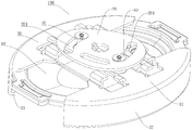
- FIG. 1 is a schematic structural view of an upper cover assembly of an electric pressure cooker according to an embodiment of the present invention
- FIG. 2 is a top plan view of an upper cover assembly of an electric pressure cooker in accordance with one embodiment of the present invention
- FIG. 3 is a side elevational view of an upper cover assembly of an electric pressure cooker in accordance with one embodiment of the present invention.
- Figure 4 is a cross-sectional view taken along line A-A of Figure 2;
- Figure 5 is a schematic enlarged view of the structure I in Figure 4.
- FIG. 6 is a schematic structural view of an elastic member of an upper cover assembly of an electric pressure cooker according to an embodiment of the present invention.
- Figure 7 is a side elevational view of an elastic member of an upper cover assembly of an electric pressure cooker in accordance with one embodiment of the present invention.
- Figure 8 is a cross-sectional view of an elastic member of an upper cover assembly of an electric pressure cooker in accordance with one embodiment of the present invention.
- FIG. 9 is a top plan view of an elastic member of an upper cover assembly of an electric pressure cooker according to an embodiment of the present invention.
- Figure 10 is a schematic view showing the structure of a cushioning member of an upper cover assembly of an electric pressure cooker according to an embodiment of the present invention.
- Figure 11 is a cross-sectional view of an upper cover assembly of an electric pressure cooker in accordance with another embodiment of the present invention.
- Figure 12 is a schematic enlarged view of the structure of Figure 11;
- FIG. 13 is a schematic structural view of an elastic member of an upper cover assembly of an electric pressure cooker according to another embodiment of the present invention.
- FIG. 14 is a schematic structural view of a stopper pad of an upper cover assembly of an electric pressure cooker according to an embodiment of the present invention.
- Fastening member 30 support portion 31; snap portion 32; inner buckle edge 33;
- Strut 40 strut body 41; annular flange 42; stop washer 43;
- Elastic member 50 sleeve 51; elastic claw 52; inner concave portion 521; outer convex portion 522; inner flange 53;
- an upper cover assembly 100 of an electric pressure cooker may include an upper cover The body 10, the rotating chuck 20, the two fastening members 30, the two legs 40 and the two elastic members 50.
- the number of the fastening member 30, the support member 40, and the elastic member 50 is not limited thereto, and may be set according to a specific situation, but the number of the fastening member 30 and the support member 40 is at least not less than two, and the number of the elastic members 50 is at least one. .
- the spin chuck 20 is pivotally coupled to the upper cover body 10, that is, the spin chuck 20 is coupled to the upper cover body 10 and is pivotable relative to the upper cover body 10.
- the rotating chuck 20 may be located above the upper cover body 10.
- the rotating chuck 20 may be coupled to the upper cover body via a rotating shaft. As shown in FIG. 1, the middle portion of the rotating chuck 20 may be provided with a shaft hole for passing the rotating shaft.
- each of the card slots is formed as an arcuate card slot 201, and the plurality of arcuate card slots 201 are distributed along the circumferential direction of the spin chuck 20, and each of the arcuate card slots 201 is eccentric with respect to the center of the spin chuck 20.
- each of the arcuate card slots 201 does not coincide with the center of the spin chuck 20, and the direction of extension of each of the arcuate card slots 201 is not along the circumferential direction of the spin chuck 20, but relative to the rotation.
- the circumferential direction of the chuck 20 extends obliquely.
- the plurality of fastening members 30, the plurality of pillars 40, the plurality of elastic members 50, and the plurality of curved card slots 201 are respectively in one-to-one correspondence.
- Each of the fastening members 30 is respectively adapted to be engaged with the outer pot of the electric pressure cooker, and the plurality of fastening members 30 are movably connected to the upper cover body 10, that is, the plurality of fastening members 30 are connected to the upper cover body 10. And movable relative to the upper cover body 10.
- a plurality of struts 40 are connected to the corresponding fastening members 30 to drive the fastening members 30 to move.
- the plurality of struts 40 cooperate with the corresponding curved slots 201 and extend along the curved slot 201 along the curved slot 201. Can be active.
- the arcuate card slot 201 rotates relative to the strut 40. Since the arcuate card slot 201 is eccentrically disposed with respect to the center of the spin chuck 20, the arcuate card slot 201 will Applying a radial force to the strut 40, thereby driving the engaging member 30 connected thereto to move in the radial direction of the rotating chuck 20, thereby engaging or disengaging the outer pot, so that the electric pressure cooker can be closed or opened. .
- a plurality of elastic members 50 are provided between the outer peripheral surface of the corresponding strut 40 and the inner peripheral surface of the arcuate card slot 201.
- the inner peripheral wall is in indirect contact, and the elastic member 50 can be elastically deformed by a force, and has a certain buffering effect, and can offset the radial force of the rotating chuck 20 on the strut 40, so that the radial force received by the strut 40 is reduced, thereby
- the deformation of the pillar 40 is reduced, and the elastic property of the elastic member 50 itself can effectively reduce the wear between the structural members, thereby improving the smoothness and stability of the rotation of the electric pressure cooker, and the electric pressure cooker opening and closing cover is smooth and the operation noise is small.
- the elastic member 50 is disposed between the outer peripheral surface of the strut 40 and the inner peripheral wall of the arcuate card slot 201, so that the force of the spin chuck 20 received by the strut 40 is reduced.
- the damage of the strut 40 and the wear between the structural members are reduced, so that the upper cover assembly 100 is smooth in operation and high in reliability.
- the card slot provided on the spin chuck 20 is not limited to being formed into an arc shape, for example, in the present invention.
- the card slot may also be a straight slot, and the straight slot does not extend through the center of the spin chuck 20, in other words, the card slot does not extend in the radial direction of the spin chuck 20, and extends obliquely with respect to the radial direction. .
- the strut 40 moves within the card slot, the strut 40 can be moved in the radial direction of the spin chuck 20, thereby causing the snap member 30 to move radially to engage or disengage the outer pot.
- the elastic member 50 may be disposed between the outer circumferential surface of one or some of the pillars 40 and the inner circumferential surface of the card slot to specifically prevent one or some of the pillars 40 and the card slot from being damaged. .
- the upper cover body 10 may be provided with a plurality of guiding portions extending along a radial direction thereof, and the plurality of fastening members 30 are slidably and correspondingly guided with respect to the upper cover body 10.
- the guiding portion can guide, position and limit the movement of the fastening component 30, so that the fastening component 30 can be accurately moved inward or outward along the axial direction of the upper cover body 10 under the driving of the pillar 40, thereby The buckle or the separation of the outer pot is realized, the switch cover is operated accurately, and the upper cover assembly 100 has high assembly accuracy.
- the guide portion may be formed as a guide rail or a guide groove or the like.
- the radial direction of the upper cover body 10 refers to a direction in which a straight line perpendicular to the axial direction of the upper cover body 10 and passes through the center of the upper cover body 10, and when the upper cover body 10 is formed in a circular shape, the upper cover body 10
- the radial direction is the direction of the diameter.
- the radial direction of the upper cover body 10 can be understood to connect the center of the upper cover body 10 and the edge of the upper cover body 10 at any point. The direction in which the straight line extends.
- the upper cover body 10 has an elliptical shape as a whole.
- the upper cover assembly 100 is also substantially elliptical.
- the electric pressure cooker having the upper cover assembly 100 is an elliptical pressure cooker.
- the radial direction of the upper cover body 10 is the axis passing through the center of the upper cover body 10 and the upper cover body 10. The direction of the vertical straight line.
- each short shaft portion of the upper cover body 10 is provided with a fastening component 30 (ie, two fastening components 30 are provided, of course, more than two buckles may be provided according to specific conditions. Assembly 30).
- the rotating chuck 20 is provided with two curved card slots 201.
- Each of the curved cards 201 is provided with a pillar 40, and each of the pillars is sleeved with an elastic member 50.
- the elastic member 50 is sleeved on the pillar 40.
- the resilient member 50 can include a sleeve 51 and a plurality of resilient jaws 42.
- the sleeve 51 is sleeved on the support 40, and at least one end of the sleeve 51 is provided with a plurality of elastic claws 42, that is, a plurality of elastic claws 42 may be provided at the upper end or the lower end of the sleeve 51, or at the same time.
- the upper and lower ends of 51 are examples of resilient jaws 42.
- the plurality of elastic claws 42 may be distributed along the circumferential direction of the sleeve 51, and each of the elastic claws 42 may extend obliquely outward and away from the sleeve 51 in the axial direction of the sleeve 51. That is, the elastic claws 42 simultaneously extend in the axial direction and the radial direction of the sleeve 51.
- the elastic claw 42 bears the radial force of the spin chuck 20 and elastically deforms, thereby effectively canceling the radial force of the spin chuck 20, reducing the strut 40 Stress, effective protection Pillar 40.
- the two ends of the sleeve 51 are provided with six elastic claws 42.
- the upper end and the lower end of the elastic member 50 are formed into a rising structure, and the upper end of the elastic member 50 is formed. Both the lower end and the lower end can be abutted against the inner peripheral wall of the curved card slot 201, and the elastic member 50 is more evenly balanced and has stable deformation, thereby ensuring smooth and smooth movement of the fastening member 30.
- each of the elastic claws 42 includes an inner concave portion 521 and an outer convex portion 522 , and one end of the inner concave portion 521 may be connected to the sleeve 51 , and the other end of the inner concave portion 521 and the outer convex portion 522 .
- One end is connected, that is, the inner recess 521 is connected between the outer convex portion 522 and the sleeve 51.
- the angle between the tangent of the inner recess 521 and the axis of the sleeve 51 gradually increases.
- the angle between the tangent of the convex portion 522 and the axis of the sleeve 51 gradually decreases.
- the inner concave portion 521 is recessed inward, and is formed as an outer curved structure that is curved away from the axis of the sleeve 51, and the outer convex portion 522 protrudes outward and is formed as an inner curved structure that is curved toward the axis of the sleeve 51.
- the deformability of the elastic member 50 is better, and the radial force of the rotating chuck 20 on the strut 40 can be better offset, and the buffering effect is better, and the impact of the rotating chuck 20 on the strut 40 can be better buffered. , more effective protection of the pillar 40, and the operation is smoother.
- each of the resilient claws 42 remote from the sleeve 51 is provided with an inwardly extending inwardly extending edge 53. That is, one end of the outer convex portion 522 away from the inner concave portion 521 is provided with an inner flange 53 which extends toward the axis of the sleeve 51.
- the inturned edge 53 can make the structure of the elastic member 50 more rounded.
- the inner flange 53 is smoothly connected to the elastic claws 42. In other words, the connection between the inner flange 53 and the elastic claw 42 is smoothly transitioned. Thereby, the structure of the elastic member 50 can be made more round, the appearance is more beautiful, and the disassembly and assembly safety is high.
- the resilient pawl 42 can be smoothly coupled to the sleeve 51. Thereby, the appearance and disassembly safety of the elastic member 50 can be further improved.
- one end of the adjacent two elastic claws 42 adjacent to the sleeve 51 is connected to each other.
- the plurality of elastic claws 42 provided at one end of the sleeve 51 can be connected and formed integrally, so that the elastic member 50 has higher structural strength, more uniform deformation, good deformability, and the opening and closing cover operation is smoother and more reliable.
- the elastic member 50 may be a stainless steel member. That is, the elastic member 50 may be made of a stainless steel material such as food grade stainless steel. Therefore, the elastic member 50 is not only easy to manufacture, but also relatively low in cost, and is less prone to rust and damage, and has a long service life, ensuring smoothness and reliability of the operation of the upper cover assembly 100.
- the elastic member 50 can be an integrally formed piece.
- the integrally formed structure not only facilitates manufacture, but also ensures the overall structural strength and stability of the elastic member 50, and simplifies the assembly operation of the upper cover assembly 100.
- the upper cover assembly 100 may further include a cushioning member 60, and the cushioning member 60 may be sleeved on the elastic member 50.
- the elastic member 50 can be restrained between the cushioning member 60 and the strut 40.
- the cushioning member 60 has a certain cushioning effect, and can further absorb the force of the rotating chuck 20, thereby further reducing the diameter of the rotating chuck 20 to the strut 40. The force acts to further protect the strut 40 while making the strut 40 move more smoothly.
- the cushioning member 60 may be a polyoxymethylene member, that is, the cushioning member 60 may be made of polyoxymethylene (POM).
- the cushioning member 60 can have a self-lubricating effect, and the wear between the cushioning member 60 and the rotating chuck 20 and the elastic member 50 can be reduced, the engaging member 30 can be moved more smoothly, and the operation noise is small.
- FIG. 10 A cushioning member 60 of the upper cover assembly 100 according to an embodiment of the present invention is shown in FIG. 10, (a) is a side view of the cushioning member 60, and (b) is a plan view of the cushioning member 60. As shown in FIG. 10, the cushioning member 60 may be formed in a cylindrical structure having a constant radial dimension. The cushioning member 60 is easy to manufacture and has a good cushioning effect.
- the structure of the fastening member 30 can be formed into a plurality of types as long as it can be engaged with the outer pot.
- the fastening component 30 may include a support portion 31 and a snap portion 32.
- the supporting portion 31 is connected to the pillar 40.
- the supporting portion 31 is supported on the upper cover body 10.
- the upper end of the engaging portion 32 is connected to the outer edge of the supporting portion 31, and the lower end of the engaging portion 32 can extend inward to form an inner buckle 33.
- the inner buckle edge 33 is engaged with the outer pot.
- the fastener 30 of this construction is easy to manufacture and has good fit with the outer pot.
- the fastening component 30 includes two, and the two fastening components 30 are spaced apart along the circumferential direction of the upper cover body 10, as shown in FIGS. 1 and 2, the radial sides of the upper cover body 10 A fastening member 30 is respectively provided, and the two fastening members 30 can be engaged or disengaged from the outer pot under the driving of the pillar 40, so that both sides of the upper cover assembly 100 can be engaged or opened with the outer pot.
- the fastening property is good, and the sealing property of the upper cover assembly 100 and the outer pot is ensured.
- the number of the arcuate card slots 201 , the strut 40 , the elastic member 50 , and the cushioning member 60 may be two, respectively, to correspond one-to-one with the fastening component 30 .
- the strut 40 includes a strut body 41, an annular flange 42, and a stop washer 43.
- the pillar body 41 can be disposed in the arcuate card slot 201.
- the upper end of the pillar body 41 protrudes upwardly from the arcuate card slot 201, and the stopper pad 43 is disposed at the upper end of the pillar body 41.
- the stopper pad 43 It is fixedly connected to the pillar body 41 by screws.
- the lower end of the pillar body 41 protrudes downwardly from the arcuate card slot 201, and the lower end of the pillar body 41 is connected to the fastening member 30.
- the pillar body 41 is riveted to the support portion 31 of the fastening member 30.
- the annular flange 42 is disposed at a lower portion of the pillar body 41.
- the elastic member 50 is sleeved on the pillar body 41.
- the lower end of the elastic member 50 abuts against the upper surface of the annular flange 42.
- the cushioning member 60 is sleeved on the elastic member 50 for buffering.
- the lower end of the member 60 abuts against the upper surface of the annular flange 42.
- the size of the stop pad 43 is larger than the width of the arcuate card slot 201.
- the stop pad 43 may be formed in a circular shape, and the middle portion of the stop pad 43 may be provided with a fixed through hole, and the screw may pass through the fixed through hole from above, with the post 40 When connected, the large end of the screw can be stopped on the upper surface of the stop pad 43, so that the stop pad 43 and the post 40 are fixedly coupled together, and the fixing is firm and the assembly operation is convenient.
- the structure of the elastic member 50 is not limited to the above description, and may be other structures, for example, as shown in the figure. 11 to FIG. 13 , the elastic member 50 may be a silicone ring, and the silicone ring may be sleeved on the pillar 40 so that the outer circumferential surface of the pillar 40 can be spaced apart from the inner circumferential surface of the card slot, and the silicone ring has elasticity to enable the pillar.
- a resilient stop is formed between the 40 and the card slot to effectively reduce the risk of damage to the strut 40 and the spin chuck 20.
- the strut 40 includes a strut body 41, an annular flange 42, and a stop pad 43, and the lower end of the silicone ring can abut against the upper surface of the annular flange 42.
- the lower end of the inner circumferential surface of the silicone ring can be formed into a notched structure, so that the opening of the lower end of the silicone ring is large, which is convenient for assembly operation.
- the cross section of the silicone ring can be formed into a circular shape to better match the support 40 to ensure a better cushioning effect.
- the upper cover assembly 100 and the fastening structure are subjected to the steam pressure in the pot.
- the strength and rigidity of the position of the pillar 40 must be considered.
- the upper cover assembly 100 according to the embodiment of the present invention has a novel fastening structure. Two elements are added at the position of the support post 40: the elastic member 50 and the buffer member 60. On the one hand, they have a certain buffering effect and can reduce the arc.
- the shaped card slot 201 exerts a radial force on the strut 40, thereby reducing the deformation of the strut 40; on the other hand, they have self-lubricating effect or elastic property, which can effectively reduce the wear between the structural members, thereby improving their rotational smoothness.
- the upper cover assembly 100 according to the embodiment of the present invention has a smooth operation and high reliability, a long service life, and low operation noise.
- the stop pad 43 can form a stop for the rotating chuck 20 and the strut 40.
- the rotating chuck 20, the strut 40 and the engaging member 30 connected to the strut 40 are not easily separated from the outer pot. It ensures the firmness of the cover and is safe and reliable to use.
- the capping principle of the upper cap assembly 100 is: first, the rotating chuck 20 is biased to pivot in one direction along its own axial direction (for example, clockwise direction). At this time, the arcuate card slot 201 It is movable, since the arcuate card slot 201 is eccentrically disposed with respect to the center of the spin chuck 20, when the arcuate card slot 201 moves, the strut 40 that projects into the arcuate card slot 201 is in the radial direction of the spin chuck 20. It does not move, but stops moving on the inner peripheral wall of the curved card slot 201, and realizes the movement in the radial direction of the rotary chuck 20. When the column 40 moves, the fastener 30 connected thereto is rotated. The chuck 20 moves in the radial direction, and the fastening member 30 moves to engage with a structure on the outer pot, for example, a tooth or the like, and the electric pressure cooker realizes closing.
- the elastic member 50 is disposed between the outer peripheral surface of the strut 40 and the inner peripheral wall of the arcuate card slot 201, the elastic member 50 is elastically deformed by force, and the radial force of the rotating chuck 20 against the strut 40 can be cancelled, thereby The radial force received by the strut 40 is reduced, the deformation of the strut 40 is reduced, and the elastic property of the elastic member 50 itself can effectively reduce the wear between the structural members, thereby improving their smoothness and stability.
- the electric pressure cooker is smoothly closed and the operation noise is small.
- the opening operation of the upper cover assembly 100 is exactly the opposite of the closing operation, even if the rotating chuck 20 is forced to pivot in the other direction along its own axial direction (for example, counterclockwise), thereby driving The strut 40 moves in the opposite direction, thereby causing the engaging member 30 to move in the opposite direction, so that the separation from the outer pot can be achieved. Due to the presence of the elastic member 50, the opening operation is performed. It is smoother and less noisy.
- An electric pressure cooker may include an outer pot, an inner pot, and an upper lid assembly 100 according to an embodiment of the present invention.
- the inner pot is disposed in the outer pot, and the outer pot can be provided with a fitting portion for engaging with the fastening component 30, so that the upper lid assembly 100 can be engaged with the outer pot, since the upper lid assembly 100 according to the embodiment of the invention has The above advantageous technical effects, therefore, the electric pressure cooker switch cover according to the embodiment of the invention is convenient, smooth and reliable, and has a long service life.
- first and second are used for descriptive purposes only and are not to be construed as indicating or implying a relative importance or implicitly indicating the number of technical features indicated.
- features defining “first” or “second” may include at least one of the features, either explicitly or implicitly.
- the meaning of "a plurality” is at least two, such as two, three, etc., unless specifically defined otherwise.
- the terms “installation”, “connected”, “connected”, “fixed” and the like shall be understood broadly, and may be either a fixed connection or a detachable connection, unless explicitly stated and defined otherwise. Or in one piece; it may be a mechanical connection, or it may be an electrical connection or a communication with each other; it may be directly connected or indirectly connected through an intermediate medium, and may be an internal connection of two elements or an interaction relationship between two elements. Unless otherwise expressly defined. For those skilled in the art, the specific meanings of the above terms in the present invention can be understood on a case-by-case basis.
- the first feature "on” or “under” the second feature may be a direct contact of the first and second features, or the first and second features may be indirectly through an intermediate medium, unless otherwise explicitly stated and defined. contact.
- the first feature "above” the second feature may be that the first feature is directly above or above the second feature, or merely that the first feature level is higher than the second feature.
- the description of the terms “embodiment”, “specific embodiment”, “example” or “specific example” and the like means that the specific features, structures, materials or features described in connection with the embodiment or the examples are included. In at least one embodiment or example of the invention. In the present specification, the schematic representation of the above terms is not necessarily directed to the same embodiment or example. Furthermore, the particular features, structures, materials, or characteristics described may be combined in a suitable manner in any one or more embodiments or examples. In addition, various embodiments or examples described in the specification, as well as features of various embodiments or examples, may be combined and combined.
Landscapes
- Engineering & Computer Science (AREA)
- Food Science & Technology (AREA)
- Cookers (AREA)
Abstract
Applications Claiming Priority (12)
| Application Number | Priority Date | Filing Date | Title |
|---|---|---|---|
| CN201610136964 | 2016-03-10 | ||
| CN201620184684 | 2016-03-10 | ||
| CN201620184684.X | 2016-03-10 | ||
| CN201610136964.8 | 2016-03-10 | ||
| CN201610363577.8 | 2016-05-26 | ||
| CN201610362818.7A CN107432667A (zh) | 2016-05-26 | 2016-05-26 | 电压力锅和电压力锅的上盖组件 |
| CN201610363577.8A CN107174116B (zh) | 2016-03-10 | 2016-05-26 | 电压力锅和电压力锅的上盖组件 |
| CN201620503854 | 2016-05-26 | ||
| CN201620503853.1 | 2016-05-26 | ||
| CN201620503854.6 | 2016-05-26 | ||
| CN201620503853.1U CN205849255U (zh) | 2016-03-10 | 2016-05-26 | 电压力锅和电压力锅的上盖组件 |
| CN201610362818.7 | 2016-05-26 |
Publications (1)
| Publication Number | Publication Date |
|---|---|
| WO2017152518A1 true WO2017152518A1 (fr) | 2017-09-14 |
Family
ID=59788866
Family Applications (1)
| Application Number | Title | Priority Date | Filing Date |
|---|---|---|---|
| PCT/CN2016/084362 Ceased WO2017152518A1 (fr) | 2016-03-10 | 2016-06-01 | Autocuiseur électrique et ensemble de couvercle supérieur d'autocuiseur électrique |
Country Status (1)
| Country | Link |
|---|---|
| WO (1) | WO2017152518A1 (fr) |
Cited By (17)
| Publication number | Priority date | Publication date | Assignee | Title |
|---|---|---|---|---|
| CN109393993A (zh) * | 2018-11-26 | 2019-03-01 | 江门市南光电器实业有限公司 | 一种锅盖锁扣结构及其多功能锅 |
| US10390656B2 (en) | 2017-08-09 | 2019-08-27 | Sharkninja Operating Llc | Cooking device and components thereof |
| USD873602S1 (en) | 2018-08-09 | 2020-01-28 | Sharkninja Operating Llc | Lid part of a food preparation device |
| USD874211S1 (en) | 2018-08-09 | 2020-02-04 | Sharkninja Operating Llc | Food preparation device and parts thereof |
| CN111728471A (zh) * | 2020-06-30 | 2020-10-02 | 宁波方太厨具有限公司 | 一种自适应热风结构及具有该结构的烹饪装置 |
| USD903415S1 (en) | 2018-08-09 | 2020-12-01 | Sharkninja Operating Llc | Cooking basket |
| USD914436S1 (en) | 2018-06-19 | 2021-03-30 | Sharkninja Operating Llc | Air diffuser with food preparation pot |
| USD918654S1 (en) | 2019-06-06 | 2021-05-11 | Sharkninja Operating Llc | Grill plate |
| USD922126S1 (en) | 2019-06-06 | 2021-06-15 | Sharkninja Operating Llc | User interface for a food preparation device |
| US11033146B2 (en) | 2019-02-25 | 2021-06-15 | Sharkninja Operating Llc | Cooking device and components thereof |
| US11134808B2 (en) | 2020-03-30 | 2021-10-05 | Sharkninja Operating Llc | Cooking device and components thereof |
| USD932833S1 (en) | 2018-08-09 | 2021-10-12 | Sharkninja Operating Llc | Reversible cooking rack |
| CN113907623A (zh) * | 2021-08-20 | 2022-01-11 | 遨博(北京)智能科技有限公司 | 一种食材加料装置及机械臂协作的自动化厨房 |
| CN114305115A (zh) * | 2021-12-31 | 2022-04-12 | 德奥通用航空股份有限公司 | 具有旋钮开关的茶罐及茶饮机 |
| CN115656414A (zh) * | 2022-09-08 | 2023-01-31 | 哈尔滨理工大学 | 一种电缆电线低烟性检测装置 |
| US11751710B2 (en) | 2019-02-25 | 2023-09-12 | Sharkninja Operating Llc | Guard for cooking system |
| CN119302546A (zh) * | 2024-12-17 | 2025-01-14 | 杭州利钛科技发展有限公司 | 锅盖和压力锅 |
Citations (5)
| Publication number | Priority date | Publication date | Assignee | Title |
|---|---|---|---|---|
| KR100188059B1 (ko) * | 1996-06-29 | 1999-06-01 | 우영일 | 전기 압력밥솥의 뚜껑 개폐장치 |
| JP2007229137A (ja) * | 2006-02-28 | 2007-09-13 | Katsufumi Aoyanagi | 圧力調理器 |
| CN201094558Y (zh) * | 2007-07-31 | 2008-08-06 | 浙江苏泊尔家电制造有限公司 | 压力锅开合盖结构 |
| CN201617653U (zh) * | 2009-12-11 | 2010-11-03 | 珠海格力电器股份有限公司 | 一种电压力锅 |
| KR101013451B1 (ko) * | 2008-11-06 | 2011-02-14 | 킴스홀딩스 주식회사 | 조리용 압력용기 뚜껑 록킹장치 |
-
2016
- 2016-06-01 WO PCT/CN2016/084362 patent/WO2017152518A1/fr not_active Ceased
Patent Citations (5)
| Publication number | Priority date | Publication date | Assignee | Title |
|---|---|---|---|---|
| KR100188059B1 (ko) * | 1996-06-29 | 1999-06-01 | 우영일 | 전기 압력밥솥의 뚜껑 개폐장치 |
| JP2007229137A (ja) * | 2006-02-28 | 2007-09-13 | Katsufumi Aoyanagi | 圧力調理器 |
| CN201094558Y (zh) * | 2007-07-31 | 2008-08-06 | 浙江苏泊尔家电制造有限公司 | 压力锅开合盖结构 |
| KR101013451B1 (ko) * | 2008-11-06 | 2011-02-14 | 킴스홀딩스 주식회사 | 조리용 압력용기 뚜껑 록킹장치 |
| CN201617653U (zh) * | 2009-12-11 | 2010-11-03 | 珠海格力电器股份有限公司 | 一种电压力锅 |
Cited By (79)
| Publication number | Priority date | Publication date | Assignee | Title |
|---|---|---|---|---|
| US10646070B2 (en) | 2017-08-09 | 2020-05-12 | Sharkninja Operating Llc | Cooking device and components thereof |
| US11363910B2 (en) | 2017-08-09 | 2022-06-21 | Sharkninja Operating Llc | Cooking device and components thereof |
| US10405697B2 (en) | 2017-08-09 | 2019-09-10 | Sharkninja Operating Llc | Cooking device and components thereof |
| US10405698B2 (en) | 2017-08-09 | 2019-09-10 | Sharkninja Operating Llc | Cooking device and components thereof |
| US10413122B2 (en) | 2017-08-09 | 2019-09-17 | Sharkninja Operating Llc | Cooking device and components thereof |
| US10413121B2 (en) | 2017-08-09 | 2019-09-17 | Sharkninja Operating Llc | Cooking device and components thereof |
| US10485378B2 (en) | 2017-08-09 | 2019-11-26 | Sharkninja Operating Llc | Cooking device and components thereof |
| US11889950B2 (en) | 2017-08-09 | 2024-02-06 | Sharkninja Operating Llc | Cooking device and components thereof |
| US11759048B2 (en) | 2017-08-09 | 2023-09-19 | Sharkninja Operating Llc | Cooking device and components thereof |
| US11759049B2 (en) | 2017-08-09 | 2023-09-19 | Sharkninja Operating Llc | Cooking device and components thereof |
| US11627834B2 (en) | 2017-08-09 | 2023-04-18 | Sharkninja Operating Llc | Cooking system for cooking food |
| US11547242B2 (en) | 2017-08-09 | 2023-01-10 | Sharkninja Operating Llc | Cooking device and components thereof |
| US11547243B2 (en) | 2017-08-09 | 2023-01-10 | Sharkninja Operating Llc | Cooking device and components thereof |
| US11445856B2 (en) | 2017-08-09 | 2022-09-20 | Sharkninja Operating Llc | Cooking device and components thereof |
| US10390656B2 (en) | 2017-08-09 | 2019-08-27 | Sharkninja Operating Llc | Cooking device and components thereof |
| US11089903B2 (en) | 2017-08-09 | 2021-08-17 | Sharkninja Operating Llc | Cooking device and components thereof |
| US11304561B2 (en) | 2017-08-09 | 2022-04-19 | Sharkninja Operating Llc | Cooking device and components thereof |
| US10674868B2 (en) | 2017-08-09 | 2020-06-09 | Sharkninja Operating Llc | Cooking device and components thereof |
| US10682011B2 (en) | 2017-08-09 | 2020-06-16 | Sharkninja Operating Llc | Cooking device and components thereof |
| US11399657B2 (en) | 2017-08-09 | 2022-08-02 | Sharkninja Operating Llc | Cooking device and components thereof |
| US10653270B2 (en) | 2017-08-09 | 2020-05-19 | Sharkninja Operating Llc | Cooking device and components thereof |
| US11089902B2 (en) | 2017-08-09 | 2021-08-17 | Sharkninja Operating Llc | Cooking device and components thereof |
| US10660472B2 (en) | 2017-08-09 | 2020-05-26 | Sharkninja Operating Llc | Cooking device and components thereof |
| US11109710B2 (en) | 2017-08-09 | 2021-09-07 | Sharkninja Operating Llc | Cooking device and components thereof |
| US11266268B2 (en) | 2017-08-09 | 2022-03-08 | Sharkninja Operating Llc | Cooking device and components thereof |
| US11278151B2 (en) | 2017-08-09 | 2022-03-22 | Sharkninja Operating Llc | Cooking device and components thereof |
| US11266267B2 (en) | 2017-08-09 | 2022-03-08 | Sharkninja Operating Llc | Cooking device and components thereof |
| USD914447S1 (en) | 2018-06-19 | 2021-03-30 | Sharkninja Operating Llc | Air diffuser |
| USD914436S1 (en) | 2018-06-19 | 2021-03-30 | Sharkninja Operating Llc | Air diffuser with food preparation pot |
| USD948938S1 (en) | 2018-06-19 | 2022-04-19 | Sharkninja Operating Llc | Air diffuser |
| USD903415S1 (en) | 2018-08-09 | 2020-12-01 | Sharkninja Operating Llc | Cooking basket |
| USD876874S1 (en) | 2018-08-09 | 2020-03-03 | Sharkninja Operating Llc | User interface for a food preparation device |
| USD873602S1 (en) | 2018-08-09 | 2020-01-28 | Sharkninja Operating Llc | Lid part of a food preparation device |
| USD929173S1 (en) | 2018-08-09 | 2021-08-31 | Sharkninja Operating Llc | Food preparation device |
| USD929793S1 (en) | 2018-08-09 | 2021-09-07 | Sharkninja Operating Llc | Food preparation device |
| USD929794S1 (en) | 2018-08-09 | 2021-09-07 | Sharkninja Operating Llc | Food preparation device |
| USD874211S1 (en) | 2018-08-09 | 2020-02-04 | Sharkninja Operating Llc | Food preparation device and parts thereof |
| USD931680S1 (en) | 2018-08-09 | 2021-09-28 | Sharkninja Operating Llc | Cooking basket |
| USD883016S1 (en) | 2018-08-09 | 2020-05-05 | Sharkninja Operating Llc | Food preparation device and parts thereof |
| USD932833S1 (en) | 2018-08-09 | 2021-10-12 | Sharkninja Operating Llc | Reversible cooking rack |
| USD883017S1 (en) | 2018-08-09 | 2020-05-05 | Sharkninja Operating Llc | User interface for food preparation device |
| USD934027S1 (en) | 2018-08-09 | 2021-10-26 | Sharkninja Operating Llc | Reversible cooking rack |
| USD883014S1 (en) | 2018-08-09 | 2020-05-05 | Sharkninja Operating Llc | Food preparation device |
| USD935259S1 (en) | 2018-08-09 | 2021-11-09 | Sharkninja Operating Llc | Food preparation device |
| USD940503S1 (en) | 2018-08-09 | 2022-01-11 | Sharkninja Operating Llc | Cooking basket |
| USD883015S1 (en) | 2018-08-09 | 2020-05-05 | Sharkninja Operating Llc | Food preparation device and parts thereof |
| USD941090S1 (en) | 2018-08-09 | 2022-01-18 | Sharkninja Operating Llc | Cooking basket |
| USD903413S1 (en) | 2018-08-09 | 2020-12-01 | Sharkninja Operating Llc | Cooking basket |
| USD920732S1 (en) | 2018-08-09 | 2021-06-01 | Sharkninja Operating Llc | Food preparation device |
| USD903414S1 (en) | 2018-08-09 | 2020-12-01 | Sharkninja Operating Llc | Cooking basket |
| CN109393993A (zh) * | 2018-11-26 | 2019-03-01 | 江门市南光电器实业有限公司 | 一种锅盖锁扣结构及其多功能锅 |
| US11751722B2 (en) | 2019-02-25 | 2023-09-12 | Sharkninja Operating Llc | Cooking device and components thereof |
| US11751710B2 (en) | 2019-02-25 | 2023-09-12 | Sharkninja Operating Llc | Guard for cooking system |
| US11363911B2 (en) | 2019-02-25 | 2022-06-21 | Sharkninja Operating Llc | Cooking device and components thereof |
| US11832761B2 (en) | 2019-02-25 | 2023-12-05 | Sharkninja Operating Llc | Cooking device and components thereof |
| US12226039B2 (en) | 2019-02-25 | 2025-02-18 | Sharkninja Operating Llc | Guard for cooking system |
| US11766152B2 (en) | 2019-02-25 | 2023-09-26 | Sharkninja Operating Llc | Cooking device and components thereof |
| US11033146B2 (en) | 2019-02-25 | 2021-06-15 | Sharkninja Operating Llc | Cooking device and components thereof |
| US11147415B2 (en) | 2019-02-25 | 2021-10-19 | Sharkninja Operating Llc | Cooking device and components thereof |
| US11051654B2 (en) | 2019-02-25 | 2021-07-06 | Sharkninja Operating Llc | Cooking device and components thereof |
| USD922126S1 (en) | 2019-06-06 | 2021-06-15 | Sharkninja Operating Llc | User interface for a food preparation device |
| USD1015798S1 (en) | 2019-06-06 | 2024-02-27 | Sharkninja Operating Llc | Food preparation device |
| USD1049746S1 (en) | 2019-06-06 | 2024-11-05 | Sharkninja Operating Llc | Food preparation device |
| USD982375S1 (en) | 2019-06-06 | 2023-04-04 | Sharkninja Operating Llc | Food preparation device |
| USD934631S1 (en) | 2019-06-06 | 2021-11-02 | Sharkninja Operating Llc | Grill plate |
| USD1054771S1 (en) | 2019-06-06 | 2024-12-24 | Sharkninja Operating Llc | Food preparation device |
| USD918654S1 (en) | 2019-06-06 | 2021-05-11 | Sharkninja Operating Llc | Grill plate |
| US11678765B2 (en) | 2020-03-30 | 2023-06-20 | Sharkninja Operating Llc | Cooking device and components thereof |
| US11647861B2 (en) | 2020-03-30 | 2023-05-16 | Sharkninja Operating Llc | Cooking device and components thereof |
| US11134808B2 (en) | 2020-03-30 | 2021-10-05 | Sharkninja Operating Llc | Cooking device and components thereof |
| US11969118B2 (en) | 2020-03-30 | 2024-04-30 | Sharkninja Operating Llc | Cooking device and components thereof |
| CN111728471B (zh) * | 2020-06-30 | 2021-08-20 | 宁波方太厨具有限公司 | 一种自适应热风结构及具有该结构的烹饪装置 |
| CN111728471A (zh) * | 2020-06-30 | 2020-10-02 | 宁波方太厨具有限公司 | 一种自适应热风结构及具有该结构的烹饪装置 |
| CN113907623A (zh) * | 2021-08-20 | 2022-01-11 | 遨博(北京)智能科技有限公司 | 一种食材加料装置及机械臂协作的自动化厨房 |
| CN114305115A (zh) * | 2021-12-31 | 2022-04-12 | 德奥通用航空股份有限公司 | 具有旋钮开关的茶罐及茶饮机 |
| CN114305115B (zh) * | 2021-12-31 | 2023-09-08 | 伊立浦集团股份有限公司 | 具有旋钮开关的茶罐及茶饮机 |
| CN115656414B (zh) * | 2022-09-08 | 2024-05-17 | 哈尔滨理工大学 | 一种电缆电线低烟性检测装置 |
| CN115656414A (zh) * | 2022-09-08 | 2023-01-31 | 哈尔滨理工大学 | 一种电缆电线低烟性检测装置 |
| CN119302546A (zh) * | 2024-12-17 | 2025-01-14 | 杭州利钛科技发展有限公司 | 锅盖和压力锅 |
Similar Documents
| Publication | Publication Date | Title |
|---|---|---|
| WO2017152518A1 (fr) | Autocuiseur électrique et ensemble de couvercle supérieur d'autocuiseur électrique | |
| CN206560311U (zh) | 电压力锅和电压力锅的上盖组件 | |
| CN104727679B (zh) | 门铰链机构及洗碗机 | |
| CN105133929B (zh) | 一种防松动执手 | |
| CN203969967U (zh) | 一种保温杯 | |
| CN107432667A (zh) | 电压力锅和电压力锅的上盖组件 | |
| CN208784402U (zh) | 烹饪器具 | |
| CN220832696U (zh) | 盖板翻转结构及净饮机 | |
| JP6033188B2 (ja) | ゲーム機用蝶番 | |
| CN209091280U (zh) | 家电设备 | |
| EP4094654B1 (fr) | Structure à charnière pour plaque de recouvrement de toilettes | |
| CN105509114B (zh) | 面盖推动结构及吸油烟机 | |
| KR101812414B1 (ko) | 옷걸이 | |
| WO2019062644A1 (fr) | Couvercle pour appareil de cuisson et appareil de cuisson le comprenant | |
| CN204002217U (zh) | 门铰链机构及洗碗机 | |
| CN211232228U (zh) | 一种显示器支架转接头结构 | |
| CN103070599A (zh) | 一种慢炖锅及锁紧组件 | |
| CN212261143U (zh) | 一种夹钳式压力锅 | |
| CN208056822U (zh) | 一种拧手锁 | |
| CN209172003U (zh) | 一种电热壶的壶盖 | |
| KR100737838B1 (ko) | 전기압력조리기의 덮개부 | |
| CN214180093U (zh) | 锅盖与锅具 | |
| CN210068729U (zh) | 一种具有角度调节锁止的旋转装置 | |
| CN209339742U (zh) | 一种防猫眼开锁门把手结构及具有其的门锁 | |
| CN117281391B (zh) | 盖板翻转结构及净饮机 |
Legal Events
| Date | Code | Title | Description |
|---|---|---|---|
| NENP | Non-entry into the national phase |
Ref country code: DE |
|
| 121 | Ep: the epo has been informed by wipo that ep was designated in this application |
Ref document number: 16893165 Country of ref document: EP Kind code of ref document: A1 |
|
| 122 | Ep: pct application non-entry in european phase |
Ref document number: 16893165 Country of ref document: EP Kind code of ref document: A1 |
|
| 32PN | Ep: public notification in the ep bulletin as address of the adressee cannot be established |
Free format text: NOTING OF LOSS OF RIGHTS PURSUANT TO RULE 112(1) EPC (EPO FORM 1205N DATED 16.11.2018) |
|
| 122 | Ep: pct application non-entry in european phase |
Ref document number: 16893165 Country of ref document: EP Kind code of ref document: A1 |