WO2017154083A1 - 分析装置 - Google Patents
分析装置 Download PDFInfo
- Publication number
- WO2017154083A1 WO2017154083A1 PCT/JP2016/057020 JP2016057020W WO2017154083A1 WO 2017154083 A1 WO2017154083 A1 WO 2017154083A1 JP 2016057020 W JP2016057020 W JP 2016057020W WO 2017154083 A1 WO2017154083 A1 WO 2017154083A1
- Authority
- WO
- WIPO (PCT)
- Prior art keywords
- valve
- sample
- sample introduction
- elution
- pump
- Prior art date
- Legal status (The legal status is an assumption and is not a legal conclusion. Google has not performed a legal analysis and makes no representation as to the accuracy of the status listed.)
- Ceased
Links
Images










Classifications
-
- G—PHYSICS
- G01—MEASURING; TESTING
- G01N—INVESTIGATING OR ANALYSING MATERIALS BY DETERMINING THEIR CHEMICAL OR PHYSICAL PROPERTIES
- G01N30/00—Investigating or analysing materials by separation into components using adsorption, absorption or similar phenomena or using ion-exchange, e.g. chromatography or field flow fractionation
- G01N30/02—Column chromatography
- G01N30/04—Preparation or injection of sample to be analysed
- G01N30/16—Injection
- G01N30/20—Injection using a sampling valve
-
- G—PHYSICS
- G01—MEASURING; TESTING
- G01N—INVESTIGATING OR ANALYSING MATERIALS BY DETERMINING THEIR CHEMICAL OR PHYSICAL PROPERTIES
- G01N30/00—Investigating or analysing materials by separation into components using adsorption, absorption or similar phenomena or using ion-exchange, e.g. chromatography or field flow fractionation
- G01N30/02—Column chromatography
- G01N30/04—Preparation or injection of sample to be analysed
- G01N30/24—Automatic injection systems
-
- G—PHYSICS
- G01—MEASURING; TESTING
- G01N—INVESTIGATING OR ANALYSING MATERIALS BY DETERMINING THEIR CHEMICAL OR PHYSICAL PROPERTIES
- G01N30/00—Investigating or analysing materials by separation into components using adsorption, absorption or similar phenomena or using ion-exchange, e.g. chromatography or field flow fractionation
- G01N30/02—Column chromatography
- G01N30/04—Preparation or injection of sample to be analysed
- G01N30/06—Preparation
- G01N30/14—Preparation by elimination of some components
-
- G—PHYSICS
- G01—MEASURING; TESTING
- G01N—INVESTIGATING OR ANALYSING MATERIALS BY DETERMINING THEIR CHEMICAL OR PHYSICAL PROPERTIES
- G01N30/00—Investigating or analysing materials by separation into components using adsorption, absorption or similar phenomena or using ion-exchange, e.g. chromatography or field flow fractionation
- G01N30/02—Column chromatography
- G01N30/26—Conditioning of the fluid carrier; Flow patterns
- G01N30/28—Control of physical parameters of the fluid carrier
-
- G—PHYSICS
- G01—MEASURING; TESTING
- G01N—INVESTIGATING OR ANALYSING MATERIALS BY DETERMINING THEIR CHEMICAL OR PHYSICAL PROPERTIES
- G01N30/00—Investigating or analysing materials by separation into components using adsorption, absorption or similar phenomena or using ion-exchange, e.g. chromatography or field flow fractionation
- G01N30/02—Column chromatography
- G01N30/26—Conditioning of the fluid carrier; Flow patterns
- G01N30/38—Flow patterns
-
- G—PHYSICS
- G01—MEASURING; TESTING
- G01N—INVESTIGATING OR ANALYSING MATERIALS BY DETERMINING THEIR CHEMICAL OR PHYSICAL PROPERTIES
- G01N30/00—Investigating or analysing materials by separation into components using adsorption, absorption or similar phenomena or using ion-exchange, e.g. chromatography or field flow fractionation
- G01N30/02—Column chromatography
- G01N30/62—Detectors specially adapted therefor
- G01N30/72—Mass spectrometers
- G01N30/7233—Mass spectrometers interfaced to liquid or supercritical fluid chromatograph
-
- G—PHYSICS
- G01—MEASURING; TESTING
- G01N—INVESTIGATING OR ANALYSING MATERIALS BY DETERMINING THEIR CHEMICAL OR PHYSICAL PROPERTIES
- G01N30/00—Investigating or analysing materials by separation into components using adsorption, absorption or similar phenomena or using ion-exchange, e.g. chromatography or field flow fractionation
- G01N30/02—Column chromatography
- G01N30/04—Preparation or injection of sample to be analysed
- G01N30/16—Injection
- G01N30/20—Injection using a sampling valve
- G01N2030/207—Injection using a sampling valve with metering cavity, e.g. sample loop
-
- G—PHYSICS
- G01—MEASURING; TESTING
- G01N—INVESTIGATING OR ANALYSING MATERIALS BY DETERMINING THEIR CHEMICAL OR PHYSICAL PROPERTIES
- G01N30/00—Investigating or analysing materials by separation into components using adsorption, absorption or similar phenomena or using ion-exchange, e.g. chromatography or field flow fractionation
- G01N30/02—Column chromatography
- G01N30/26—Conditioning of the fluid carrier; Flow patterns
- G01N30/28—Control of physical parameters of the fluid carrier
- G01N30/32—Control of physical parameters of the fluid carrier of pressure or speed
- G01N2030/326—Control of physical parameters of the fluid carrier of pressure or speed pumps
-
- G—PHYSICS
- G01—MEASURING; TESTING
- G01N—INVESTIGATING OR ANALYSING MATERIALS BY DETERMINING THEIR CHEMICAL OR PHYSICAL PROPERTIES
- G01N30/00—Investigating or analysing materials by separation into components using adsorption, absorption or similar phenomena or using ion-exchange, e.g. chromatography or field flow fractionation
- G01N30/02—Column chromatography
- G01N30/26—Conditioning of the fluid carrier; Flow patterns
- G01N30/28—Control of physical parameters of the fluid carrier
- G01N30/32—Control of physical parameters of the fluid carrier of pressure or speed
- G01N2030/328—Control of physical parameters of the fluid carrier of pressure or speed valves, e.g. check valves of pumps
-
- G—PHYSICS
- G01—MEASURING; TESTING
- G01N—INVESTIGATING OR ANALYSING MATERIALS BY DETERMINING THEIR CHEMICAL OR PHYSICAL PROPERTIES
- G01N30/00—Investigating or analysing materials by separation into components using adsorption, absorption or similar phenomena or using ion-exchange, e.g. chromatography or field flow fractionation
- G01N30/02—Column chromatography
- G01N30/26—Conditioning of the fluid carrier; Flow patterns
- G01N30/38—Flow patterns
- G01N2030/382—Flow patterns flow switching in a single column
- G01N2030/385—Flow patterns flow switching in a single column by switching valves
-
- G—PHYSICS
- G01—MEASURING; TESTING
- G01N—INVESTIGATING OR ANALYSING MATERIALS BY DETERMINING THEIR CHEMICAL OR PHYSICAL PROPERTIES
- G01N30/00—Investigating or analysing materials by separation into components using adsorption, absorption or similar phenomena or using ion-exchange, e.g. chromatography or field flow fractionation
- G01N30/02—Column chromatography
- G01N30/62—Detectors specially adapted therefor
- G01N30/72—Mass spectrometers
Definitions
- the present invention relates to an analyzer for quantifying an analysis object.
- Patent Document 1 There is a technique described in Patent Document 1 as a technique for realizing a high-throughput analysis within 30 seconds.
- Patent Document 1 is composed of two 6-way valves, and a sample loop, a zipper, a vacuum trap, and a sample introduction pump are connected to the 6-way valve on the front stage side, and a sample is introduced into the sample loop by a vacuum suction method.
- a system having a mechanism for feeding a sample to a subsequent valve by switching the flow path of the valve is described.
- the latter stage valve is connected to a column and a sample elution pump, and after introducing the sample into the column, the flow of the valve is switched to send the sample to the later stage sample analyzer. .
- Immunoassays which are conventional testing methods, require the production of antibodies using the components to be measured as antigens, increasing the cost of testing, cross-reactions with similar compounds such as metabolites, and nonspecific reactions of antibodies. In the first place, there are drawbacks such as inapplicability to components to be measured for which antibodies cannot be produced. On the other hand, the high selectivity and sensitivity of mass spectrometers, particularly triple quadrupole mass spectrometers, can compensate for the disadvantages of immunoassays, and are expected as a new test method for clinical diagnosis.
- a pretreatment unit for pretreatment of the sample is generally required. This is to improve the accuracy and to reduce the load on the mass spectrometer by separating the impurities and the measurement target component.
- a mass spectrometer As a pretreatment unit, after separation of components of a patient sample using a liquid chromatography equipped with a solid phase extraction column (Solid Phase Extraction, SPE) or an HPLC column (High Performance Liquid Chromatography), a mass spectrometer is used. The introduction method is widely adopted.
- Liquid chromatography includes an autosampler (automatic sample injection device). A sample is sucked from a sample vial placed in a sample rack using a needle suction method, injected into an injection port of an injection valve, and a column is inserted. Introduce into the containing flow path system. In the autosampler, the needle, injection valve, injection port, and flow pipe are thoroughly cleaned to reduce carryover after sample introduction.
- autosampler automated sample injection device
- the vacuum suction method described in Patent Document 1 described above is a method in which the sample is moved in a suction state in the flow path pipe and introduced into the sample loop.
- the speed of the sample moving in the channel piping is not constant depending on the physical properties (viscosity) of the sample. For this reason, it is necessary to introduce a large amount of sample into the flow path piping before and after the sample loop as compared with the amount of sample that is measured by the sample loop arranged in the valve in the previous stage and actually introduced into the detector. Thereafter, the sample is fed to the subsequent valve by switching the flow path of the upstream valve. That is, there are not a few samples before and after the sample loop after feeding. Therefore, in the configuration described in Patent Document 1, cleaning for a certain period of time is necessary after liquid feeding. For this reason, it is difficult to perform analysis with a high throughput within 30 seconds, and it is required to speed up the cleaning process.
- An object of the present invention is to provide an analyzer capable of cleaning with high throughput.
- the present invention includes a plurality of means for solving the above-mentioned problems.
- the present invention is an analyzer for quantifying an object to be analyzed, a sample introduction part for introducing a sample into the apparatus, and the sample A processing unit for processing the sample introduced into the apparatus in the introduction unit, a detection unit for analyzing the sample processed in the processing unit, a control unit for controlling the sample introduction unit, the processing unit, and the detection unit;
- the sample introduction unit has a sample introduction valve
- the processing unit has an elution valve and a washing valve
- the washing valve is disposed between the sample introduction valve and the elution valve. It is characterized by.
- an analyzer capable of cleaning with high throughput is provided. Problems, configurations, and effects other than those described above will be clarified by the following description of examples.
- FIG. 1 is a schematic diagram illustrating a flow path configuration of a mass spectrometer of Example 1.
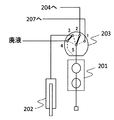
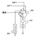
- FIG. 3 is a schematic diagram illustrating an example of the position of a syringe valve of the mass spectrometer of Example 1.
- FIG. 3 is a schematic diagram illustrating an example of the position of a syringe valve of the mass spectrometer of Example 1.
- FIG. 3 is a schematic diagram illustrating an example of the position of a syringe valve of the mass spectrometer of Example 1.
- FIG. 3 is a schematic diagram illustrating an example of the position of a syringe valve of the mass spectrometer of Example 1.
- FIG. 1 is a schematic diagram illustrating a flow path configuration of a mass spectrometer of Example 1.
- FIG. 3 is a schematic diagram illustrating an example of the position of a syringe valve of the mass spectrometer of Example 1.
- FIG. 3 is a schematic diagram illustrating an example of the position of a
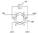
- FIG. 6 is a schematic diagram illustrating an example of a position of a sample introduction valve of the mass spectrometer of Example 1.
- FIG. 6 is a schematic diagram illustrating an example of a position of a sample introduction valve of the mass spectrometer of Example 1.
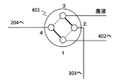
- FIG. 6 is a schematic diagram illustrating an example of a position of a cleaning valve of the mass spectrometer of Example 1.
- FIG. 6 is a schematic diagram illustrating an example of a position of a cleaning valve of the mass spectrometer of Example 1.
- FIG. FIG. 3 is a schematic diagram illustrating an example of a position of an elution valve of the mass spectrometer according to the first embodiment.
- FIG. 3 is a schematic diagram illustrating an example of a position of an elution valve of the mass spectrometer according to the first embodiment.
- 6 is a schematic diagram illustrating an example of a position of a waste liquid valve of the mass spectrometer of Example 1.
- FIG. 6 is a schematic diagram illustrating an example of a position of a waste liquid valve of the mass spectrometer of Example 1.
- FIG. 2 is a flowchart of an inspection method in the mass spectrometer of Example 1.
- FIG. FIG. 3 is a time chart of inspection in the mass spectrometer of Example 1. It is the schematic which shows the flow-path structure of the mass spectrometer of Example 2 of this invention.
- FIG. 6 is a schematic diagram illustrating an example of the position of a cleaning valve of the mass spectrometer of Example 2.
- FIG. 6 is a schematic diagram illustrating an example of the position of a cleaning valve of the mass spectrometer of Example 2.
- FIG. 6 is a schematic diagram illustrating an example of a position of an elution valve of the mass spectrometer of Example 2.
- FIG. 6 is a schematic diagram illustrating an example of a position of an elution valve of the mass spectrometer of Example 2.
- FIG. 6 is a time chart diagram of inspection in the mass spectrometer of Example 2.
- Example 1 of the mass spectrometer of the present invention will be described with reference to FIGS.
- FIG. 1 is a schematic diagram showing an overview of the mass spectrometer of the present embodiment
- FIG. 2 is a schematic diagram showing the flow path configuration of the apparatus
- FIGS. 3A to 3D are schematic diagrams showing the positions of syringe valves
- FIGS. 4A and 4B Is a schematic diagram showing the position of the sample introduction valve
- FIGS. 5A and 5B are schematic diagrams showing the position of the washing valve
- FIGS. 6A and 6B are schematic diagrams showing the position of the elution valve
- FIGS. 7A and 7B are diagrams of the waste liquid valve.
- FIG. 8 is a schematic diagram showing positions
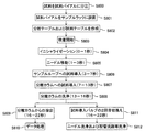
- FIG. 8 is a flowchart of an inspection method
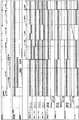
- FIG. 9 is a time chart of inspection.
- a mass spectrometer 100 is a device for quantifying the concentration of a predetermined component in a sample that is an analysis object, and includes a sample introduction unit 101, a liquid feeding unit 102, a sample concentration unit (processing unit). ) 103, the detection unit 104, and the control unit 105.
- the sample in the present invention refers to a patient sample, which is a biological sample such as serum, plasma, whole blood, urine, saliva, or cell tissue.
- the sample introduction unit 101 is an apparatus for introducing a sample into the apparatus, and includes a pump 201, a syringe 202, a syringe valve 203, a sample introduction valve 204, a needle 206, a needle cleaning port 207, and a waste liquid port. 208 and a sample loop 210, and each device is connected by a flow pipe.
- a diaphragm pump is used, which is connected to the syringe valve 203 by a flow path pipe.
- the solution is sent from the reagent bottle 209 to the pump 201.
- This solution is used for cleaning the flow path piping, the needle 206 and the syringe 202 in the sample introduction section, and is, for example, isopropanol.
- cleaning is performed by combining a plurality of solutions for the purpose of cleaning effect.
- an apparatus configuration in which the type of solution can be changed by installing an electromagnetic valve between the reagent bottle 209 and the flow path pipe of the pump 201 and switching the electromagnetic valve is also conceivable.
- the syringe valve 203 is a five-way valve having five ports, and the four flow paths can be switched by switching the position of the syringe valve 203.
- the ports 1 to 4 can be connected to the port 5, respectively, the port 2 and the port 3 can be connected, and further the port 3 and the port 4 can be connected.
- Port 1 of the syringe valve 203 is connected to the needle cleaning port 207, port 2 is connected to the sample introduction valve 204, port 3 is connected to the syringe 202, port 4 is connected to the waste liquid port 208, and port 5 is the pump 201. It is connected to the.
- the port 5 and the port 1 are connected and the port 3 and the port 2 are connected at the position shown in FIG. 3A.
- port 5 and port 2 are connected, and port 3 and port 4 are connected.
- port 5 and port 3 are connected.
- port 5 and port 4 are connected.
- the sample introduction valve 204 is a six-way valve having six ports, and includes a valve case, a rotor seal, a case spacer, and a stator. A narrow groove is cut in the rotor seal, and when an external signal is received, the rotor seal rotates appropriately, and the position can be changed by switching between position 1 and position 2.
- Port 1 of the sample introduction valve 204 is connected to the needle 206, port 2 is connected to port 2 of the syringe valve 203, port 3 and port 6 are connected to the flow path piping that becomes the sample loop 210, and port 4 is sample concentration.
- the port 5 is connected to the sample introduction pump 301 of the liquid feeding unit 102.
- FIGS. 4A and 4B The flow path switching of the sample introduction valve 204 will be described with reference to FIGS. 4A and 4B.
- FIG. 4A when the sample introduction valve 204 is positioned at position 1, port 1 and port 6, port 2 and port 3, and port 4 and port 5 are connected.
- FIG. 4B when located at position 2, port 1 and port 2, port 3 and port 4, and port 5 and port 6 are connected.
- valve in a present Example is a component which has a function which switches a flow path by installing in the arbitrary positions in the flow path of an apparatus.
- the sample loop 210 is a pipe for storing the sample sucked from the sample vial 211 on the sample rack 205 by the needle 206.
- the needle 206 moves on the sample rack 205 to the XYZ axes and sucks the sample from the sample vial 211.
- the position of the sample introduction valve 204 is switched to 1, and a flow path connecting the port 2 and the port 3 (state shown in FIG. 3A) of the syringe valve 203 is formed.
- the syringe 202, the sample loop 210, and the needle 206 are connected via the sample introduction valve 204, the sample is sucked by moving the syringe 202 by a set distance, and the sample moves from the sample vial 211 through the flow path piping.
- the sample loop 210 is filled.
- the liquid feeding unit 102 is a device for sending a solution to the sample introduction unit 101 and the sample concentration unit 103 and includes a sample introduction pump 301, a washing pump 303, and an elution pump 305.
- the cleaning pump 303 is connected to a cleaning valve 401 described later
- the sample introduction pump 301 is connected to the sample introduction valve 204
- the elution pump 305 is connected to the elution valve 402.
- Each pump is composed of a double plunger type pump with two pumping parts, and two double plunger type pumps are connected via a mixer with a connecting pipe, and the latter stage of the mixer is a single flow. It is configured to be road piping.
- the definition of a mixer in the present invention is a structure that can be efficiently mixed by passing a plurality of solutions through the mixer.
- the two reagent bottles 302A and 302C, the reagent bottles 304A and 304C, and the reagent bottles 306A and 306C are connected to each pump. Gradient analysis can be performed by controlling the flow rate and changing the solution mixing ratio.
- a double plunger type pump is used.
- a single plunger type pump, a diaphragm pump or a peristaltic pump can be used as a pumping part.
- the sample concentration unit 103 is a device for processing a sample introduced into the device, and includes a washing valve 401, an elution valve 402, and a separation column 403, each connected by a channel pipe. .
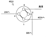
- the cleaning valve 401 is a four-way valve having four ports, and includes a valve case, a rotor seal, a case spacer, and a stator. A narrow groove is cut in the rotor seal, and when an external signal is received, the rotor seal rotates appropriately, and the position can be changed by switching between position 1 and position 2.
- Port 1 of the cleaning valve 401 is connected to port 1 of the elution valve 402, port 2 is connected to the cleaning pump 303 of the liquid feeding section 102, port 3 is connected to a waste liquid port (not shown), and port 4 is sample introduction. It is connected to port 4 of the valve 204.
- FIGS. 5A and 5B The flow path switching of the cleaning valve 401 will be described with reference to FIGS. 5A and 5B.
- FIG. 5A when the cleaning valve 401 is positioned at position 1, port 1 and port 4 are connected to port 2 and port 3.
- FIG. 5B when located at position 2, port 1 and port 2 are connected to port 3 and port 4.
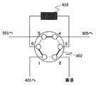
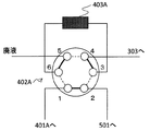
- the elution valve 402 is a six-way valve having six ports, and is composed of a valve case, a rotor seal, a case spacer, and a stator. A narrow groove is cut in the rotor seal, and when an external signal is received, the rotor seal rotates appropriately, and the position can be changed by switching between position 1 and position 2.
- Port 1 of the elution valve 402 is connected to port 1 of the washing valve 401, port 2 is connected to a waste liquid port (not shown), ports 3 and 6 are connected to the separation column 403, and port 4 is the liquid delivery unit 102.
- the port 5 is connected to the port 4 of the waste liquid valve 501 of the detection unit 104.
- FIGS. 6A and 6B The flow path switching of the elution valve 402 will be described with reference to FIGS. 6A and 6B.
- FIG. 6A when the elution valve 402 is positioned at position 1, port 1 and port 6, port 2 and port 3, and port 4 and port 5 are connected.
- FIG. 6B when located at position 2, port 1 and port 2, port 3 and port 4, and port 5 and port 6 are connected.
- the separation column 403 uses a component to be measured by utilizing the fact that a solute contained in a solution or suspension (mobile phase) flows through the column and is adsorbed or flows as it is. And a column for separating impurities.
- a C18 column in which a silica gel carrier was packed with a filler in which an octadecylsilyl group was chemically bonded was used.
- the separation mode of the separation column 403 is not limited to the reverse phase column (C18), but the reverse phase column (C8, C4), normal phase column, HILIC column, cation exchange column, anion exchange column, amide column, cyano column, molecular weight.
- a fractionation column and a PFP column can be used.
- the detection unit 104 is a device that analyzes the sample processed in the sample concentration unit 103 and includes a waste liquid valve 501 and a detector 502.
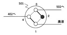
- the waste liquid valve 501 is a four-way valve that is disposed between the detector 502 and the elution valve 402 and has four ports.
- the waste liquid valve 501 also includes a valve case, a rotor seal, a case spacer, and a stator. A narrow groove is cut in the rotor seal, and when an external signal is received, the rotor seal rotates appropriately, and the position can be changed by switching between position 1 and position 2.
- Port 1 of the waste liquid valve 501 is connected to a waste liquid port (not shown), port 2 is sealed, port 3 is connected to the detector 502, and port 4 is connected to position 2 of the elution valve 402.
- FIGS. 7A and 7B The flow path switching of the waste liquid valve 501 will be described with reference to FIGS. 7A and 7B.
- FIG. 7A when the waste liquid valve 501 is located at the position 1, the port 1 and the port 4 are connected.
- FIG. 7B when the position is 2, the port 3 and the port 4 are connected.
- the detector 502 includes an ion source that ionizes a component to be measured by applying a high temperature and a high voltage, and a mass spectrometer.
- an electrospray ionization method (ESI; Electrospray Ionization) was used as the ionization method of the measurement target component in the ion source.
- Other ionization methods include atmospheric pressure chemical ionization (APCI) and the like.
- the mass spectrometer uses a triple quadrupole mass spectrometer to analyze the component to be measured in the SRM (Selected Reaction Monitoring) mode.
- SRM Select Reaction Monitoring
- other types of mass spectrometers such as a quadrupole mass spectrometer and an ion trap mass spectrometer can be used.
- the detector 502 includes a UV (Ultra Violet) detector, a diode array detector (DAD: Diode Array Detector), an NMR (Nuclear Magnetic Resonance) detector, an IR (Infrared Absorption Spectrometry) spectrometer, and a detector.
- a detector or the like can be used.
- the control unit 105 controls the operation of each part (for example, each valve, each pump, etc.) constituting the sample introduction unit 101, the liquid feeding unit 102, the sample concentration unit 103, and the detection unit 104, and at the detector 502 A computer or the like for calculating the concentration of a predetermined component in the sample from the detection result.
- the control unit 105 according to the present embodiment performs control to switch the cleaning valve 401 so as to clean the sample concentration unit 103 even when the sample introduction unit 101 introduces a sample into the apparatus.
- the sample introduction valve 204 is controlled to be switched back and forth once.
- the control unit 105 has an analysis table and a sample table, and an inspection is performed according to the input analysis table and sample table.
- An analysis table is provided for each measurement target component and is stored in the control unit 105 in advance.
- information on each parameter of the sample introduction unit 101, the liquid feeding unit 102, the sample concentration unit 103, and the detection unit 104 is set and stored for each measurement target component.
- the measurement target component, the rack position of the sample vial 211, and the number of suctions can be input, and the analysis table associated with each measurement target component is read and the inspection is performed.
- the control unit 105 can also inspect a plurality of measurement target components at the same time for one sample.
- an analysis table for inspecting a plurality of measurement target components in advance is stored in the control unit 105. It is stored, and the inspection is performed by reading the analysis table.
- the sample that needs to be urgently tested can be interrupted after the start of the test, as with a general clinical testing device, and a retest is performed based on a preset threshold of the test result. It also has a function. In those cases, the control unit 105 can adjust and perform the inspection order so that the inspection time becomes the shortest.
- testosterone molecular weight 288.1 Da
- testosterone-d3 molecular weight 291.1 Da
- the mass spectrometer 100 of a present Example can be made into the item of a general clinical test like the low molecular weight compound which exists in a sample as a measuring object component other than a testosterone.
- the measurement target components include peptides, proteins, DNA (Deoxyribo Nucleic Acid), RNA (Ribo Nucleic Acid), and the like.
- a sample is dispensed into the sample vial 211 (step S800), and placed in the sample rack 205 (step S801).
- an internal standard is added.
- the sample dispensing into the sample vial 211, the installation of the sample vial 211 into the sample rack 205, and the addition of the internal standard substance are illustrated as an example. Automatic processing can be performed by connecting devices.
- control unit 105 creates a sample table for inputting the measurement target component, the location of the sample vial 211, the suction amount and the number of suctions (step S802), and then starts measurement (step S803).
- step S804 Simultaneously with the start of the inspection, the control unit 105 performs initialization. In the initialization, signals from the control unit 105 are transmitted and received, and each component, needle, each valve position, and pump status in the apparatus are confirmed. Initialization is set to 1 second (total time 1 second).
- a signal is transmitted / received from the control unit 105 and returned to the initial position.
- the position of the sample introduction valve 204, the elution valve 402, and the waste liquid valve 501 at the time of initialization is 1.
- Position 2 when the cleaning valve 401 is initialized is 1.
- the sample introduction pump 301, the cleaning pump 303, and the elution pump 305 are initialized to a solution mixing ratio based on the analysis table.
- the solutions used in the sample introduction pump 301, the cleaning pump 303, and the elution pump 305 0.1% formic acid, 1 mmol / L ammonium formate aqueous solution
- reagent bottles 302C, 304C, 306C are added to the reagent bottles 302A, 304A, 306A.
- Acetonitrile solution containing 0.1% formic acid and 1 mmol / L ammonium formate is used. As shown in FIG.
- a solution: C solution 0%: 100%.
- Step S805 Next, the sample is introduced into the sample loop 210.
- the needle 206 moves to the position of the sample vial 211 set on the sample table. As shown in FIG. 9, the movement of the needle 206 is set to 2 seconds (total time 3 seconds).
- the control unit 105 transmits a start signal to a pump unit including the pump 201, the sample introduction pump 301, the washing pump 303, and the elution pump 305, as shown in FIG.
- the sample introduction pump 301, the cleaning pump 303, and the elution pump 305 receive this start signal, they start a gradient program.
- sample introduction into the sample loop 210 (3-7 seconds): Step S806)
- the sample is introduced into the sample loop 210 by moving the syringe 202.
- the sample passes through the sample vial 211 -needle 206 -channel piping, and the sample is introduced into the sample loop 210.
- Sample introduction is set to 4 seconds (total time 7 seconds).
- the control unit 105 starts the valve unit including the sample introduction valve 204, the washing valve 401, the elution valve 402, and the waste liquid valve 501, and the detector 502. Send a signal.
- Step S807 Sample introduction into the separation column 403 (7-13 seconds): Step S807
- the sample introduction valve 204 is switched from position 1 to position 2
- the washing valve 401 is switched from position 2 to position 1
- the sample introduction pump 301-sample loop 210-washing valve 401 are connected via the sample introduction valve 204.
- the sample inside is sent to the cleaning valve 401.
- the introduction of the sample into the separation column 403 is set to 6 seconds (total time 13 seconds).
- Step S808 Next, as shown in FIG. 9, the cleaning valve 401 is switched from position 1 to position 2 and connected to the cleaning pump 303-elution valve 402 via the cleaning valve 401, and the solution A is sent to the elution valve 402. . At that time, since the position of the elution valve 402 remains 1, the solution A is sent in the same direction as the sample introduction direction to the separation column 403, and other components to be measured (testosterone) adsorbed on the separation column 403 are obtained. Washing of impurities such as phospholipids and salts is performed. The cleaning of the separation column 403 is set to 3 seconds (total time 16 seconds).
- Step S811 The second switching of the sample introduction valve (16-22 seconds): Step S811
- the elution valve 402 and the waste liquid valve 501 are switched to position 2 and the sample introduction valve 204 is switched to position 1 ( Total time 16 seconds).
- the sample introduction valve 204 is switched to position 2.
- the reason why the sample introduction valve 204 is switched twice during the one measurement, that is, the sample introduction valve 204 is switched once during the elution of the sample to the detection unit is to reduce carryover.
- the slit is a very small gap.
- the sample introduction valve 204 when switching to the position 2 of the sample introduction valve 204 for the second time (total time of 19 seconds), the sample is eluted from the slit of the sample introduction valve 204 and sent to the cleaning valve 401.
- the sample introduction valve 204 since the position of the washing valve 401 is 2, the sample introduction valve 204—the washing valve 401—the waste liquid are connected, and the sample eluted from the slit or the like It is sent to waste liquid. That is, at the time of switching the sample introduction valve 204 in the second round-trip, the subsequent washing valve 401 exists in the position 2 state, so that the sample eluted from the slit or the like of the sample introduction valve 204 is not sent to the separation column 403. Can be discarded.
- step S810 Detection by detector 502, data processing (22-36 seconds): Step S810)
- step S809 the sample is eluted from the separation column 403, and the sample is introduced into the detector 502. Therefore, the detector 502 performs quantitative processing.
- the quantitative method will be described.
- the component to be measured having a known concentration is analyzed by the detector 502 in advance.
- These components to be measured include an internal standard substance having a known constant concentration.
- the detector 502 obtains a signal of m / z (mass / charge) derived from the measurement target component, and obtains a time change (mass chromatogram) of the signal intensity in the control unit 105 for the obtained signal.
- the control unit 105 obtains the peak area of the mass chromatogram.
- an m / z (mass / charge) signal derived from the internal standard substance is acquired by the detector 502, the time change (mass chromatogram) of the signal intensity is acquired by the control unit 105, and the peak area of the mass chromatogram is calculated.
- control unit 105 plots the concentration of the measurement target component on the X axis and the peak area ratio of the measurement target component and the peak area ratio of the internal standard substance on the Y axis, thereby creating a calibration curve.
- a calibration curve is created when the sensitivity or mass axis of the detector 502 changes during calibration performed when the apparatus is started up. Fluctuating means that the calibration result is larger than the threshold value stored in the control unit 105 in advance.
- a sample whose concentration is unknown is analyzed by the detector 502, and the control unit 105 obtains the peak area ratio of the mass chromatogram. Then, based on the prepared calibration curve, the substance concentration corresponding to the peak area of the mass chromatogram is determined.
- a stable isotope-labeled substance is adopted as the internal standard substance for each component to be measured.
- the MS transition of testosterone which is a measurement target component
- m / z 289.1 / 97.1
- the MS transition of testosterone d-3 which is an internal standard substance
- step S812 After the end of elution in the previous step S811 (total time 22 seconds), the sample introduction valve 204 and the waste liquid valve 501 are switched to position 1 as shown in FIG. On the other hand, the washing valve 401 and the elution valve 402 maintain the position 2 position. In this state, the flow path piping, the separation column 403, and each valve are cleaned using each pump. Cleaning is set to 13 seconds (total time 36 seconds).
- the pump 201-syringe valve 203-sample introduction valve 204-sample loop 210-needle 206 are connected, ports 2 and 5 of the syringe valve 203 are connected, and the solution is sent from the pump 201. Liquid is washed.
- the flow path piping between the sample introduction valve 204 and the washing valve 401 is washed by liquid feeding from the sample introduction pump 301.
- the flow path piping between the cleaning valve 401 and the elution valve 402 is cleaned by liquid feeding from the cleaning pump 303.
- the flow path piping between the elution valve 402 and the waste liquid valve 501 and the separation column 403 are washed by liquid feeding from the elution pump 305.
- the waste liquid valve 501 since the waste liquid valve 501 is in the position 1 during washing, the solution to the detection unit 104 flows into the waste liquid through the waste liquid valve 501, and the solution after washing the separation column 403 and the like passes to the detector 502. Not introduced. For this reason, the contamination of the detector 502 is reduced. That is, the frequency of maintenance of the detector 502 is reduced, and a highly accurate inspection can be realized.
- the position of the cleaning valve 401 at the time of initialization is 2, and the positions of the elution valve 402 and the waste liquid valve 501 are 1.
- the solution from the cleaning pump 303 flows through the cleaning valve 401, the elution valve 402, the separation column 403, and the waste fluid passage pipe.
- the solution from the elution pump 305 flows through the flow path of the elution valve 402-waste liquid valve 501-waste liquid.
- the solution mixing ratio of the washing pump 303 and the elution pump 305 and the positions of the washing valve 401, the elution valve 402, and the waste liquid valve 501 are maintained from the time of initialization until reception of the start signal to the valve unit (total time: 7 seconds).
- the type of solution and the solution mixing ratio in the case where testosterone is used as the measurement target component are shown, but can be appropriately changed depending on the measurement target component.
- the measurement target component is another component, since the washing valve 401 is disposed between the sample introduction valve 204 and the elution valve 402, the needle movement (1-3 seconds) and the sample introduction into the sample loop (3- 7 seconds), the measurement target component adsorbed on the separation column 403 and the flow path pipe can be cleaned, so that the inspection time can be shortened and the inspection accuracy can be improved.
- the cleaning of the needle 206 is performed immediately after the sample is introduced into the sample loop 210 by moving the syringe 202 to the lowest position. First, as shown in FIG. 9, the needle 206 moves to the needle cleaning port 207, and the outside of the needle 206 is cleaned by the solution sent from the pump 201. The outside of the needle 206 is cleaned for 9 seconds (total time 7-16 seconds).
- the position of the syringe valve 203 is switched, the port 5 and the port 3 of the syringe valve 203 are connected, the syringe 202 moves to the uppermost position (initialization position), and an unnecessary sample remaining in the needle 206 Is discharged.
- the sample is discharged for 6 seconds (total time 16-22 seconds).
- step S812 pump 201-syringe valve 203-sample introduction valve 204-sample loop 210-needle 206 are connected, ports 2 and 5 of syringe valve 203 are connected, and solution is sent from pump 201. Cleaning is performed. As a result, the inside of the needle 206 is cleaned. The inside of the needle 206 is cleaned for 13 seconds (total time 22-36 seconds).
- the sample introduction unit 101 that introduces a sample into the device, the sample concentration unit 103 that processes the sample introduced into the device, A detection unit 104 that analyzes a sample processed in the processing unit, a sample introduction unit 101, a sample concentration unit 103, and a control unit 105 that controls the detection unit 104 are provided.
- the sample introduction unit 101 includes a sample introduction valve 204.
- the sample concentration unit 103 includes an elution valve 402 and a cleaning valve 401, and the cleaning valve 401 is disposed between the sample introduction valve 204 and the elution valve 402.
- the cleaning valve 401 is disposed between the sample introduction valve 204 and the elution valve 402, the timing of the cleaning operation of the pipe flow path can be changed by appropriately switching the cleaning valve 401. Cleaning operations can be performed in parallel with other timing. As a result, a sufficient cleaning operation time can be ensured, and high-throughput cleaning is possible. Therefore, analysis with high accuracy and high throughput becomes possible.
- control unit 105 performs control to switch the cleaning valve 401 so as to clean the sample concentration unit 103 even when the sample introduction unit 101 is introducing the sample into the apparatus, so that the sample is being introduced into the sample loop 210.
- the separation column 403 and the piping channel can be washed, and high-precision analysis can be performed while the washing operation is sufficiently performed.
- the control unit 105 performs control to switch the sample introduction valve 204 one reciprocation, so that the slit and slide between the ports are extremely low capacity. Even when a 6-way valve with a dead volume on the surface is used as the sample introduction valve 204, the sample remaining in the dead volume is washed without being carried over at the next measurement, so that more accurate analysis can be performed. It can be carried out.
- the cleaning liquid can be easily supplied to the cleaning valve 401, and the high-throughput cleaning operation is performed more smoothly. Will be able to.
- the liquid feeding unit 102 further includes a sample introduction pump 301 connected to the sample introduction valve 204 and an elution pump 305 connected to the elution valve 402, so that the pipe length of the flow path pipe that performs cleaning with one pump. (Volume) can be minimized, and the cleaning operation can be efficiently performed in a short time. Therefore, cleaning with higher throughput becomes possible.
- a sample introduction pump 301 connected to the sample introduction valve 204
- an elution pump 305 connected to the elution valve 402
- Example 2 A second embodiment of the analyzer according to the present invention will be described with reference to FIGS.
- the same components as those in the first embodiment are denoted by the same reference numerals, and description thereof is omitted.
- FIG. 10 is a schematic diagram showing the flow path configuration of the mass spectrometer of the present embodiment
- FIGS. 11A and 11B are schematic diagrams showing the positions of the washing valves
- FIGS. 12A and 12B are schematic diagrams showing the positions of the elution valves.
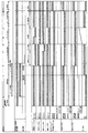
- 13 is an inspection time chart.
- the channel piping of the sample concentrating unit 103A is different from that of the sample concentrating unit 103 of Example 1.
- the apparatus configuration of the sample concentrating unit 103A will be described with reference to FIG.
- the sample concentrating unit 103A includes a washing valve 401A, an elution valve 402A, and a separation column 403A, and each is connected by a flow path pipe.
- the cleaning valve 401A is also a four-way valve having four ports like the cleaning valve 401 of the first embodiment, and includes a valve case, a rotor seal, a case spacer, and a stator. A narrow groove is cut in the rotor seal, and when an external signal is received, the rotor seal rotates appropriately, and the position can be changed by switching between position 1 and position 2.
- Port 1 of the washing valve 401A is connected to port 1 of the elution valve 402A
- port 2 is connected to the elution pump 305 of the liquid delivery unit 102
- port 3 is connected to a waste liquid port (not shown)
- port 4 is a sample introduction. It is connected to port 4 of the valve 204.
- FIGS. 11A and 11B The flow path switching of the cleaning valve 401A will be described with reference to FIGS. 11A and 11B.
- FIG. 11A when the cleaning valve 401 is positioned at position 1, port 1 and port 4 are connected to port 2 and port 3.
- FIG. 11B when located at position 2, port 1 and port 2 are connected to port 3 and port 4.
- the elution valve 402A is a six-way valve having six ports like the elution valve 402 of the first embodiment, and is composed of a valve case, a rotor seal, a case spacer, and a stator. A narrow groove is cut in the rotor seal, and when an external signal is received, the rotor seal rotates appropriately, and the position can be changed by switching between position 1 and position 2.
- Port 1 of the elution valve 402A is connected to port 1 of the cleaning valve 401A
- port 2 is connected to port 4 of the waste liquid valve 501 of the detection unit 104
- port 3 and port 6 are connected to the separation column 403A
- port 4 is
- the port 5 is connected to a waste liquid port (not shown).
- FIGS. 12A and 12B The flow path switching of the elution valve 402A will be described with reference to FIGS. 12A and 12B.
- FIG. 12A when the elution valve 402 is positioned at position 1, port 1 and port 6, port 2 and port 3, and port 4 and port 5 are connected.
- FIG. 12B when located at position 2, port 1 and port 2 are connected, port 3 and port 4 are connected, and port 5 and port 6 are connected.
- the separation column 403A is a column for separating the component to be measured and impurities in the same manner as the separation column 1 of Example 1, and a normal phase column was used in this example.
- the elution valve 402A is switched from position 1 to position 2, and the solution A is sent from the washing pump 303 to the separation column 403A via the elution valve 402A. .
- the solution A flows in the direction opposite to the sample introduction direction to the separation column 403A, and other components such as phospholipids and salts other than the measurement target component (testosterone in this embodiment) adsorbed on the separation column 403A Cleaning is performed.
- the cleaning of the separation column 403A is set to 3 seconds (total time 16 seconds).
- the position of the cleaning valve 401A at the time of initialization is 2, and the positions of the elution valve 402A and the waste liquid valve 501 are 1. That is, the solution from the elution pump 305 flows through the washing valve 401A, the elution valve 402A, the separation column 403A, the waste liquid valve 501, and the waste liquid passage pipe.
- the solution from the washing pump 303 flows through the elution valve 402A-waste liquid flow path.
- the solution mixing ratio of the washing pump 303 and the elution pump 305 and the positions of the washing valve 401A, the elution valve 402A, and the waste liquid valve 501 are maintained from the time of initialization until the start signal to the valve unit is received (total time: 7 seconds). .
- testosterone having a high hydrophobicity is used as a measurement target component, and when the organic solvent ratio of the solution is high, testosterone in the previous sample remaining adsorbed on the separation column 403A and the flow pipe is eluted, Washed.
- the needle is adsorbed on the flow path pipe between the separation column 403A and the washing valve 401A-elution valve 402A during the needle movement (1-3 seconds) and the sample introduction into the sample loop (3-7 seconds). Testosterone will be washed.
- the type of solution and the solution mixing ratio in the case where testosterone is used as the measurement target component are shown, but can be appropriately changed depending on the measurement target component. Even when the measurement target component is another component, the measurement target component adsorbed on the separation column 403A and the flow pipe during the needle movement (1-3 seconds) and the sample introduction into the sample loop (3-7 seconds) Therefore, the inspection time can be shortened and the inspection accuracy can be improved.
- each of the above-described configurations, functions, processing units, processing means, and the like can be realized by hardware by designing a part or all of them with, for example, an integrated circuit.
- Each of the above-described configurations, functions, and the like can be realized by software by the processor interpreting and executing a program that realizes each function.
- Information such as programs, tables, and files for realizing each function can be stored in a memory, a hard disk, a storage device such as an SSD (Solid State Drive), or a storage medium such as an IC card, an SD card, or a DVD.
- control lines and information lines indicate what is considered necessary for the explanation, and not all the control lines and information lines on the product are necessarily shown. Actually, it may be considered that almost all the components are connected to each other.
Landscapes
- Physics & Mathematics (AREA)
- Health & Medical Sciences (AREA)
- Life Sciences & Earth Sciences (AREA)
- Chemical & Material Sciences (AREA)
- Analytical Chemistry (AREA)
- Biochemistry (AREA)
- General Health & Medical Sciences (AREA)
- General Physics & Mathematics (AREA)
- Immunology (AREA)
- Pathology (AREA)
- Other Investigation Or Analysis Of Materials By Electrical Means (AREA)
- Sampling And Sample Adjustment (AREA)
Abstract
Description
本発明は、上記課題を解決する手段を複数含んでいるが、その一例を挙げるならば、分析対象物を定量する分析装置であって、装置内に試料を導入する試料導入部と、前記試料導入部において装置内に導入された試料を処理する処理部と、前記処理部において処理された試料を分析する検出部と、前記試料導入部、前記処理部、前記検出部を制御する制御部と、を備え、前記試料導入部は、試料導入バルブを有し、前記処理部は、溶出バルブおよび洗浄バルブを有し、前記洗浄バルブは、前記試料導入バルブと前記溶出バルブとの間に配置されていることを特徴とする。
本発明の質量分析装置の実施例1を、図1乃至図9を用いて説明する。
図1を用いて装置構成について説明する。図1に示すように、質量分析装置100は、分析対象物である試料中の所定成分の濃度を定量するための装置であり、試料導入部101、送液部102、試料濃縮部(処理部)103、検出部104および制御部105から構成される。
次に、試料導入部101について図2を用いて説明する。図2に示すように、試料導入部101は装置内に試料を導入するための装置であり、ポンプ201、シリンジ202、シリンジバルブ203、試料導入バルブ204、ニードル206、ニードル洗浄ポート207、廃液ポート208およびサンプルループ210から構成されており、それぞれの機器が流路配管で接続されている。
次に、送液部102について説明する。図2に示すように、送液部102は試料導入部101や試料濃縮部103に溶液を送るための装置であり、試料導入ポンプ301、洗浄ポンプ303および溶出ポンプ305から構成される。洗浄ポンプ303は後述する洗浄バルブ401に接続され、試料導入ポンプ301は試料導入バルブ204に接続され、溶出ポンプ305は溶出バルブ402に接続されている。
次に、試料濃縮部103について説明する。図2に示すように、試料濃縮部103は装置内に導入された試料を処理する装置であり、洗浄バルブ401、溶出バルブ402および分離カラム403から構成され、それぞれ流路配管で接続されている。
次に、検出部104について説明する。図2に示すように、検出部104は試料濃縮部103において処理された試料を分析する装置であり、廃液バルブ501および検出器502から構成される。
次に、制御部105について説明する。制御部105は、試料導入部101、送液部102、試料濃縮部103および検出部104を構成するそれぞれの部位(例えば各バルブ、各ポンプ等)の動作を制御するとともに、検出器502での検出結果から試料中の所定成分の濃度を演算するためのコンピュータ等から構成される。本実施例の制御部105は、特に、試料導入部101において試料を装置内に導入している際にも、試料濃縮部103を洗浄するよう洗浄バルブ401を切り換える制御を行う。また、試料濃縮部103から検出部104へ試料を溶出している際に、試料導入バルブ204を1往復切り換える制御を行う。
次に、本発明の典型的な一つの測定例として、テストステロンを測定対象成分とした場合の検査方法について図8および図9を用いて説明する。本実施例では、測定対象成分にテストステロン(分子量288.1Da)を、内部標準物質にテストステロン-d3(分子量291.1Da)を用いた。
次に制御部105において、測定対象成分、試料バイアル211の場所、吸引量および吸引回数を入力する試料テーブルを作成し(ステップS802)、その後に測定を開始する(ステップS803)。
検査開始と同時に、制御部105はイニシャライゼーションを行う。イニシャライゼーションでは、制御部105からの信号を送受信し、装置内の各構成要素、ニードル、各バルブのポジション、ポンプのステータスを確認する。イニシャライゼーションは1秒間(合計時間1秒)に設定されている。
次に、サンプルループ210への試料の導入が行われる。ニードル206が試料テーブルで設定された試料バイアル211の位置まで移動する。図9に示すように、ニードル206の移動は2秒間(合計時間3秒)に設定されている。ニードル206が設定された移動位置まで移動すると、図9に示すように、制御部105は、ポンプ201、試料導入ポンプ301、洗浄ポンプ303および溶出ポンプ305からなるポンプユニットにスタート信号を送信する。試料導入ポンプ301、洗浄ポンプ303および溶出ポンプ305は、このスタート信号を受信すると、グラジエントプログラムを開始する。
次に、シリンジ202が移動することでサンプルループ210へ試料の導入が行われる。試料は試料バイアル211-ニードル206-流路配管を通過し、サンプルループ210に試料が導入される。試料の導入は4秒間(合計時間7秒)に設定されている。シリンジ202が設定された移動位置まで移動すると、図9に示すように、制御部105は、試料導入バルブ204、洗浄バルブ401、溶出バルブ402、廃液バルブ501からなるバルブユニットおよび検出器502にスタート信号を送信する。
先のステップS806におけるスタート信号を受信すると、図9に示すように、試料導入バルブ204、洗浄バルブ401はポジションが切り換わる。試料導入バルブ204がポジション1からポジション2に、洗浄バルブ401がポジション2からポジション1に切り換わり、試料導入バルブ204を介して試料導入ポンプ301-サンプルループ210-洗浄バルブ401がつながり、サンプルループ210内の試料が洗浄バルブ401に送液される。その際、洗浄バルブ401および溶出バルブ402はポジション1であるため、試料は分離カラム403に吸着される。試料の分離カラム403への導入は6秒間(合計時間13秒)に設定されている。
次に、図9に示すように、洗浄バルブ401がポジション1からポジション2に切り換わり、洗浄バルブ401を介して洗浄ポンプ303-溶出バルブ402につながり、A溶液が溶出バルブ402に送液される。その際、溶出バルブ402のポジションは1のままであるため、分離カラム403への試料導入方向と同方向にA溶液が送液され、分離カラム403に吸着した測定対象成分(テストステロン)のほかのリン脂質、塩等などの夾雑物の洗浄が行われる。分離カラム403の洗浄は3秒間(合計時間16秒間)に設定されている。
次に、図9に示すように、溶出バルブ402および廃液バルブ501がポジション1からポジション2に切り換わり、溶出バルブ402および廃液バルブ501を介して、溶出ポンプ305-分離カラム403-検出器502がつながる。溶出ポンプ305からのグラジエントプログラムは、上述のように、溶出バルブ402のポジションが2に切り換わった時(合計時間16秒)に溶液混合比の変動が始まり、A溶液:C溶液=100:0(合計時間16秒)からA溶液:C溶液=0:100(合計時間21.9-22.0秒)のグラジエントプログラムが実施される。溶出ポンプ305からの溶液は、分離カラム403への試料導入方向とは逆方向に分離カラム403に送液される。試料の溶出は6秒間(合計時間22秒)に設定されている。
ステップS809における分離カラム403からの溶出工程と同じタイミングで、図9に示すように、溶出バルブ402および廃液バルブ501がポジション2に切り換わるのと同時に、試料導入バルブ204がポジション1に切り換わる(合計時間16秒)。そして3秒後(合計時間19秒)に試料導入バルブ204がポジション2に切り換わる。
先のステップS809において分離カラム403から試料が溶出され、検出器502に試料が導入されたため、検出器502において定量処理を行う。以下、定量方法について説明する。
先のステップS811における溶出の終了(合計時間22秒)の後、図9に示すように、試料導入バルブ204および廃液バルブ501がポジション1に切り換わる。一方、洗浄バルブ401および溶出バルブ402はポジション2の状態を保つ。この状態で、各ポンプを用いて流路配管、分離カラム403、各バルブの洗浄が行われる。洗浄は13秒間(合計時間36秒)に設定されている。
次に、ニードル206の洗浄について説明する。
本発明の分析装置の実施例2を図10乃至図13を用いて説明する。実施例1と同じ構成には同一の符号を示し、説明は省略する。
分離カラム403Aへの試料導入後、図13に示すように、溶出バルブ402Aがポジション1からポジション2に切り換わり、溶出バルブ402Aを介して洗浄ポンプ303からA溶液が分離カラム403Aに送液される。その際、分離カラム403Aへの試料導入方向とは逆方向にA溶液が流れ、分離カラム403Aに吸着した測定対象成分(本実施例ではテストステロン)のほかのリン脂質、塩等などの夾雑物の洗浄が行われる。分離カラム403Aの洗浄は3秒間(合計時間16秒間)に設定されている。
次に、図13に示すように、洗浄バルブ401Aおよび廃液バルブ501がポジション1からポジション2に切り換わり、同時に溶出バルブ402Aがポジション1に切り換わる。この切り換えにより、洗浄バルブ401A、溶出バルブ402Aおよび廃液バルブ501を介して、溶出ポンプ305-分離カラム403A-検出器502がつながる。溶出ポンプ305からのグラジエントプログラムは溶出バルブ402Aのポジションが2に切り換わった時(合計時間16秒)に溶液混合比の変動が始まり、A溶液:C溶液=100:0(合計時間16秒)からA溶液:C溶液=0:100(合計時間21.9-22.0秒)のグラジエントプログラムが実施される。溶出ポンプ305からの溶液は、分離カラム403Aへの試料導入方向と同方向に分離カラム403Aに送液される。試料の溶出は6秒間(合計時間22秒)に設定されている。
なお、本発明は上記した実施例に限定されるものではなく、様々な変形例が含まれる。例えば、上記した実施例は本発明を分かりやすく説明するために詳細に説明したものであり、必ずしも説明した全ての構成を備えるものに限定されるものではない。また、ある実施例の構成の一部を他の実施例の構成に置き換えることが可能であり、また、ある実施例の構成に他の実施例の構成を加えることも可能である。また、各実施例の構成の一部について、他の構成の追加・削除・置換をすることが可能である。
101…試料導入部
102…送液部
103,103A…試料濃縮部(処理部)
104…検出部
105…制御部
201…ポンプ
202…シリンジ
203…シリンジバルブ
204…試料導入バルブ
205…サンプルラック
206…ニードル
207…ニードル洗浄ポート
208…廃液ポート
209…試薬瓶
210…サンプルループ
211…試料バイアル
301…試料導入ポンプ
302A,302C,304A,304C,306A,306C…試薬瓶
303…洗浄ポンプ
305…溶出ポンプ
401,401A…洗浄バルブ
402,402A…溶出バルブ
403,403A…分離カラム
501…廃液バルブ
502…検出器
Claims (8)
- 分析対象物を定量する分析装置であって、
装置内に試料を導入する試料導入部と、
前記試料導入部において装置内に導入された試料を処理する処理部と、
前記処理部において処理された試料を分析する検出部と、
前記試料導入部、前記処理部、前記検出部を制御する制御部と、を備え、
前記試料導入部は、試料導入バルブを有し、
前記処理部は、溶出バルブおよび洗浄バルブを有し、
前記洗浄バルブは、前記試料導入バルブと前記溶出バルブとの間に配置されている
ことを特徴とする分析装置。 - 請求項1に記載の分析装置において、
前記制御部は、前記試料導入部により前記試料を装置内に導入している際にも、前記処理部を洗浄するよう前記洗浄バルブを切り換える制御を行う
ことを特徴とする分析装置。 - 請求項1に記載の分析装置において、
前記制御部は、前記処理部から前記検出部へ試料を溶出する際に、前記試料導入バルブを1往復切り換える制御を行う
ことを特徴とする分析装置。 - 請求項1に記載の分析装置において、
前記洗浄バルブに接続された洗浄ポンプを有する送液部を更に備えた
ことを特徴とする分析装置。 - 請求項4に記載の分析装置において、
前記送液部は、前記試料導入バルブに接続された試料導入ポンプ、前記溶出バルブに接続された溶出ポンプを更に有する
ことを特徴とする分析装置。 - 請求項1に記載の分析装置において、
前記検出部と前記溶出バルブとの間に、廃液バルブを更に備えた
ことを特徴とする分析装置。 - 請求項1に記載の分析装置において、
前記洗浄バルブに接続された洗浄ポンプ、前記試料導入バルブに接続された試料導入ポンプ、前記溶出バルブに接続された溶出ポンプを有する送液部を更に備え、
前記試料導入部は、シリンジバルブ、ニードル、サンプルループを更に有し、
前記処理部は、分離カラムを更に有し、
前記検出部は、廃液バルブおよび検出器を更に有し、
前記試料導入バルブは、前記試料導入ポンプ、前記洗浄バルブ、前記サンプルループ、前記シリンジバルブおよび前記ニードルに接続され、
前記洗浄バルブは、前記溶出バルブ、前記洗浄ポンプ、前記試料導入バルブおよび廃液流路に接続され、
前記溶出バルブは、前記洗浄バルブ、前記廃液バルブ、前記分離カラム、前記溶出ポンプおよび廃液流路に接続された
ことを特徴とする分析装置。 - 請求項1に記載の分析装置において、
前記洗浄バルブに接続された洗浄ポンプ、前記試料導入バルブに接続された試料導入ポンプ、前記溶出バルブに接続された溶出ポンプを有する送液部を更に備え、
前記試料導入部は、シリンジバルブ、ニードル、サンプルループを更に有し、
前記処理部は、分離カラムを更に有し、
前記検出部は、廃液バルブおよび検出器を更に有し、
前記試料導入バルブは、前記試料導入ポンプ、前記洗浄バルブ、前記サンプルループ、前記シリンジバルブおよび前記ニードルに接続され、
前記洗浄バルブは、前記溶出バルブ、前記溶出ポンプ、前記試料導入バルブおよび廃液流路に接続され、
前記溶出バルブは、前記洗浄バルブ、前記廃液バルブ、前記分離カラム、前記洗浄ポンプおよび廃液流路に接続された
ことを特徴とする分析装置。
Priority Applications (5)
| Application Number | Priority Date | Filing Date | Title |
|---|---|---|---|
| US16/083,308 US11385208B2 (en) | 2016-03-07 | 2016-03-07 | Analysis device |
| CN201680083274.9A CN108780064B (zh) | 2016-03-07 | 2016-03-07 | 分析装置 |
| EP16893415.6A EP3428633B1 (en) | 2016-03-07 | 2016-03-07 | Analysis device |
| JP2018503876A JP6577132B2 (ja) | 2016-03-07 | 2016-03-07 | 分析装置 |
| PCT/JP2016/057020 WO2017154083A1 (ja) | 2016-03-07 | 2016-03-07 | 分析装置 |
Applications Claiming Priority (1)
| Application Number | Priority Date | Filing Date | Title |
|---|---|---|---|
| PCT/JP2016/057020 WO2017154083A1 (ja) | 2016-03-07 | 2016-03-07 | 分析装置 |
Publications (1)
| Publication Number | Publication Date |
|---|---|
| WO2017154083A1 true WO2017154083A1 (ja) | 2017-09-14 |
Family
ID=59789087
Family Applications (1)
| Application Number | Title | Priority Date | Filing Date |
|---|---|---|---|
| PCT/JP2016/057020 Ceased WO2017154083A1 (ja) | 2016-03-07 | 2016-03-07 | 分析装置 |
Country Status (5)
| Country | Link |
|---|---|
| US (1) | US11385208B2 (ja) |
| EP (1) | EP3428633B1 (ja) |
| JP (1) | JP6577132B2 (ja) |
| CN (1) | CN108780064B (ja) |
| WO (1) | WO2017154083A1 (ja) |
Cited By (3)
| Publication number | Priority date | Publication date | Assignee | Title |
|---|---|---|---|---|
| WO2020161911A1 (ja) * | 2019-02-08 | 2020-08-13 | 株式会社島津製作所 | 液体クロマトグラフおよび液体クロマトグラフを用いた分析方法 |
| JPWO2022131153A1 (ja) * | 2020-12-16 | 2022-06-23 | ||
| CN114878294A (zh) * | 2022-03-29 | 2022-08-09 | 睿科集团(厦门)股份有限公司 | 一种可选配氮吹的全自动固相萃取仪 |
Families Citing this family (4)
| Publication number | Priority date | Publication date | Assignee | Title |
|---|---|---|---|---|
| US11680955B2 (en) * | 2018-04-04 | 2023-06-20 | Total Synthesis Ltd. | Fluid diverting module |
| JP7303723B2 (ja) * | 2019-10-17 | 2023-07-05 | 株式会社日立ハイテク | 流路切替バルブシステムおよび液体クロマトグラフ |
| WO2021241357A1 (ja) * | 2020-05-29 | 2021-12-02 | 株式会社日立ハイテク | 自動分析装置の制御方法 |
| KR20240124134A (ko) * | 2023-02-08 | 2024-08-16 | 삼성전자주식회사 | 오염물질 분석장치 및 실시간 수질 모니터링 시스템 |
Citations (4)
| Publication number | Priority date | Publication date | Assignee | Title |
|---|---|---|---|---|
| JP2002214212A (ja) * | 2001-01-24 | 2002-07-31 | Shimadzu Corp | 液体クロマトグラフ |
| JP2006284469A (ja) * | 2005-04-04 | 2006-10-19 | Hitachi High-Technologies Corp | 液体クロマトグラフ分析装置 |
| JP4613279B2 (ja) | 2003-11-07 | 2011-01-12 | バイオシアス ライフ サイエンシーズ, インコーポレイテッド | 高スループットオートサンプラー |
| JP2011503548A (ja) * | 2007-11-02 | 2011-01-27 | バイオトローブ, インコーポレイテッド | 質量分析装置をクロマトグラフィシステムに連結するための装置および方法 |
Family Cites Families (10)
| Publication number | Priority date | Publication date | Assignee | Title |
|---|---|---|---|---|
| US6558946B1 (en) * | 2000-08-29 | 2003-05-06 | The United States Of America As Represented By The Secretary Of The Army | Automated sample processing for identification of microorganisms and proteins |
| US8414774B2 (en) * | 2001-04-25 | 2013-04-09 | Agilent Technologies, Inc. | Systems and methods for high-throughput screening of fluidic samples |
| JP4258318B2 (ja) * | 2003-08-22 | 2009-04-30 | 株式会社島津製作所 | 液体クロマトグラフ質量分析装置 |
| DK2108111T3 (da) * | 2006-12-07 | 2019-07-15 | Definitek Inc | Fastfase- og katalyseaktiveret automatiseret isotopfortynding og specieret isotopfortyndingsmassespektrometri |
| DE102008006266B4 (de) * | 2008-01-25 | 2011-06-09 | Dionex Softron Gmbh | Probengeber für die Flüssigkeitschromatographie, insbesondere für die Hochleistungsflüssigkeitschromatographie |
| JP5365116B2 (ja) * | 2008-09-19 | 2013-12-11 | 横河電機株式会社 | イオンクロマトグラフ測定装置およびイオンクロマトグラフ測定方法 |
| WO2010119801A1 (ja) * | 2009-04-16 | 2010-10-21 | 株式会社島津製作所 | 液体クロマトグラフ |
| JP5111476B2 (ja) * | 2009-10-26 | 2013-01-09 | 株式会社日立ハイテクノロジーズ | 液体試料分析装置及び液体試料導入装置 |
| KR101617615B1 (ko) * | 2014-03-28 | 2016-05-03 | 고려대학교 산학협력단 | 이중 온라인 액체크로마토그래피 장치 및 그 제어 방법 |
| US9857339B2 (en) * | 2015-01-06 | 2018-01-02 | Waters Technologies Corporation | Automated sampling and reaction system for high pressure liquid chromatography and other types of detection |
-
2016
- 2016-03-07 JP JP2018503876A patent/JP6577132B2/ja active Active
- 2016-03-07 WO PCT/JP2016/057020 patent/WO2017154083A1/ja not_active Ceased
- 2016-03-07 EP EP16893415.6A patent/EP3428633B1/en active Active
- 2016-03-07 US US16/083,308 patent/US11385208B2/en active Active
- 2016-03-07 CN CN201680083274.9A patent/CN108780064B/zh active Active
Patent Citations (4)
| Publication number | Priority date | Publication date | Assignee | Title |
|---|---|---|---|---|
| JP2002214212A (ja) * | 2001-01-24 | 2002-07-31 | Shimadzu Corp | 液体クロマトグラフ |
| JP4613279B2 (ja) | 2003-11-07 | 2011-01-12 | バイオシアス ライフ サイエンシーズ, インコーポレイテッド | 高スループットオートサンプラー |
| JP2006284469A (ja) * | 2005-04-04 | 2006-10-19 | Hitachi High-Technologies Corp | 液体クロマトグラフ分析装置 |
| JP2011503548A (ja) * | 2007-11-02 | 2011-01-27 | バイオトローブ, インコーポレイテッド | 質量分析装置をクロマトグラフィシステムに連結するための装置および方法 |
Non-Patent Citations (1)
| Title |
|---|
| See also references of EP3428633A4 |
Cited By (8)
| Publication number | Priority date | Publication date | Assignee | Title |
|---|---|---|---|---|
| WO2020161911A1 (ja) * | 2019-02-08 | 2020-08-13 | 株式会社島津製作所 | 液体クロマトグラフおよび液体クロマトグラフを用いた分析方法 |
| JPWO2020161911A1 (ja) * | 2019-02-08 | 2021-11-25 | 株式会社島津製作所 | 液体クロマトグラフおよび液体クロマトグラフを用いた分析方法 |
| JP7120335B2 (ja) | 2019-02-08 | 2022-08-17 | 株式会社島津製作所 | 液体クロマトグラフおよび液体クロマトグラフを用いた分析方法 |
| JPWO2022131153A1 (ja) * | 2020-12-16 | 2022-06-23 | ||
| WO2022131153A1 (ja) * | 2020-12-16 | 2022-06-23 | 株式会社日立ハイテク | オートサンプラの流路洗浄方法及びオートサンプラの流路洗浄装置 |
| JP7571156B2 (ja) | 2020-12-16 | 2024-10-22 | 株式会社日立ハイテク | オートサンプラの流路洗浄方法及びオートサンプラの流路洗浄装置 |
| US12392794B2 (en) | 2020-12-16 | 2025-08-19 | Hitachi High-Tech Corporation | Flow path washing method of auto sampler and flow path washing apparatus of auto sampler |
| CN114878294A (zh) * | 2022-03-29 | 2022-08-09 | 睿科集团(厦门)股份有限公司 | 一种可选配氮吹的全自动固相萃取仪 |
Also Published As
| Publication number | Publication date |
|---|---|
| CN108780064A (zh) | 2018-11-09 |
| EP3428633A1 (en) | 2019-01-16 |
| JP6577132B2 (ja) | 2019-09-25 |
| CN108780064B (zh) | 2020-12-29 |
| US11385208B2 (en) | 2022-07-12 |
| JPWO2017154083A1 (ja) | 2019-01-17 |
| EP3428633A4 (en) | 2019-10-30 |
| EP3428633B1 (en) | 2023-01-04 |
| US20200340957A1 (en) | 2020-10-29 |
Similar Documents
| Publication | Publication Date | Title |
|---|---|---|
| JP6577132B2 (ja) | 分析装置 | |
| JP5433580B2 (ja) | 試料注入システム | |
| Vogeser et al. | Progress in automation of LC-MS in laboratory medicine | |
| US9470664B2 (en) | Chromatographic interface | |
| Küster et al. | High-resolution droplet-based fractionation of nano-LC separations onto microarrays for MALDI-MS analysis | |
| CN104903721B (zh) | I相和ii相代谢物以及母体化合物的分析 | |
| US10067140B2 (en) | Mass-spectrometer systems and methods | |
| JP4613279B2 (ja) | 高スループットオートサンプラー | |
| CN112180021B (zh) | 液相色谱系统 | |
| JP2007512515A5 (ja) | ||
| CN110088613B (zh) | 用于在分析系统中的过程期间标识试剂的方法 | |
| CN114113427B (zh) | 样品注入器 | |
| Phale et al. | Current advance analytical techniques: a review | |
| JP7026138B2 (ja) | 自動分析装置および分析方法 | |
| Thibodeaux et al. | HPLC-MS/MS for hit generation | |
| Aitken | Liquid chromatography coupled to ms for proteome analysis |
Legal Events
| Date | Code | Title | Description |
|---|---|---|---|
| WWE | Wipo information: entry into national phase |
Ref document number: 2018503876 Country of ref document: JP |
|
| NENP | Non-entry into the national phase |
Ref country code: DE |
|
| WWE | Wipo information: entry into national phase |
Ref document number: 2016893415 Country of ref document: EP |
|
| ENP | Entry into the national phase |
Ref document number: 2016893415 Country of ref document: EP Effective date: 20181008 |
|
| 121 | Ep: the epo has been informed by wipo that ep was designated in this application |
Ref document number: 16893415 Country of ref document: EP Kind code of ref document: A1 |