WO2017154148A1 - 3次元積層造形システム、3次元積層造形方法、積層造形制御装置およびその制御方法と制御プログラム - Google Patents
3次元積層造形システム、3次元積層造形方法、積層造形制御装置およびその制御方法と制御プログラム Download PDFInfo
- Publication number
- WO2017154148A1 WO2017154148A1 PCT/JP2016/057434 JP2016057434W WO2017154148A1 WO 2017154148 A1 WO2017154148 A1 WO 2017154148A1 JP 2016057434 W JP2016057434 W JP 2016057434W WO 2017154148 A1 WO2017154148 A1 WO 2017154148A1
- Authority
- WO
- WIPO (PCT)
- Prior art keywords
- layered
- additive manufacturing
- scanning direction
- modeling
- unit
- Prior art date
- Legal status (The legal status is an assumption and is not a legal conclusion. Google has not performed a legal analysis and makes no representation as to the accuracy of the status listed.)
- Ceased
Links
Images












Classifications
-
- B—PERFORMING OPERATIONS; TRANSPORTING
- B29—WORKING OF PLASTICS; WORKING OF SUBSTANCES IN A PLASTIC STATE IN GENERAL
- B29C—SHAPING OR JOINING OF PLASTICS; SHAPING OF MATERIAL IN A PLASTIC STATE, NOT OTHERWISE PROVIDED FOR; AFTER-TREATMENT OF THE SHAPED PRODUCTS, e.g. REPAIRING
- B29C64/00—Additive manufacturing, i.e. manufacturing of three-dimensional [3D] objects by additive deposition, additive agglomeration or additive layering, e.g. by 3D printing, stereolithography or selective laser sintering
- B29C64/30—Auxiliary operations or equipment
- B29C64/386—Data acquisition or data processing for additive manufacturing
- B29C64/393—Data acquisition or data processing for additive manufacturing for controlling or regulating additive manufacturing processes
-
- B—PERFORMING OPERATIONS; TRANSPORTING
- B22—CASTING; POWDER METALLURGY
- B22F—WORKING METALLIC POWDER; MANUFACTURE OF ARTICLES FROM METALLIC POWDER; MAKING METALLIC POWDER; APPARATUS OR DEVICES SPECIALLY ADAPTED FOR METALLIC POWDER
- B22F10/00—Additive manufacturing of workpieces or articles from metallic powder
- B22F10/20—Direct sintering or melting
- B22F10/28—Powder bed fusion, e.g. selective laser melting [SLM] or electron beam melting [EBM]
-
- B—PERFORMING OPERATIONS; TRANSPORTING
- B22—CASTING; POWDER METALLURGY
- B22F—WORKING METALLIC POWDER; MANUFACTURE OF ARTICLES FROM METALLIC POWDER; MAKING METALLIC POWDER; APPARATUS OR DEVICES SPECIALLY ADAPTED FOR METALLIC POWDER
- B22F10/00—Additive manufacturing of workpieces or articles from metallic powder
- B22F10/30—Process control
- B22F10/36—Process control of energy beam parameters
- B22F10/366—Scanning parameters, e.g. hatch distance or scanning strategy
-
- B—PERFORMING OPERATIONS; TRANSPORTING
- B22—CASTING; POWDER METALLURGY
- B22F—WORKING METALLIC POWDER; MANUFACTURE OF ARTICLES FROM METALLIC POWDER; MAKING METALLIC POWDER; APPARATUS OR DEVICES SPECIALLY ADAPTED FOR METALLIC POWDER
- B22F10/00—Additive manufacturing of workpieces or articles from metallic powder
- B22F10/80—Data acquisition or data processing
- B22F10/85—Data acquisition or data processing for controlling or regulating additive manufacturing processes
-
- B—PERFORMING OPERATIONS; TRANSPORTING
- B22—CASTING; POWDER METALLURGY
- B22F—WORKING METALLIC POWDER; MANUFACTURE OF ARTICLES FROM METALLIC POWDER; MAKING METALLIC POWDER; APPARATUS OR DEVICES SPECIALLY ADAPTED FOR METALLIC POWDER
- B22F12/00—Apparatus or devices specially adapted for additive manufacturing; Auxiliary means for additive manufacturing; Combinations of additive manufacturing apparatus or devices with other processing apparatus or devices
- B22F12/60—Planarisation devices; Compression devices
- B22F12/67—Blades
-
- B—PERFORMING OPERATIONS; TRANSPORTING
- B22—CASTING; POWDER METALLURGY
- B22F—WORKING METALLIC POWDER; MANUFACTURE OF ARTICLES FROM METALLIC POWDER; MAKING METALLIC POWDER; APPARATUS OR DEVICES SPECIALLY ADAPTED FOR METALLIC POWDER
- B22F3/00—Manufacture of workpieces or articles from metallic powder characterised by the manner of compacting or sintering; Apparatus specially adapted therefor ; Presses and furnaces
- B22F3/10—Sintering only
- B22F3/105—Sintering only by using electric current other than for infrared radiant energy, laser radiation or plasma ; by ultrasonic bonding
-
- B—PERFORMING OPERATIONS; TRANSPORTING
- B22—CASTING; POWDER METALLURGY
- B22F—WORKING METALLIC POWDER; MANUFACTURE OF ARTICLES FROM METALLIC POWDER; MAKING METALLIC POWDER; APPARATUS OR DEVICES SPECIALLY ADAPTED FOR METALLIC POWDER
- B22F3/00—Manufacture of workpieces or articles from metallic powder characterised by the manner of compacting or sintering; Apparatus specially adapted therefor ; Presses and furnaces
- B22F3/12—Both compacting and sintering
- B22F3/16—Both compacting and sintering in successive or repeated steps
-
- B—PERFORMING OPERATIONS; TRANSPORTING
- B29—WORKING OF PLASTICS; WORKING OF SUBSTANCES IN A PLASTIC STATE IN GENERAL
- B29C—SHAPING OR JOINING OF PLASTICS; SHAPING OF MATERIAL IN A PLASTIC STATE, NOT OTHERWISE PROVIDED FOR; AFTER-TREATMENT OF THE SHAPED PRODUCTS, e.g. REPAIRING
- B29C64/00—Additive manufacturing, i.e. manufacturing of three-dimensional [3D] objects by additive deposition, additive agglomeration or additive layering, e.g. by 3D printing, stereolithography or selective laser sintering
- B29C64/10—Processes of additive manufacturing
-
- B—PERFORMING OPERATIONS; TRANSPORTING
- B29—WORKING OF PLASTICS; WORKING OF SUBSTANCES IN A PLASTIC STATE IN GENERAL
- B29C—SHAPING OR JOINING OF PLASTICS; SHAPING OF MATERIAL IN A PLASTIC STATE, NOT OTHERWISE PROVIDED FOR; AFTER-TREATMENT OF THE SHAPED PRODUCTS, e.g. REPAIRING
- B29C64/00—Additive manufacturing, i.e. manufacturing of three-dimensional [3D] objects by additive deposition, additive agglomeration or additive layering, e.g. by 3D printing, stereolithography or selective laser sintering
- B29C64/10—Processes of additive manufacturing
- B29C64/141—Processes of additive manufacturing using only solid materials
- B29C64/153—Processes of additive manufacturing using only solid materials using layers of powder being selectively joined, e.g. by selective laser sintering or melting
-
- B—PERFORMING OPERATIONS; TRANSPORTING
- B29—WORKING OF PLASTICS; WORKING OF SUBSTANCES IN A PLASTIC STATE IN GENERAL
- B29C—SHAPING OR JOINING OF PLASTICS; SHAPING OF MATERIAL IN A PLASTIC STATE, NOT OTHERWISE PROVIDED FOR; AFTER-TREATMENT OF THE SHAPED PRODUCTS, e.g. REPAIRING
- B29C64/00—Additive manufacturing, i.e. manufacturing of three-dimensional [3D] objects by additive deposition, additive agglomeration or additive layering, e.g. by 3D printing, stereolithography or selective laser sintering
- B29C64/20—Apparatus for additive manufacturing; Details thereof or accessories therefor
- B29C64/205—Means for applying layers
- B29C64/214—Doctor blades
-
- B—PERFORMING OPERATIONS; TRANSPORTING
- B29—WORKING OF PLASTICS; WORKING OF SUBSTANCES IN A PLASTIC STATE IN GENERAL
- B29C—SHAPING OR JOINING OF PLASTICS; SHAPING OF MATERIAL IN A PLASTIC STATE, NOT OTHERWISE PROVIDED FOR; AFTER-TREATMENT OF THE SHAPED PRODUCTS, e.g. REPAIRING
- B29C64/00—Additive manufacturing, i.e. manufacturing of three-dimensional [3D] objects by additive deposition, additive agglomeration or additive layering, e.g. by 3D printing, stereolithography or selective laser sintering
- B29C64/20—Apparatus for additive manufacturing; Details thereof or accessories therefor
- B29C64/264—Arrangements for irradiation
-
- G—PHYSICS
- G05—CONTROLLING; REGULATING
- G05B—CONTROL OR REGULATING SYSTEMS IN GENERAL; FUNCTIONAL ELEMENTS OF SUCH SYSTEMS; MONITORING OR TESTING ARRANGEMENTS FOR SUCH SYSTEMS OR ELEMENTS
- G05B19/00—Program-control systems
- G05B19/02—Program-control systems electric
- G05B19/18—Numerical control [NC], i.e. automatically operating machines, in particular machine tools, e.g. in a manufacturing environment, so as to execute positioning, movement or co-ordinated operations by means of program data in numerical form
- G05B19/4097—Numerical control [NC], i.e. automatically operating machines, in particular machine tools, e.g. in a manufacturing environment, so as to execute positioning, movement or co-ordinated operations by means of program data in numerical form characterised by using design data to control NC machines, e.g. CAD/CAM
- G05B19/4099—Surface or curve machining, making three-dimensional [3D] objects, e.g. desktop manufacturing
-
- B—PERFORMING OPERATIONS; TRANSPORTING
- B33—ADDITIVE MANUFACTURING TECHNOLOGY
- B33Y—ADDITIVE MANUFACTURING, i.e. MANUFACTURING OF THREE-DIMENSIONAL [3D] OBJECTS BY ADDITIVE DEPOSITION, ADDITIVE AGGLOMERATION OR ADDITIVE LAYERING, e.g. BY 3D PRINTING, STEREOLITHOGRAPHY OR SELECTIVE LASER SINTERING
- B33Y10/00—Processes of additive manufacturing
-
- B—PERFORMING OPERATIONS; TRANSPORTING
- B33—ADDITIVE MANUFACTURING TECHNOLOGY
- B33Y—ADDITIVE MANUFACTURING, i.e. MANUFACTURING OF THREE-DIMENSIONAL [3D] OBJECTS BY ADDITIVE DEPOSITION, ADDITIVE AGGLOMERATION OR ADDITIVE LAYERING, e.g. BY 3D PRINTING, STEREOLITHOGRAPHY OR SELECTIVE LASER SINTERING
- B33Y30/00—Apparatus for additive manufacturing; Details thereof or accessories therefor
-
- B—PERFORMING OPERATIONS; TRANSPORTING
- B33—ADDITIVE MANUFACTURING TECHNOLOGY
- B33Y—ADDITIVE MANUFACTURING, i.e. MANUFACTURING OF THREE-DIMENSIONAL [3D] OBJECTS BY ADDITIVE DEPOSITION, ADDITIVE AGGLOMERATION OR ADDITIVE LAYERING, e.g. BY 3D PRINTING, STEREOLITHOGRAPHY OR SELECTIVE LASER SINTERING
- B33Y50/00—Data acquisition or data processing for additive manufacturing
-
- B—PERFORMING OPERATIONS; TRANSPORTING
- B33—ADDITIVE MANUFACTURING TECHNOLOGY
- B33Y—ADDITIVE MANUFACTURING, i.e. MANUFACTURING OF THREE-DIMENSIONAL [3D] OBJECTS BY ADDITIVE DEPOSITION, ADDITIVE AGGLOMERATION OR ADDITIVE LAYERING, e.g. BY 3D PRINTING, STEREOLITHOGRAPHY OR SELECTIVE LASER SINTERING
- B33Y50/00—Data acquisition or data processing for additive manufacturing
- B33Y50/02—Data acquisition or data processing for additive manufacturing for controlling or regulating additive manufacturing processes
-
- Y—GENERAL TAGGING OF NEW TECHNOLOGICAL DEVELOPMENTS; GENERAL TAGGING OF CROSS-SECTIONAL TECHNOLOGIES SPANNING OVER SEVERAL SECTIONS OF THE IPC; TECHNICAL SUBJECTS COVERED BY FORMER USPC CROSS-REFERENCE ART COLLECTIONS [XRACs] AND DIGESTS
- Y02—TECHNOLOGIES OR APPLICATIONS FOR MITIGATION OR ADAPTATION AGAINST CLIMATE CHANGE
- Y02P—CLIMATE CHANGE MITIGATION TECHNOLOGIES IN THE PRODUCTION OR PROCESSING OF GOODS
- Y02P10/00—Technologies related to metal processing
- Y02P10/25—Process efficiency
Definitions
- the present invention relates to a technique for controlling the scanning direction in three-dimensional additive manufacturing.
- Patent Document 1 discloses a technique in which a layered object is divided into rectangular areas and each rectangular area is irradiated with a different scanning pattern.
- Patent Document 2 discloses a technique for scanning in a 45-degree direction with respect to the gas flow of the SLM and changing the scanning direction for each layer to suppress deformation due to thermal contraction of the layered object.
- the technique described in the above document does not take into consideration that the squeezing blade for spreading the laminated material on the upper layer of the layered object is caught on the layered object. Therefore, it has been impossible to prevent the squeezing blade from being caught on the three-dimensional modeled object in advance. Therefore, in order to prevent interruption of the layered modeling, there is no choice but to deal with it by post-processing such as scraping the upper layer of the model.
- An object of the present invention is to provide a technique for solving the above-described problems.
- a three-dimensional additive manufacturing system includes: A squeezing blade for laying the layered material on the upper layer of the layered object and an irradiation unit for irradiating the layered material, and a layered unit for modeling each layer of the layered object as a set of cell regions; Laminated modeling control means for controlling the laminated modeling means so that the scanning direction in which the irradiation means irradiates the laminated material in the cell region changes during the additive manufacturing with respect to the moving direction of the squeezing blade; Is provided.
- the three-dimensional layered manufacturing method includes: Laminate modeling in which each layer of the laminate model is modeled as a set of cell regions using a laminate modeling means having a squeezing blade for laying the laminate material on top of the laminate model and an irradiation means for irradiating the laminate material Steps, A layered modeling control step of controlling the layered modeling unit so that a scanning direction in which the irradiation unit irradiates the layered material in the cell region changes during layered modeling with respect to a moving direction of the squeezing blade; including.
- the additive manufacturing control apparatus includes: Data acquisition means for acquiring data of a layered object to be layered; In the layered modeling means for modeling each layer of the layered object as a set of cell regions, the scanning direction in which the layered material in the cell region is irradiated during layered modeling spreads the layered material on the upper layer of the layered object. Scanning direction control means for controlling the additive manufacturing means based on the data of the additive manufacturing object so as to change with respect to the moving direction of the squeezing blade, Is provided.
- the control method of the additive manufacturing control apparatus is: A data acquisition step for acquiring data of a layered object to be layered; In the layered modeling means for modeling each layer of the layered object as a set of cell regions, the scanning direction in which the layered material in the cell region is irradiated during layered modeling spreads the layered material on the upper layer of the layered object.
- the control program of the additive manufacturing control apparatus is: A data acquisition step for acquiring data of a layered object to be layered; In the layered modeling means for modeling each layer of the layered object as a set of cell regions, the scanning direction in which the layered material in the cell region is irradiated during layered modeling spreads the layered material on the upper layer of the layered object.
- FIG. 1 is a block diagram illustrating a configuration of a three-dimensional additive manufacturing system according to a first embodiment of the present invention. It is a conceptual diagram which shows the modeling state by the three-dimensional additive manufacturing system which concerns on 2nd Embodiment of this invention. It is a block diagram which shows the function structure of the additive manufacturing part in the three-dimensional additive manufacturing system which concerns on 2nd Embodiment of this invention. It is a block diagram which shows the function structure of the additive manufacturing control part in the three-dimensional additive manufacturing system which concerns on 2nd Embodiment of this invention. It is a block diagram which shows the function structure of the scanning direction selection part which concerns on 2nd Embodiment of this invention.
- cell region used in the present specification indicates a region obtained by finely dividing a modeling region of each layer in three-dimensional additive manufacturing (for example, a 0.1 mm square).
- the three-dimensional additive manufacturing system of the present embodiment realizes modeling of each layer as a set of cell regions by irradiating the inside of the cell region with various scanning patterns.
- a three-dimensional additive manufacturing system 100 as a first embodiment of the present invention will be described with reference to FIG.
- the three-dimensional additive manufacturing system 100 is a system that performs three-dimensional additive manufacturing by irradiating a laminate material.
- the three-dimensional additive manufacturing system 100 includes an additive manufacturing unit 101 and an additive manufacturing control unit 102.
- the layered modeling unit 101 includes a squeezing blade 111 for spreading the layered material on the upper layer of the layered model and an irradiation unit 112 that irradiates the layered material, and models each layer of the layered model as a set of cell regions 113.
- the additive manufacturing control unit 102 controls the additive manufacturing unit 101 such that the scanning direction in which the irradiation unit 112 irradiates the laminated material in the cell region 113 changes during additive manufacturing with respect to the moving direction of the squeezing blade 111.
- the present embodiment by changing the scanning direction of the irradiation unit during the additive manufacturing with respect to the moving direction of the squeezing blade, it is possible to prevent the squeezing blade from being caught by the additive-modeled object in advance. Can do.
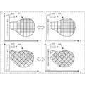
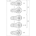
- FIG. 2 is a conceptual diagram showing a modeling state by the three-dimensional additive manufacturing system according to the present embodiment.
- the moving direction X of the squeezing blade 210 for laying the laminated material on the upper layer of the layered object the scanning direction of the cell region in the two layers for the laminated material, and
- the scanning directions 221 to 224 of the cell region in one layer are illustrated, the present invention is not limited to this.
- the upper part of FIG. 2 shows the change in the scanning direction of the rectangular cell regions aligned at right angles (or horizontally) with the moving direction X of the squeezing blade 210.
- the scanning direction 221 of the cell region is a scanning direction of 45 degrees with respect to the moving direction X of the squeezing blade 210, and is one layer in which the scanning direction changes for each cell region.
- the cell region scanning direction 222 is a scanning direction of 45 degrees with respect to the moving direction X of the squeezing blade 210, and is another layer in which the scanning direction changes for each cell region.
- the scanning direction 221 of the cell region and the scanning direction 222 of the cell region are different from each other, and it is possible to suppress the projection from being generated in the upper layer of the modeled object following the same scanning direction.
- the lower part of FIG. 2 shows the change in the scanning direction of the rectangular cell regions arranged at an inclination of 45 degrees with the moving direction X of the squeezing blade 210.
- the scanning direction 223 of the cell region is parallel to the rectangular side of the cell region, but the scanning direction is 45 degrees with respect to the moving direction X of the squeezing blade 210, and the scanning direction changes for each cell region. Is a layer.
- the cell region scanning direction 224 is a scanning direction of 45 degrees with respect to the moving direction X of the squeezing blade 210, and is another layer in which the scanning direction changes for each cell region.
- the scanning direction 223 of the cell region and the scanning direction 224 of the cell region are different from each other in the scanning direction of the cell region, and the same scanning direction continues to suppress the formation of a protrusion on the upper layer of the modeled object. It will be.
- FIG. 2 an example of a scanning direction of 45 degrees with respect to the moving direction X of the squeezing blade 210 is shown, but an acute angle ( ⁇ 90 degrees) with respect to the moving direction X of the squeezing blade 210. It is desirable that the difference between the scanning directions of the cell regions in the two layers need not be 90 degrees.
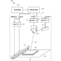
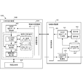
- FIG. 3 is a block diagram illustrating a functional configuration of the additive manufacturing unit 310 in the three-dimensional additive manufacturing system 300 according to the present embodiment.
- the three-dimensional additive manufacturing system 300 includes an additive manufacturing unit 310, an additive manufacturing control unit 320, and an information processing device 330.
- the additive manufacturing unit 310 generates a three-dimensional additive manufacturing object according to various control commands of the additive manufacturing control unit 320.
- the layered modeling control unit 320 generates various control commands for controlling the layered modeling unit 310 according to the three-dimensional modeling data generated by the information processing device 330.
- the control command includes an irradiation command for controlling the irradiation unit 312 by the irradiation amplifier 311, a scanning command for controlling the operation direction by the scanning amplifier 313 via the rotary step motor 314, the squeezing blade 210 and the modeling And a movement command for controlling the movement of the table 318.
- the information processing apparatus 330 acquires information on the layered object to be three-dimensionally shaped and generates three-dimensional modeling data. Note that the information processing apparatus 330 may be a general-purpose computer or a special computer corresponding to the present embodiment.
- the laminate modeling unit 310 includes an irradiation amplifier 311 and an irradiation unit 312.
- the layered modeling part 310 includes a scanning amplifier 313, a rotary step motor 314, and a mirror part 315.
- the layered modeling unit 310 includes a movement amplifier 317, a squeezing blade 210, and a modeling table 318.
- the laser beam 316 emitted from the irradiation unit 312 is formed on the modeling table 318 by the mirror unit 315 rotated by the rotary step motor 314, and the modeling object 220 is already layered.
- a modeling surface is generated as a set of cell regions that are irradiated on the upper surface of the substrate in different scanning directions.
- a three-dimensional layered object is generated.
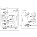
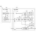
- FIG. 4 is a block diagram illustrating a functional configuration of the additive manufacturing control unit 320 in the three-dimensional additive manufacturing system 300 according to the present embodiment. 4, functional configurations of the additive manufacturing control unit 320 and the information processing apparatus 330 in FIG. 3 are shown.
- the layered modeling unit 310 and the layered modeling control unit 320 may constitute a three-dimensional modeling apparatus 420, a so-called 3D printer.
- the structure of the layered modeling part 310 is the same as that of FIG. 3, and the overlapping description is omitted.
- the three-dimensional modeling apparatus 420 including the additive manufacturing control unit 320 and the information processing apparatus 330 are illustrated as separate apparatuses, but the additive manufacturing control unit 320 may be configured as one apparatus. May be combined with the information processing apparatus 330.
- the additive manufacturing control unit 320 includes a communication control unit 421, a three-dimensional modeling data storage unit 422, a cell shape determination unit 423, a scanning pattern database 424, a scanning direction selection unit 425, and an additive manufacturing command unit 426. Prepare.
- the communication control unit 421 controls communication between the additive manufacturing control unit 320 and the information processing device 330, receives 3D modeling data, instruction commands, and the like from the information processing device 330, or includes an additive manufacturing control unit 320 and the status of the layered modeling part 310 are transmitted to the information processing apparatus 330.
- the three-dimensional modeling data storage unit 422 stores the three-dimensional modeling data received from the information processing device 330.
- the storage of the three-dimensional modeling data may be a unit of a three-dimensional modeled object or a layer unit to be stacked, or a layered modeling speed of the three-dimensional modeling apparatus 420, a processing speed of the information processing apparatus 330, or This is appropriately determined based on the communication capacity between the information processing device 330 and the additive manufacturing control unit 320.
- the cell shape determining unit 423 determines the shape of the cell region of the layer formed by the layered modeling unit 310.
- a square shape that is arranged at right angles (or parallel) to the moving direction X of the squeegee blade 210, or that that is inclined 45 degrees with respect to the moving direction X is used.
- It may be a pentagon or more polygon, circle, ellipse or the like. In this embodiment, a case where the cell shape does not change during additive manufacturing will be described.
- the scanning pattern database 424 is a combination of scanning directions in the cell region that is preferably used without the squeezing blade 210 being caught by the modeling object based on the characteristics of the three-dimensional modeling data, the characteristics of the three-dimensional modeling apparatus, and the layered modeling conditions. As a result, the history of the scanning pattern is accumulated.
- the scanning direction selection unit 425 can suppress the squeezing blade 210 from being caught by the modeled object, based on the three-dimensional modeled data currently being layered modeled.
- the scanning direction of each cell region is selected by predicting the scanning pattern or the scanning pattern of each layer.
- the layered modeling instruction unit 426 issues a command to each unit of the layered modeling unit 310 corresponding to the scanning direction of each cell region selected by the scanning direction selection unit 425.
- the cell shape determination unit 423, the scanning pattern database 424, the scanning direction selection unit 425, and the additive manufacturing command unit 426 constitute all or part of the scanning direction control unit.
- the information processing apparatus 330 may be a general-purpose computer such as a PC (personal computer).
- the information processing apparatus 330 includes a communication control unit 431, a three-dimensional modeling data generation unit 432, a display unit 433, an operation unit 434, a three-dimensional modeling database 435, and a three-dimensional modeling target data acquisition unit 436.
- the 3D modeling target data acquisition unit 436 serves as a 3D modeling target data generation unit.
- the communication control unit 431 controls communication with the 3D modeling apparatus 420 or the 3D modeling target data generation apparatus which is an external device.
- the three-dimensional modeling data generation unit 432 uses the data stored in the three-dimensional modeling database 435 according to the input or operation by the operator from the operation unit 434 according to the operation instruction displayed on the display unit 433, and the three-dimensional modeling apparatus 420. Generates 3D modeling data for layered modeling of a 3D modeling object.
- the display unit 433 notifies the status of the three-dimensional modeling apparatus 420 and the information processing apparatus 330 and requests the operator to input parameters necessary for the layered modeling of the three-dimensional modeled object.
- the operation unit 434 includes a keyboard, a pointing device, a touch panel, and the like, and accepts an input and an operation instruction from an operator according to an instruction displayed on the display unit 433.
- the three-dimensional modeling database 435 stores data of a three-dimensional modeling object, a generation algorithm, a generation parameter, and the like, which are data used by the three-dimensional modeling data generation unit 432 to generate three-dimensional modeling data.
- the 3D modeling target data acquisition unit 436 acquires the 3D modeling target data provided from the 3D modeling target data generation apparatus via the communication control unit 431 or from a storage medium or the like via the I / O interface. To do.
- FIG. 5 is a block diagram illustrating a functional configuration of the scanning direction selection unit 425 according to the present embodiment.
- the scanning direction selection unit 425 includes a cell shape reception unit 501, a three-dimensional modeling data reception unit 502, a scanning direction acquisition unit 503, and a scanning direction output unit 504.
- the cell shape receiving unit 501 receives the cell shape determined from the cell shape determining unit 423. In the present embodiment, a square shape that is arranged at right angles (or parallel) to the moving direction X of the squeegee blade 210, or that that is inclined 45 degrees with respect to the moving direction X is used.
- the three-dimensional modeling data receiving unit 502 receives the three-dimensional modeling data currently being layered from the three-dimensional modeling data storage unit 422.
- the scanning direction acquisition unit 503 takes the cell shape received by the cell shape receiving unit 501 based on the 3D modeling data received by the 3D modeling data receiving unit 502 from the scanning pattern database 424, and the squeezing blade 210. Is acquired in the scanning direction of each cell region that can be suppressed from being caught by the modeled object.
- the scanning direction output unit 504 outputs the scanning direction of each cell region to the additive manufacturing command unit 426.
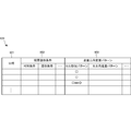
- FIG. 6 is a diagram showing a configuration of the scanning pattern database 424 according to the present embodiment.
- the scanning pattern database 424 is a combination of scanning directions in the cell region that is preferably used without the squeezing blade 210 being caught by the modeling object based on the characteristics of the three-dimensional modeling data, the characteristics of the three-dimensional modeling apparatus, and the additive manufacturing conditions. As a result, the history of the scanning pattern is accumulated.
- the scanning pattern database 424 is referred to by the scanning direction selection unit 425 to select the scanning direction of the cell region.
- the scan pattern database 424 is not limited to the configuration shown in FIG.
- the scanning pattern database 424 accumulates the history of the layered modeling condition 602 and the scanning direction change pattern 603 in association with the date and time 601 when the layered modeling scanning pattern is acquired.
- the layered modeling condition 602 a layered material, a modeled condition, and the like are stored.
- the additive manufacturing condition 602 includes the characteristics of the three-dimensional modeling apparatus 420 and the characteristics of the three-dimensional modeling data.
- the scan direction change pattern 603 stores a used cell shape change pattern, a scan change pattern in a cell region, and the like.
- the scan change pattern in the cell area is, for example, a change pattern that repeats the change in the scan direction of the same cell position for each layer, or a change pattern that repeats the change in the scan direction of the same cell position for each layer.
- a change pattern, a random change pattern, or the like may be included.
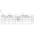
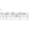
- FIG. 7 is a diagram showing a configuration of the scanning direction selection table 700 according to the present embodiment.
- the scanning direction selection table 700 is used by the scanning direction selection unit 425 to select the scanning direction of the cell region with reference to the scanning pattern database 424.
- the scanning direction selection table 700 is associated with the ID 701 of the three-dimensional modeling data stored in the three-dimensional modeling data storage unit 422, and the scanning direction 703 selected based on the layered modeling condition 702 and the layered modeling condition 702,
- the layered modeling condition 702 a layered material, a modeled condition, and the like are stored.
- the additive manufacturing condition 702 includes the characteristics of the three-dimensional modeling apparatus 420 and the characteristics of the three-dimensional modeling data.
- the selected scanning direction 703 includes a cell shape change pattern and an intra-cell scanning direction change pattern acquired (predicted) from the scanning pattern database 424 based on the layered modeling condition 702.
- FIG. 8 is a diagram showing a configuration of the additive manufacturing command table 800 according to the present embodiment.
- the additive manufacturing command table 800 is used by the additive manufacturing command unit 426 to generate a command (command) to be transmitted to the additive manufacturing unit 310 corresponding to the scanning direction of each cell region selected by the scanning direction selection unit 425. Is done.
- the layered modeling command table 800 stores the layered positions 802 in order from the lower layer in this example in association with the ID 801 of the three-dimensional modeling data stored in the three-dimensional modeling data storage unit 422. And about each lamination
- the cell information 804 the cell shape of each cell region, the scanning direction of irradiation in the cell region, and the like are stored.
- the stacking position 802 may not be stored. Further, when only the cell area to be modeled is stored as the three-dimensional modeling data 803, a flag indicating whether or not to model is not required.
- the cell shape in the cell information 804 is fixed, and the scanning direction is an angle with the moving direction of the squeezing blade 210 (for example, 45 degrees), but is different from a change in cell shape or a straight line. It may be a scanning pattern.
- FIG. 9 is a block diagram illustrating a hardware configuration of the additive manufacturing control unit 320 according to the present embodiment.
- a CPU (Central Processing Unit) 910 is a processor for arithmetic control, and implements a functional component of the additive manufacturing control unit 320 of FIG. 4 by executing a program.
- a ROM (Read Only Memory) 920 stores initial data and fixed data such as a program.
- the communication control unit 421 communicates with the information processing device 330 via a network or the like. Note that the number of CPUs 910 is not limited to one, and may be a plurality of CPUs or may include a GPU (Graphics Processing Unit) for image processing.
- the processor for determining the cell shape and selecting the scanning direction based on the received three-dimensional modeling data and the processor for generating various commands for controlling the scanning of irradiation in the cell region are different.
- the communication control unit 421 preferably includes a CPU independent of the CPU 910 and writes or reads transmission / reception data in a RAM (Random Access Memory) 940 area.
- a DMAC Direct Memory Access Control
- the CPU 910 recognizes that the data has been received or transferred to the RAM 940 and processes the data. Further, the CPU 910 prepares the processing result in the RAM 940 and leaves the subsequent transmission or transfer to the communication control unit 421 or the DMAC.
- the RAM 940 is a random access memory that the CPU 910 uses as a work area for temporary storage. In the RAM 940, an area for storing data necessary for realizing the present embodiment is secured.
- the three-dimensional modeling data 941 is data of a three-dimensional model that is currently layered.
- the cell information 942 is information that defines a cell region for layered modeling of the three-dimensional modeling data 941.
- the scanning direction selection table 700 is a table for the scanning direction selection unit 425 described in FIG. 7 to select a scanning direction in the cell region.
- the additive manufacturing command table 800 is a table for generating an instruction for instructing the additive manufacturing unit 310 to irradiate the inside of the cell region in the scanning direction selected by the additive manufacturing command unit 426 described in FIG.
- the transmission / reception data 943 is data transmitted / received via the communication control unit 421.
- the storage 950 stores a database, various parameters, or the following data or programs necessary for realizing the present embodiment.
- the scanning pattern database 424 is a cell in which the squeezing blade 210 is suitably used without being caught by the modeling object based on the three-dimensional modeling data, the characteristics of the three-dimensional modeling apparatus and the additive manufacturing conditions described in FIG. A history of scanning patterns is accumulated as a combination of scanning directions in the region. Then, the scanning direction selection unit 425 refers to select the scanning direction of the cell region.
- the three-dimensional modeling data 951 is data for layered modeling of a three-dimensional modeled object received from the information processing device 330 via the communication control unit 421 and stored.
- the layered modeling command generation algorithm 952 is an algorithm for generating a command for controlling the layered modeling unit 310 based on the three-dimensional modeling data 941 and the cell position and the scanning direction of the cell region.
- the storage 950 stores the following programs.
- the additive manufacturing control unit control program 953 is a control program that controls the entire additive manufacturing control unit 320.
- the three-dimensional modeling data acquisition module 954 is a module that communicates with the information processing apparatus 330 and acquires three-dimensional modeling data.
- the scanning direction selection module 955 is a module in which the scanning direction selection unit 425 refers to the scanning pattern database 424 and predicts the scanning direction of the cell region so that the squeezing blade 210 is not caught by the modeled object.
- the layered modeling command generation module 956 is a module that generates various commands for controlling the layered modeling unit 310 based on the scanning direction in each cell region selected by the scanning direction selection module 955.
- RAM 940 and the storage 950 in FIG. 9 do not show programs and data related to general-purpose functions and other realizable functions that the additive manufacturing control unit 320 has.
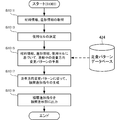
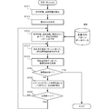
- FIG. 10A is a flowchart illustrating a processing procedure of the additive manufacturing control unit 320 according to the present embodiment. This flowchart is executed by the CPU 910 in FIG. 9 using the RAM 940, and realizes a functional configuration unit of the additive manufacturing control unit 320 in FIG.
- the layered modeling control unit 320 receives and stores the three-dimensional modeling data from the information processing apparatus 330 in step S1001.
- step S ⁇ b> 1003 the layered modeling control unit 320 predicts the scanning direction of the cell region so that the squeezing blade 210 is not caught on the modeled object based on the acquired three-dimensional modeling data.
- a modeling command generation process is executed.
- step S ⁇ b> 1005 the layered modeling control unit 320 transmits the generated layered modeling command to the layered modeling unit 310 and executes the layered modeling process of the three-dimensional modeled object.
- FIG. 10B is a flowchart illustrating a procedure of the additive manufacturing command generation process (S1003) according to the present embodiment.
- the layered modeling control unit 320 acquires information used for selection of the scanning direction, such as material information for layered modeling and information on a modeled object, in step S1011.
- the additive manufacturing control unit 320 determines the shape and size of the cell region to be used.
- the cell to be used is the same during one layered manufacturing.
- the additive manufacturing control unit 320 refers to the scanning pattern database 424 based on the information used for selecting the scanning direction acquired in step S1011 and the used cell determined in step S1013 in step S1015. The change pattern in the scanning direction in the cell region during the additive manufacturing is predicted.
- step S1017 the layered modeling control unit 320 generates a layered modeling command for controlling the layered modeling unit 310 according to the scanning direction change pattern in the cell region selected in step S1015. Then, the layered modeling control unit 320 outputs the generated layered modeling command to the layered modeling unit 310 in step S1019.
- the present embodiment by predicting the scanning direction of the irradiation unit with respect to the moving direction of the squeezing blade during modeling of each layer or based on three-dimensional modeling data so as to change between layers.
- the squeezing blade can be restrained in advance from being caught on the three-dimensionally modeled object.
- the three-dimensional additive manufacturing system according to the present embodiment is different from the second embodiment in that the scanning direction by the irradiation unit is changed every time a predetermined number of layers are stacked. Since other configurations and operations are the same as those of the second embodiment, the same configurations and operations are denoted by the same reference numerals, and detailed description thereof is omitted. For example, since the configuration of the scanning pattern database and the configuration of the additive manufacturing command table are the same as those in the second embodiment, detailed description thereof is omitted.
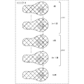
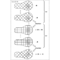
- FIG. 11 is a conceptual diagram showing a modeling state by the three-dimensional additive manufacturing system according to the present embodiment.
- the moving direction X of the squeezing blade 210 for spreading the laminated material on the upper layer of the layered object and the scanning direction of the cell region in the n layer for the laminated material are shown.
- the change in the scanning direction of the rectangular cell regions arranged at an inclination of 45 degrees with the moving direction X of the squeezing blade 210 is shown, but the angle is not limited to this.
- n layers (layers 1 to (n-1)) in the upper stage 1101 in FIG. 11 show the change in the scanning direction of the rectangular cell regions aligned with the moving direction X of the squeezing blade 210 at an inclination of 45 degrees. . Since the scanning direction of each cell region is parallel to the rectangular side of the cell region, the scanning direction is 45 degrees with respect to the moving direction X of the squeezing blade 210, and the scanning direction changes for each cell region in each layer. Shows the layer.
- n layer (n layer to (2n-1) layer) in the middle stage 1102 in FIG. 11 is a rectangular cell region aligned with the moving direction X of the squeezing blade 210 at an inclination of 45 degrees as in the upper stage 1101. This indicates that the scanning directions are different in each cell region at the same position.
- the lower 2n-th layer in FIG. 11 is a rectangular cell region arranged at an inclination of 45 degrees with the moving direction X of the squeezing blade 210, as in the upper step 1101, and each cell region at the same position in the scanning direction Indicates that the scanning direction is the same as that of the upper stage 1101.
- FIG. 11 shows an example in which the scanning direction of the cell region is changed for each n layer.
- a cell region whose scanning direction is changed may be selected with reference to a cell position in the three-dimensional structure.
- the scanning directions inclined by 45 degrees with respect to the moving direction X of the squeezing blade 210 are alternately used, but the present invention is not limited to this. Any angle different from the moving direction X of the squeezing blade 210 may be used. In this case, the upper 1101 and the lower 2n-th layer do not have the same scanning direction.
- FIG. 12 is a block diagram illustrating a functional configuration of the scanning direction selection unit 1225 according to the present embodiment.
- the same reference numerals are assigned to functional elements similar to those in FIG.
- the scanning direction acquisition unit 1203 The scanning direction in the cell region is acquired in consideration of information indicating n-layer modeling from the number determination unit 1205.
- the number-of-stacks determination unit 1205 generates information indicating n-layer modeling from the three-dimensional modeling data received by the three-dimensional modeling data receiving unit 502 (that is, Mod n).
- FIG. 13 is a diagram showing the configuration of the scanning direction selection table 1300 according to this embodiment.
- the scanning direction selection table 1300 is used by the scanning direction selection unit 1225 to refer to the scanning pattern database 424 and select the scanning direction of the cell region for each stack number.
- the same components as those in FIG. 7 are denoted by the same reference numerals, and redundant description is omitted.
- the scanning direction selection table 1300 is associated with the three-dimensional modeling data ID 701 stored in the three-dimensional modeling data storage unit 422, and includes a layered modeling condition 702, a number of layers 1304 for changing the scanning direction, and a layered modeling condition 702.
- the scanning direction 1303 selected on the basis of the number of stacked layers 1304 is stored.
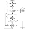
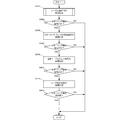
- FIG. 14 is a flowchart showing the procedure of the additive manufacturing command generation process (S1003) according to the present embodiment.
- the same steps as those in FIG. 10B are denoted by the same step numbers, and redundant description is omitted.
- step S1415 the additive manufacturing control unit 320 refers to the scan pattern database 424 based on the information used for selecting the scanning direction acquired in step S1011 and the use cell determined in step S1013, and the n layers A change pattern in the scanning direction in the cell area is predicted.
- step S ⁇ b> 1417 the layered modeling control unit 320 generates one layer of layered modeling command based on the predicted scanning direction change pattern.
- the layered modeling control unit 320 determines whether or not the layered modeling of the three-dimensional modeled object has been completed in step S1421. If the additive manufacturing of the three-dimensional object is completed, the additive manufacturing command generation process is ended. If the layered modeling of the three-dimensional modeled object is not completed, the layered modeling control unit 320 determines whether the number of layers is a multiple of n in step S1423. If the number of layers is not a multiple of n, the layered modeling control unit 320 returns to step S1417 and generates a layered modeling command for the next layer.
- the layered modeling control unit 320 returns to step S1415 and predicts the next n-layer scanning direction change pattern.
- the squeezing blade is pulled onto a three-dimensional shaped object by simple control. It can be suppressed in advance.
- the three-dimensional additive manufacturing system according to the present embodiment is different from the second embodiment or the third embodiment in that the position of the cell region is changed every time a predetermined number of layers are stacked.
- Other configurations and operations are the same as those in the second embodiment and the third embodiment. Therefore, the same configurations and operations are denoted by the same reference numerals, and detailed description thereof is omitted.
- FIG. 15A is a conceptual diagram showing a modeling state by the three-dimensional additive manufacturing system according to the present embodiment.
- the moving direction X of the squeezing blade 210 for spreading the laminated material on the upper layer of the layered object and the scanning direction of the cell region in the m layer for the laminated material are shown.
- the change in the scanning direction of the rectangular cell regions arranged at an inclination of 45 degrees with the moving direction X of the squeezing blade 210 is shown, but the angle is not limited to this.
- the m layer (1st layer to (m-1) layer) in the upper stage 1511 of FIG. 15A shows the change in the scanning direction of the rectangular cell region aligned with the moving direction X of the squeezing blade 210 at an inclination of 45 degrees. . Since the scanning direction of each cell region is parallel to the rectangular side of the cell region, the scanning direction is 45 degrees with respect to the moving direction X of the squeezing blade 210, and in each layer, the scanning direction changes for each cell region. Shows the layer.
- the m layer (m layer to (2m-1) layer) in the middle stage 1512 of FIG. 15A is a rectangular cell in which the cell shape is aligned with the moving direction X of the squeezing blade 210 at an inclination of 45 degrees as in the upper stage 1511. Although it is an area
- the lower 2m-th layer in FIG. 15A is a rectangular cell region aligned with the moving direction X of the squeezing blade 210 at an inclination of 45 degrees as in the upper step 1511.
- Each cell region at the same position in the scanning direction is also shown in FIG. Indicates that the scanning direction is the same as that of the upper stage 1511.
- FIG. 15A shows an example in which the scanning direction is changed by changing the position of the cell region for each m layer.
- 15A shows an example in which the movement of the cell area is a movement of only half of the cell area in the movement direction X of the squeegee blade 210, the movement amount is not limited to half.
- the moving direction is not limited to the moving direction X of the squeezing blade 210, and any movement of the cell region where the scanning direction changes at the same position (X, Y coordinate) of the laminated material may be used.
- the scanning directions inclined by 45 degrees with respect to the moving direction X of the squeezing blade 210 are alternately used, but the present invention is not limited to this. Any angle different from the moving direction X of the squeezing blade 210 may be used. In this case, the upper stage 1511 and the lower 2m-th layer do not have the same scanning direction.
- FIG. 15B is a conceptual diagram showing another modeling state by the three-dimensional additive manufacturing system according to the present embodiment.
- the moving direction X of the squeezing blade 210 for laying the laminated material on the upper layer of the layered object and the scanning direction of the cell region in the m layer for the laid laminated material are illustrated.
- FIG. 15B shows a change between a rectangular cell region arranged at an inclination of 45 degrees with the moving direction X of the squeezing blade 210 and a rectangular cell area arranged at 90 degrees (parallel). The angle is not limited to this.
- the m layer (layer 1 to (m ⁇ 1) layer) in the upper stage 1521 in FIG. 15B shows the change in the scanning direction of the rectangular cell region aligned with the moving direction X of the squeezing blade 210 at an inclination of 45 degrees. . Since the scanning direction of each cell region is parallel to the rectangular side of the cell region, the scanning direction is 45 degrees with respect to the moving direction X of the squeezing blade 210, and in each layer, the scanning direction changes for each cell region. Shows the layer.
- the m layer (m layer to (2m-1) layer) in the middle stage 1522 of FIG. 15B is a cell region having a different rectangular shape in which the cell shape is aligned 90 degrees (parallel) with the moving direction X of the squeezing blade 210. A change in the scanning direction due to the difference in the shape of the cell region is shown.
- the lower 2m-th layer in FIG. 15B is a rectangular cell region aligned with the moving direction X of the squeezing blade 210 at an inclination of 45 degrees as in the upper step 1521.
- Each cell region in the same position in the scanning direction is also shown in FIG. Indicates that the scanning direction is the same as that of the upper stage 1521.
- FIG. 15B shows an example in which the scanning direction is changed by changing the shape (orientation) of the cell region for each m layer.
- 15A shows an example in which the movement of the cell area is a 45-degree rotation of the cell area in the moving direction X of the squeegee blade 210, but the rotation amount is not limited to 45 degrees.
- the scanning directions inclined by 45 degrees with respect to the moving direction X of the squeegee blade 210 are alternately used, but the present invention is not limited to this. Any angle different from the moving direction X of the squeezing blade 210 may be used. In this case, the upper stage 1521 and the lower 2m-th layer do not have the same scanning direction.
- the scanning direction is changed by moving the cell region in FIG. 15A and changing the cell shape (orientation) in FIG. 15B
- the scanning direction may be changed by changing the cell size, or the same position ( Other processing for changing the scanning direction in (X, Y coordinates) may also be included.
- FIG. 16A is a block diagram illustrating a functional configuration of the additive manufacturing control unit 1620 in the three-dimensional additive manufacturing system 1600 according to the present embodiment.
- the same functional components as those in FIG. 4 are denoted by the same reference numerals, and redundant description is omitted.
- a three-dimensional modeling apparatus 1650 including a layered modeling control unit 1620 is shown.
- the cell shape determination unit 1623 refers to the cell shape usage history stored in the cell shape database 1627 and changes the cell shape during additive manufacturing. Note that the cell shape change includes movement and rotation of the cell region, or cell size change.
- the cell shape database 1627 is based on 3D modeling data, characteristics of the 3D modeling apparatus, and additive manufacturing conditions. Accumulate history.
- the configuration of the cell shape database 1627 is similar to that of the scan pattern database 424 except that the accumulation target is different.
- the cell shape database 1627 may be an additive manufacturing history database integrated with the scanning pattern database 424.
- FIG. 16B is a block diagram illustrating a functional configuration of the cell shape determination unit 1623 according to the present embodiment.
- the cell shape determination unit 1623 includes a three-dimensional modeling data reception unit 1601, a stacking number determination unit 1602, a cell position setting unit 1603, a cell shape acquisition unit 1604, and a cell shape output unit 1605.
- the three-dimensional modeling data receiving unit 1601 receives the three-dimensional modeling data from the three-dimensional modeling data storage unit 422.
- the number-of-stacks determination unit 1602 counts the number of layers from the three-dimensional modeling data and notifies that it has become a multiple of “m” (Mod m).
- the cell position setting unit 1603 sets the position of the cell region to change based on the notification from the stack number determination unit 1602 that the stack number has become a multiple of m.
- the change in position includes horizontal (X, Y) movement and rotation.
- the cell shape acquisition unit 1604 changes the cell shape acquired from the cell shape database 1627 in consideration of the three-dimensional modeling data, the number of layers, and the movement and rotation in the horizontal direction (X, Y).
- the cell shape output unit 1605 outputs the cell shape set by the cell shape acquisition unit 1604 to the scanning direction selection unit 425 together with the position thereof.
- FIG. 17 is a diagram showing the configuration of the cell shape determination table 1700 according to this embodiment.
- the cell shape determination table 1700 is used by the cell shape determination unit 1623 with reference to the cell shape database 1627 to determine a cell shape including a cell position for each m layer.
- the cell shape determination table 1700 is associated with the ID 1701 of the 3D modeling data stored in the 3D modeling data storage unit 422, and is based on the layered modeling condition 1702, the number of layers 1703 for changing the cell shape, and the layered modeling condition 1702. And the selected cell shape 1704 is stored.
- the layered modeling condition 1702 a layered material, a modeled condition, and the like are stored.
- the layered modeling condition 1702 includes the characteristics of the three-dimensional modeling apparatus 1650 and the characteristics of the three-dimensional modeling data.
- the selected cell shape 1704 includes a cell shape change pattern and a cell position change pattern (including rotation) acquired (predicted) from the cell shape database 1627 based on the layered manufacturing condition 1702.
- FIG. 18 is a flowchart showing the procedure of the additive manufacturing command generation process (S1003) according to this embodiment.
- S1003 additive manufacturing command generation process
- the additive manufacturing control unit 320 determines a cell shape and a cell size to be used with reference to the cell shape database 1627 in step S1813. Also, the layered modeling control unit 320 refers to the cell shape database 1627 to determine the position of the cell region in step S1814.
- the layered modeling control unit 320 determines whether the number of layers is a multiple of n in step S1423. If the number of layers is not a multiple of n, the layered modeling control unit 320 returns to step S1417 and generates a layered modeling command for the next layer.
- the layered modeling control unit 320 returns to step S1415 and predicts the next n-layer scanning direction change pattern.
- the position or shape of the cell region is changed every time a predetermined number of layers are formed, and the scanning direction of the irradiation unit is changed every time a predetermined number of layers are formed with respect to the moving direction of the squeezing blade.
- the squeegee blade can be prevented from being caught by a layered object by simple control in advance.
- the three-dimensional additive manufacturing system according to the present embodiment changes the scanning direction of the cell region by the irradiation unit when an overload is detected in the driving unit of the squeezing blade, as compared with the second to fourth embodiments. It is different in point. Since other configurations and operations are the same as those in the second to fourth embodiments, the same configurations and operations are denoted by the same reference numerals, and detailed description thereof is omitted.
- FIG. 19 is a conceptual diagram showing a modeling state by the three-dimensional additive manufacturing system according to the present embodiment.
- the moving direction X of the squeezing blade 210 for laying the laminated material on the upper layer of the layered product, and the first i layer and the next j layer for the laminated material are overloaded.
- the present invention is not limited to this.
- the angle is not limited to the change in the scanning direction of the cell region shown in FIG.
- the upper layer 1901 i layer (1st layer to i layer) shows the change in the scanning direction of the rectangular cell region aligned with the moving direction X of the squeezing blade 210 at an inclination of 45 degrees. Since the scanning direction of each cell area is parallel to the rectangular side of the cell area, the scanning direction is 45 degrees with respect to the moving direction X of the squeezing blade 210. In each layer, the scanning direction changes for each cell area. Shows the layer. Here, it is assumed that an overload is detected when the squeezing blade 210 is moved after layered modeling of the i layer.
- the j layer ((i + 1) layer to j layer) in the middle stage 1902 of FIG. 19 has a different cell shape whose cell shape is aligned with the moving direction X of the squeezing blade 210 at 90 degrees (parallel). This shows the change in the scanning direction due to the different cell regions.
- an overload is detected when the squeezing blade 210 after the layered modeling of the j layer is moved.
- the (j + 1) th layer in the lower stage of FIG. 19 is a rectangular cell region arranged at an inclination of 45 degrees with the moving direction X of the squeezing blade 210, as in the upper stage 1901.
- the scanning direction is also the same position. In each cell area, the same scanning direction as that of the upper stage 1901 is shown.
- FIG. 19 shows an example in which the scanning direction in the cell region is changed when an overload is detected when the squeezing blade 210 is moved. Note that the method of changing the scanning direction in the cell region is not limited to FIG. 19, and various methods described in the above embodiment can be used.
- FIG. 20 is a block diagram illustrating a functional configuration of the additive manufacturing control unit 2020 in the three-dimensional additive manufacturing system 2000 according to the present embodiment.
- the same functional elements as those in FIG. 4 are denoted by the same reference numerals, and redundant description is omitted.
- a three-dimensional modeling apparatus 2050 including the layered modeling control unit 2020 is illustrated.
- the layered modeling unit 2010 includes a load detection unit 2011 that detects a moving load of the squeezing blade 210.
- the load detection unit 2011 may be performed by torque detection in a mechanism for moving the squeezing blade 210 or current detection for driving a motor, and is not particularly limited.
- the overload determination unit 2028 of the additive manufacturing control unit 2020 compares the load value detected by the load detection unit 2011 with a threshold value and determines an overload when the threshold value is exceeded.
- the threshold value is selected as a value that can be repaired by changing the scanning direction in the cell region based on the detection value before the squeezing blade 210 is caught by the modeling object and stopping the additive manufacturing, or the change in the detection value.
- the scanning direction selection unit 2025 uses the overload notification output from the overload determination unit 2028 as a trigger in addition to the three-dimensional modeling data, the cell shape, and the scanning pattern from the scanning pattern database 424. To change.
- FIG. 21 is a block diagram illustrating a functional configuration of the scanning direction selection unit 2025 according to the present embodiment.
- the same functional components as those in FIG. 5 are denoted by the same reference numerals, and redundant description is omitted.
- the scanning direction acquisition unit 2103 has an overload determination unit 2028.
- the scanning direction in the cell region is acquired using the overload notification from the trigger.
- FIG. 22 is a diagram showing the configuration of the scanning direction selection table 2200 according to this embodiment.
- the scanning direction selection table 2200 is used by the scanning direction acquisition unit 2103 to acquire the scanning direction in the cell region by using an overload notification as a trigger in addition to the three-dimensional modeling data, the cell shape, and the scanning pattern.
- the same components as those in FIG. 7 are denoted by the same reference numerals, and redundant description is omitted.
- the scanning direction selection table 2200 is associated with the ID 701 of the 3D modeling data stored in the 3D modeling data storage unit 422, the layered modeling condition 702, whether or not an overload is detected 2204, and the layered modeling condition 702. And the scanning direction 2203 selected based on the overload detection as a trigger.
- FIG. 23 is a flowchart showing the procedure of the additive manufacturing command generation process (S1003) according to the present embodiment.
- steps similar to those in FIG. 10B or FIG. 14 are denoted by the same step numbers, and redundant description is omitted.
- the additive manufacturing control unit 2020 selects one scanning direction pattern in step S2315.
- the layered modeling control unit 2020 acquires the load value detected by the drive unit of the squeegee blade 210 in step S2322.
- the additive manufacturing control unit 2020 determines whether or not the detected load value exceeds the threshold value ⁇ in step S2323. If the load value does not exceed the threshold value ⁇ , the additive manufacturing control unit 2020 returns to step S1417 and generates an additive manufacturing command for the next layer. If the load value exceeds the threshold value ⁇ , the additive manufacturing control unit 2020 returns to step S2315 and selects another scanning direction pattern after the overload is detected.
- the squeegee blade when an overload is detected in the drive unit of the squeegee blade, the squeegee blade is efficiently layered and formed by changing the scanning direction of the irradiation unit with respect to the moving direction of the squeegee blade. It is possible to prevent the object from being caught on the object in advance.
- the three-dimensional additive manufacturing system according to the present embodiment predicts the scanning direction of the laminated material in the cell region by the irradiation unit based on the three-dimensional modeling data, and the cell When the overload is detected in the driving unit of the squeezing blade, the scanning direction of the cell region is changed by the irradiation unit. Since other configurations and operations are the same as those in the second to fifth embodiments, the same configurations and operations are denoted by the same reference numerals, and detailed description thereof is omitted.
- FIG. 24 is a block diagram illustrating a functional configuration of the additive manufacturing control unit 2420 in the three-dimensional additive manufacturing system 2400 according to the present embodiment.
- the same functional components as those in FIG. 4 or FIG. In FIG. 24, a three-dimensional modeling apparatus 2450 including a layered modeling control unit 2420 is illustrated.
- the scanning direction selection unit 2425 has the functions of the scanning direction selection unit 425 in FIG. 4 and the scanning direction selection unit 2025 in FIG. That is, the change in the scanning direction of the cell area is determined by prediction, while if it is determined as overload, the change in the scanning direction of the predicted cell area is interrupted and the newly predicted cell area is The process proceeds to changing the scanning direction.
- FIG. 25 is a flowchart showing the procedure of the additive manufacturing command generation process (S1003) according to the present embodiment. In FIG. 25, the same steps as those in FIG. 10B, FIG. 14, or FIG.
- the additive manufacturing control unit 2420 determines whether or not the detected load value exceeds the threshold value ⁇ in step S2323. If the load value does not exceed the threshold value ⁇ , the additive manufacturing control unit 2420 returns to step S1417 and generates an additive manufacturing command for the next layer. If the load value exceeds the threshold value ⁇ , the layered modeling control unit 2420 returns to step S1015 and shifts to a newly predicted change in the scanning direction of the cell region.
- the irradiation unit when the scanning direction of the irradiation unit is predicted based on the three-dimensional modeling data with respect to the moving direction of the squeezing blade, and the overload is detected in the driving unit of the squeezing blade, the irradiation unit is scanned. By changing the direction, it is possible to surely prevent the squeezing blade from being caught by the layered object.
- the three-dimensional additive manufacturing system according to the present embodiment generates the three-dimensional modeling data in consideration of the change in the scanning direction of the laminated material in the cell region by the irradiation unit. The difference is that the scanning direction of the cell region by the irradiation unit is changed. Since other configurations and operations are the same as those in the second to sixth embodiments, the same configurations and operations are denoted by the same reference numerals, and detailed description thereof is omitted.
- FIG. 26 is a block diagram illustrating a functional configuration of the information processing apparatus 2630 in the three-dimensional additive manufacturing system 2600 according to the present embodiment.
- FIG. 26 functional elements similar to those in FIG. 4 or FIG.
- the additive manufacturing control unit 2620 of the 3D modeling apparatus 2650 does not have a function of changing the scanning direction in the cell region, and irradiates in the scanning direction based on the 3D modeling data received from the information processing apparatus 2630. Control only.
- the information processing apparatus 2630 includes a three-dimensional modeling data generation unit 2632, an overload determination unit 2637, a scanning direction pattern database 2638, and a scanning direction selection unit 2639.
- the 3D modeling data generation unit 2632 generates 3D modeling data including information on the scanning direction in the cell region predicted by the scanning direction selection unit 2639.
- the overload determination unit 2637 notifies the overload when the load value transmitted from the load detection unit 2011 of the layered modeling unit 2010 exceeds a threshold value. Similar to the scanning pattern database 424 in FIG. 4, the scanning direction pattern database 2638 is suitable without the squeezing blade 210 being caught by the modeling object based on the three-dimensional modeling data, the characteristics of the three-dimensional modeling apparatus, and the additive manufacturing conditions.
- the scanning direction selection unit 2639 predicts the scanning direction in the cell region based on the three-dimensional modeling target data of the three-dimensional modeled object, the scanning direction pattern of the accumulation history in the scanning direction pattern database 2638, and the overload notification. To do.
- the overload determination unit 2637 is optional and may not be included.
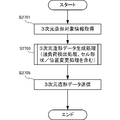
- FIG. 27 is a flowchart showing a processing procedure of the information processing apparatus 2630 according to this embodiment.
- the information processing apparatus 2630 acquires 3D modeling target information in step S2701.
- the information processing device 2630 executes a three-dimensional modeling data generation process including an overload detection process, a cell shape or position change process, and the like.
- generation processing since the information of the scanning direction change in a cell area
- the information processing device 2630 transmits the generated three-dimensional modeling data to the additive manufacturing control unit 2620 of the three-dimensional modeling device 2650.
- the additive manufacturing control unit 2620 controls the additive manufacturing unit 2010 according to the received three-dimensional modeling data, and additively manufactures the three-dimensional object so that the squeezing blade 210 is not caught by the object.
- three-dimensional modeling data is generated in consideration of the change in the scanning direction of the laminated material in the cell region by the irradiation unit, and the three-dimensional shape is changed by changing the scanning direction of the cell region by the irradiation unit. Even without changing the modeling apparatus, it is possible to prevent the squeezing blade from being caught on a modeled object that has been layered.
- the three-dimensional additive manufacturing system according to the present embodiment is different from the second to seventh embodiments in that a change in the laser scanning direction is combined with another process when it is insufficient as an overload countermeasure. Since other configurations and operations are the same as those in the second to seventh embodiments, the same configurations and operations are denoted by the same reference numerals, and detailed description thereof is omitted.
- FIG. 28 is a flowchart illustrating a processing procedure of the information processing apparatus according to the present embodiment.
- step S2801 the information processing apparatus executes at least one of the laser scanning direction changing processes described in the first to seventh embodiments.
- the information processing apparatus measures the load during squeezing and determines whether or not the load is large or whether or not the load is not sufficiently reduced.
- the information processing apparatus performs a process for changing the moving speed of the squeegee blade in step S2805.
- the information processing apparatus measures the load at the time of squeezing and determines whether or not the load is increased, or whether or not the reduction of the load is insufficient.
- step S2811 the information processing apparatus measures the load during squeezing and determines whether or not the load is large or whether or not the load is sufficiently reduced.
- the information processing apparatus performs a process for changing the intensity of the laser beam in step S2813.
- the information processing apparatus measures the load at the time of squeezing and determines whether or not the load is large, or whether or not the reduction of the load is insufficient.
- the information processing apparatus may perform processing to reduce other loads.
- the moving speed of the squeegee blade when changing the moving speed of the squeegee blade, if the load is approaching an overload, the moving speed is reduced so as not to exceed the overload, and if the load is far from the overload, the moving speed is decreased.
- the surface of the layered object may be scraped and flattened.
- the change process of the vertical movement of the modeling table if the load is approaching overload, widen the descent distance so as not to exceed the overload, and reduce the descent distance when the load is away from the overload.
- the surface of the layered object may be cut and flattened.
- the intensity of the laser beam is lowered so as not to exceed the overload, and if the load is far from the overload, the intensity of the laser beam is decreased. It is possible to increase the modeling speed of the layered object.
- the present invention may be applied to a system composed of a plurality of devices, or may be applied to a single device. Furthermore, the present invention can also be applied to a case where an information processing program that implements the functions of the embodiments is supplied directly or remotely to a system or apparatus. Therefore, in order to realize the functions of the present invention on a computer, a program installed on the computer, a medium storing the program, and a WWW (World Wide Web) server that downloads the program are also included in the scope of the present invention. . In particular, at least a non-transitory computer readable medium storing a program for causing a computer to execute the processing steps included in the above-described embodiments is included in the scope of the present invention.
Landscapes
- Engineering & Computer Science (AREA)
- Chemical & Material Sciences (AREA)
- Materials Engineering (AREA)
- Manufacturing & Machinery (AREA)
- Physics & Mathematics (AREA)
- Optics & Photonics (AREA)
- Mechanical Engineering (AREA)
- Automation & Control Theory (AREA)
- Human Computer Interaction (AREA)
- General Physics & Mathematics (AREA)
- Plasma & Fusion (AREA)
- Health & Medical Sciences (AREA)
- Toxicology (AREA)
- Powder Metallurgy (AREA)
Abstract
本発明のシステムは、スキージングブレードが積層造形された造形物に引っ掛るのを前もって抑制する3次元積層造形システムである。この3次元積層造形システムは、積層材料を積層造形物の上層に敷き詰めるためのスキージングブレードと積層材料を照射する照射部とを有し、積層造形物の各層をセル領域の集合として造形する積層造形部と、セル領域内の積層材料を照射部が照射する走査方向が、スキージングブレードの移動方向に対して積層造形中に変化するよう、積層造形部を制御する積層造形制御部と、を備える。
Description
本発明は、3次元積層造形における走査方向を制御する技術に関する。
上記技術分野において、特許文献1には、積層造形物を矩形領域に分割して、各矩形領域を異なる走査パターンで照射する技術が開示されている。また、特許文献2には、SLMのガス流に対して斜め45度方向に走査し、層ごとに走査方向を変えて積層造形物の熱収縮による変形を抑制する技術が開示されている。
しかしながら、上記文献に記載の技術は、積層造形物の上層に積層材料を敷き詰めるためのスキージングブレードが積層造形された造形物に引っ掛ることについては考慮されていない。したがって、スキージングブレードが積層造形された造形物に引っ掛るのを前もって抑制することができなかった。そのため、積層造形の中断を防ぐには造形物の上層を削るなどの後処理で対処するしかなかった。
本発明の目的は、上述の課題を解決する技術を提供することにある。
上記目的を達成するため、本発明に係る3次元積層造形システムは、
積層材料を積層造形物の上層に敷き詰めるためのスキージングブレードと前記積層材料を照射する照射手段とを有し、前記積層造形物の各層をセル領域の集合として造形する積層造形手段と、
前記セル領域内の前記積層材料を前記照射手段が照射する走査方向が、前記スキージングブレードの移動方向に対して積層造形中に変化するよう、前記積層造形手段を制御する積層造形制御手段と、
を備える。
積層材料を積層造形物の上層に敷き詰めるためのスキージングブレードと前記積層材料を照射する照射手段とを有し、前記積層造形物の各層をセル領域の集合として造形する積層造形手段と、
前記セル領域内の前記積層材料を前記照射手段が照射する走査方向が、前記スキージングブレードの移動方向に対して積層造形中に変化するよう、前記積層造形手段を制御する積層造形制御手段と、
を備える。
上記目的を達成するため、本発明に係る3次元積層造形方法は、
積層材料を積層造形物の上層に敷き詰めるためのスキージングブレードと前記積層材料を照射する照射手段とを有する積層造形手段を用いて、前記積層造形物の各層をセル領域の集合として造形する積層造形ステップと、
前記セル領域内の前記積層材料を前記照射手段が照射する走査方向が、前記スキージングブレードの移動方向に対して積層造形中に変化するよう、前記積層造形手段を制御する積層造形制御ステップと、
を含む。
積層材料を積層造形物の上層に敷き詰めるためのスキージングブレードと前記積層材料を照射する照射手段とを有する積層造形手段を用いて、前記積層造形物の各層をセル領域の集合として造形する積層造形ステップと、
前記セル領域内の前記積層材料を前記照射手段が照射する走査方向が、前記スキージングブレードの移動方向に対して積層造形中に変化するよう、前記積層造形手段を制御する積層造形制御ステップと、
を含む。
上記目的を達成するため、本発明に係る積層造形制御装置は、
積層造形の対象となる積層造形物のデータを取得するデータ取得手段と、
前記積層造形物の各層をセル領域の集合として造形する積層造形手段において、積層造形中に、前記セル領域内の積層材料を照射する走査方向が、前記積層材料を前記積層造形物の上層に敷き詰めるためのスキージングブレードの移動方向に対して変化するよう、前記積層造形物のデータに基づいて前記積層造形手段を制御する走査方向制御手段と、
を備える。
積層造形の対象となる積層造形物のデータを取得するデータ取得手段と、
前記積層造形物の各層をセル領域の集合として造形する積層造形手段において、積層造形中に、前記セル領域内の積層材料を照射する走査方向が、前記積層材料を前記積層造形物の上層に敷き詰めるためのスキージングブレードの移動方向に対して変化するよう、前記積層造形物のデータに基づいて前記積層造形手段を制御する走査方向制御手段と、
を備える。
上記目的を達成するため、本発明に係る積層造形制御装置の制御方法は、
積層造形の対象となる積層造形物のデータを取得するデータ取得ステップと、
前記積層造形物の各層をセル領域の集合として造形する積層造形手段において、積層造形中に、前記セル領域内の積層材料を照射する走査方向が、前記積層材料を前記積層造形物の上層に敷き詰めるためのスキージングブレードの移動方向に対して変化するよう、前記積層造形物のデータに基づいて前記積層造形手段を制御する走査方向制御ステップと、
を含む。
積層造形の対象となる積層造形物のデータを取得するデータ取得ステップと、
前記積層造形物の各層をセル領域の集合として造形する積層造形手段において、積層造形中に、前記セル領域内の積層材料を照射する走査方向が、前記積層材料を前記積層造形物の上層に敷き詰めるためのスキージングブレードの移動方向に対して変化するよう、前記積層造形物のデータに基づいて前記積層造形手段を制御する走査方向制御ステップと、
を含む。
上記目的を達成するため、本発明に係る積層造形制御装置の制御プログラムは、
積層造形の対象となる積層造形物のデータを取得するデータ取得ステップと、
前記積層造形物の各層をセル領域の集合として造形する積層造形手段において、積層造形中に、前記セル領域内の積層材料を照射する走査方向が、前記積層材料を前記積層造形物の上層に敷き詰めるためのスキージングブレードの移動方向に対して変化するよう、前記積層造形物のデータに基づいて前記積層造形手段を制御する走査方向制御ステップと、
を含む。
積層造形の対象となる積層造形物のデータを取得するデータ取得ステップと、
前記積層造形物の各層をセル領域の集合として造形する積層造形手段において、積層造形中に、前記セル領域内の積層材料を照射する走査方向が、前記積層材料を前記積層造形物の上層に敷き詰めるためのスキージングブレードの移動方向に対して変化するよう、前記積層造形物のデータに基づいて前記積層造形手段を制御する走査方向制御ステップと、
を含む。
本発明によれば、スキージングブレードが積層造形された造形物に引っ掛るのを前もって抑制することができる。
以下に、図面を参照して、本発明の実施の形態について例示的に詳しく説明する。ただし、以下の実施の形態に記載されている構成要素は単なる例示であり、本発明の技術範囲をそれらのみに限定する趣旨のものではない。本明細書で使用される文言“セル領域”は、3次元積層造形において各層の造形領域を微細に分割した領域を示す(例えば、0.1mm四方の矩形など)。本実施形態の3次元積層造形システムは、このセル領域内を種々の走査パターンで照射することにより、セル領域の集合として各層の造形を実現する。
[第1実施形態]
本発明の第1実施形態としての3次元積層造形システム100について、図1を用いて説明する。3次元積層造形システム100は、積層材料を照射して3次元積層造形を行なうシステムである。
本発明の第1実施形態としての3次元積層造形システム100について、図1を用いて説明する。3次元積層造形システム100は、積層材料を照射して3次元積層造形を行なうシステムである。
図1に示すように、3次元積層造形システム100は、積層造形部101と、積層造形制御部102と、を含む。積層造形部101は、積層材料を積層造形物の上層に敷き詰めるためのスキージングブレード111と積層材料を照射する照射部112とを有し、積層造形物の各層をセル領域113の集合として造形する。積層造形制御部102は、セル領域113内の積層材料を照射部112が照射する走査方向が、スキージングブレード111の移動方向に対して積層造形中に変化するよう、積層造形部101を制御する。
本実施形態によれば、スキージングブレードの移動方向に対して照射部の走査方向を積層造形中に変化させることにより、スキージングブレードが積層造形された造形物に引っ掛るのを前もって抑制することができる。
[第2実施形態]
次に、本発明の第2実施形態に係る3次元積層造形システムによる積層造形について説明する。本実施形態に係る3次元積層造形システムは、積層材料を積層造形物の上層に敷き詰めるためのスキージングブレードの移動方向に対して、3次元造形データに基づいて照射部によるセル領域内の積層材料の走査方向を予測してセル領域ごとに変化させる。
次に、本発明の第2実施形態に係る3次元積層造形システムによる積層造形について説明する。本実施形態に係る3次元積層造形システムは、積層材料を積層造形物の上層に敷き詰めるためのスキージングブレードの移動方向に対して、3次元造形データに基づいて照射部によるセル領域内の積層材料の走査方向を予測してセル領域ごとに変化させる。
《3次元積層造形システムの造形概念》
図2は、本実施形態に係る3次元積層造形システムによる造形状態を示す概念図である。図2においては、簡略化のために、積層材料を積層造形物の上層に敷き詰めるためのスキージングブレード210の移動方向Xと、敷き詰めた積層材料について2つの層におけるセル領域の走査方向、および、1つの層におけるセル領域の走査方向221~224とを図示するが、これに限定されない。
図2は、本実施形態に係る3次元積層造形システムによる造形状態を示す概念図である。図2においては、簡略化のために、積層材料を積層造形物の上層に敷き詰めるためのスキージングブレード210の移動方向Xと、敷き詰めた積層材料について2つの層におけるセル領域の走査方向、および、1つの層におけるセル領域の走査方向221~224とを図示するが、これに限定されない。
図2の上段は、スキージングブレード210の移動方向Xと直角(あるいは、水平)に並んだ矩形のセル領域の走査方向の変化を示している。セル領域の走査方向221は、スキージングブレード210の移動方向Xに対して45度の走査方向であって、セル領域ごとに走査方向が変化する1つの層である。セル領域の走査方向222は、スキージングブレード210の移動方向Xに対して45度の走査方向であって、セル領域ごとに走査方向が変化する他の1つの層である。セル領域の走査方向221とセル領域の走査方向222とは、互いに異なる走査方向となっており、同じ走査方向が続いて造形物の上層に突起部が生成することを、抑制することになる。
図2の下段は、スキージングブレード210の移動方向Xと45度の傾きで並んだ矩形のセル領域の走査方向の変化を示している。セル領域の走査方向223はセル領域の矩形の辺に並行であるが、スキージングブレード210の移動方向Xに対して45度の走査方向であって、セル領域ごとに走査方向が変化する1つの層である。セル領域の走査方向224は、スキージングブレード210の移動方向Xに対して45度の走査方向であって、セル領域ごとに走査方向が変化する他の1つの層である。セル領域の走査方向223とセル領域の走査方向224とは、同じセル領域が互いに異なる走査方向となっており、同じ走査方向が続いて造形物の上層に突起部が生成することを、抑制することになる。
なお、図2においては、スキージングブレード210の移動方向Xに対して45度の走査方向の例を示したが、スキージングブレード210の移動方向Xに対して鋭角(<±90度)であるのが望ましく、2つの層におけるセル領域の走査方向の相違が90度である必要はない。
《積層造形部の機能構成》
図3は、本実施形態に係る3次元積層造形システム300における積層造形部310の機能構成を示すブロック図である。
図3は、本実施形態に係る3次元積層造形システム300における積層造形部310の機能構成を示すブロック図である。
3次元積層造形システム300は、積層造形部310と、積層造形制御部320と、情報処理装置330と、を備える。積層造形部310は、積層造形制御部320の各種の制御指令に従って、3次元積層造形物を生成する。積層造形制御部320は、情報処理装置330が生成した3次元造形データに従って、積層造形部310を制御するための各種の制御指令を生成する。制御指令は、照射用アンプ311により照射部312を制御するための照射指令と、走査用アンプ313により回転ステップモータ314を介して操作方向を制御するための走査指令と、スキージングブレード210や造形テーブル318の移動を制御するための移動指令と、を含む。情報処理装置330は、3次元造形対象の積層造形物の情報を取得して、3次元造形データを生成する。なお、情報処理装置330は、汎用のコンピュータであっても、本実施形態に対応する特殊なコンピュータであってもよい。
積層造形部310は、照射用アンプ311と、照射部312と、を有する。また、積層造形部310は、走査用アンプ313と、回転ステップモータ314と、ミラー部315と、を有する。また、積層造形部310は、移動用アンプ317と、スキージングブレード210と、造形テーブル318と、を有する。
スキージングブレード210の移動方向Xを考慮して、照射部312から放射されるレーザ光316は、回転ステップモータ314により回転するミラー部315により、造形テーブル318上の既に積層造形された造形物220の上面に異なる走査方向で照射するセル領域の集合として、造形面を生成する。1つの層を造形後は、造形テーブル318を所定幅(=層厚)下降させ、スキージングブレード210により次層の積層材料を積層造形物の上層に敷き詰める。かかる動作を3次元造形データに従って繰り返すことにより、3次元積層造形物が生成される。
《積層造形制御部の機能構成》
図4は、本実施形態に係る3次元積層造形システム300における積層造形制御部320の機能構成を示すブロック図である。図4においては、図3の積層造形制御部320と情報処理装置330の機能構成を示す。ここで、積層造形部310と積層造形制御部320とは、3次元造形装置420、いわゆる3Dプリンタを構成してもよい。積層造形部310の構成は図3と同様であり、重複する説明は省略する。なお、図4においては、積層造形制御部320を含む3次元造形装置420と情報処理装置330とを別の装置として図示しているが、1つの装置として構成されても、積層造形制御部320を情報処理装置330に合体させてもよい。
図4は、本実施形態に係る3次元積層造形システム300における積層造形制御部320の機能構成を示すブロック図である。図4においては、図3の積層造形制御部320と情報処理装置330の機能構成を示す。ここで、積層造形部310と積層造形制御部320とは、3次元造形装置420、いわゆる3Dプリンタを構成してもよい。積層造形部310の構成は図3と同様であり、重複する説明は省略する。なお、図4においては、積層造形制御部320を含む3次元造形装置420と情報処理装置330とを別の装置として図示しているが、1つの装置として構成されても、積層造形制御部320を情報処理装置330に合体させてもよい。
積層造形制御部320は、通信制御部421と、3次元造形データ記憶部422と、セル形状決定部423と、走査パターンデータベース424と、走査方向選択部425と、積層造形指令部426と、を備える。
通信制御部421は、積層造形制御部320と情報処理装置330との通信を制御し、情報処理装置330から3次元造形データや指示コマンドなどを情報処理装置330から受信したり、積層造形制御部320や積層造形部310の状況を情報処理装置330へ送信したりする。3次元造形データ記憶部422は、情報処理装置330から受信した3次元造形データを記憶する。なお、3次元造形データの記憶は、3次元造形物単位であったり、積層する層単位であったりしてよく、3次元造形装置420の積層造形速度や情報処理装置330の処理速度、あるいは、情報処理装置330と積層造形制御部320との通信容量などに基づいて、適切に決定される。
セル形状決定部423は、積層造形部310で造形する層のセル領域の形状を決定する。本実施形態においては、例えば、正方形でスキージングブレード210の移動方向Xと直角(あるいは平行)に並んだもの、あるいは、移動方向Xと45度傾いたもの、が使用されるが、これに限定されない。5角形以上の多角形や円、楕円などであってもよい。本実施形態においては、積層造形中にセル形状が変化しない場合について説明する。
走査パターンデータベース424は、3次元造形データや3次元造形装置の特性や積層造形の条件に基づいて、スキージングブレード210が造形物に引っ掛かることなく好適に使用されたセル領域内の走査方向の組み合わせとして、走査パターンの履歴を蓄積する。走査方向選択部425は、現在積層造形中の3次元造形データに基づいて、本実施形態においては、スキージングブレード210が造形物に引っ掛かることを抑制可能な、対象の3次元積層造形物全体の走査パターンの予測、あるいは、各層の走査パターンの予測を行なって、各セル領域の走査方向を選択する。積層造形指令部426は、走査方向選択部425により選択された各セル領域の走査方向に対応して、積層造形部310の各部への指令を行なう。ここで、セル形状決定部423と、走査パターンデータベース424と、走査方向選択部425と、積層造形指令部426と、が走査方向制御部の全てあるいはその一部を構成する。
情報処理装置330は、PC(パーソナルコンピュータ)などの汎用コンピュータでよい。情報処理装置330は、通信制御部431と、3次元造形データ生成部432と、表示部433と、操作部434と、3次元造形データベース435と、3次元造形対象データ取得部436と、を備える。なお、情報処理装置330が3次元造形対象データの生成機能を含む場合、3次元造形対象データ取得部436は3次元造形対象データ生成部となる。
通信制御部431は、外部装置である3次元造形装置420または3次元造形対象データ生成装置との通信を制御する。3次元造形データ生成部432は、表示部433に表示された操作指示に従い操作部434からのオペレータによる入力あるいは操作に従って、3次元造形データベース435に格納されたデータを用いて、3次元造形装置420が3次元造形対象物を積層造形するための3次元造形データを生成する。表示部433は、3次元造形装置420や情報処理装置330の状況を報知すると共に、オペレータに対して3次元造形物の積層造形に必要となるパラメータの入力を要請する。操作部434は、キーボード、ポインティングデバイス、タッチパネルなどを含み、表示部433に表示された指示に従い、オペレータからの入力や操作指示を受け付ける。3次元造形データベース435は、3次元造形データ生成部432が3次元造形データを生成するために用いるデータである、3次元造形対象物のデータや生成アルゴリズム、生成パラメータなどを格納する。3次元造形対象データ取得部436は、3次元造形対象データ生成装置から提供される3次元造形対象データを、通信制御部431を介して、あるいは、記憶媒体などからI/Oインタフェースを介して取得する。
(走査方向選択部)
図5は、本実施形態に係る走査方向選択部425の機能構成を示すブロック図である。
図5は、本実施形態に係る走査方向選択部425の機能構成を示すブロック図である。
走査方向選択部425は、セル形状受信部501と、3次元造形データ受信部502と、走査方向取得部503と、走査方向出力部504と、を備える。セル形状受信部501は、セル形状決定部423から決定されたセル形状を受信する。本実施形態においては、正方形でスキージングブレード210の移動方向Xと直角(あるいは平行)に並んだもの、あるいは、移動方向Xと45度傾いたもの、が使用される。3次元造形データ受信部502は、3次元造形データ記憶部422から現在積層造形中の3次元造形データを受信する。走査方向取得部503は、3次元造形データ受信部502が受信した3次元造形データに基づいて、セル形状受信部501が受信したセル形状を考慮して、走査パターンデータベース424から、スキージングブレード210が造形物に引っ掛かることを抑制可能な各セル領域の走査方向を取得する。走査方向出力部504は、各セル領域の走査方向を積層造形指令部426に出力する。
(走査パターンデータベース)
図6は、本実施形態に係る走査パターンデータベース424の構成を示す図である。走査パターンデータベース424は、3次元造形データや3次元造形装置の特性や積層造形の条件に基づいて、スキージングブレード210が造形物に引っ掛かることなく好適に使用されたセル領域内の走査方向の組み合わせとして、走査パターンの履歴を蓄積する。走査パターンデータベース424は、走査方向選択部425がセル領域の走査方向を選択するために参照する。なお、走査パターンデータベース424は、図6の構成に限定されない。
図6は、本実施形態に係る走査パターンデータベース424の構成を示す図である。走査パターンデータベース424は、3次元造形データや3次元造形装置の特性や積層造形の条件に基づいて、スキージングブレード210が造形物に引っ掛かることなく好適に使用されたセル領域内の走査方向の組み合わせとして、走査パターンの履歴を蓄積する。走査パターンデータベース424は、走査方向選択部425がセル領域の走査方向を選択するために参照する。なお、走査パターンデータベース424は、図6の構成に限定されない。
走査パターンデータベース424は、積層造形の走査パターンを取得した日時601に対応付けて、積層造形条件602と、走査方向変更パターン603との履歴を蓄積する。積層造形条件602としては、積層材料や造形条件などが記憶される。積層造形条件602には、3次元造形装置420の特性や3次元造形データの特徴なども含まれる。走査方向変更パターン603は、使用したセル形状の変更パターンや、セル領域内の走査の変更パターンなどが記憶される。セル領域内の走査の変更パターンには、例えば、各層ごとに同じセル位置の走査方向の変更を繰り返す変更パターン、あるいは、隔層ごとに同じセル位置の走査方向の変更を繰り返す変更パターンなどの繰り返し変更パターンや、ランダムな変更パターンなどを含んでもよい。
(走査方向選択テーブル)
図7は、本実施形態に係る走査方向選択テーブル700の構成を示す図である。走査方向選択テーブル700は、走査方向選択部425が、走査パターンデータベース424を参照してセル領域の走査方向を選択するために使用される。
図7は、本実施形態に係る走査方向選択テーブル700の構成を示す図である。走査方向選択テーブル700は、走査方向選択部425が、走査パターンデータベース424を参照してセル領域の走査方向を選択するために使用される。
走査方向選択テーブル700は、3次元造形データ記憶部422に記憶された3次元造形データのID701に対応付けて、積層造形条件702と、積層造形条件702に基づいて選択された走査方向703と、を記憶する。積層造形条件702としては、積層材料や造形条件などが記憶される。積層造形条件702には、3次元造形装置420の特性や3次元造形データの特徴なども含まれる。選択された走査方向703には、積層造形条件702に基づいて走査パターンデータベース424から取得された(予測された)、セル形状の変更パターンやセル内走査方向の変更パターンが含まれる。
(積層造形指令テーブル)
図8は、本実施形態に係る積層造形指令テーブル800の構成を示す図である。積層造形指令テーブル800は、積層造形指令部426が、走査方向選択部425により選択された各セル領域の走査方向に対応した、積層造形部310に送信する命令(コマンド)を生成するために使用される。
図8は、本実施形態に係る積層造形指令テーブル800の構成を示す図である。積層造形指令テーブル800は、積層造形指令部426が、走査方向選択部425により選択された各セル領域の走査方向に対応した、積層造形部310に送信する命令(コマンド)を生成するために使用される。
積層造形指令テーブル800は、3次元造形データ記憶部422に記憶された3次元造形データのID801に対応付けて、本例では下層から順の積層位置802を記憶する。そして、各積層位置802について、各セル領域における、3次元造形データ803とセル情報804とを記憶する。3次元造形データ803としては、各セル領域のセル位置およびそのセル位置を造形するか否かのフラグなどが記憶される。そして、セル情報804としては、各セル領域のセル形状およびセル領域内における照射の走査方向などが記憶される。
なお、各積層位置802単位に3次元造形データを処理する場合には、積層位置802は記憶しなくてもよい。また、3次元造形データ803として造形するセル領域のみを記憶する場合は、造形するか否かのフラグは必要としない。また、本実施形態においては、セル情報804におけるセル形状は固定であり、走査方向はスキージングブレード210の移動方向との角度(例えば45度)であるが、セル形状の変化や直線とは異なる走査パターンであってもよい。
《積層造形制御部のハードウェア構成》
図9は、本実施形態に係る積層造形制御部320のハードウェア構成を示すブロック図である。
図9は、本実施形態に係る積層造形制御部320のハードウェア構成を示すブロック図である。
図9で、CPU(Central Processing Unit)910は演算制御用のプロセッサであり、プログラムを実行することで図4の積層造形制御部320の機能構成部を実現する。ROM(Read Only Memory)920は、初期データおよびプログラムなどの固定データを記憶する。また、通信制御部421は、ネットワークなどを介して情報処理装置330と通信する。なお、CPU910は1つに限定されず、複数のCPUであっても、あるいは画像処理用のGPU(Graphics Processing Unit)を含んでもよい。特に、受信した3次元造形データに基づいて、セル形状の決定や走査方向の選択をするためのプロセッサと、セル領域内での照射の走査を制御する各種指令を生成するプロセッサとは、別のプロセッサであるのが望ましい。また、通信制御部421は、CPU910とは独立したCPUを有して、RAM(Random Access Memory)940の領域に送受信データを書き込みあるいは読み出しするのが望ましい。また、RAM940とストレージ950との間でデータを転送するDMAC(Direct Memory Access Control)を設けるのが望ましい(図示なし)。この場合、CPU910は、RAM940にデータが受信あるいは転送されたことを認識してデータを処理する。また、CPU910は、処理結果をRAM940に準備し、後の送信あるいは転送は通信制御部421あるいはDMACに任せる。
RAM940は、CPU910が一時記憶のワークエリアとして使用するランダムアクセスメモリである。RAM940には、本実施形態の実現に必要なデータを記憶する領域が確保されている。3次元造形データ941は、現在積層造形されている3次元造形物のデータである。セル情報942は、3次元造形データ941を積層造形するためのセル領域を定義する情報である。走査方向選択テーブル700は、図7において説明された、走査方向選択部425がセル領域内の走査方向を選択するためのテーブルである。積層造形指令テーブル800は、図8において説明された、積層造形指令部426が選択された走査方向でセル領域内を照射するよう積層造形部310に指令する命令を生成するためのテーブルである。送受信データ943は、通信制御部421を介して送受信されるデータである。
ストレージ950には、データベースや各種のパラメータ、あるいは本実施形態の実現に必要な以下のデータまたはプログラムが記憶されている。走査パターンデータベース424は、図6において説明された、3次元造形データや3次元造形装置の特性や積層造形の条件に基づいて、スキージングブレード210が造形物に引っ掛かることなく好適に使用されたセル領域内の走査方向の組み合わせとして、走査パターンの履歴を蓄積する。そして、走査方向選択部425がセル領域の走査方向を選択するために参照する。3次元造形データ951は、情報処理装置330から通信制御部421を介して受信して格納した3次元造形物の積層造形用のデータである。積層造形指令生成アルゴリズム952は、3次元造形データ941と、セル位置およびセル領域の走査方向とに基づいて、積層造形部310を制御する指令を生成するためのアルゴリズムである。
ストレージ950には、以下のプログラムが格納される。積層造形制御部制御プログラム953は、本積層造形制御部320の全体を制御する制御プログラムである。3次元造形データ取得モジュール954は、情報処理装置330と通信して3次元造形データを取得するモジュールである。走査方向選択モジュール955は、走査方向選択部425が、走査パターンデータベース424を参照して、スキージングブレード210が造形物に引っ掛かからないようにセル領域の走査方向を予測するモジュールである。積層造形指令生成モジュール956は、走査方向選択モジュール955が選択した各セル領域内の走査方向に基づいて、積層造形部310を制御する各種指令を生成するモジュールである。
なお、図9のRAM940やストレージ950には、積層造形制御部320が有する汎用の機能や他の実現可能な機能に関連するプログラムやデータは図示されていない。
《積層造形制御部の処理手順》
図10Aは、本実施形態に係る積層造形制御部320の処理手順を示すフローチャートである。このフローチャートは、図9のCPU910がRAM940を使用して実行し、図4の積層造形制御部320の機能構成部を実現する。
図10Aは、本実施形態に係る積層造形制御部320の処理手順を示すフローチャートである。このフローチャートは、図9のCPU910がRAM940を使用して実行し、図4の積層造形制御部320の機能構成部を実現する。
積層造形制御部320は、ステップS1001において、情報処理装置330から3次元造形データを受信して記憶する。積層造形制御部320は、ステップS1003において、取得した3次元造形データに基づいて、スキージングブレード210が造形物に引っ掛かからないようにセル領域の走査方向を予測した、積層造形部310への積層造形指令の生成処理を実行する。積層造形制御部320は、ステップS1005において、生成された積層造形指令を積層造形部310に送信して、3次元造形物の積層造形処理を実行する。
(積層造形指令生成処理)
図10Bは、本実施形態に係る積層造形指令生成処理(S1003)の手順を示すフローチャートである。
図10Bは、本実施形態に係る積層造形指令生成処理(S1003)の手順を示すフローチャートである。
積層造形制御部320は、ステップS1011において、積層造形を行なう材料情報や造形物の情報などの走査方向の選択に使用する情報を取得する。積層造形制御部320は、ステップS1013において、使用するセル領域の形状やサイズなどを決定する。本実施形態においては、1回の積層造形の間、使用するセルは同様である。
次に、積層造形制御部320は、ステップS1015において、ステップS1011で取得した走査方向の選択に使用する情報、および、ステップS1013で決定した使用セルなどに基づいて、走査パターンデータベース424を参照して、積層造形中におけるセル領域内の走査方向の変更パターンを予測する。
積層造形制御部320は、ステップS1017において、ステップS1015で選択されたセル領域内の走査方向の変更パターンに従って、積層造形部310を制御する積層造形指令を生成する。そして、積層造形制御部320は、ステップS1019において、生成した積層造形指令を、積層造形部310に出力する。
本実施形態によれば、スキージングブレードの移動方向に対して照射部の走査方向を各層の造形中に、あるいは、層と層とで変化させるように3次元造形データに基づいて予測することにより、スキージングブレードが積層造形された造形物に引っ掛るのを前もって抑制することができる。
[第3実施形態]
次に、本発明の第3実施形態に係る3次元積層造形システムによる積層造形について説明する。本実施形態に係る3次元積層造形システムは、上記第2実施形態と比べると、所定数の層を積層するごとに照射部による走査方向を変化させる点で異なる。その他の構成および動作は、第2実施形態と同様であるため、同じ構成および動作については同じ符号を付してその詳しい説明を省略する。例えば、走査パターンデータベースの構成や積層造形指令テーブルの構成は、第2実施形態と同様であるため詳しい説明を省略する。
次に、本発明の第3実施形態に係る3次元積層造形システムによる積層造形について説明する。本実施形態に係る3次元積層造形システムは、上記第2実施形態と比べると、所定数の層を積層するごとに照射部による走査方向を変化させる点で異なる。その他の構成および動作は、第2実施形態と同様であるため、同じ構成および動作については同じ符号を付してその詳しい説明を省略する。例えば、走査パターンデータベースの構成や積層造形指令テーブルの構成は、第2実施形態と同様であるため詳しい説明を省略する。
《3次元積層造形システムの造形概念》
図11は、本実施形態に係る3次元積層造形システムによる造形状態を示す概念図である。図11においては、簡略化のために、積層材料を積層造形物の上層に敷き詰めるためのスキージングブレード210の移動方向Xと、敷き詰めた積層材料についてn層におけるセル領域の走査方向とを図示するが、これに限定されない。なお、図11においては、スキージングブレード210の移動方向Xと45度の傾きで並んだ矩形のセル領域の走査方向の変化を示しているが、これに限定されない角度であってもよい。
図11は、本実施形態に係る3次元積層造形システムによる造形状態を示す概念図である。図11においては、簡略化のために、積層材料を積層造形物の上層に敷き詰めるためのスキージングブレード210の移動方向Xと、敷き詰めた積層材料についてn層におけるセル領域の走査方向とを図示するが、これに限定されない。なお、図11においては、スキージングブレード210の移動方向Xと45度の傾きで並んだ矩形のセル領域の走査方向の変化を示しているが、これに限定されない角度であってもよい。
図11の上段1101のn層(1層~(n-1)層)は、スキージングブレード210の移動方向Xと45度の傾きで並んだ矩形のセル領域の走査方向の変化を示している。各セル領域の走査方向はセル領域の矩形の辺に並行なので、スキージングブレード210の移動方向Xに対して45度の走査方向であって、各層ではセル領域ごとに走査方向が変化する、n層を示している。
図11の中段1102のn層(n層~(2n-1)層)は、上段1101と同様に、スキージングブレード210の移動方向Xと45度の傾きで並んだ矩形のセル領域であるが、その走査方向は同じ位置の各セル領域においては異なる走査方向となっていることを示している。
図11の下段の2n番目の層は、上段1101と同様に、スキージングブレード210の移動方向Xと45度の傾きで並んだ矩形のセル領域であり、その走査方向も同じ位置の各セル領域においては、上段1101と同じ走査方向となっていることを示している。
以上のように、図11においては、n層ごとにセル領域の走査方向を変える例を示す。しかしながら、図11のように、全セル領域で走査方向を変える必要は無く、3次元造形物におけるセル位置などを参照して走査方向を変えるセル領域を選択してもよい。また、図11においては、スキージングブレード210の移動方向Xに対して、互いに45度傾いた走査方向を交互に使用したが、これに限定されない。スキージングブレード210の移動方向Xに対して異なる角度であればよい。この場合には、上段1101と下段の2n番目の層とが同じ走査方向とならない。
(走査方向選択部)
図12は、本実施形態に係る走査方向選択部1225の機能構成を示すブロック図である。なお、図12において、図5と同様の機能要素には同じ参照番号を付して、重複する説明を省略する。
図12は、本実施形態に係る走査方向選択部1225の機能構成を示すブロック図である。なお、図12において、図5と同様の機能要素には同じ参照番号を付して、重複する説明を省略する。
走査方向取得部1203は、セル形状受信部501からのセル形状、3次元造形データ受信部502が受信した3次元造形データ、および、走査パターンデータベース424からの走査方向の変更パターンに加えて、積層数判定部1205からのn層造形を示す情報を考慮して、セル領域内の走査方向を取得する。積層数判定部1205は、3次元造形データ受信部502が受信した3次元造形データからn層造形を示す情報を生成する(すなわち、Mod n)。
(走査方向選択テーブル)
図13は、本実施形態に係る走査方向選択テーブル1300の構成を示す図である。走査方向選択テーブル1300は、走査方向選択部1225が、走査パターンデータベース424を参照して、積層数ごとにセル領域の走査方向を選択するために使用される。なお、図13において、図7と同様の構成要素には同じ参照番号を付して、重複する説明を省略する。
図13は、本実施形態に係る走査方向選択テーブル1300の構成を示す図である。走査方向選択テーブル1300は、走査方向選択部1225が、走査パターンデータベース424を参照して、積層数ごとにセル領域の走査方向を選択するために使用される。なお、図13において、図7と同様の構成要素には同じ参照番号を付して、重複する説明を省略する。
走査方向選択テーブル1300は、3次元造形データ記憶部422に記憶された3次元造形データのID701に対応付けて、積層造形条件702と、走査方向を変化させる積層数1304と、積層造形条件702に基づいて積層数1304単位で選択された走査方向1303と、を記憶する。
(積層造形指令生成処理)
図14は、本実施形態に係る積層造形指令生成処理(S1003)の手順を示すフローチャートである。なお、図14において、図10Bと同様のステップには同じステップ番号を付して、重複する説明を省略する。
図14は、本実施形態に係る積層造形指令生成処理(S1003)の手順を示すフローチャートである。なお、図14において、図10Bと同様のステップには同じステップ番号を付して、重複する説明を省略する。
積層造形制御部320は、ステップS1415において、ステップS1011で取得した走査方向の選択に使用する情報、および、ステップS1013で決定した使用セルなどに基づいて、走査パターンデータベース424を参照して、n層中におけるセル領域内の走査方向の変更パターンを予測する。そして、積層造形制御部320は、ステップS1417において、予測された走査方向変更パターンにより1層の積層造形指令を生成する。
積層造形制御部320は、ステップS1421において、3次元造形物の積層造形が終了したか否かを判定する。3次元造形物の積層造形が終了すれば積層造形指令生成処理を終了する。3次元造形物の積層造形が終了でなければ、積層造形制御部320は、ステップS1423において、積層数がnの倍数であるか否かを判定する。積層数がnの倍数でなければ、積層造形制御部320は、ステップS1417に戻って、次の層の積層造形指令を生成する。
積層数がnの倍数であれば、積層造形制御部320は、ステップS1415に戻って、次のn層の走査方向変更パターンを予測する。
本実施形態によれば、スキージングブレードの移動方向に対して照射部の走査方向を所定数の層形成ごとに変化させることにより、簡単な制御によりスキージングブレードが積層造形された造形物に引っ掛るのを前もって抑制することができる。
[第4実施形態]
次に、本発明の第4実施形態に係る3次元積層造形システムによる積層造形について説明する。本実施形態に係る3次元積層造形システムは、上記第2実施形態または第3実施形態と比べると、所定数の層を積層するごとにセル領域の位置を変化させる点で異なる。その他の構成および動作は、第2実施形態および第3実施形態と同様であるため、同じ構成および動作については同じ符号を付してその詳しい説明を省略する。
次に、本発明の第4実施形態に係る3次元積層造形システムによる積層造形について説明する。本実施形態に係る3次元積層造形システムは、上記第2実施形態または第3実施形態と比べると、所定数の層を積層するごとにセル領域の位置を変化させる点で異なる。その他の構成および動作は、第2実施形態および第3実施形態と同様であるため、同じ構成および動作については同じ符号を付してその詳しい説明を省略する。
《3次元積層造形システムの造形概念》
図15Aは、本実施形態に係る3次元積層造形システムによる造形状態を示す概念図である。図15Aにおいては、簡略化のために、積層材料を積層造形物の上層に敷き詰めるためのスキージングブレード210の移動方向Xと、敷き詰めた積層材料についてm層におけるセル領域の走査方向とを図示するが、これに限定されない。なお、図15Aにおいては、スキージングブレード210の移動方向Xと45度の傾きで並んだ矩形のセル領域の走査方向の変化を示しているが、これに限定されない角度であってもよい。
図15Aは、本実施形態に係る3次元積層造形システムによる造形状態を示す概念図である。図15Aにおいては、簡略化のために、積層材料を積層造形物の上層に敷き詰めるためのスキージングブレード210の移動方向Xと、敷き詰めた積層材料についてm層におけるセル領域の走査方向とを図示するが、これに限定されない。なお、図15Aにおいては、スキージングブレード210の移動方向Xと45度の傾きで並んだ矩形のセル領域の走査方向の変化を示しているが、これに限定されない角度であってもよい。
図15Aの上段1511のm層(1層~(m-1)層)は、スキージングブレード210の移動方向Xと45度の傾きで並んだ矩形のセル領域の走査方向の変化を示している。各セル領域の走査方向はセル領域の矩形の辺に並行なので、スキージングブレード210の移動方向Xに対して45度の走査方向であって、各層ではセル領域ごとに走査方向が変化する、m層を示している。
図15Aの中段1512のm層(m層~(2m-1)層)は、セル形状が、上段1511と同様に、スキージングブレード210の移動方向Xと45度の傾きで並んだ矩形のセル領域であるが、そのセル領域の位置が異なる位置となっていることを示している。図15Aにおいては、スキージングブレード210の移動方向Xにセル領域の半分だけ移動している。
図15Aの下段の2m番目の層は、上段1511と同様に、スキージングブレード210の移動方向Xと45度の傾きで並んだ矩形のセル領域であり、その走査方向も同じ位置の各セル領域においては、上段1511と同じ走査方向となっていることを示している。
以上のように、図15Aにおいては、m層ごとにセル領域の位置を変えることにより走査方向を変える例を示す。なお、図15Aにおいては、セル領域の移動がスキージングブレード210の移動方向Xにセル領域の半分だけの移動である例を示したが、移動量は半分に限定されない。また、移動方向もスキージングブレード210の移動方向Xの方向に限定されず、積層材料の同じ位置(X,Y座標)において走査方向が変化するセル領域の移動であればよい。また、図15Aにおいては、スキージングブレード210の移動方向Xに対して、互いに45度傾いた走査方向を交互に使用したが、これに限定されない。スキージングブレード210の移動方向Xに対して異なる角度であればよい。この場合には、上段1511と下段の2m番目の層とが同じ走査方向とならない。
図15Bは、本実施形態に係る3次元積層造形システムによる他の造形状態を示す概念図である。図15Bにおいては、簡略化のために、積層材料を積層造形物の上層に敷き詰めるためのスキージングブレード210の移動方向Xと、敷き詰めた積層材料についてm層におけるセル領域の走査方向とを図示するが、これに限定されない。なお、図15Bにおいては、スキージングブレード210の移動方向Xと45度の傾きで並んだ矩形のセル領域と、90度(平行)に並んだ矩形のセル領域と、の変化を示しているが、これに限定されない角度であってもよい。
図15Bの上段1521のm層(1層~(m-1)層)は、スキージングブレード210の移動方向Xと45度の傾きで並んだ矩形のセル領域の走査方向の変化を示している。各セル領域の走査方向はセル領域の矩形の辺に並行なので、スキージングブレード210の移動方向Xに対して45度の走査方向であって、各層ではセル領域ごとに走査方向が変化する、m層を示している。
図15Bの中段1522のm層(m層~(2m-1)層)は、セル形状が、スキージングブレード210の移動方向Xと90度(平行)に並んだ異なる矩形のセル領域であり、セル領域の形状が異なることによる走査方向の変化を示している。
図15Bの下段の2m番目の層は、上段1521と同様に、スキージングブレード210の移動方向Xと45度の傾きで並んだ矩形のセル領域であり、その走査方向も同じ位置の各セル領域においては、上段1521と同じ走査方向となっていることを示している。
以上のように、図15Bにおいては、m層ごとにセル領域の形状(向き)を変えることにより走査方向を変える例を示す。なお、図15Aにおいては、セル領域の移動がスキージングブレード210の移動方向Xにセル領域の45度の回転である例を示したが、回転量は45度に限定されない。また、図15Bにおいては、スキージングブレード210の移動方向Xに対して、互いに45度傾いた走査方向を交互に使用したが、これに限定されない。スキージングブレード210の移動方向Xに対して異なる角度であればよい。この場合には、上段1521と下段の2m番目の層とが同じ走査方向とならない。
なお、図15Aではセル領域の移動、図15Bではセル形状(向き)の変更により走査方向を変えたが、例えば、セルサイズの変更により走査方向を変えてもよいし、積層材料の同じ位置(X,Y座標)において走査方向を変化させる他の処理も含まれてもよい。
《積層造形制御部の機能構成》
図16Aは、本実施形態に係る3次元積層造形システム1600における積層造形制御部1620の機能構成を示すブロック図である。なお、図16Aにおいて、図4と同様の機能構成には同じ参照番号を付して、重複する説明を省略する。また、図16Aにおいては、積層造形制御部1620を含む3次元造形装置1650として示されている。
図16Aは、本実施形態に係る3次元積層造形システム1600における積層造形制御部1620の機能構成を示すブロック図である。なお、図16Aにおいて、図4と同様の機能構成には同じ参照番号を付して、重複する説明を省略する。また、図16Aにおいては、積層造形制御部1620を含む3次元造形装置1650として示されている。
セル形状決定部1623は、図4のセル形状決定部423と異なり、セル形状データベース1627に蓄積されたセル形状の使用履歴を参照して、積層造形中にセル形状を変更する。なお、セル形状の変更には、セル領域の移動や回転、あるいは、セルサイズの変更も含まれる。セル形状データベース1627は、3次元造形データや3次元造形装置の特性や積層造形の条件に基づいて、スキージングブレード210が造形物に引っ掛かることなく好適に使用されたセル形状の組み合わせとして、セル形状の履歴を蓄積する。なお、セル形状データベース1627の構成は、走査パターンデータベース424と蓄積対象が異なるのみで類似であるので、ここでは重複する説明を省略する。セル形状データベース1627は、走査パターンデータベース424と一体となった、積層造形履歴データベースであってもよい。
(セル形状決定部)
図16Bは、本実施形態に係るセル形状決定部1623の機能構成を示すブロック図である。
図16Bは、本実施形態に係るセル形状決定部1623の機能構成を示すブロック図である。
セル形状決定部1623は、3次元造形データ受信部1601と、積層数判定部1602と、セル位置設定部1603と、セル形状取得部1604と、セル形状出力部1605と、を備える。3次元造形データ受信部1601は、3次元造形データ記憶部422から3次元造形データを受信する。積層数判定部1602は、3次元造形データから積層数をカウントして“m”の倍数になったことを通知する(Mod m)。セル位置設定部1603は、積層数判定部1602からの積層数がmの倍数になった通知に基づいて、セル領域の位置が変化するように設定する。位置の変化には、水平方向(X,Y)の移動や回転などが含まれる。セル形状取得部1604は、セル形状データベース1627から取得したセル形状を、3次元造形データ、積層数、および、水平方向(X,Y)の移動や回転などを考慮して、変化させる。セル形状出力部1605は、セル形状取得部1604が設定したセル形状をその位置と共に走査方向選択部425に出力する。
(セル形状決定テーブル)
図17は、本実施形態に係るセル形状決定テーブル1700の構成を示す図である。セル形状決定テーブル1700は、セル形状決定部1623が、セル形状データベース1627を参照して、m層ごとにセル位置を含むセル形状を決定するために使用する。
図17は、本実施形態に係るセル形状決定テーブル1700の構成を示す図である。セル形状決定テーブル1700は、セル形状決定部1623が、セル形状データベース1627を参照して、m層ごとにセル位置を含むセル形状を決定するために使用する。
セル形状決定テーブル1700は、3次元造形データ記憶部422に記憶された3次元造形データのID1701に対応付けて、積層造形条件1702と、セル形状を変える積層数1703と、積層造形条件1702に基づいて選択されたセル形状1704と、を記憶する。積層造形条件1702としては、積層材料や造形条件などが記憶される。積層造形条件1702には、3次元造形装置1650の特性や3次元造形データの特徴なども含まれる。選択されたセル形状1704には、積層造形条件1702に基づいてセル形状データベース1627から取得された(予測された)、セル形状の変更パターンやセル位置の変更パターン(回転を含む)が含まれる。
(積層造形指令生成処理)
図18は、本実施形態に係る積層造形指令生成処理(S1003)の手順を示すフローチャートである。なお、図18において、図10Bまたは図14と同様のステップには同じステップ番号を付して、重複する説明を省略する。
図18は、本実施形態に係る積層造形指令生成処理(S1003)の手順を示すフローチャートである。なお、図18において、図10Bまたは図14と同様のステップには同じステップ番号を付して、重複する説明を省略する。
積層造形制御部320は、ステップS1813において、セル形状データベース1627を参照して使用するセル形状やセルサイズなどを決定する。また、積層造形制御部320は、ステップS1814において、セル形状データベース1627を参照してセル領域の位置を決定する。
ステップS1421で3次元造形物の積層造形が終了でなければ、積層造形制御部320は、ステップS1423において、積層数がnの倍数であるか否かを判定する。積層数がnの倍数でなければ、積層造形制御部320は、ステップS1417に戻って、次の層の積層造形指令を生成する。
積層数がnの倍数であれば、積層造形制御部320は、ステップS1415に戻って、次のn層の走査方向変更パターンを予測する。
本実施形態によれば、セル領域の位置あるいは形状を所定数の層形成ごとに変化させて、スキージングブレードの移動方向に対して照射部の走査方向を所定数の層形成ごとに変化させることにより、簡単な制御によりスキージングブレードが積層造形された造形物に引っ掛るのを前もって抑制することができる。
[第5実施形態]
次に、本発明の第5実施形態に係る3次元積層造形システムによる積層造形について説明する。本実施形態に係る3次元積層造形システムは、上記第2実施形態から第4実施形態と比べると、スキージングブレードの駆動部において過負荷を検出すると、照射部によるセル領域の走査方向を変化させる点で異なる。その他の構成および動作は、第2実施形態から第4実施形態と同様であるため、同じ構成および動作については同じ符号を付してその詳しい説明を省略する。
次に、本発明の第5実施形態に係る3次元積層造形システムによる積層造形について説明する。本実施形態に係る3次元積層造形システムは、上記第2実施形態から第4実施形態と比べると、スキージングブレードの駆動部において過負荷を検出すると、照射部によるセル領域の走査方向を変化させる点で異なる。その他の構成および動作は、第2実施形態から第4実施形態と同様であるため、同じ構成および動作については同じ符号を付してその詳しい説明を省略する。
《3次元積層造形システムの造形概念》
図19は、本実施形態に係る3次元積層造形システムによる造形状態を示す概念図である。図19においては、簡略化のために、積層材料を積層造形物の上層に敷き詰めるためのスキージングブレード210の移動方向Xと、敷き詰めた積層材料について最初のi層、次のj層で過負荷を検出した場合の、領域の走査方向とを図示するが、これに限定されない。なお、図19に図示されたセル領域の走査方向の変化に限定されない角度であってもよい。
図19は、本実施形態に係る3次元積層造形システムによる造形状態を示す概念図である。図19においては、簡略化のために、積層材料を積層造形物の上層に敷き詰めるためのスキージングブレード210の移動方向Xと、敷き詰めた積層材料について最初のi層、次のj層で過負荷を検出した場合の、領域の走査方向とを図示するが、これに限定されない。なお、図19に図示されたセル領域の走査方向の変化に限定されない角度であってもよい。
図19の上段1901のi層(1層~i層)は、スキージングブレード210の移動方向Xと45度の傾きで並んだ矩形のセル領域の走査方向の変化を示している。各セル領域の走査方向はセル領域の矩形の辺に並行なので、スキージングブレード210の移動方向Xに対して45度の走査方向であって、各層ではセル領域ごとに走査方向が変化する、i層を示している。ここで、i層を積層造形後のスキージングブレード210の移動時に過負荷を検出したものと仮定する。
図19の中段1902のj層((i+1)層~j層)は、図15Bのように、セル形状が、スキージングブレード210の移動方向Xと90度(平行)に並んだ異なる矩形のセル領域であり、セル領域の形状が異なることによる走査方向の変化を示している。ここで、j層を積層造形後のスキージングブレード210の移動時に過負荷を検出したものと仮定する。
図19の下段の(j+1)番目の層は、上段1901と同様に、スキージングブレード210の移動方向Xと45度の傾きで並んだ矩形のセル領域であり、その走査方向も同じ位置の各セル領域においては、上段1901と同じ走査方向となっていることを示している。
以上のように、図19においては、スキージングブレード210の移動時に過負荷を検出すると、セル領域内の走査方向を変える例を示す。なお、セル領域内の走査方向を変える方法は図19に限定されず、上記実施形態に記載した種々の方法が使用できる。
《積層造形制御部の機能構成》
図20は、本実施形態に係る3次元積層造形システム2000における積層造形制御部2020の機能構成を示すブロック図である。なお、図20において、図4と同様の機能要素には同じ参照番号を付して、重複する説明は省略する。また、図20においては、積層造形制御部2020を含む3次元造形装置2050として示されている。
図20は、本実施形態に係る3次元積層造形システム2000における積層造形制御部2020の機能構成を示すブロック図である。なお、図20において、図4と同様の機能要素には同じ参照番号を付して、重複する説明は省略する。また、図20においては、積層造形制御部2020を含む3次元造形装置2050として示されている。
積層造形部2010は、スキージングブレード210の移動負荷を検出する負荷検出部2011を有する。例えば、負荷検出部2011は、スキージングブレード210を移動するための機構内のトルク検出や、モータを駆動する電流検出により行なわれてもよく、特に限定されない。
積層造形制御部2020の過負荷判定部2028は、負荷検出部2011が検出した負荷値を閾値と比較して、閾値を超える場合に過負荷と判定する。なお、閾値は、スキージングブレード210が造形物に引っ掛かって積層造形を停止する以前の検出値や、検出値の変化などから、セル領域内の走査方向を変えることで修復可能な値が選択される。走査方向選択部2025は、3次元造形データ、セル形状、および、走査パターンデータベース424からの走査パターンに加えて、過負荷判定部2028が出力した過負荷通知をトリガとして、セル領域内の走査方向を変更する。
(走査方向選択部)
図21は、本実施形態に係る走査方向選択部2025の機能構成を示すブロック図である。なお、図21において、図5と同様の機能構成には同じ参照番号を付して、重複する説明は省略する。
図21は、本実施形態に係る走査方向選択部2025の機能構成を示すブロック図である。なお、図21において、図5と同様の機能構成には同じ参照番号を付して、重複する説明は省略する。
走査方向取得部2103は、3次元造形データ受信部502からの3次元造形データ、セル形状受信部501からのセル形状、および、走査パターンデータベース424からの走査パターンに加えて、過負荷判定部2028からの過負荷通知をトリガとして、セル領域内の走査方向を取得する。
(走査方向選択テーブル)
図22は、本実施形態に係る走査方向選択テーブル2200の構成を示す図である。走査方向選択テーブル2200は、走査方向取得部2103が、3次元造形データ、セル形状、および、走査パターンに加えて、過負荷通知をトリガとして、セル領域内の走査方向を取得するために使用される。なお、図22において、図7と同様の構成要素には同じ参照番号を付して、重複する説明を省略する。
図22は、本実施形態に係る走査方向選択テーブル2200の構成を示す図である。走査方向選択テーブル2200は、走査方向取得部2103が、3次元造形データ、セル形状、および、走査パターンに加えて、過負荷通知をトリガとして、セル領域内の走査方向を取得するために使用される。なお、図22において、図7と同様の構成要素には同じ参照番号を付して、重複する説明を省略する。
走査方向選択テーブル2200は、3次元造形データ記憶部422に記憶された3次元造形データのID701に対応付けて、積層造形条件702と、過負荷を検出したか否か2204と、積層造形条件702に基づいて過負荷検出をトリガとして選択された走査方向2203と、を記憶する。
(積層造形指令生成処理)
図23は、本実施形態に係る積層造形指令生成処理(S1003)の手順を示すフローチャートである。図23において、図10Bまたは図14と同様のステップには同じステップ番号を付して、重複する説明を省略する。
図23は、本実施形態に係る積層造形指令生成処理(S1003)の手順を示すフローチャートである。図23において、図10Bまたは図14と同様のステップには同じステップ番号を付して、重複する説明を省略する。
積層造形制御部2020は、ステップS2315において、1つの走査方向パターンを選択する。
ステップS1421において、3次元造形物の積層造形が終了でなければ、積層造形制御部2020は、ステップS2322にいて、スキージングブレード210の駆動部において検出した負荷値を取得する。積層造形制御部2020は、ステップS2323において、検出した負荷値が閾値αを超えるか否かを判定する。負荷値が閾値αを超えなければ、積層造形制御部2020は、ステップS1417に戻って、次の層の積層造形指令を生成する。負荷値が閾値αを超えれば、積層造形制御部2020は、ステップS2315に戻って、過負荷検出後の他の走査方向パターンを選択する。
なお、本実施形態においては、積層造形部2010に負荷検出部2011がある例を示したが、負荷検出部の全体あるいはその一部が積層造形制御部2020にあってもよい。
本実施形態によれば、スキージングブレードの駆動部において過負荷を検出すると、スキージングブレードの移動方向に対して照射部の走査方向を変化させることにより、効率的にスキージングブレードが積層造形された造形物に引っ掛るのを前もって抑制することができる。
[第6実施形態]
次に、本発明の第6実施形態に係る3次元積層造形システムによる積層造形について説明する。本実施形態に係る3次元積層造形システムは、上記第2実施形態から第5実施形態と比べると、3次元造形データに基づいて照射部によるセル領域内の積層材料の走査方向を予測してセル領域ごとに変化させると共に、スキージングブレードの駆動部において過負荷を検出すると、照射部によるセル領域の走査方向を変化させる点で異なる。その他の構成および動作は、第2実施形態から第5実施形態と同様であるため、同じ構成および動作については同じ符号を付してその詳しい説明を省略する。
次に、本発明の第6実施形態に係る3次元積層造形システムによる積層造形について説明する。本実施形態に係る3次元積層造形システムは、上記第2実施形態から第5実施形態と比べると、3次元造形データに基づいて照射部によるセル領域内の積層材料の走査方向を予測してセル領域ごとに変化させると共に、スキージングブレードの駆動部において過負荷を検出すると、照射部によるセル領域の走査方向を変化させる点で異なる。その他の構成および動作は、第2実施形態から第5実施形態と同様であるため、同じ構成および動作については同じ符号を付してその詳しい説明を省略する。
《積層造形制御部の機能構成》
図24は、本実施形態に係る3次元積層造形システム2400における積層造形制御部2420の機能構成を示すブロック図である。なお、図24において、図4または図20と同様の機能構成には同じ参照番号を付して、重複する説明を省略する。また、図24においては、積層造形制御部2420を含む3次元造形装置2450として示されている。
図24は、本実施形態に係る3次元積層造形システム2400における積層造形制御部2420の機能構成を示すブロック図である。なお、図24において、図4または図20と同様の機能構成には同じ参照番号を付して、重複する説明を省略する。また、図24においては、積層造形制御部2420を含む3次元造形装置2450として示されている。
走査方向選択部2425は、積層造形において図4の走査方向選択部425と図20の走査方向選択部2025との機能を合わせもっている。すなわち、セル領域の走査方向の変更は予測をして決定し、一方、過負荷と判定された場合は、予測されたセル領域の走査方向の変更を中断して、新たに予測されたセル領域の走査方向の変更に移行する。
(積層造形指令生成処理)
図25は、本実施形態に係る積層造形指令生成処理(S1003)の手順を示すフローチャートである。なお、図25において、図10B、図14、または、図23と同様のステップには同じステップ番号を付して、重複する説明を省略する。
図25は、本実施形態に係る積層造形指令生成処理(S1003)の手順を示すフローチャートである。なお、図25において、図10B、図14、または、図23と同様のステップには同じステップ番号を付して、重複する説明を省略する。
積層造形制御部2420は、ステップS2323において、検出した負荷値が閾値αを超えるか否かを判定する。負荷値が閾値αを超えなければ、積層造形制御部2420は、ステップS1417に戻って、次の層の積層造形指令を生成する。負荷値が閾値αを超えれば、積層造形制御部2420は、ステップS1015に戻って、新たに予測されたセル領域の走査方向の変更に移行する。
本実施形態によれば、スキージングブレードの移動方向に対して照射部の走査方向を3次元造形データに基づいて予測すると共に、スキージングブレードの駆動部において過負荷を検出すると、照射部の走査方向を変化させることにより、スキージングブレードが積層造形された造形物に引っ掛るのを前もって確実に抑制することができる。
[第7実施形態]
次に、本発明の第7実施形態に係る3次元積層造形システムによる積層造形について説明する。本実施形態に係る3次元積層造形システムは、上記第2実施形態から第6実施形態と比べると、照射部によるセル領域内の積層材料の走査方向の変化を考慮して3次元造形データを生成して、照射部によるセル領域の走査方向を変化させる点で異なる。その他の構成および動作は、第2実施形態から第6実施形態と同様であるため、同じ構成および動作については同じ符号を付してその詳しい説明を省略する。
次に、本発明の第7実施形態に係る3次元積層造形システムによる積層造形について説明する。本実施形態に係る3次元積層造形システムは、上記第2実施形態から第6実施形態と比べると、照射部によるセル領域内の積層材料の走査方向の変化を考慮して3次元造形データを生成して、照射部によるセル領域の走査方向を変化させる点で異なる。その他の構成および動作は、第2実施形態から第6実施形態と同様であるため、同じ構成および動作については同じ符号を付してその詳しい説明を省略する。
《情報処理装置の機能構成》
図26は、本実施形態に係る3次元積層造形システム2600における情報処理装置2630の機能構成を示すブロック図である。なお、図26において、図4または図20と同様の機能要素には同じ参照番号を付して、説明を省略する。
図26は、本実施形態に係る3次元積層造形システム2600における情報処理装置2630の機能構成を示すブロック図である。なお、図26において、図4または図20と同様の機能要素には同じ参照番号を付して、説明を省略する。
3次元造形装置2650の積層造形制御部2620は、セル領域内の走査方向の変更を行なう機能を有していず、情報処理装置2630から受信した3次元造形データに基づいた走査方向で照射するよう制御のみである。
情報処理装置2630は、3次元造形データ生成部2632と、過負荷判定部2637と、走査方向パターンデータベース2638と、走査方向選択部2639と、を備える。3次元造形データ生成部2632は、走査方向選択部2639が予測したセル領域内の走査方向の情報を含む3次元造形データを生成する。過負荷判定部2637は、積層造形部2010の負荷検出部2011から送信された負荷値が閾値を超えると過負荷であることを通知する。走査方向パターンデータベース2638は、図4の走査パターンデータベース424と同様に、3次元造形データや3次元造形装置の特性や積層造形の条件に基づいて、スキージングブレード210が造形物に引っ掛かることなく好適に使用されたセル領域内の走査方向の組み合わせとして、走査パターンの履歴を蓄積する。走査方向選択部2639は、3次元造形物の3次元造形対象データと、走査方向パターンデータベース2638の蓄積履歴の走査方向パターンと、過負荷通知と、に基づいて、セル領域内の走査方向を予測する。なお、過負荷判定部2637はオプションであり、含まれなくてもよい。
《情報処理装置の処理手順》
図27は、本実施形態に係る情報処理装置2630の処理手順を示すフローチャートである。
図27は、本実施形態に係る情報処理装置2630の処理手順を示すフローチャートである。
情報処理装置2630は、ステップS2701において、3次元造形対象情報を取得する。情報処理装置2630は、ステップS2703において、過負荷検出処理、セル形状または位置変更処理などを含む、3次元造形データ生成処理を実行する。なお、3次元造形データ生成処理については、3次元造形データにセル領域内の走査方向変更の情報を含むもので、図10Bから想定できるので、重複する説明を省略する。情報処理装置2630は、ステップS2705において、生成された3次元造形データを3次元造形装置2650の積層造形制御部2620に送信する。
積層造形制御部2620は、受信した3次元造形データに従って積層造形部2010を制御して、3次元造形物をスキージングブレード210が造形物に引っ掛からないように積層造形する。
本実施形態によれば、照射部によるセル領域内の積層材料の走査方向の変化を考慮して3次元造形データを生成して、照射部によるセル領域の走査方向を変化させることにより、3次元造形装置の変更なしでも、スキージングブレードが積層造形された造形物に引っ掛るのを前もって抑制することができる。
[第8実施形態]
次に、本発明の第8実施形態に係る3次元積層造形システムによる積層造形について説明する。本実施形態に係る3次元積層造形システムは、上記第2実施形態から第7実施形態と比べると、レーザ走査方向の変化では過負荷対策として不十分な場合に他の処理を組み合わせる点で異なる。その他の構成および動作は、第2実施形態から第7実施形態と同様であるため、同じ構成および動作については同じ符号を付してその詳しい説明を省略する。
次に、本発明の第8実施形態に係る3次元積層造形システムによる積層造形について説明する。本実施形態に係る3次元積層造形システムは、上記第2実施形態から第7実施形態と比べると、レーザ走査方向の変化では過負荷対策として不十分な場合に他の処理を組み合わせる点で異なる。その他の構成および動作は、第2実施形態から第7実施形態と同様であるため、同じ構成および動作については同じ符号を付してその詳しい説明を省略する。
《情報処理装置の処理手順》
図28は、本実施形態に係る情報処理装置の処理手順を示すフローチャートである。
図28は、本実施形態に係る情報処理装置の処理手順を示すフローチャートである。
情報処理装置は、ステップS2801において、上記第1実施形態から第7実施形態に記載したレーザ走査方向の変更処理の少なくとも1つを実行する。情報処理装置は、ステップS2803において、スキージング時の負荷を測定して負荷が大きくなっているか否か、あるいは、負荷の低減が不十分か否かを判定する。
負荷が大きくなっていれば、あるいは、負荷の低減が不十分な場合は、情報処理装置は、ステップS2805において、スキージングブレードの移動速度の変更処理を行なう。情報処理装置は、ステップS2807において、スキージング時の負荷を測定して負荷が大きくなっているか否か、あるいは、負荷の低減が不十分か否かを判定する。
負荷が大きくなっていれば、あるいは、負荷の低減が不十分な場合は、情報処理装置は、ステップS2809において、造形テーブルの上下移動の変更処理を行なう。情報処理装置は、ステップS2811において、スキージング時の負荷を測定して負荷が大きくなっているか否か、あるいは、負荷の低減が不十分か否かを判定する。
負荷が大きくなっていれば、あるいは、負荷の低減が不十分な場合は、情報処理装置は、ステップS2813において、レーザ光の強度の変更処理を行なう。情報処理装置は、ステップS2815において、スキージング時の負荷を測定して負荷が大きくなっているか否か、あるいは、負荷の低減が不十分か否かを判定する。以下、負荷が大きくなっていれば、あるいは、負荷の低減が不十分な場合は、情報処理装置は、他の負荷が小さくなる処理を行なってもよい。
なお、図28においては、過負荷を未然に防ぐ処理の優先順位として、レーザ走査方向の変更→スキージングブレードの移動速度の変更→造形テーブルの上下移動の変更→レーザ光の強度の変更、の順に処理をしている。しかしながら、スキージングブレードの移動速度の変更処理、造形テーブルの上下移動の変更処理、および、レーザ光の強度の変更処理の優先順位は図28に限定されない。これらの処理の内、材料などによる負荷予測や現在の負荷変動などに基づいて、適切な処理あるいは適切な処理の組み合わせが選択されればよい。
ここで、例えば、スキージングブレードの移動速度の変更において、負荷が過負荷に近づいている場合は過負荷を超えないように移動速度を下げ、負荷が過負荷と離れている場合は移動速度を上げて積層造形物の表面を削って平らにしてもよい。また、造形テーブルの上下移動の変更処理において、負荷が過負荷に近づいている場合は過負荷を超えないように下降距離を広くし、負荷が過負荷と離れている場合は下降距離を縮めて積層造形物の表面を削って平らにしてもよい。また、レーザ光の強度の変更処理において、負荷が過負荷に近づいている場合は過負荷を超えないようにレーザ光の強度を下げ、負荷が過負荷と離れている場合はレーザ光の強度を上げて積層造形物の造形速度を速めてもよい。
本実施形態によれば、レーザ走査方向の変更によってもスキージング時の過負荷が起こりそうな場合、さらに他の処理を組み合わせることによって、過負荷による積層造形物の造形停止を未然に防ぐことができる。
[他の実施形態]
以上、実施形態を参照して本発明を説明したが、本発明は上記実施形態に限定されるものではない。本発明の構成や詳細には、本発明のスコープ内で当業者が理解し得る様々な変更をすることができる。また、それぞれの実施形態に含まれる別々の特徴を如何様に組み合わせたシステムまたは装置も、本発明の範疇に含まれる。
以上、実施形態を参照して本発明を説明したが、本発明は上記実施形態に限定されるものではない。本発明の構成や詳細には、本発明のスコープ内で当業者が理解し得る様々な変更をすることができる。また、それぞれの実施形態に含まれる別々の特徴を如何様に組み合わせたシステムまたは装置も、本発明の範疇に含まれる。
また、本発明は、複数の機器から構成されるシステムに適用されてもよいし、単体の装置に適用されてもよい。さらに、本発明は、実施形態の機能を実現する情報処理プログラムが、システムあるいは装置に直接あるいは遠隔から供給される場合にも適用可能である。したがって、本発明の機能をコンピュータで実現するために、コンピュータにインストールされるプログラム、あるいはそのプログラムを格納した媒体、そのプログラムをダウンロードさせるWWW(World Wide Web)サーバも、本発明の範疇に含まれる。特に、少なくとも、上述した実施形態に含まれる処理ステップをコンピュータに実行させるプログラムを格納した非一時的コンピュータ可読媒体(non-transitory computer readable medium)は本発明の範疇に含まれる。
Claims (14)
- 積層材料を積層造形物の上層に敷き詰めるためのスキージングブレードと前記積層材料を照射する照射手段とを有し、前記積層造形物の各層をセル領域の集合として造形する積層造形手段と、
前記セル領域内の前記積層材料を前記照射手段が照射する走査方向が、前記スキージングブレードの移動方向に対して積層造形中に変化するよう、前記積層造形手段を制御する積層造形制御手段と、
を備える3次元積層造形システム。 - 積層材料を積層造形物の上層に敷き詰めるためのスキージングブレードと前記積層材料を照射する照射手段とを有する積層造形手段を用いて、前記積層造形物の各層をセル領域の集合として造形する積層造形ステップと、
前記セル領域内の前記積層材料を前記照射手段が照射する走査方向が、前記スキージングブレードの移動方向に対して積層造形中に変化するよう、前記積層造形手段を制御する積層造形制御ステップと、
を含む3次元積層造形方法。 - 積層造形の対象となる積層造形物のデータを取得するデータ取得手段と、
前記積層造形物の各層をセル領域の集合として造形する積層造形手段において、積層造形中に、前記セル領域内の積層材料を照射する走査方向が、前記積層材料を前記積層造形物の上層に敷き詰めるためのスキージングブレードの移動方向に対して変化するよう、前記積層造形物のデータに基づいて前記積層造形手段を制御する走査方向制御手段と、
を備える積層造形制御装置。 - 前記走査方向制御手段は、積層造形の履歴と前記走査方向の履歴とを対応付けて蓄積する蓄積手段を有し、前記蓄積手段を参照して、前記積層造形中の前記走査方向の変化を積層造形の条件に基づいて予測する予測手段を備える請求項3に記載の積層造形制御装置。
- 前記走査方向制御手段は、前記積層造形物のデータに基づいて生成された、前記セル領域内を照射するか否かを示すデータと前記セル領域内の走査方向を示すデータとにより前記積層造形手段を制御し、前記各層において、前記走査方向が、前記スキージングブレードの移動方向に対して変化するよう前記積層造形手段を制御する、請求項3または4に記載の積層造形制御装置。
- 前記走査方向制御手段は、積層数ごとに、前記走査方向が、前記スキージングブレードの移動方向に対して変化するよう前記積層造形手段を制御する、請求項3乃至5のいずれか1項に記載の積層造形制御装置。
- 前記走査方向制御手段は、積層数ごとに前記セル領域の位置を変化させて、前記走査方向が、前記スキージングブレードの移動方向に対して変化するよう制御する、請求項6に記載の積層造形制御装置。
- 前記走査方向制御手段は、前記スキージングブレードの移動方向に対して前記セル領域の形状を変化させて、前記走査方向が、前記スキージングブレードの移動方向に対して変化するよう制御する、請求項3乃至7のいずれか1項に記載の積層造形制御装置。
- 前記走査方向制御手段は、前記スキージングブレードの移動負荷が閾値を超えた場合に、前記積層造形中の前記走査方向を前記スキージングブレードの移動方向に対して変化するよう制御する、請求項3乃至8のいずれか1項に記載の積層造形制御装置。
- 前記走査方向は、前記スキージングブレードの移動方向に対して鋭角な方向から選択される、請求項3乃至9のいずれか1項に記載の積層造形制御装置。
- 前記走査方向制御手段は、
積層造形の対象となる積層造形物のデータを取得する手段と、
前記積層造形物のデータに基づいて、前記走査方向の変化を考慮して前記積層造形手段を制御するための3次元造形データを生成する手段と、
を備える請求項3乃至10のいずれか1項に記載の積層造形制御装置。 - 前記積層造形制御手段は、さらに、スキージングブレードの移動速度の変更、造形テーブルの上下運動の変更、および、レーザ光の強度の変更の少なくとも1つを行なうよう前記積層造形手段を制御する、請求項1乃至11のいずれか1項に記載の積層造形制御装置。
- 積層造形の対象となる積層造形物のデータを取得するデータ取得ステップと、
前記積層造形物の各層をセル領域の集合として造形する積層造形手段において、積層造形中に、前記セル領域内の積層材料を照射する走査方向が、前記積層材料を前記積層造形物の上層に敷き詰めるためのスキージングブレードの移動方向に対して変化するよう、前記積層造形物のデータに基づいて前記積層造形手段を制御する走査方向制御ステップと、
を含む積層造形制御装置の制御方法。 - 積層造形の対象となる積層造形物のデータを取得するデータ取得ステップと、
前記積層造形物の各層をセル領域の集合として造形する積層造形手段において、積層造形中に、前記セル領域内の積層材料を照射する走査方向が、前記積層材料を前記積層造形物の上層に敷き詰めるためのスキージングブレードの移動方向に対して変化するよう、前記積層造形物のデータに基づいて前記積層造形手段を制御する走査方向制御ステップと、
を含む積層造形制御装置の制御プログラム。
Priority Applications (4)
| Application Number | Priority Date | Filing Date | Title |
|---|---|---|---|
| EP16823145.4A EP3248715A4 (en) | 2016-03-09 | 2016-03-09 | 3d additive manufacturing system, 3d additive manufacturing method, additive manufacturing control device, and control method and control program for additive manufacturing control device |
| PCT/JP2016/057434 WO2017154148A1 (ja) | 2016-03-09 | 2016-03-09 | 3次元積層造形システム、3次元積層造形方法、積層造形制御装置およびその制御方法と制御プログラム |
| US15/125,104 US10500791B2 (en) | 2016-03-09 | 2016-03-09 | Three-dimensional laminating and fabricating system, three-dimensional laminating and fabricating method, laminating and fabricating control apparatus and method of controlling the same, and control program |
| JP2016547115A JP6255500B1 (ja) | 2016-03-09 | 2016-03-09 | 3次元積層造形システム、3次元積層造形方法、積層造形制御装置およびその制御方法と制御プログラム |
Applications Claiming Priority (1)
| Application Number | Priority Date | Filing Date | Title |
|---|---|---|---|
| PCT/JP2016/057434 WO2017154148A1 (ja) | 2016-03-09 | 2016-03-09 | 3次元積層造形システム、3次元積層造形方法、積層造形制御装置およびその制御方法と制御プログラム |
Publications (1)
| Publication Number | Publication Date |
|---|---|
| WO2017154148A1 true WO2017154148A1 (ja) | 2017-09-14 |
Family
ID=59789218
Family Applications (1)
| Application Number | Title | Priority Date | Filing Date |
|---|---|---|---|
| PCT/JP2016/057434 Ceased WO2017154148A1 (ja) | 2016-03-09 | 2016-03-09 | 3次元積層造形システム、3次元積層造形方法、積層造形制御装置およびその制御方法と制御プログラム |
Country Status (4)
| Country | Link |
|---|---|
| US (1) | US10500791B2 (ja) |
| EP (1) | EP3248715A4 (ja) |
| JP (1) | JP6255500B1 (ja) |
| WO (1) | WO2017154148A1 (ja) |
Cited By (2)
| Publication number | Priority date | Publication date | Assignee | Title |
|---|---|---|---|---|
| WO2021246098A1 (ja) * | 2020-06-01 | 2021-12-09 | 株式会社松浦機械製作所 | 三次元造形物の製造方法及び当該方法による三次元造形物 |
| KR20210152052A (ko) * | 2020-06-01 | 2021-12-14 | 가부시키가이샤 마쓰우라 기카이 세이사쿠쇼 | 삼차원 조형물의 제조 방법 및 그 방법에 의한 삼차원 조형물 |
Families Citing this family (3)
| Publication number | Priority date | Publication date | Assignee | Title |
|---|---|---|---|---|
| US10960603B2 (en) | 2017-09-21 | 2021-03-30 | General Electric Company | Scanning strategy for perimeter and region isolation |
| EP3572211B1 (en) * | 2018-05-23 | 2023-09-13 | Concept Laser GmbH | Apparatus and method for additively manufacturing three-dimensional objects |
| EP4169641A1 (en) | 2021-10-20 | 2023-04-26 | General Electric Company | Apparatuses, systems, and methods for providing enhanced recoater event prediction for dmlm additive manufacturing |
Citations (5)
| Publication number | Priority date | Publication date | Assignee | Title |
|---|---|---|---|---|
| US20080241392A1 (en) * | 2007-03-27 | 2008-10-02 | Eos Gmbh Electro Optical Systems | Method and Device for Manufacturing a Three-Dimensional Object |
| JP4639087B2 (ja) | 2002-12-19 | 2011-02-23 | アルカム アーベー | 三次元製品の製造装置及び製造方法 |
| JP2014129597A (ja) * | 2012-12-01 | 2014-07-10 | Alstom Technology Ltd | レーザ付加製造法により金属部品を製造する方法 |
| JP2014169500A (ja) * | 2013-02-28 | 2014-09-18 | Alstom Technology Ltd | ハイブリッド部品の製造方法 |
| JP2014201068A (ja) | 2013-04-03 | 2014-10-27 | エスエルエム ソルーションズ ゲーエムベーハー | 三次元ワークピースの製造方法及び製造装置 |
Family Cites Families (25)
| Publication number | Priority date | Publication date | Assignee | Title |
|---|---|---|---|---|
| DE10235434A1 (de) | 2002-08-02 | 2004-02-12 | Eos Gmbh Electro Optical Systems | Vorrichtung und Verfahren zum Herstellen eins dreidimensionalen Objekts mittels eines generativen Fertigungsverfahrens |
| JP4957242B2 (ja) * | 2006-12-28 | 2012-06-20 | ソニー株式会社 | 光造形装置 |
| CN101835554B (zh) | 2007-10-26 | 2012-08-22 | 松下电器产业株式会社 | 金属粉末烧结部件的制造装置及制造方法 |
| EP2810300A4 (en) * | 2012-01-30 | 2016-05-11 | 3M Innovative Properties Co | DEVICE, HYBRID LAMINATED BODY, METHOD AND MATERIALS FOR TEMPORARY SUBSTRATE CARRIER |
| DE102012007791A1 (de) | 2012-04-20 | 2013-10-24 | Universität Duisburg-Essen | Verfahren und Vorrichtung zur Herstellung von Bauteilen in einer Strahlschmelzanlage |
| CN104428084B (zh) * | 2012-07-09 | 2016-08-31 | 松下知识产权经营株式会社 | 三维形状造型物的制造方法 |
| KR102273617B1 (ko) * | 2013-03-15 | 2021-07-05 | 마이크로닉 아베 | 워크피스 상에 점성 매체를 분사하기 위한 장치 및 방법 |
| JP6359640B2 (ja) * | 2013-04-26 | 2018-07-18 | ユナイテッド テクノロジーズ コーポレイションUnited Technologies Corporation | 選択的レーザー溶融システム |
| DE102013112404B4 (de) * | 2013-11-12 | 2023-03-16 | ACTEGA Schmid Rhyner AG | Erzeugung von polymeren Partikeln sowie rauer Beschichtungen mittels Ink-Jet-Druck |
| US10130993B2 (en) * | 2013-12-18 | 2018-11-20 | Arcam Ab | Additive manufacturing of three-dimensional articles |
| EP3115182A4 (en) * | 2014-03-05 | 2017-03-08 | Panasonic Intellectual Property Management Co., Ltd. | Method for producing three-dimensionally shaped object |
| GB201404854D0 (en) * | 2014-03-18 | 2014-04-30 | Renishaw Plc | Selective solidification apparatus and method |
| JP5795657B1 (ja) * | 2014-04-04 | 2015-10-14 | 株式会社松浦機械製作所 | 積層造形装置及び積層造形方法 |
| EP3148784B1 (en) * | 2014-05-30 | 2021-06-23 | Prima Industrie S.p.A. | Laser operating machine for additive manufacturing by laser sintering and corresponding method |
| JP5777187B1 (ja) * | 2014-10-21 | 2015-09-09 | 株式会社ソディック | 積層造形装置 |
| CN111151749A (zh) * | 2014-11-14 | 2020-05-15 | 株式会社尼康 | 造形装置及造形方法 |
| US20160151975A1 (en) * | 2014-12-02 | 2016-06-02 | Mimaki Engineering Co., Ltd. | Apparatus for forming three-dimensional object and method for forming three-dimensional object |
| CN105751492B (zh) * | 2014-12-15 | 2018-05-18 | 广州光宝移动电子部件有限公司 | 三维对象及其制造方法 |
| DE102015207254A1 (de) * | 2015-04-21 | 2016-12-01 | Eos Gmbh Electro Optical Systems | Vorrichtung und Verfahren zur generativen Herstellung eines dreidimensionalen Objektes |
| GB2537849B (en) * | 2015-04-28 | 2017-05-17 | Brigante Aviation Ltd | 3D Printer Assembly |
| JP6536199B2 (ja) * | 2015-06-16 | 2019-07-03 | セイコーエプソン株式会社 | 3次元形成装置 |
| US10328636B2 (en) * | 2015-11-13 | 2019-06-25 | Hamilton Sundstrand Corporation | Additive manufacturing quality control systems |
| US10071422B2 (en) | 2015-12-10 | 2018-09-11 | Velo3D, Inc. | Skillful three-dimensional printing |
| US10589354B2 (en) * | 2016-03-15 | 2020-03-17 | 3DAM Technologies, LLC/3DAM Holdings, LLC | Systems and methods for depositing charged metal droplets onto a workpiece |
| JP6728828B2 (ja) * | 2016-03-18 | 2020-07-22 | 富士ゼロックス株式会社 | 三次元造形装置及び三次元造形プログラム |
-
2016
- 2016-03-09 WO PCT/JP2016/057434 patent/WO2017154148A1/ja not_active Ceased
- 2016-03-09 EP EP16823145.4A patent/EP3248715A4/en not_active Withdrawn
- 2016-03-09 US US15/125,104 patent/US10500791B2/en active Active
- 2016-03-09 JP JP2016547115A patent/JP6255500B1/ja active Active
Patent Citations (5)
| Publication number | Priority date | Publication date | Assignee | Title |
|---|---|---|---|---|
| JP4639087B2 (ja) | 2002-12-19 | 2011-02-23 | アルカム アーベー | 三次元製品の製造装置及び製造方法 |
| US20080241392A1 (en) * | 2007-03-27 | 2008-10-02 | Eos Gmbh Electro Optical Systems | Method and Device for Manufacturing a Three-Dimensional Object |
| JP2014129597A (ja) * | 2012-12-01 | 2014-07-10 | Alstom Technology Ltd | レーザ付加製造法により金属部品を製造する方法 |
| JP2014169500A (ja) * | 2013-02-28 | 2014-09-18 | Alstom Technology Ltd | ハイブリッド部品の製造方法 |
| JP2014201068A (ja) | 2013-04-03 | 2014-10-27 | エスエルエム ソルーションズ ゲーエムベーハー | 三次元ワークピースの製造方法及び製造装置 |
Non-Patent Citations (1)
| Title |
|---|
| See also references of EP3248715A4 |
Cited By (5)
| Publication number | Priority date | Publication date | Assignee | Title |
|---|---|---|---|---|
| WO2021246098A1 (ja) * | 2020-06-01 | 2021-12-09 | 株式会社松浦機械製作所 | 三次元造形物の製造方法及び当該方法による三次元造形物 |
| JP2021188098A (ja) * | 2020-06-01 | 2021-12-13 | 株式会社松浦機械製作所 | 三次元造形物の製造方法及び当該方法による三次元造形物 |
| KR20210152052A (ko) * | 2020-06-01 | 2021-12-14 | 가부시키가이샤 마쓰우라 기카이 세이사쿠쇼 | 삼차원 조형물의 제조 방법 및 그 방법에 의한 삼차원 조형물 |
| KR102402803B1 (ko) | 2020-06-01 | 2022-05-30 | 가부시키가이샤 마쓰우라 기카이 세이사쿠쇼 | 삼차원 조형물의 제조 방법 및 그 방법에 의한 삼차원 조형물 |
| US11390021B2 (en) | 2020-06-01 | 2022-07-19 | Matsuura Machinery Corp. | Method for producing three-dimensional shaped product, and three-dimensional shaped product obtained by the method |
Also Published As
| Publication number | Publication date |
|---|---|
| EP3248715A1 (en) | 2017-11-29 |
| US20180085999A1 (en) | 2018-03-29 |
| EP3248715A4 (en) | 2018-04-25 |
| US10500791B2 (en) | 2019-12-10 |
| JPWO2017154148A1 (ja) | 2018-03-15 |
| JP6255500B1 (ja) | 2017-12-27 |
Similar Documents
| Publication | Publication Date | Title |
|---|---|---|
| JP6255500B1 (ja) | 3次元積層造形システム、3次元積層造形方法、積層造形制御装置およびその制御方法と制御プログラム | |
| US10928742B2 (en) | Additive manufacturing systems and methods for non-planar interfaces between layers | |
| US10207904B2 (en) | Crane, particularly crawler crane or mobile crane | |
| CN107856309B (zh) | 一种增材制造与再制造快速路径规划方法 | |
| Huang et al. | Predictive modeling of geometric deviations of 3d printed products-a unified modeling approach for cylindrical and polygon shapes | |
| KR20150127161A (ko) | 래더 프로그램 표시 프로그램 및 래더 프로그램 표시 장치 | |
| CN104732565B (zh) | 一种基于监控范围可视化设计的安防布局绘图方法 | |
| Poudel et al. | A heuristic scaling strategy for multi-robot cooperative three-dimensional printing | |
| Balabokhin et al. | Iso-scallop tool path building algorithm “based on tool performance metric” for generalized cutter and arbitrary milling zones in 3-axis CNC milling of free-form triangular meshed surfaces | |
| WO2022036591A1 (zh) | 增材制造中的打印工艺制定方法及装置 | |
| JP6433565B1 (ja) | 立体造形用データ生成プログラム | |
| Duro-Royo et al. | Towards Fabrication Information Modeling (FIM): Four case models to derive designs informed by multi-scale trans-disciplinary data | |
| Huang et al. | Point cloud based path planning for tower crane lifting | |
| JP5100917B1 (ja) | レーザ加工方法 | |
| KR20220155900A (ko) | 복합재 구조체의 프로그래밍된 대로의 표면 품질의 컴퓨터 분석을 위한 방법 | |
| CN119526761A (zh) | 一种多激光3d打印控制方法、系统、电子设备及存储介质 | |
| CN121925325A (zh) | 用于预测增材制造系统中构建材料层过热的方法和系统 | |
| CA2854724C (en) | Designing a folded sheet object | |
| CN113487122B (zh) | 质量稳定化系统、质量稳定化方法和计算机可读取的非临时性存储介质 | |
| TWM646654U (zh) | 雷射加工系統 | |
| Steuben et al. | Generation of continuous toolpaths for additive manufacturing using implicit slicing | |
| Datta et al. | Responsive envelope tessellation and stochastic rotation of 4-fold penttiles | |
| US10549345B2 (en) | Control system of additive manufacturing systems for controlling movement of sintering devices and related program products | |
| KR101562462B1 (ko) | 격자 기반 외곽 다각형 추출 방법 | |
| Olsen et al. | Model-based control of three degrees of freedom robotic bulldozing |
Legal Events
| Date | Code | Title | Description |
|---|---|---|---|
| ENP | Entry into the national phase |
Ref document number: 2016547115 Country of ref document: JP Kind code of ref document: A |
|
| WWE | Wipo information: entry into national phase |
Ref document number: 15125104 Country of ref document: US |
|
| REEP | Request for entry into the european phase |
Ref document number: 2016823145 Country of ref document: EP |
|
| NENP | Non-entry into the national phase |
Ref country code: DE |