WO2017154220A1 - 建設機械 - Google Patents
建設機械 Download PDFInfo
- Publication number
- WO2017154220A1 WO2017154220A1 PCT/JP2016/057877 JP2016057877W WO2017154220A1 WO 2017154220 A1 WO2017154220 A1 WO 2017154220A1 JP 2016057877 W JP2016057877 W JP 2016057877W WO 2017154220 A1 WO2017154220 A1 WO 2017154220A1
- Authority
- WO
- WIPO (PCT)
- Prior art keywords
- engine
- speed
- pump
- valve
- capacity
- Prior art date
- Legal status (The legal status is an assumption and is not a legal conclusion. Google has not performed a legal analysis and makes no representation as to the accuracy of the status listed.)
- Ceased
Links
Images


Classifications
-
- E—FIXED CONSTRUCTIONS
- E02—HYDRAULIC ENGINEERING; FOUNDATIONS; SOIL SHIFTING
- E02F—DREDGING; SOIL-SHIFTING
- E02F9/00—Component parts of dredgers or soil-shifting machines, not restricted to one of the kinds covered by groups E02F3/00 - E02F7/00
- E02F9/20—Drives; Control devices
- E02F9/22—Hydraulic or pneumatic drives
- E02F9/2221—Control of flow rate; Load sensing arrangements
- E02F9/2232—Control of flow rate; Load sensing arrangements using one or more variable displacement pumps
- E02F9/2235—Control of flow rate; Load sensing arrangements using one or more variable displacement pumps including an electronic controller
-
- E—FIXED CONSTRUCTIONS
- E02—HYDRAULIC ENGINEERING; FOUNDATIONS; SOIL SHIFTING
- E02F—DREDGING; SOIL-SHIFTING
- E02F9/00—Component parts of dredgers or soil-shifting machines, not restricted to one of the kinds covered by groups E02F3/00 - E02F7/00
- E02F9/20—Drives; Control devices
- E02F9/22—Hydraulic or pneumatic drives
- E02F9/2221—Control of flow rate; Load sensing arrangements
- E02F9/2225—Control of flow rate; Load sensing arrangements using pressure-compensating valves
-
- E—FIXED CONSTRUCTIONS
- E02—HYDRAULIC ENGINEERING; FOUNDATIONS; SOIL SHIFTING
- E02F—DREDGING; SOIL-SHIFTING
- E02F9/00—Component parts of dredgers or soil-shifting machines, not restricted to one of the kinds covered by groups E02F3/00 - E02F7/00
- E02F9/20—Drives; Control devices
- E02F9/22—Hydraulic or pneumatic drives
- E02F9/2246—Control of prime movers, e.g. depending on the hydraulic load of work tools
-
- E—FIXED CONSTRUCTIONS
- E02—HYDRAULIC ENGINEERING; FOUNDATIONS; SOIL SHIFTING
- E02F—DREDGING; SOIL-SHIFTING
- E02F9/00—Component parts of dredgers or soil-shifting machines, not restricted to one of the kinds covered by groups E02F3/00 - E02F7/00
- E02F9/20—Drives; Control devices
- E02F9/22—Hydraulic or pneumatic drives
- E02F9/2264—Arrangements or adaptations of elements for hydraulic drives
- E02F9/2267—Valves or distributors
-
- E—FIXED CONSTRUCTIONS
- E02—HYDRAULIC ENGINEERING; FOUNDATIONS; SOIL SHIFTING
- E02F—DREDGING; SOIL-SHIFTING
- E02F9/00—Component parts of dredgers or soil-shifting machines, not restricted to one of the kinds covered by groups E02F3/00 - E02F7/00
- E02F9/20—Drives; Control devices
- E02F9/22—Hydraulic or pneumatic drives
- E02F9/2278—Hydraulic circuits
- E02F9/2285—Pilot-operated systems
-
- E—FIXED CONSTRUCTIONS
- E02—HYDRAULIC ENGINEERING; FOUNDATIONS; SOIL SHIFTING
- E02F—DREDGING; SOIL-SHIFTING
- E02F9/00—Component parts of dredgers or soil-shifting machines, not restricted to one of the kinds covered by groups E02F3/00 - E02F7/00
- E02F9/20—Drives; Control devices
- E02F9/22—Hydraulic or pneumatic drives
- E02F9/2278—Hydraulic circuits
- E02F9/2292—Systems with two or more pumps
-
- E—FIXED CONSTRUCTIONS
- E02—HYDRAULIC ENGINEERING; FOUNDATIONS; SOIL SHIFTING
- E02F—DREDGING; SOIL-SHIFTING
- E02F9/00—Component parts of dredgers or soil-shifting machines, not restricted to one of the kinds covered by groups E02F3/00 - E02F7/00
- E02F9/20—Drives; Control devices
- E02F9/22—Hydraulic or pneumatic drives
- E02F9/2278—Hydraulic circuits
- E02F9/2296—Systems with a variable displacement pump
-
- F—MECHANICAL ENGINEERING; LIGHTING; HEATING; WEAPONS; BLASTING
- F02—COMBUSTION ENGINES; HOT-GAS OR COMBUSTION-PRODUCT ENGINE PLANTS
- F02D—CONTROLLING COMBUSTION ENGINES
- F02D29/00—Controlling engines, such controlling being peculiar to the devices driven thereby, the devices being other than parts or accessories essential to engine operation, e.g. controlling of engines by signals external thereto
- F02D29/04—Controlling engines, such controlling being peculiar to the devices driven thereby, the devices being other than parts or accessories essential to engine operation, e.g. controlling of engines by signals external thereto peculiar to engines driving pumps
-
- F—MECHANICAL ENGINEERING; LIGHTING; HEATING; WEAPONS; BLASTING
- F15—FLUID-PRESSURE ACTUATORS; HYDRAULICS OR PNEUMATICS IN GENERAL
- F15B—SYSTEMS ACTING BY MEANS OF FLUIDS IN GENERAL; FLUID-PRESSURE ACTUATORS, e.g. SERVOMOTORS; DETAILS OF FLUID-PRESSURE SYSTEMS, NOT OTHERWISE PROVIDED FOR
- F15B11/00—Servomotor systems without provision for follow-up action; Circuits therefor
- F15B11/08—Servomotor systems without provision for follow-up action; Circuits therefor with only one servomotor
- F15B11/10—Servomotor systems without provision for follow-up action; Circuits therefor with only one servomotor in which the servomotor position is a function of the pressure also pressure regulators as operating means for such systems, the device itself may be a position indicating system
-
- F—MECHANICAL ENGINEERING; LIGHTING; HEATING; WEAPONS; BLASTING
- F15—FLUID-PRESSURE ACTUATORS; HYDRAULICS OR PNEUMATICS IN GENERAL
- F15B—SYSTEMS ACTING BY MEANS OF FLUIDS IN GENERAL; FLUID-PRESSURE ACTUATORS, e.g. SERVOMOTORS; DETAILS OF FLUID-PRESSURE SYSTEMS, NOT OTHERWISE PROVIDED FOR
- F15B11/00—Servomotor systems without provision for follow-up action; Circuits therefor
- F15B11/16—Servomotor systems without provision for follow-up action; Circuits therefor with two or more servomotors
- F15B11/161—Servomotor systems without provision for follow-up action; Circuits therefor with two or more servomotors with sensing of servomotor demand or load
- F15B11/166—Controlling a pilot pressure in response to the load, i.e. supply to at least one user is regulated by adjusting either the system pilot pressure or one or more of the individual pilot command pressures
-
- F—MECHANICAL ENGINEERING; LIGHTING; HEATING; WEAPONS; BLASTING
- F16—ENGINEERING ELEMENTS AND UNITS; GENERAL MEASURES FOR PRODUCING AND MAINTAINING EFFECTIVE FUNCTIONING OF MACHINES OR INSTALLATIONS; THERMAL INSULATION IN GENERAL
- F16H—GEARING
- F16H61/00—Control functions within control units of change-speed- or reversing-gearings for conveying rotary motion ; Control of exclusively fluid gearing, friction gearing, gearings with endless flexible members or other particular types of gearing
- F16H61/38—Control of exclusively fluid gearing
- F16H61/40—Control of exclusively fluid gearing hydrostatic
- F16H61/46—Automatic regulation in accordance with output requirements
- F16H61/475—Automatic regulation in accordance with output requirements for achieving a target power, e.g. input power or output power
-
- E—FIXED CONSTRUCTIONS
- E02—HYDRAULIC ENGINEERING; FOUNDATIONS; SOIL SHIFTING
- E02F—DREDGING; SOIL-SHIFTING
- E02F3/00—Dredgers; Soil-shifting machines
- E02F3/04—Dredgers; Soil-shifting machines mechanically-driven
- E02F3/28—Dredgers; Soil-shifting machines mechanically-driven with digging tools mounted on a dipper- or bucket-arm, i.e. there is either one arm or a pair of arms, e.g. dippers, buckets
- E02F3/30—Dredgers; Soil-shifting machines mechanically-driven with digging tools mounted on a dipper- or bucket-arm, i.e. there is either one arm or a pair of arms, e.g. dippers, buckets with a dipper-arm pivoted on a cantilever beam, i.e. boom
- E02F3/32—Dredgers; Soil-shifting machines mechanically-driven with digging tools mounted on a dipper- or bucket-arm, i.e. there is either one arm or a pair of arms, e.g. dippers, buckets with a dipper-arm pivoted on a cantilever beam, i.e. boom working downwardly and towards the machine, e.g. with backhoes
-
- F—MECHANICAL ENGINEERING; LIGHTING; HEATING; WEAPONS; BLASTING
- F02—COMBUSTION ENGINES; HOT-GAS OR COMBUSTION-PRODUCT ENGINE PLANTS
- F02D—CONTROLLING COMBUSTION ENGINES
- F02D2200/00—Input parameters for engine control
- F02D2200/02—Input parameters for engine control the parameters being related to the engine
- F02D2200/10—Parameters related to the engine output, e.g. engine torque or engine speed
- F02D2200/101—Engine speed
-
- F—MECHANICAL ENGINEERING; LIGHTING; HEATING; WEAPONS; BLASTING
- F02—COMBUSTION ENGINES; HOT-GAS OR COMBUSTION-PRODUCT ENGINE PLANTS
- F02D—CONTROLLING COMBUSTION ENGINES
- F02D2200/00—Input parameters for engine control
- F02D2200/50—Input parameters for engine control said parameters being related to the vehicle or its components
-
- F—MECHANICAL ENGINEERING; LIGHTING; HEATING; WEAPONS; BLASTING
- F15—FLUID-PRESSURE ACTUATORS; HYDRAULICS OR PNEUMATICS IN GENERAL
- F15B—SYSTEMS ACTING BY MEANS OF FLUIDS IN GENERAL; FLUID-PRESSURE ACTUATORS, e.g. SERVOMOTORS; DETAILS OF FLUID-PRESSURE SYSTEMS, NOT OTHERWISE PROVIDED FOR
- F15B2211/00—Circuits for servomotor systems
- F15B2211/20—Fluid pressure source, e.g. accumulator or variable axial piston pump
- F15B2211/205—Systems with pumps
- F15B2211/20507—Type of prime mover
- F15B2211/20523—Internal combustion engine
-
- F—MECHANICAL ENGINEERING; LIGHTING; HEATING; WEAPONS; BLASTING
- F15—FLUID-PRESSURE ACTUATORS; HYDRAULICS OR PNEUMATICS IN GENERAL
- F15B—SYSTEMS ACTING BY MEANS OF FLUIDS IN GENERAL; FLUID-PRESSURE ACTUATORS, e.g. SERVOMOTORS; DETAILS OF FLUID-PRESSURE SYSTEMS, NOT OTHERWISE PROVIDED FOR
- F15B2211/00—Circuits for servomotor systems
- F15B2211/20—Fluid pressure source, e.g. accumulator or variable axial piston pump
- F15B2211/205—Systems with pumps
- F15B2211/2053—Type of pump
- F15B2211/20546—Type of pump variable capacity
- F15B2211/20553—Type of pump variable capacity with pilot circuit, e.g. for controlling a swash plate
-
- F—MECHANICAL ENGINEERING; LIGHTING; HEATING; WEAPONS; BLASTING
- F15—FLUID-PRESSURE ACTUATORS; HYDRAULICS OR PNEUMATICS IN GENERAL
- F15B—SYSTEMS ACTING BY MEANS OF FLUIDS IN GENERAL; FLUID-PRESSURE ACTUATORS, e.g. SERVOMOTORS; DETAILS OF FLUID-PRESSURE SYSTEMS, NOT OTHERWISE PROVIDED FOR
- F15B2211/00—Circuits for servomotor systems
- F15B2211/30—Directional control
- F15B2211/32—Directional control characterised by the type of actuation
- F15B2211/329—Directional control characterised by the type of actuation actuated by fluid pressure
-
- F—MECHANICAL ENGINEERING; LIGHTING; HEATING; WEAPONS; BLASTING
- F15—FLUID-PRESSURE ACTUATORS; HYDRAULICS OR PNEUMATICS IN GENERAL
- F15B—SYSTEMS ACTING BY MEANS OF FLUIDS IN GENERAL; FLUID-PRESSURE ACTUATORS, e.g. SERVOMOTORS; DETAILS OF FLUID-PRESSURE SYSTEMS, NOT OTHERWISE PROVIDED FOR
- F15B2211/00—Circuits for servomotor systems
- F15B2211/30—Directional control
- F15B2211/355—Pilot pressure control
-
- F—MECHANICAL ENGINEERING; LIGHTING; HEATING; WEAPONS; BLASTING
- F15—FLUID-PRESSURE ACTUATORS; HYDRAULICS OR PNEUMATICS IN GENERAL
- F15B—SYSTEMS ACTING BY MEANS OF FLUIDS IN GENERAL; FLUID-PRESSURE ACTUATORS, e.g. SERVOMOTORS; DETAILS OF FLUID-PRESSURE SYSTEMS, NOT OTHERWISE PROVIDED FOR
- F15B2211/00—Circuits for servomotor systems
- F15B2211/60—Circuit components or control therefor
- F15B2211/63—Electronic controllers
- F15B2211/6303—Electronic controllers using input signals
- F15B2211/633—Electronic controllers using input signals representing a state of the prime mover, e.g. torque or rotational speed
-
- F—MECHANICAL ENGINEERING; LIGHTING; HEATING; WEAPONS; BLASTING
- F15—FLUID-PRESSURE ACTUATORS; HYDRAULICS OR PNEUMATICS IN GENERAL
- F15B—SYSTEMS ACTING BY MEANS OF FLUIDS IN GENERAL; FLUID-PRESSURE ACTUATORS, e.g. SERVOMOTORS; DETAILS OF FLUID-PRESSURE SYSTEMS, NOT OTHERWISE PROVIDED FOR
- F15B2211/00—Circuits for servomotor systems
- F15B2211/60—Circuit components or control therefor
- F15B2211/63—Electronic controllers
- F15B2211/6303—Electronic controllers using input signals
- F15B2211/6336—Electronic controllers using input signals representing a state of the output member, e.g. position, speed or acceleration
-
- F—MECHANICAL ENGINEERING; LIGHTING; HEATING; WEAPONS; BLASTING
- F15—FLUID-PRESSURE ACTUATORS; HYDRAULICS OR PNEUMATICS IN GENERAL
- F15B—SYSTEMS ACTING BY MEANS OF FLUIDS IN GENERAL; FLUID-PRESSURE ACTUATORS, e.g. SERVOMOTORS; DETAILS OF FLUID-PRESSURE SYSTEMS, NOT OTHERWISE PROVIDED FOR
- F15B2211/00—Circuits for servomotor systems
- F15B2211/60—Circuit components or control therefor
- F15B2211/635—Circuits providing pilot pressure to pilot pressure-controlled fluid circuit elements
- F15B2211/6355—Circuits providing pilot pressure to pilot pressure-controlled fluid circuit elements having valve means
-
- F—MECHANICAL ENGINEERING; LIGHTING; HEATING; WEAPONS; BLASTING
- F15—FLUID-PRESSURE ACTUATORS; HYDRAULICS OR PNEUMATICS IN GENERAL
- F15B—SYSTEMS ACTING BY MEANS OF FLUIDS IN GENERAL; FLUID-PRESSURE ACTUATORS, e.g. SERVOMOTORS; DETAILS OF FLUID-PRESSURE SYSTEMS, NOT OTHERWISE PROVIDED FOR
- F15B2211/00—Circuits for servomotor systems
- F15B2211/60—Circuit components or control therefor
- F15B2211/665—Methods of control using electronic components
- F15B2211/6652—Control of the pressure source, e.g. control of the swash plate angle
-
- F—MECHANICAL ENGINEERING; LIGHTING; HEATING; WEAPONS; BLASTING
- F15—FLUID-PRESSURE ACTUATORS; HYDRAULICS OR PNEUMATICS IN GENERAL
- F15B—SYSTEMS ACTING BY MEANS OF FLUIDS IN GENERAL; FLUID-PRESSURE ACTUATORS, e.g. SERVOMOTORS; DETAILS OF FLUID-PRESSURE SYSTEMS, NOT OTHERWISE PROVIDED FOR
- F15B2211/00—Circuits for servomotor systems
- F15B2211/70—Output members, e.g. hydraulic motors or cylinders or control therefor
- F15B2211/705—Output members, e.g. hydraulic motors or cylinders or control therefor characterised by the type of output members or actuators
- F15B2211/7051—Linear output members
- F15B2211/7053—Double-acting output members
-
- F—MECHANICAL ENGINEERING; LIGHTING; HEATING; WEAPONS; BLASTING
- F15—FLUID-PRESSURE ACTUATORS; HYDRAULICS OR PNEUMATICS IN GENERAL
- F15B—SYSTEMS ACTING BY MEANS OF FLUIDS IN GENERAL; FLUID-PRESSURE ACTUATORS, e.g. SERVOMOTORS; DETAILS OF FLUID-PRESSURE SYSTEMS, NOT OTHERWISE PROVIDED FOR
- F15B2211/00—Circuits for servomotor systems
- F15B2211/80—Other types of control related to particular problems or conditions
- F15B2211/85—Control during special operating conditions
- F15B2211/851—Control during special operating conditions during starting
Definitions
- the present invention relates to a construction machine such as a hydraulic excavator.
- a construction machine such as a hydraulic excavator has an engine, a variable displacement hydraulic pump driven by the engine, a hydraulic actuator, and a direction in which the flow of pressure oil from the hydraulic pump to the hydraulic actuator is controlled according to the operation of the operation member. And a switching valve.
- a fixed displacement pilot pump driven by the engine and a regulator device that varies the displacement of the hydraulic pump using the discharge pressure of the pilot pump are provided.
- Patent Literature 1 when the engine is started, the load of the hydraulic pump is reduced by setting the capacity of the hydraulic pump to the minimum capacity.
- Patent Document 2 an unload valve is provided in a pipe line connecting the discharge side of the pilot pump and the tank, and the load of the pilot pump is reduced by opening the unload valve when the engine is started.
- the engine load torque can be further reduced. That is, it is conceivable that when the engine is started, not only the capacity of the hydraulic pump is set to the minimum capacity but also the unload valve is set to the open position. However, if the unload valve is set to the open position when the engine is started, the discharge pressure of the pilot pump cannot be obtained sufficiently and the regulator device cannot be driven. That is, the capacity of the hydraulic pump cannot be varied when the engine is started.
- Patent Document 1 it is conceivable to change the capacity of the hydraulic pump to the minimum capacity when the engine is stopped. More specifically, for example, when it is determined that the key switch is operated to the OFF position based on the signal of the key switch, the control device changes the capacity of the hydraulic pump to the minimum capacity and then stops the engine. However, in this case, if the engine is stopped due to, for example, an overload or the like while the key switch is in the ON position, the capacity of the hydraulic pump cannot be varied. That is, the load torque at the time of starting the engine may increase.
- An object of the present invention is to provide a construction machine that can reduce the load torque at the start of the engine even when the engine stops against the driver's intention.
- a construction machine of the present invention includes an engine, a rotation speed sensor that detects the rotation speed of the engine, a variable displacement hydraulic pump driven by the engine, a hydraulic actuator, and an operation Using a direction switching valve that controls the flow of pressure oil from the hydraulic pump to the hydraulic actuator according to the operation of the member, a fixed displacement pilot pump driven by the engine, and a discharge pressure of the pilot pump
- a regulator device for varying the capacity of the hydraulic pump an unload valve provided on a pipe line connecting the discharge side of the pilot pump and the tank; and capable of switching between a closed position and an open position; and controlling the regulator device.
- a pump capacity control unit for controlling the capacity of the hydraulic pump; and the unload valve is opened when the engine is started.
- a control device having an unload control unit for controlling, wherein the pump displacement control unit is based on an idle speed of the engine that is minimum required to obtain a discharge pressure of the hydraulic pump capable of driving the hydraulic actuator.
- a low-speed rotation speed of the engine that is set in advance to be smaller than a minimum cranking rotation speed of the engine necessary to obtain a discharge pressure of the pilot pump that is small and that can drive the regulator device is stored.
- the regulator device is controlled to vary the capacity of the hydraulic pump to the minimum capacity.
- the capacity of the hydraulic pump can be varied to the minimum capacity. Therefore, the load on the hydraulic pump can be reduced when the engine is started. Further, when the engine is started, the load on the pilot pump can be reduced without causing any trouble even if the unload valve is set to the open position. Therefore, even when the engine stops against the driver's intention, the load torque at the time of starting the engine can be reduced.
- FIG. 1 is a perspective view showing the structure of a hydraulic excavator in the present embodiment.
- the hydraulic excavator includes a vehicle body 1 and a front work device 2.
- the vehicle body 1 includes a crawler-type lower traveling body 3 and an upper revolving body 4 provided on the upper side of the lower traveling body 3 so as to be able to swivel.
- the lower traveling body 3 travels by rotating the left and right traveling motors 5 (only the left traveling motor 5 is shown in FIG. 1).
- the upper turning body 4 is turned by a rotational drive of a turning motor (not shown).
- the front working device 2 includes a boom 6 connected to the front portion of the upper swing body 4 so as to be rotatable in the vertical direction, an arm 7 connected to the boom 6 so as to be rotatable in the vertical direction, and a vertical direction to the arm 7. And a bucket 8 that is rotatably connected to the bucket 8.
- the boom 6, the arm 7, and the bucket 8 are configured to rotate by the expansion / contraction driving of the boom cylinder 9, arm cylinder 10, and bucket cylinder 11, respectively.
- a cab 12 is provided at the front of the upper swing body 4, and a machine room 13 is provided at the rear of the upper swing body 4.
- Equipment such as an engine 14 (see FIG. 2 described later) is mounted in the machine room 13.
- the driver's cab 12 is provided with a driver's seat (not shown) on which the driver is seated, and left and right driving operation members (details are not shown, but an operation pedal and an operation lever are integrated). It has been. Then, the driver operates the left travel operation member in the front-rear direction to instruct the operation of the left travel motor 5, and operates the right travel operation member in the front-rear direction to operate the right travel motor 5. It comes to direct.
- the operator's cab 12 includes a left work operation member (an operation lever, not shown in detail) and a right work operation member 15 (in detail, as shown in FIG. 2 described later). Lever). Then, the driver operates the left work operation member in the front-rear direction to instruct the operation of the arm cylinder 10, and operates the left work operation member in the left-right direction to instruct the operation of the turning motor. ing. The driver operates the right operation member 15 in the front-rear direction to instruct the operation of the boom cylinder 9, and operates the right operation member 15 in the left-right direction to instruct the operation of the bucket cylinder 11. It is like that.
- FIG. 2 is a circuit diagram showing the configuration of the hydraulic drive device of the hydraulic excavator in this embodiment together with the vehicle body controller.
- FIG. 2 representatively shows a direction switching valve and an operation device related to driving of the boom cylinder 9 among the plurality of hydraulic actuators described above. The same applies to the directional control valves and the operation devices for driving the other hydraulic actuators (specifically, the left and right traveling motors 5, the turning motor, the arm cylinder 10, and the bucket cylinder 11), and the description thereof is omitted. .
- the hydraulic drive unit is for the engine 14, the variable displacement hydraulic pump 16 and the fixed displacement pilot pump 17 driven by the engine 14, and the boom for controlling the flow of pressure oil from the hydraulic pump 16 to the boom cylinder 9.
- a direction switching valve 18, an operating device 19 that switches the boom direction switching valve 18 in accordance with the operation in the front-rear direction of the work operation member 15, and a regulator device 20 that varies the capacity of the hydraulic pump 16 are provided.
- the rotating shaft of the engine 14, the rotating shaft of the hydraulic pump 16, and the rotating shaft of the pilot pump 17 are always connected.
- the operating device 19 has a pilot valve that generates a pilot pressure by reducing the discharge pressure from the pilot pump 17 according to the operation of the operating member 15 in the front-rear direction.
- a pilot pressure corresponding to the operation amount on the front side of the operation member 15 is generated, and the generated pilot pressure is transmitted to the pressure receiving portion 21a of the boom direction switching valve 18.
- the boom direction switching valve 18 is switched. Thereby, pressure oil is supplied from the hydraulic pump 16 to the rod side of the boom cylinder 9, and the boom cylinder 9 is shortened.
- a shuttle valve 22a is provided on the output side of the operating device 19.
- the shuttle valve 22a inputs the pilot pressure output from the operating device 19 to the pressure receiving portions 21a and 21b of the boom direction switching valve 18, and outputs the higher pilot pressure.
- a shuttle valve 22a is also provided on the output side of another operating device (not shown).
- a plurality of shuttle valves 22b (only the final shuttle valve 22b is shown in FIG. 2) are provided on the output side of the plurality of shuttle valves 22a.
- the final stage shuttle valve 22b outputs the maximum pilot pressure among the pilot pressures output from all the operation devices.
- a relief valve 23 is connected to the discharge side of the pilot pump 17. If the rotational speed of the engine 14 is equal to or higher than the cranking rotational speed N4 (details will be described later), the relief valve 23 adjusts so that the discharge pressure of the pilot pump 17 becomes the set pressure P.
- An unload valve 24 (solenoid valve) is provided in a pipe line connecting the discharge side of the pilot pump 17 and the tank.
- the unload valve 24 can be switched between a closed position (normal position) on the left side in the figure and an open position (operating position) on the right side in the figure. And if the rotation speed of the engine 14 is more than the cranking rotation speed N4 and the unload valve 24 is in the closed position, the discharge pressure (set pressure) of the pilot pump 17 is supplied to the operating device and the regulator device 20. On the other hand, when the unload valve 24 is in the open position, the load on the pilot pump 17 is reduced.
- the regulator device 20 varies the capacity of the hydraulic pump 16 using the discharge pressure of the pilot pump 17, and includes a tilt cylinder 25, a hydraulic pilot-type tilt control valve 26, and an electromagnetic valve 27.
- the tilt cylinder 25 includes a servo piston 28 that varies the tilt angle (ie, capacity) of the swash plate of the hydraulic pump 16, an oil chamber 29 a that houses one end of the servo piston 28, and the other of the servo piston 28. And an oil chamber 29b for storing side end portions.
- the servo piston 28 is configured such that the pressure receiving area at the other side end is larger than the pressure receiving area at the one side end.
- the oil chamber 29 a is connected to the discharge side of the pilot pump 17, and the oil chamber 29 b is connected to the cylinder port of the tilt control valve 26.
- the tilt control valve 26 is a three-port three-position control valve, which is connected to the cylinder port connected to the oil chamber 29 b of the tilt cylinder 25, the tank port connected to the tank, and the discharge side of the pilot pump 17. It has a connected pump port. Then, the switching position on the left side in the figure for communicating the cylinder port and the tank, the switching position in the middle in the figure for blocking the cylinder port, the tank port and the pump port, and the switching position on the right side in the figure for communicating the cylinder port and the pump port. The position can be switched.
- the tilt control valve 26 includes a spool 31 that moves relative to the sleeve 30, a spring 32 provided on one side of the spool 31, and a pressure receiving portion 33 provided on the opposite side of the spool 31.
- the sleeve 30 is connected to the servo piston 28 of the tilting cylinder 25 via a link and interlocks with the servo piston 28.
- the electromagnetic valve 27 is provided in a pipeline that leads the maximum pilot pressure (control pressure) from the final stage shuttle valve 22b to the pressure receiving portion 33 of the tilt control valve 26.
- the electromagnetic valve 27 includes a switching position (normal position) on the right side in the drawing that connects the pressure receiving portion 33 of the tilt control valve 26 and the output side of the final stage shuttle valve 22b, the pressure receiving portion 33 and the tank of the tilt control valve 26. Can be switched to a switching position (operating position) on the left side in the drawing.
- the maximum pilot pressure is derived from the final stage shuttle valve 22b to the pressure receiving portion 33 of the tilt control valve 26.
- the tilt control valve 26 and the tilt cylinder 25 variably control the tilt angle (that is, the capacity) of the swash plate of the hydraulic pump 16 according to the maximum pilot pressure.
- the position of the spool 31 is determined by the balance between the maximum pilot pressure introduced into the pressure receiving portion 33 of the tilt control valve 26 and the biasing force of the spring 32.
- the spool 31 moves to the right side in the figure with respect to the sleeve 30.
- the tilt control valve 26 is switched to the switching position on the left side in the drawing where the cylinder port and the tank port communicate with each other, and the pressure in the oil chamber 29b of the tilt cylinder 25 is reduced. Therefore, the servo piston 28 moves to the left side in the drawing, and the tilt angle (that is, the capacity) of the swash plate of the hydraulic pump 16 is increased.
- the tilt control valve 26 is switched to the middle switching position in the figure that shuts off the cylinder port, the tank port, and the pump port. Therefore, the oil in the oil chamber 29b of the tilt cylinder 25 does not change unless the maximum pilot pressure introduced into the pressure receiving portion 33 of the tilt control valve 26 is the same as the previous pressure. Accordingly, the position of the servo piston 28 is maintained, and the tilt angle (that is, the capacity) of the swash plate of the hydraulic pump 16 is maintained.
- the tilt control valve 26 is switched to the switching position on the right side in the drawing that connects the cylinder port and the pump port to increase the pressure in the oil chamber 29b of the tilt cylinder 25. Accordingly, the servo piston 28 moves to the right side in the drawing, and the tilt angle (that is, capacity) of the swash plate of the hydraulic pump 16 is reduced.
- the tilt control valve 26 is switched to the middle switching position in the figure that shuts off the cylinder port, the tank port, and the pump port. Therefore, the oil in the oil chamber 29b of the tilt cylinder 25 does not change unless the maximum pilot pressure introduced into the pressure receiving portion 33 of the tilt control valve 26 is the same as the previous pressure. Accordingly, the position of the servo piston 28 is maintained, and the tilt angle (that is, the capacity) of the swash plate of the hydraulic pump 16 is maintained.
- the tilt control valve 26 and the tilt cylinder 25 change the tilt angle of the swash plate of the hydraulic pump 16 to the minimum tilt angle. That is, the capacity of the hydraulic pump 16 is varied to the minimum capacity.
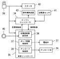
- FIG. 3 is a block diagram showing the engine controller and the vehicle body controller together with related devices in the present embodiment.
- FIG. 4 is a flowchart showing the control processing contents of the vehicle body controller at the time of engine start in the embodiment.
- FIG. 5 is a flowchart showing the control processing contents of the vehicle body controller during engine driving in the present embodiment.
- the control system includes an engine controller 34 and a vehicle body controller 35.
- the vehicle body controller 35 has, as functional configurations, a target speed setting unit 36 that sets a target speed of the engine 14 and a pump capacity control unit that controls the electromagnetic valve 27 of the regulator device 20 to control the capacity of the hydraulic pump 16. 37 and an unload control unit 38 for controlling the unload valve 24.
- the controllers 34 and 35 have an arithmetic control unit (for example, CPU) that executes arithmetic processing and control processing based on a program, and a storage unit (for example, ROM, RAM) that stores the results of the program and arithmetic processing. It is.
- a key switch 39 and a dial 40 are provided in the cab 12 described above.
- the dial 40 selects the rotational speed of the engine 14 within a rotational speed range (for example, 2000 to 800 rpm) for obtaining the discharge pressure of the hydraulic pump 16 that can be driven by the hydraulic actuator described above.
- the target rotational speed setting unit 36 of the vehicle body controller 35 sets the target rotational speed N1 of the engine 14 based on the rotational speed selected by the dial 40, and outputs the set target rotational speed N1 to the engine controller 34.
- a rotation speed sensor 41 is attached to the engine 14 (see FIG. 2 described above). The rotation speed sensor 41 detects the actual rotation speed of the engine 14 and outputs it to the engine controller 34 and the vehicle body controller 35.
- the minimum rotation speed (for example, 800 rpm) required to obtain the discharge pressure of the hydraulic pump 16 that can be driven by the hydraulic actuator is referred to as an idle rotation speed N2.
- the minimum rotational speed (for example, 200 rpm) required to obtain the discharge pressure of the pilot pump 17 that can be driven by the regulator device 20 is referred to as cranking rotational speed N4.
- the vehicle body controller 35 stores the idle speed N2 and also stores a low speed speed N3 (for example, 400 rpm) set in advance so as to be smaller than the idle speed N2 and larger than the cranking speed N4.
- the key switch 39 can be operated to the OFF position, the ON position, and the START position.
- the key switch 39 is operated from the OFF position to the ON position, the power sources of the engine controller 34 and the vehicle body controller 35 are turned on.
- the starter 42 is driven to start the engine 14 and a start signal of the key switch 39 is output to the engine controller 34 and the vehicle body controller 35. Note that the key switch 39 automatically returns from the START position to the ON position.
- the engine controller 34 controls the fuel injection device 43 of the engine 14 so as to increase the rotational speed of the engine 14. Thereafter, the fuel injection device 43 of the engine 14 is controlled so that the actual rotational speed of the engine 14 detected by the rotational speed sensor 41 is the same as the target rotational speed.
- Step S140 it is determined whether the actual rotational speed of the engine 14 detected by the rotational speed sensor 41 has reached the idle rotational speed N2 (step S150), and if the actual rotational speed of the engine 14 has reached the idle rotational speed N2, The engine flag F is rewritten to 1 (engine drive state) (step S160).
- step S220 a drive signal is output to the solenoid part of the electromagnetic valve 27 of the regulator device 20, and the electromagnetic valve 27 is connected to the pressure receiving part 33 of the tilt control valve 26 and the tank. Control is made to the switching position for communication (step S230). As a result, the capacity of the hydraulic pump 16 is varied to the minimum capacity. Thereafter, when the actual rotational speed of the engine 14 becomes zero, the output of the drive signal to the solenoid portion of the solenoid valve 27 is stopped (step S240).
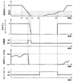
- FIG. 6 is a time chart for explaining the operation of the present embodiment.
- the actual rotational speed of the engine 14 the discharge pressure of the pilot pump 17, and The change with time of the capacity of the hydraulic pump 16 is shown.
- the rotational speed of the engine 14 decreases.
- the pump capacity control unit 37 of the vehicle body controller 35 drives the electromagnetic valve 27 of the regulator device 20 until the actual rotational speed of the engine 14 reaches zero after the low rotational speed N3 (time t2 to t3). Then, the pressure receiving portion 33 of the tilt control valve 26 and the tank are communicated.
- the capacity of the hydraulic pump 16 is varied to the minimum capacity qmin. Therefore, even when the engine 14 stops against the driver's intention, the capacity of the hydraulic pump 16 can be varied to the minimum capacity qmin. Therefore, when the engine 14 is started, the capacity of the hydraulic pump 16 does not reach the maximum capacity qmax, for example, and the load on the hydraulic pump 16 can be reduced.
- the unload control unit 38 of the vehicle body controller 35 is The unload valve 24 is driven to connect the discharge side of the pilot pump 17 and the tank. Thereby, the load of the pilot pump 17 can be reduced. At this time, since it is not necessary to drive the regulator device 20, there is no problem even if the discharge pressure of the pilot pump 17 is not sufficiently obtained.
- the pump capacity control unit 37 of the vehicle body controller 35 adjusts the regulator until the actual rotational speed of the engine 14 detected by the rotational speed sensor 41 becomes zero after the low rotational speed N3.
- a preset rotational speed for example, 100 rpm
- the electromagnetic valve 27 of the regulator device 20 may be driven. In this case, the same effect as described above can be obtained.
- the unload control unit 38 of the vehicle body controller 35 unloads the engine 14 when the engine speed detected by the engine speed sensor 41 is less than the low speed engine speed N3.
- the case where the load valve 24 is controlled to the open position and the unload valve 24 is switched to the closed position when the rotational speed of the engine 14 detected by the rotational speed sensor 41 is equal to or higher than the low speed rotational speed N3 has been described as an example.
- the present invention is not limited to this, and modifications can be made without departing from the spirit and technical idea of the present invention.
- the unload control unit 38 of the vehicle body controller 35 controls the unload valve 24 to the open position when the engine 14 is activated and the engine speed detected by the engine speed sensor 41 is less than the idle engine speed N2. Then, when the rotational speed of the engine 14 detected by the rotational speed sensor 41 becomes equal to or higher than the idle rotational speed N2, the unload valve 24 may be switched to the closed position. In this case, the same effect as described above can be obtained.
- the unload control unit 38 of the vehicle body controller 35 inputs a start signal of the key switch 39 when the engine 14 is started, and is set for a predetermined time (specifically, for example, the rotational speed of the engine 14 is low).
- the unload valve 24 is controlled to the open position until the time required to increase to the rotational speed N3 or the idle rotational speed N2 has elapsed, and after the predetermined time has elapsed, the unload valve 24 is switched to the closed position. May be. In this case, the same effect as described above can be obtained.
- the maximum operating pilot pressure is introduced into the pressure receiving portion 33 of the tilt control valve 26 of the regulator device 20, and the displacement of the hydraulic pump 16 is varied according to the maximum operating pilot pressure (positive control).
- a throttle is provided at the most downstream portion of the center bypass line passing through the plurality of directional control valves, and the upstream pressure (control pressure) of the throttle is introduced into the pressure receiving portion 33 of the tilt control valve 26 of the regulator device 20, Control (negative control) may be performed to vary the capacity of the hydraulic pump 16 in accordance with the upstream pressure of the throttle. In this case, the same effect as described above can be obtained.
- the regulator device 20 has been described by taking as an example the case of the tilt cylinder 25, the hydraulic pilot type tilt control valve 26, and the electromagnetic valve 27.
- the present invention is not limited to this. Modifications can be made without departing from the spirit and technical idea of the invention. That is, from the viewpoint of the subject of the present invention, the regulator device 20 may be any device that can change the capacity of the hydraulic pump 16 using the discharge pressure of the pilot pump 17. You may comprise a rotation control valve. In this case, the same effect as described above can be obtained.
Landscapes
- Engineering & Computer Science (AREA)
- General Engineering & Computer Science (AREA)
- Mining & Mineral Resources (AREA)
- Civil Engineering (AREA)
- Structural Engineering (AREA)
- Physics & Mathematics (AREA)
- Fluid Mechanics (AREA)
- Mechanical Engineering (AREA)
- Chemical & Material Sciences (AREA)
- Combustion & Propulsion (AREA)
- Fluid-Pressure Circuits (AREA)
- Operation Control Of Excavators (AREA)
Abstract
Description
9 ブームシリンダ
10 アームシリンダ
11 バケットシリンダ
14 エンジン
15 右側の作業用操作部材
16 油圧ポンプ
17 パイロットポンプ
18 ブーム用方向切換弁
20 レギュレータ装置
24 アンロード弁
25 傾転シリンダ
26 傾転制御弁
27 電磁弁
35 車体コントローラ
37 ポンプ容量制御部
38 アンロード制御部
39 キースイッチ
41 回転数センサ
Claims (4)
- エンジンと、
前記エンジンの回転数を検出する回転数センサと、
前記エンジンによって駆動される可変容量型の油圧ポンプと、
油圧アクチュエータと、
操作部材の操作に応じて前記油圧ポンプから前記油圧アクチュエータへの圧油の流れを制御する方向切換弁と、
前記エンジンによって駆動される固定容量型のパイロットポンプと、
前記パイロットポンプの吐出圧を用いて前記油圧ポンプの容量を可変させるレギュレータ装置と、
前記パイロットポンプの吐出側とタンクを接続する管路に設けられ、閉位置と開位置に切換可能なアンロード弁と、
前記レギュレータ装置を制御して前記油圧ポンプの容量を制御するポンプ容量制御部、及び前記エンジンの始動時に前記アンロード弁を開位置に制御するアンロード制御部を有する制御装置とを備え、
前記ポンプ容量制御部は、
前記油圧アクチュエータの駆動が可能な前記油圧ポンプの吐出圧を得るために最低限必要な前記エンジンのアイドル回転数より小さく、かつ前記レギュレータ装置の駆動が可能な前記パイロットポンプの吐出圧を得るために最低限必要な前記エンジンのクランキング回転数より大きくなるように予め設定された前記エンジンの低速回転数を記憶し、
前記エンジンの駆動中、前記回転数センサで検出された前記エンジンの回転数が前記低速回転数以下となるときに、前記レギュレータ装置を制御して前記油圧ポンプの容量を最小容量に可変させることを特徴とする建設機械。 - 請求項1記載の建設機械において、
前記レギュレータ装置は、
前記油圧ポンプの斜板の傾転角を可変させる傾転シリンダと、
前記傾転シリンダの油室と前記パイロットポンプの吐出側を連通する切換位置と、前記傾転シリンダの油室と前記タンクを連通する切換位置に切換可能な油圧パイロット式の傾転制御弁と、
前記傾転制御弁の受圧部へ制御圧を導出する管路に設けられた電磁弁とを備え、
前記ポンプ容量制御部は、
前記エンジンの駆動中、前記回転数センサで検出された前記エンジンの回転数が前記低速回転数以下となるときに、前記電磁弁を制御して前記油圧ポンプの容量を最小容量に可変させることを特徴とする建設機械。 - 請求項1記載の建設機械において、
前記アンロード制御部は、前記エンジンの始動時、前記回転数センサで検出された前記エンジンの回転数が前記低速回転数又は前記アイドル回転数未満であるときに、前記アンロード弁を開位置に制御し、前記回転数センサで検出された前記エンジンの回転数が前記低速回転数又は前記アイドル回転数以上となるときに、前記アンロード弁を閉位置に切換えることを特徴とする建設機械。 - 請求項1記載の建設機械において、
前記アンロード制御部は、前記エンジンの始動時、キースイッチの始動信号を入力してから予め設定された所定時間が経過するまで、前記アンロード弁を開位置に制御し、前記所定時間が経過してから、前記アンロード弁を閉位置に切換えることを特徴とする建設機械。
Priority Applications (6)
| Application Number | Priority Date | Filing Date | Title |
|---|---|---|---|
| PCT/JP2016/057877 WO2017154220A1 (ja) | 2016-03-11 | 2016-03-11 | 建設機械 |
| JP2017543402A JP6383114B2 (ja) | 2016-03-11 | 2016-03-11 | 建設機械 |
| KR1020177022603A KR101945436B1 (ko) | 2016-03-11 | 2016-03-11 | 건설 기계 |
| EP16891898.5A EP3428456B1 (en) | 2016-03-11 | 2016-03-11 | Construction machinery |
| CN201680010050.5A CN107407298B (zh) | 2016-03-11 | 2016-03-11 | 工程机械 |
| US15/555,685 US10329739B2 (en) | 2016-03-11 | 2016-03-11 | Construction machine |
Applications Claiming Priority (1)
| Application Number | Priority Date | Filing Date | Title |
|---|---|---|---|
| PCT/JP2016/057877 WO2017154220A1 (ja) | 2016-03-11 | 2016-03-11 | 建設機械 |
Publications (1)
| Publication Number | Publication Date |
|---|---|
| WO2017154220A1 true WO2017154220A1 (ja) | 2017-09-14 |
Family
ID=59789310
Family Applications (1)
| Application Number | Title | Priority Date | Filing Date |
|---|---|---|---|
| PCT/JP2016/057877 Ceased WO2017154220A1 (ja) | 2016-03-11 | 2016-03-11 | 建設機械 |
Country Status (6)
| Country | Link |
|---|---|
| US (1) | US10329739B2 (ja) |
| EP (1) | EP3428456B1 (ja) |
| JP (1) | JP6383114B2 (ja) |
| KR (1) | KR101945436B1 (ja) |
| CN (1) | CN107407298B (ja) |
| WO (1) | WO2017154220A1 (ja) |
Cited By (2)
| Publication number | Priority date | Publication date | Assignee | Title |
|---|---|---|---|---|
| CN107869490A (zh) * | 2017-11-21 | 2018-04-03 | 黎明液压有限公司 | 一种数字液压变速操纵阀 |
| WO2020194730A1 (ja) * | 2019-03-28 | 2020-10-01 | 日立建機株式会社 | 建設機械 |
Families Citing this family (10)
| Publication number | Priority date | Publication date | Assignee | Title |
|---|---|---|---|---|
| WO2019017159A1 (ja) * | 2017-07-18 | 2019-01-24 | 株式会社小松製作所 | パラメータ特定装置、シミュレーション装置、およびパラメータ特定方法 |
| KR20190101076A (ko) * | 2018-02-22 | 2019-08-30 | 두산인프라코어 주식회사 | 건설기계의 유압 펌프 제어 시스템 및 건설기계의 유압 펌프 제어 방법 |
| JP2020172792A (ja) * | 2019-04-11 | 2020-10-22 | 株式会社小松製作所 | 作業機械および制御方法 |
| JP7110164B2 (ja) * | 2019-09-25 | 2022-08-01 | 株式会社日立建機ティエラ | 建設機械 |
| JP7681385B2 (ja) * | 2020-07-13 | 2025-05-22 | 株式会社小松製作所 | 作業機械、作業機械の制御システム |
| JP7167224B2 (ja) * | 2021-03-19 | 2022-11-08 | 日立建機株式会社 | 作業機械 |
| GB202117524D0 (en) | 2021-12-03 | 2022-01-19 | Agco Int Gmbh | System and method for controlling a hydraulic supply system on a mobile machine |
| GB202117535D0 (en) | 2021-12-03 | 2022-01-19 | Agco Int Gmbh | System and method for controlling a hydraulic supply system on a mobile machine |
| GB202117529D0 (en) | 2021-12-03 | 2022-01-19 | Agco Int Gmbh | Mobile machine and method |
| CN116677503A (zh) * | 2023-06-12 | 2023-09-01 | 安百拓(南京)建筑矿山设备有限公司 | 工程用车及其负载控制方法 |
Citations (4)
| Publication number | Priority date | Publication date | Assignee | Title |
|---|---|---|---|---|
| JPH05125747A (ja) | 1991-11-06 | 1993-05-21 | Yanmar Diesel Engine Co Ltd | 建設機械の油圧操作機構 |
| JPH05248401A (ja) * | 1992-01-13 | 1993-09-24 | Caterpillar Inc | 油圧装置の出力を制限する方法および装置 |
| JP2008151211A (ja) | 2006-12-15 | 2008-07-03 | Hitachi Constr Mach Co Ltd | 建設機械のエンジン始動システム |
| JP2015055350A (ja) * | 2013-09-13 | 2015-03-23 | ヤンマー株式会社 | 建設機械 |
Family Cites Families (9)
| Publication number | Priority date | Publication date | Assignee | Title |
|---|---|---|---|---|
| US3884039A (en) * | 1974-05-20 | 1975-05-20 | Oilgear Co | Hydraulic pump with horsepower limiter |
| DE2449464A1 (de) * | 1974-10-19 | 1976-05-06 | Kloeckner Humboldt Deutz Ag | Hydrostatisches fahrzeuggetriebe |
| EP1533524B1 (en) * | 2002-08-26 | 2011-11-02 | Hitachi Construction Machinery Co., Ltd. | Signal processing device of construction machinery |
| JP4979638B2 (ja) * | 2008-06-11 | 2012-07-18 | カヤバ工業株式会社 | ハイブリッド建設機械の制御装置 |
| JP5015091B2 (ja) * | 2008-08-14 | 2012-08-29 | 日立建機株式会社 | 油圧作業機械のエンジンラグダウン抑制装置 |
| JP5124049B2 (ja) * | 2010-02-03 | 2013-01-23 | 株式会社小松製作所 | エンジンの制御装置 |
| JP5603115B2 (ja) | 2010-03-19 | 2014-10-08 | ヤンマー株式会社 | 作業車両の油圧回路 |
| KR20140035371A (ko) * | 2011-06-14 | 2014-03-21 | 히다치 겡키 가부시키 가이샤 | 건설 기계 |
| JP6279356B2 (ja) * | 2014-03-10 | 2018-02-14 | 株式会社神戸製鋼所 | 作業機械の油圧駆動装置 |
-
2016
- 2016-03-11 KR KR1020177022603A patent/KR101945436B1/ko active Active
- 2016-03-11 US US15/555,685 patent/US10329739B2/en active Active
- 2016-03-11 EP EP16891898.5A patent/EP3428456B1/en active Active
- 2016-03-11 CN CN201680010050.5A patent/CN107407298B/zh active Active
- 2016-03-11 JP JP2017543402A patent/JP6383114B2/ja active Active
- 2016-03-11 WO PCT/JP2016/057877 patent/WO2017154220A1/ja not_active Ceased
Patent Citations (4)
| Publication number | Priority date | Publication date | Assignee | Title |
|---|---|---|---|---|
| JPH05125747A (ja) | 1991-11-06 | 1993-05-21 | Yanmar Diesel Engine Co Ltd | 建設機械の油圧操作機構 |
| JPH05248401A (ja) * | 1992-01-13 | 1993-09-24 | Caterpillar Inc | 油圧装置の出力を制限する方法および装置 |
| JP2008151211A (ja) | 2006-12-15 | 2008-07-03 | Hitachi Constr Mach Co Ltd | 建設機械のエンジン始動システム |
| JP2015055350A (ja) * | 2013-09-13 | 2015-03-23 | ヤンマー株式会社 | 建設機械 |
Non-Patent Citations (1)
| Title |
|---|
| See also references of EP3428456A4 |
Cited By (4)
| Publication number | Priority date | Publication date | Assignee | Title |
|---|---|---|---|---|
| CN107869490A (zh) * | 2017-11-21 | 2018-04-03 | 黎明液压有限公司 | 一种数字液压变速操纵阀 |
| WO2020194730A1 (ja) * | 2019-03-28 | 2020-10-01 | 日立建機株式会社 | 建設機械 |
| JPWO2020194730A1 (ja) * | 2019-03-28 | 2021-09-13 | 日立建機株式会社 | 建設機械 |
| US11214941B2 (en) | 2019-03-28 | 2022-01-04 | Hitachi Construction Machinery Co., Ltd. | Construction machine |
Also Published As
| Publication number | Publication date |
|---|---|
| JP6383114B2 (ja) | 2018-08-29 |
| EP3428456B1 (en) | 2021-06-30 |
| JPWO2017154220A1 (ja) | 2018-03-15 |
| KR20170131361A (ko) | 2017-11-29 |
| US10329739B2 (en) | 2019-06-25 |
| CN107407298A (zh) | 2017-11-28 |
| CN107407298B (zh) | 2018-12-28 |
| EP3428456A4 (en) | 2020-03-25 |
| US20180106018A1 (en) | 2018-04-19 |
| EP3428456A1 (en) | 2019-01-16 |
| KR101945436B1 (ko) | 2019-02-07 |
Similar Documents
| Publication | Publication Date | Title |
|---|---|---|
| JP6383114B2 (ja) | 建設機械 | |
| JP6469844B2 (ja) | ショベルおよびショベルの駆動方法 | |
| JP5192367B2 (ja) | 作業車両および作業車両の制御方法 | |
| KR101952819B1 (ko) | 작업 기계의 유압 시스템 | |
| JP3819699B2 (ja) | 油圧走行車両 | |
| US20160376770A1 (en) | Shovel | |
| JP7071979B2 (ja) | ショベル | |
| WO2014084213A1 (ja) | 電動式油圧作業機械の油圧駆動装置 | |
| JP2008190694A (ja) | オートデセル制御機能を備えた制御装置及びその制御方法 | |
| JP3316053B2 (ja) | 油圧建設機械の原動機回転数制御装置 | |
| JP2010053969A (ja) | 建設機械 | |
| JP2008151211A (ja) | 建設機械のエンジン始動システム | |
| JP3686324B2 (ja) | 油圧走行車両 | |
| JPH07127605A (ja) | 油圧建設機械の駆動制御装置 | |
| JP6752686B2 (ja) | ショベル | |
| JP2014218889A (ja) | 作業機械 | |
| JP7039505B2 (ja) | 建設機械 | |
| JP5755865B2 (ja) | 油圧駆動装置および油圧駆動装置を備えた作業機械 | |
| JP7062445B2 (ja) | ショベル | |
| WO2017164169A1 (ja) | ショベル及びショベル用コントロールバルブ | |
| JP2017145963A (ja) | 油圧式作業車両の制御装置 | |
| JP2013044398A (ja) | 油圧駆動システム | |
| CN105889015B (zh) | 液压驱动系统 | |
| JP3308073B2 (ja) | 油圧建設機械の原動機回転数制御装置 | |
| WO2023171295A1 (ja) | 建設機械の制御装置およびこれを備えた建設機械 |
Legal Events
| Date | Code | Title | Description |
|---|---|---|---|
| ENP | Entry into the national phase |
Ref document number: 20177022603 Country of ref document: KR Kind code of ref document: A |
|
| ENP | Entry into the national phase |
Ref document number: 2017543402 Country of ref document: JP Kind code of ref document: A |
|
| WWE | Wipo information: entry into national phase |
Ref document number: 15555685 Country of ref document: US |
|
| REEP | Request for entry into the european phase |
Ref document number: 2016891898 Country of ref document: EP |
|
| NENP | Non-entry into the national phase |
Ref country code: DE |
|
| 121 | Ep: the epo has been informed by wipo that ep was designated in this application |
Ref document number: 16891898 Country of ref document: EP Kind code of ref document: A1 |