WO2017154256A1 - 電動補助車両の駆動装置、電動補助車両、及び蓄電装置 - Google Patents
電動補助車両の駆動装置、電動補助車両、及び蓄電装置 Download PDFInfo
- Publication number
- WO2017154256A1 WO2017154256A1 PCT/JP2016/080172 JP2016080172W WO2017154256A1 WO 2017154256 A1 WO2017154256 A1 WO 2017154256A1 JP 2016080172 W JP2016080172 W JP 2016080172W WO 2017154256 A1 WO2017154256 A1 WO 2017154256A1
- Authority
- WO
- WIPO (PCT)
- Prior art keywords
- temperature
- storage element
- power storage
- thermal connection
- connection switching
- Prior art date
- Legal status (The legal status is an assumption and is not a legal conclusion. Google has not performed a legal analysis and makes no representation as to the accuracy of the status listed.)
- Ceased
Links
Images








Classifications
-
- H—ELECTRICITY
- H01—ELECTRIC ELEMENTS
- H01M—PROCESSES OR MEANS, e.g. BATTERIES, FOR THE DIRECT CONVERSION OF CHEMICAL ENERGY INTO ELECTRICAL ENERGY
- H01M10/00—Secondary cells; Manufacture thereof
- H01M10/60—Heating or cooling; Temperature control
- H01M10/61—Types of temperature control
- H01M10/613—Cooling or keeping cold
-
- B—PERFORMING OPERATIONS; TRANSPORTING
- B60—VEHICLES IN GENERAL
- B60L—PROPULSION OF ELECTRICALLY-PROPELLED VEHICLES; SUPPLYING ELECTRIC POWER FOR AUXILIARY EQUIPMENT OF ELECTRICALLY-PROPELLED VEHICLES; ELECTRODYNAMIC BRAKE SYSTEMS FOR VEHICLES IN GENERAL; MAGNETIC SUSPENSION OR LEVITATION FOR VEHICLES; MONITORING OPERATING VARIABLES OF ELECTRICALLY-PROPELLED VEHICLES; ELECTRIC SAFETY DEVICES FOR ELECTRICALLY-PROPELLED VEHICLES
- B60L50/00—Electric propulsion with power supplied within the vehicle
- B60L50/50—Electric propulsion with power supplied within the vehicle using propulsion power supplied by batteries or fuel cells
- B60L50/60—Electric propulsion with power supplied within the vehicle using propulsion power supplied by batteries or fuel cells using power supplied by batteries
- B60L50/64—Constructional details of batteries specially adapted for electric vehicles
-
- B—PERFORMING OPERATIONS; TRANSPORTING
- B62—LAND VEHICLES FOR TRAVELLING OTHERWISE THAN ON RAILS
- B62M—RIDER PROPULSION OF WHEELED VEHICLES OR SLEDGES; POWERED PROPULSION OF SLEDGES OR SINGLE-TRACK CYCLES; TRANSMISSIONS SPECIALLY ADAPTED FOR SUCH VEHICLES
- B62M6/00—Rider propulsion of wheeled vehicles with additional source of power, e.g. combustion engine or electric motor
- B62M6/40—Rider propelled cycles with auxiliary electric motor
- B62M6/45—Control or actuating devices therefor
-
- H—ELECTRICITY
- H01—ELECTRIC ELEMENTS
- H01M—PROCESSES OR MEANS, e.g. BATTERIES, FOR THE DIRECT CONVERSION OF CHEMICAL ENERGY INTO ELECTRICAL ENERGY
- H01M10/00—Secondary cells; Manufacture thereof
- H01M10/42—Methods or arrangements for servicing or maintenance of secondary cells or secondary half-cells
- H01M10/44—Methods for charging or discharging
-
- H—ELECTRICITY
- H01—ELECTRIC ELEMENTS
- H01M—PROCESSES OR MEANS, e.g. BATTERIES, FOR THE DIRECT CONVERSION OF CHEMICAL ENERGY INTO ELECTRICAL ENERGY
- H01M10/00—Secondary cells; Manufacture thereof
- H01M10/42—Methods or arrangements for servicing or maintenance of secondary cells or secondary half-cells
- H01M10/48—Accumulators combined with arrangements for measuring, testing or indicating the condition of cells, e.g. the level or density of the electrolyte
- H01M10/486—Accumulators combined with arrangements for measuring, testing or indicating the condition of cells, e.g. the level or density of the electrolyte for measuring temperature
-
- H—ELECTRICITY
- H01—ELECTRIC ELEMENTS
- H01M—PROCESSES OR MEANS, e.g. BATTERIES, FOR THE DIRECT CONVERSION OF CHEMICAL ENERGY INTO ELECTRICAL ENERGY
- H01M10/00—Secondary cells; Manufacture thereof
- H01M10/60—Heating or cooling; Temperature control
- H01M10/61—Types of temperature control
- H01M10/615—Heating or keeping warm
-
- H—ELECTRICITY
- H01—ELECTRIC ELEMENTS
- H01M—PROCESSES OR MEANS, e.g. BATTERIES, FOR THE DIRECT CONVERSION OF CHEMICAL ENERGY INTO ELECTRICAL ENERGY
- H01M10/00—Secondary cells; Manufacture thereof
- H01M10/60—Heating or cooling; Temperature control
- H01M10/62—Heating or cooling; Temperature control specially adapted for specific applications
- H01M10/625—Vehicles
-
- H—ELECTRICITY
- H01—ELECTRIC ELEMENTS
- H01M—PROCESSES OR MEANS, e.g. BATTERIES, FOR THE DIRECT CONVERSION OF CHEMICAL ENERGY INTO ELECTRICAL ENERGY
- H01M10/00—Secondary cells; Manufacture thereof
- H01M10/60—Heating or cooling; Temperature control
- H01M10/63—Control systems
- H01M10/633—Control systems characterised by algorithms, flow charts, software details or the like
-
- H—ELECTRICITY
- H01—ELECTRIC ELEMENTS
- H01M—PROCESSES OR MEANS, e.g. BATTERIES, FOR THE DIRECT CONVERSION OF CHEMICAL ENERGY INTO ELECTRICAL ENERGY
- H01M10/00—Secondary cells; Manufacture thereof
- H01M10/60—Heating or cooling; Temperature control
- H01M10/66—Heat-exchange relationships between the cells and other systems, e.g. central heating systems or fuel cells
- H01M10/667—Heat-exchange relationships between the cells and other systems, e.g. central heating systems or fuel cells the system being an electronic component, e.g. a CPU, an inverter or a capacitor
-
- H—ELECTRICITY
- H02—GENERATION; CONVERSION OR DISTRIBUTION OF ELECTRIC POWER
- H02J—ELECTRIC POWER NETWORKS; CIRCUIT ARRANGEMENTS OR SYSTEMS FOR SUPPLYING OR DISTRIBUTING ELECTRIC POWER; SYSTEMS FOR STORING ELECTRIC ENERGY
- H02J7/00—Circuit arrangements for charging or discharging batteries or for supplying loads from batteries
-
- H—ELECTRICITY
- H01—ELECTRIC ELEMENTS
- H01M—PROCESSES OR MEANS, e.g. BATTERIES, FOR THE DIRECT CONVERSION OF CHEMICAL ENERGY INTO ELECTRICAL ENERGY
- H01M2220/00—Batteries for particular applications
- H01M2220/20—Batteries in motive systems, e.g. vehicle, ship, plane
-
- Y—GENERAL TAGGING OF NEW TECHNOLOGICAL DEVELOPMENTS; GENERAL TAGGING OF CROSS-SECTIONAL TECHNOLOGIES SPANNING OVER SEVERAL SECTIONS OF THE IPC; TECHNICAL SUBJECTS COVERED BY FORMER USPC CROSS-REFERENCE ART COLLECTIONS [XRACs] AND DIGESTS
- Y02—TECHNOLOGIES OR APPLICATIONS FOR MITIGATION OR ADAPTATION AGAINST CLIMATE CHANGE
- Y02E—REDUCTION OF GREENHOUSE GAS [GHG] EMISSIONS, RELATED TO ENERGY GENERATION, TRANSMISSION OR DISTRIBUTION
- Y02E60/00—Enabling technologies; Technologies with a potential or indirect contribution to GHG emissions mitigation
- Y02E60/10—Energy storage using batteries
-
- Y—GENERAL TAGGING OF NEW TECHNOLOGICAL DEVELOPMENTS; GENERAL TAGGING OF CROSS-SECTIONAL TECHNOLOGIES SPANNING OVER SEVERAL SECTIONS OF THE IPC; TECHNICAL SUBJECTS COVERED BY FORMER USPC CROSS-REFERENCE ART COLLECTIONS [XRACs] AND DIGESTS
- Y02—TECHNOLOGIES OR APPLICATIONS FOR MITIGATION OR ADAPTATION AGAINST CLIMATE CHANGE
- Y02T—CLIMATE CHANGE MITIGATION TECHNOLOGIES RELATED TO TRANSPORTATION
- Y02T10/00—Road transport of goods or passengers
- Y02T10/60—Other road transportation technologies with climate change mitigation effect
- Y02T10/70—Energy storage systems for electromobility, e.g. batteries
Definitions
- the present invention relates to a drive device for a motor-assisted vehicle, a motor-assisted vehicle, and a power storage device.
- Patent Document 1 describes a battery temperature control device configured for the purpose of preventing a reduction in battery output, capacity, life, and the like by controlling the battery temperature to be always the optimum operating temperature.
- the battery temperature control device supplies a motor for running the vehicle, supplies power to the motor, a battery having an optimum operating temperature near room temperature, a heat generating member that generates heat when the vehicle starts, and dissipates heat generated by the battery to the outside of the vehicle.
- a radiator a heater core that dissipates heat generated by the battery into the vehicle, a battery temperature detection sensor that detects the temperature of the battery, and heat generated by the heating member when the battery temperature is lower than the appropriate range.
- Patent Document 2 describes a battery control device configured for the purpose of preventing a reduction in battery input / output power due to a temperature drop.
- the battery control device includes battery temperature detection means for detecting the temperature of the battery, charge state determination means for determining the charge state of the battery, and battery control means for controlling charge / discharge of the battery.
- the temperature of the battery detected by the temperature detecting means is not more than a predetermined value and the state of charge of the battery determined by the charge state determining means is not less than a preset threshold value, the battery is within a predetermined area not less than the threshold value.
- the charge state of the battery is less than the threshold value, the charge / discharge of the battery is repeated within a predetermined region less than the threshold value.
- an electrically assisted vehicle equipped with a mechanism for assisting human power by driving a motor with electric power stored in an electric storage element
- a technique for charging the electric storage element with electric power generated during the regenerative operation of the motor to obtain a braking force by regeneration is known.
- storage elements such as lithium ion secondary batteries used in battery-assisted vehicles have low charge / discharge performance at low temperatures such as winter and high temperatures such as summer. Inability to do so is an issue. For example, if the temperature of the electricity storage element becomes low in winter, etc., the charging performance deteriorates, so that the braking force due to regeneration cannot be obtained sufficiently, for example, the passenger may feel discomfort or fear while traveling downhill Yes, it can be a factor that reduces product power. Also, in summer, etc., the temperature rise due to discharge may be added and the storage element may become hot. For battery protection, the battery controller limits charging / discharging of the battery, so driving force and braking force due to regeneration May be limited.
- the present invention has been made in view of these problems, and is a drive device for a battery-assisted vehicle capable of stably obtaining a driving force and a braking force due to regeneration by maintaining the power storage element in an appropriate temperature range,
- An object is to provide a battery-assisted vehicle and a power storage device.
- One of the present invention is a drive device for a battery-assisted vehicle, which drives a motor provided in the battery-assisted vehicle by power stored in a power storage element and generates power during a regenerative operation of the motor.
- a motor drive control device that charges the power storage element, a power storage element temperature acquisition unit that acquires a power storage element temperature that is a temperature of the power storage element, and heat that thermally connects or disconnects the power storage element and the motor drive control device.
- a connection switching device and a thermal connection switching control unit for controlling the thermal connection switching device so that the power storage device is thermally connected to the motor drive control device when the temperature of the power storage device is less than a first predetermined value And comprising.
- the power storage element when the temperature of the power storage element is lower than the first predetermined value, the power storage element is heated using the heat of the motor drive control device. Therefore, it is possible to stably obtain a driving force and a braking force due to regeneration by maintaining the power storage element in an appropriate temperature range.
- thermal connection switching control unit is configured to drive the power storage element and the motor when the power storage element temperature is equal to or higher than the first predetermined value.
- the thermal connection switching device is controlled so as to thermally disconnect the control device.
- the storage element and the motor drive control device are thermally separated from each other. Can be prevented.
- Another aspect of the present invention is the drive device for the battery-assisted vehicle, wherein the thermal connection switching control unit is configured such that the battery element and the battery-assisted battery are operated when the temperature of the battery element is equal to or higher than the first predetermined value.
- the thermal connection switching device is controlled to thermally connect a predetermined part of the vehicle.
- the storage element temperature is equal to or higher than the first predetermined value
- the storage element and a predetermined part (frame, seat tube, hanger pipe, chain stay, front pipe, etc.) of the battery-assisted vehicle are thermally connected. Heat can be released to a predetermined portion, and the charge and discharge performance can be prevented from being lowered due to the high temperature of the power storage element.
- the thermal connection switching control unit has a temperature equal to or higher than a temperature obtained by adding a predetermined hysteresis width value to the first predetermined value.
- the thermal connection switching device is controlled so as to thermally separate the power storage element and the motor drive control device.
- the drive device for the electric auxiliary vehicle further comprising a motor drive control device temperature acquisition unit that acquires a motor drive control device temperature that is a temperature of the motor drive control device, and the heat
- the connection switching control unit is configured to switch the power storage element and the motor drive control device when the power storage element temperature is less than the first predetermined value and the motor drive control device temperature is equal to or lower than a second predetermined value.
- the thermal connection switching device is controlled so as to be thermally disconnected.
- the power storage device and the motor drive control device are thermally separated, so that the motor drive is performed when the motor drive control device temperature is low as in winter.
- the control device thermally it is possible to prevent the charge and discharge performance from being lowered due to the low temperature of the storage element.
- the drive device for the electric auxiliary vehicle further comprising a predetermined part temperature acquisition unit that acquires a predetermined part temperature that is a temperature of the predetermined part
- the thermal connection switching control unit includes: When the storage element temperature is equal to or higher than the first predetermined value and the predetermined part temperature is equal to or higher than a third predetermined value, the thermal connection switching is performed so as to thermally separate the storage element from the predetermined part. Control the device.
- the power storage element when the predetermined part temperature is high (the third predetermined value or more), the power storage element is thermally separated from the predetermined part. Therefore, the storage element can be used when the temperature of the predetermined part is high as in summer. Is thermally connected to a predetermined portion, so that it is possible to prevent the storage element from becoming hot and the charge / discharge performance from deteriorating.
- the drive device for the electric auxiliary vehicle further comprising a predetermined part temperature acquisition unit that acquires a predetermined part temperature that is a temperature of the predetermined part
- the thermal connection switching control unit includes: When the storage element temperature is equal to or higher than a temperature obtained by adding a predetermined hysteresis width value to the first predetermined value, and the predetermined part temperature is equal to or higher than a third predetermined value, the storage element and the predetermined part are The thermal connection switching device is controlled so as to be thermally disconnected.
- Another aspect of the present invention is the drive device for the battery-assisted vehicle, wherein the power storage element has a regenerative chargeable temperature range that is a temperature range in which the regenerative control unit can be charged. Is set within the regenerative chargeable temperature range.
- Another one of the present invention is a drive device for the electric auxiliary vehicle, which includes the thermal connection switching device.
- Another aspect of the present invention is a battery-assisted vehicle equipped with the above drive device.
- Another aspect of the present invention is a power storage device including the power storage element and the thermal connection switching device.
- FIG. 1 is an external view of an electrically assisted bicycle 1.
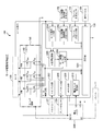
- FIG. It is a figure which shows the structure (block diagram) of the motor drive control apparatus. It is a figure which shows the example of mounting to the electrically assisted bicycle 1 of the motor control circuit. It is the perspective view which looked at the inside of substrate case 131 from the slanting upper part.
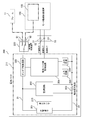
- 3 is a diagram showing a configuration (block diagram) of a battery pack 200.
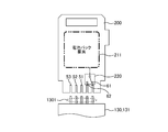
- FIG. It is a figure which shows the structural example of the battery pack 200 and the connector base 130.
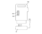
- FIG. It is an external view which shows the state in which the charger 30 used for charge of the battery pack 200 and the battery pack 200 were connected.
- thermal connection switching apparatus 220 by thermal connection switching control. It is a figure which shows one state of the thermal connection switching apparatus 220 by thermal connection switching control. It is a figure which shows one state of the thermal connection switching apparatus 220 by thermal connection switching control. It is a figure which shows one state of the thermal connection switching apparatus 220 by thermal connection switching control. It is a figure explaining the specific example (control method (1)) of thermal connection switching control. It is a flowchart explaining thermal connection switching process S1200.
- an electrically assisted bicycle will be described as an example of an electrically assisted vehicle.
- the present invention is not limited to an electrically assisted bicycle, and other types of assistance such as an electrically assisted wheelchair, for example. It can also be applied to powered vehicles.
- common or similar components are given the same or similar reference numerals.
- Fig. 1 shows the external appearance of the electrically assisted bicycle 1.
- the electrically assisted bicycle 1 includes a frame 11, a front pipe 12, a saddle 13, a crank 14, a pedal 15, a chain 16, a handle 17, a front wheel 18, a rear wheel 19, a storage element 201 (
- the configuration includes a battery pack 200 having a built-in battery, a motor drive control device 100, a motor 105 (electric motor), and the like.
- Battery pack 200 is an example of a power storage device.
- a handle 17 is attached to one end of the frame 11 via a front pipe 12.
- a saddle 13 is attached to the other end of the frame 11.
- the handle 17 is provided with a brake lever 20, a brake sensor 104 that detects the operation of the brake lever 20, and an operation panel 106.
- the frame 11 is provided with a crank 14 that rotates with the crankshaft 108 as a rotation axis.
- the crank 14 rotates when the pedaling force of the passenger acts through the pedal 15.
- the crank 14 is provided with a torque sensor 107 that detects torque generated in the crank 14 when the passenger depresses the pedal 15.
- the frame 11 includes a frame temperature sensor 103 that measures the temperature of the frame 11.
- the temperature sensor may be used as the frame temperature sensor 103.
- the temperature sensor of the torque sensor 107 is used as the frame temperature sensor 103.
- a front wheel 18 is provided at the lower end of the front pipe 12.
- a motor 105 is built in a portion that becomes a hub of the front wheel 18.
- the front wheel 18 is rotationally driven by a motor 105.
- the motor 105 is a brushless DC motor, but the motor 105 may be another type of motor.
- the rear wheel 19 disposed on the opposite side of the front wheel 18 with respect to the crank 14 is rotationally driven via a chain 16 installed between the crank 14 and the rear wheel 19.
- the crank 14, the chain 16, and the rear wheel 19 constitute a human power drive mechanism.
- the human power drive mechanism may include a speed change mechanism.
- the chain 16 may be a transmission belt.
- a battery pack 200 is detachably disposed below the saddle 13 between the frame 11 and the rear wheel 19 of the electrically assisted bicycle 1. Between the battery pack 200 and the saddle 13, a motor drive control device 100, which is an example of a drive device, is provided.
- the motor drive control device 100 mainly includes a drive control unit that controls driving (assist operation) of the motor 105 by electric power supplied from the battery pack 200, and the battery pack 200 (storage element) by electric power generated during the regenerative operation of the motor 105. 201) functions as a regeneration control unit for charging (hereinafter also referred to as regenerative charging).
- FIG. 2 shows a configuration (block diagram) of the motor drive control device 100.
- the motor drive control device 100 includes a switch circuit 140, a motor control circuit 120, and a heat conductor 150.
- the switch circuit 140 functions as an inverter that supplies a three-phase AC current based on the DC current from the battery pack 200 to the windings of the motor 105 when the motor 105 is driven (at the time of assist operation). It functions as a converter that supplies the DC voltage obtained by converting the electromotive force 105 to the battery pack 200.
- the switch circuit 140 includes six switch elements 1411 (a high side that performs switching for the U phase of the motor 105) that form a bridge circuit corresponding to the U phase, V phase, and W phase of the motor 105.
- Each switch element 1411 is configured using, for example, an FET (Field Effect Transistor).
- the switch circuit 140 constitutes a part of a complementary switching amplifier.
- Each switch element 1411 is turned on / off by, for example, PWM (Pulse Width Modulation) control.
- the heat conductor 150 is configured using a material having a high thermal conductivity such as a metal, for example.
- the heat conductor 150 is provided for the purpose of exchanging heat between the motor drive control device 100 and the battery pack 200.
- the heat conductor 150 is provided, for example, in the vicinity of the above-described switch element 1411 or in the vicinity of a portion of the motor drive control device 100 that easily generates heat, such as an element of the motor control circuit 120 that easily generates heat.
- the heat conductor 150 is thermally connected to an external connection terminal 62 (described later) of the battery pack 200 when the battery pack 200 is attached to the electric assist bicycle 1.
- that two members are thermally connected means that they are connected in a state where heat conduction can be efficiently performed between them.
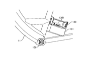
- FIG. 3 shows an example of mounting the motor control circuit 120 on the electrically assisted bicycle 1.
- a connector base 130 serving as a base on which the battery pack 200 is mounted is provided in the vicinity of the portion of the frame 11 where the crankshaft 108 is provided.
- a hollow substantially rectangular parallelepiped substrate case 131 is disposed below the connector base 130. Main elements of the motor control circuit 120 are accommodated in the substrate case 131.
- the connector base 130 is provided with a plurality of terminals 1301 corresponding to each of five external connection terminals 51 to 53, 61, 62 described later provided in the battery pack 200.
- the terminal connected to the external connection terminal 61 of the battery pack 200 is thermally connected to the frame 11.
- the said terminal is thermally applied to predetermined parts (seat tube (not shown), hanger pipe (not shown), chain stay (not shown), front pipe 12 etc.) other than the frame 11, for example. It may be connected.
- FIG. 4 is a perspective view of the inside of the substrate case 131 as viewed from obliquely above the substrate case 131.
- the circuit board 1311 of the motor control circuit 120 is accommodated in the substrate case 131.
- switch elements 1411 constituting the switch circuit 140 are disposed with their respective heat radiation surfaces in contact with the side surfaces.
- the heat conductor 150 is provided so that at least a part thereof passes in the vicinity of the switch element 1411.
- the motor control circuit 120 controls the motor 105 according to the output signals of the brake sensor 104 and the torque sensor 107.
- the motor control circuit 120 includes a calculation unit 1201, a motor drive control device temperature input unit 1202, a frame temperature input unit 1203, a motor speed input unit 1204, a variable delay circuit 1205, a motor drive timing generation unit 1206, A torque input unit 1207, a brake input unit 1208, an AD input unit 1209, and a battery pack communication unit 1210 are provided.
- the calculation unit 1201 includes a central processing unit (CPU (Central Processing Unit), MPU (Micro Processing Unit), etc.), a storage device (ROM (Read Only Memory), RAM (Random Access Memory), NVRAM (Non-Volatile RAM). Etc.).
- the arithmetic unit 1201 performs control (drive control and regenerative control) of the motor 105 based on various input signals.
- the arithmetic unit 1201 performs thermal connection switching control, which will be described later, based on various input signals. Note that the function of the calculation unit 1201 is realized by, for example, the central processing unit of the calculation unit 1201 reading and executing a program stored in the storage device of the calculation unit 1201.
- the motor speed input unit 1204 detects the rotation speed of the motor 105 based on a Hall element signal (Hall signal) for detecting the magnetic pole position of the rotor of the motor 105 and outputs the detected rotation speed to the calculation unit 1201. .
- Hall signal Hall element signal
- the torque input unit 1207 receives a torque signal indicating the torque acting on the crank 14 from the torque sensor 107, digitizes the received torque signal, and outputs the digitized torque signal to the calculation unit 1201.
- the computing unit 1201 uses the received torque signal for determining whether or not a regenerative operation is possible, for example.
- the brake input unit 1208 digitizes a signal indicating the presence or absence of the brake from the brake sensor 104 and outputs the digitized signal to the calculation unit 1201. For example, the calculation unit 1201 starts the regenerative operation when the braking signal is input.
- the AD input unit 1209 measures the output voltage of the battery pack 200 and outputs the measured voltage signal to the calculation unit 1201.
- the arithmetic unit 1201 performs charge / discharge control (overcharge suppression control, overdischarge suppression control, etc.) of the battery pack 200 according to the value of the input voltage signal.
- the operation panel 106 provides a user interface for the user to set and monitor the state of the electrically assisted bicycle 1.
- the operation panel 106 is, for example, a mode in which the user operates in an operation mode (strong assist mode: mode in which assistance by driving force is prioritized, middle assist mode: mode in which assistance by driving force is balanced with regenerative operation, and weak assist mode: regenerative operation.
- Input mode operation buttons, etc.
- vehicle speed remaining amount of battery pack 200, whether or not the headlamp is lit, operation mode, etc.
- Display unit LCD (Liquid Crystal Display), LED (Light Emitting Diode), etc.) and the like.
- the calculation unit 1201 receives an operation input performed by the user on the operation panel 106. In addition, the calculation unit 1201 displays information such as whether or not the headlamp is turned on and the total amount of electric energy (remaining battery amount) stored in the battery pack 200 on the operation panel 106.
- the battery pack communication unit 1210 includes a communication interface such as an SM bus (System Management Bus) or I2C (Inter-Integrated Circuit), and communicates with the battery pack 200 via the communication interface.
- the battery pack communication unit 1210 acquires information on the battery pack 200 (including, for example, the temperature of the power storage element 201 built in the battery pack 200 (hereinafter also referred to as battery temperature (power storage element temperature)).
- the result is output to the calculation unit 1201.
- the battery temperature is, for example, the minimum value or the maximum value of each temperature of the plurality of power storage elements 201.
- the motor drive control device temperature input unit 1202 When receiving a signal from the motor drive control device temperature sensor 102 (hereinafter also referred to as a motor drive control device temperature), the motor drive control device temperature input unit 1202 outputs the received motor drive control device temperature to the calculation unit 1201. .
- the frame temperature input unit 1203 When the frame temperature input unit 1203 receives a signal from the frame temperature sensor 103 (hereinafter also referred to as a frame temperature), the frame temperature input unit 1203 outputs the received frame temperature to the calculation unit 1201.
- the calculation unit 1201 receives output signals from the operation panel 106, the motor speed input unit 1204, the torque input unit 1207, the brake input unit 1208, and the AD input unit 1209, performs predetermined calculations, and performs a motor drive timing generation unit 1206 and the like.
- An instruction signal is output to the variable delay circuit 1205 to control driving (assist operation) of the motor 105 and regenerative operation of the motor 105.
- the computing unit 1201 determines, for example, the operation of the brake lever 20 grasped from the input signal from the brake sensor 104, and controls the regenerative operation when there is a brake operation.
- a braking force hereinafter also referred to as a regeneration amount
- the arithmetic unit 1201 controls the regeneration amount according to the battery temperature.
- the variable delay circuit 1205 adjusts the phase of the Hall signal received from the Hall element of the motor 105 based on the instruction signal (advance angle value, etc.) received from the arithmetic unit 1201, and uses the adjusted Hall signal as the motor drive timing generation unit. 1206 is output.
- the calculation unit 1201 outputs, for example, a PWM code corresponding to a duty ratio of PWM obtained as a calculation result to the motor drive timing generation unit 1206.
- the motor drive timing generation unit 1206 generates a switching signal based on the adjusted Hall signal from the variable delay circuit 1205 and the PWM code from the calculation unit 1201, and the generated switching signal is sent to the switch element 1411 of the switch circuit 140. Output.
- the basic operation of the motor drive is also described in, for example, the pamphlet of International Publication No. 2012/086459.
- FIG. 5 shows a configuration (block diagram) of the battery pack 200.
- the battery pack 200 includes a power storage element 201, a monitoring circuit 202, a current detection resistor 203, a battery pack side control circuit 204, an on / off control circuit 205, an input circuit 208, an output circuit 209, a temperature sensor 210, a heat sensor.
- a conductor 211, a thermal connection switching device 220, and external connection terminals 51 to 53, 61, 62 are provided.
- the storage element 201 is, for example, a lithium ion secondary battery, but may be a lithium ion polymer secondary battery, a nickel metal hydride battery, or the like.
- the battery pack 200 includes, for example, a plurality of power storage elements 201 connected in series or in parallel to obtain a necessary output voltage.
- the temperature sensor 210 is configured using, for example, a thermistor, and measures the temperature of the power storage element 201 (or the vicinity of the power storage element 201).
- the monitoring circuit 202 includes a voltage across the storage element 201, an output voltage of the battery pack 200 (voltage between the positive line 21 and the negative line 22), an output current or a charging current (current detection resistor 203) of the battery pack 200. Current detected), the temperature input from the temperature sensor 210, and the like, and the acquired value is output to the battery pack control circuit 204.
- the battery pack side control circuit 204 includes a central processing unit (CPU, MPU, etc.) and a storage device (ROM, RAM, NVRAM, etc.).
- the battery pack side control circuit 204 controls on / off of a protection element described later based on a signal input from the monitoring circuit 202, the input circuit 208, or the communication terminal 52.
- the on / off control circuit 205 includes a protection element (a discharge control element, a charge control element, etc.) provided on the positive line 21 of the storage element 201, and the protection element is turned on according to a control signal input from the battery pack side control circuit 204. Turn on and off.
- a protection element a discharge control element, a charge control element, etc.
- the input circuit 208 is an interface that receives a user's operation input, and includes, for example, an operation button or a push switch.
- the output circuit 209 is a user interface that provides information to the user, and includes, for example, one or more light emitting diodes (LEDs).
- LEDs light emitting diodes
- the heat conductor 211 is configured by using a material having high thermal conductivity such as metal.
- the heat conductor 211 is arranged so that at least a part thereof can efficiently exchange heat with the power storage element 201.
- the heat conductor 211 acts to supply heat to the power storage element 201 to raise the temperature of the power storage element 201.
- the heat conductor 211 acts to absorb heat from the power storage element 201 and lower the temperature of the power storage element 201.
- a part of the heat conductor 211 is thermally connected to the thermal connection switching device 220.
- the thermal connection switching device 220 switches the thermal connection destination of the thermal conductor 211 to any of the frame 11, the motor drive control device 100, and open (no connection).
- the thermal connection switching device 220 is configured using, for example, one or more electric relays.
- an electrical relay apparatus it is preferable to use what uses the metal with high heat conductivity as a contact.
- an electrical relay device one that can efficiently and thermally connect two members when turned on, and that can reliably release the thermal connection between the two members when turned off is used. Is preferred.
- One of the two terminals that are the switching destination of the terminal to which the thermal conductor 211 is connected of the thermal connection switching device 220 is thermally connected to the external connection terminal 61 of the battery pack 200, and the other one. Is thermally connected to the external connection terminal 62 of the battery pack 200.
- FIG. 6 shows a configuration example of the battery pack 200 and the connector base 130.
- a thermal connection switching device 220 is provided in the vicinity of the external connection terminals 51 to 53, 61, 62 of the battery pack 200.
- the external connection terminals 51 to 53 of the battery pack 200 are electrically connected to the circuit board 1311 of the motor drive control device 100 through the corresponding terminals of the terminal group 1301 of the connector base 130.
- the external connection terminals 61 of the battery pack 200 are thermally connected to the frame 11 via corresponding terminals of the terminal group 1301.
- the external connection terminal 62 of the battery pack 200 is thermally connected to the heat conductor 150 of the motor drive control device 100 via a corresponding terminal of the terminal group 1301.
- FIG. 7 is an external view showing a state where the charger 30 used for charging the battery pack 200 and the battery pack 200 are connected.
- the charger 30 includes a power supply circuit that generates a DC charging current based on AC from a commercial power supply, a current detection resistor, a cutoff switch, and the like.
- the charger 30 performs charge control by constant current constant voltage control (CVCC (Constant Voltage Constant Constant Current power supply)) while monitoring the charge voltage and charge current of the battery pack 200.
- CVCC Constant Voltage Constant Constant Current power supply
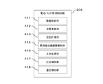
- FIG. 8 shows functions provided in the battery pack side control circuit 204 shown in FIG. 5 and data stored in the battery pack side control circuit 204.
- the battery pack side control circuit 204 includes a monitoring control unit 411, a charge control unit 412, a temperature measurement unit 413, a thermal connection switching device control unit 414, an input processing unit 416, an output control unit 417, and a communication.
- Each function of the control unit 418 is provided. These functions are performed, for example, when the central processing unit of the battery pack side control circuit 204 reads and executes a program stored in the storage device of the battery pack side control circuit 204, or for example, the battery pack side control circuit 204. This is realized by the hardware included in.
- the monitoring control unit 411 controls on / off of the protection element based on the measurement value input from the monitoring circuit 202.
- the monitoring control unit 411 monitors, for example, an abnormality in the temperature of the power storage element 201 or the protection element, overcharge or overdischarge of the power storage element 201, an overcurrent at the time of charge or an overcurrent at the time of discharge, and detects an abnormality when detecting the abnormality. Turn off.
- the charging control unit 412 performs charging control of the storage element 201 (control of charging current, control of cell balance between the storage elements 201, etc.) when charging by the charger 30 or regenerative charging is performed.
- the temperature measurement unit 413 outputs the measurement value of the temperature sensor 210 to the communication control unit 418.
- the thermal connection switching device control unit 414 receives an instruction (hereinafter also referred to as a switching instruction) sent from the calculation unit 1201 of the motor drive control device 100 via the communication control unit 418, and responds to the received switching instruction. Then, the thermal connection switching device 220 is controlled to switch the connection destination of the heat conductor 211.
- a switching instruction an instruction sent from the calculation unit 1201 of the motor drive control device 100 via the communication control unit 418
- the communication control unit 418 communicates with the motor drive control device 100 via the communication terminal 52.
- the communication control unit 418 notifies the motor drive control device 100 of the temperature measured by the temperature measurement unit 413.
- the input processing unit 416 receives an operation performed by the user on the input circuit 208 and inputs a signal corresponding to the received operation to the battery pack side control circuit 204.
- the output control unit 417 outputs information to the output circuit 209.
- FIG. 9 shows an example of a regeneration amount limitation method according to the battery temperature, which is performed by the calculation unit 1201 of the motor control circuit 120.
- the calculation unit 1201 limits the regeneration amount according to the battery temperature.
- the calculation unit 1201 stores a low temperature side stop temperature, a low temperature side limit temperature, a high temperature side start temperature, and a high temperature side stop temperature. These values are determined according to the specifications of the power storage element 201 of the battery pack 200, for example. For example, when the battery temperature ⁇ the low temperature side stop temperature, the calculation unit 1201 sets the regeneration amount to 0% (stops the regeneration operation).
- the calculation unit 1201 increases the regeneration amount ( ⁇ 100%) as the battery temperature increases. Further, for example, the calculation unit 1201 maintains the regeneration amount at 100% when the low temperature side restriction start temperature ⁇ battery temperature ⁇ the high temperature side restriction start temperature. Further, for example, the calculation unit 1201 reduces the regenerative amount as the battery temperature increases ( ⁇ 100%) when the high temperature side restriction start temperature ⁇ the battery temperature ⁇ the high temperature side stop temperature. For example, when the high temperature side stop temperature ⁇ the battery temperature, the calculation unit 1201 sets the regeneration amount to 0% (stops the regeneration operation).
- the calculation unit 1201 limits the regeneration amount according to the battery temperature. Therefore, in order to prevent the regeneration amount from being restricted as much as possible while the electric assist bicycle 1 is traveling, the battery temperature is within an appropriate range, preferably The battery temperature needs to be in a range that is larger than the low-temperature side stop temperature and smaller than the high-temperature side stop temperature (hereinafter also referred to as a regenerative chargeable temperature range). More preferably, the battery temperature needs to be maintained in a range that is higher than the low-temperature side limit start temperature and lower than the high-temperature side limit start temperature (hereinafter also referred to as an unlimited regenerative chargeable temperature range).
- the calculation unit 1201 generates the switching instruction based on the battery temperature, the motor drive control device temperature, and the frame temperature so that the battery temperature is maintained in an appropriate range as much as possible, and switches the thermal connection via the communication control unit 418.
- the connection destination of the heat conductor 211 is switched to any one of the motor drive control device 100, the frame 11, and open (no connection).
- this switching control is referred to as thermal connection switching control, and a function related to thermal connection switching control performed by the calculation unit 1201 is referred to as a thermal connection switching control unit.
- FIG. 10A to FIG. 10C show how the thermal connection switching device 220 is switched by the thermal connection switching control.
- 10A shows a case where the connection destination of the heat conductor 211 is the motor drive control device 100 (heat conductor 150)
- FIG. 10B shows a case where the connection destination of the heat conductor 211 is the frame 11, and
- FIG. This is a case where the connection destination of the conductor 211 is open (no connection destination).
- the calculation unit 1201 (thermal connection switching control unit) sets the connection destination of the heat conductor 211 in order to prevent the charge and discharge performance from deteriorating due to the low temperature of the power storage element 201 in a cold region or the like. It switches to the motor drive control apparatus 100 (heat conductor 150) suitably.
- the motor drive control device 100 may be at a higher temperature than the power storage element 201 due to heat generated when the motor 105 is driven (heat generated by the switch element 1411) or heat generated by a short brake (short circuit braking).
- the heat generated in the motor drive control device 100 it is possible to prevent the charge / discharge performance of the power storage element 201 from being lowered.
- the braking force of the motor 105 can also be obtained by the short brake, but it is difficult to obtain the braking force stably for a long time because the short brake is accompanied by large heat generation of the motor 105 and the motor drive control device 100.
- the heat generated in the motor drive control device 100 is positively transmitted to the power storage device 201 as described above to increase the temperature of the power storage device 201 to ensure the charging performance, A braking force can be stably obtained, and heat generation of the motor 105 and the motor drive control device 100 can be reduced.
- the calculation unit 1201 monitors the battery temperature, and, for example, in order to prevent the storage element 201 from becoming high temperature and lowering the charge / discharge performance in summer or the like, as shown in FIG. Switch to 11.
- the calculation unit 1201 has the temperature of the battery pack 200 (power storage element 201) when the battery pack 200 that is charged indoors when the outside air temperature is low, such as in winter, is attached to the electric assist bicycle 1 that has been placed outdoors.
- the temperature of the motor drive control device 100 is lower than that, as shown in FIG. 10C, the connection destination of the heat conductor 211 of the battery pack 200 is opened (no connection destination) to prevent the temperature reduction of the battery pack 200.
- the calculation unit 1201 determines the temperature of the battery pack 200 (power storage element 201).
- the connection destination of the heat conductor 211 of the battery pack 200 is opened (no connection destination) to prevent the temperature rise of the battery pack 200.
- thermal connection switching control control methods (1) to (3)
- FIG. 11 is a graph for explaining the control method (1).
- the control method (1) when the battery temperature is lower than the threshold value TH (first predetermined value) (battery temperature ⁇ TH), the thermal connection of the heat conductor 211 of the battery pack 200 is performed.
- the motor drive control device 100 is used, and the heat of the motor drive control device 100 is transmitted to the battery pack 200 to increase the temperature of the battery pack 200 (power storage element 201).
- the threshold value TH is set to, for example, the above-described regenerative chargeable temperature range or the unlimited regenerative chargeable temperature range (for example, about room temperature ( ⁇ 20 ° C.)) (in control methods (2) and (3) described later). The same).
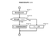
- FIG. 12 is a flowchart illustrating a process (hereinafter referred to as a thermal connection switching process S1200) performed by the calculation unit 1201 (thermal connection switching control unit) in the control method (1).
- a thermal connection switching process S1200 will be described with reference to FIG.
- the calculation unit 1201 acquires the battery temperature in real time (S1211), and compares the battery temperature with the threshold value TH (S1212). *
- the calculation unit 1201 controls the thermal connection switching device 220 via the battery pack communication unit 1210, and the heat conductor 211 of the battery pack 200. Is the motor drive control device 100 (S1213). Thereafter, the process returns to S1211.
- TH battery temperature ⁇ TH
- the calculation unit 1201 controls the thermal connection switching device 220 via the battery pack communication unit 1210, and the heat conductor 211 of the battery pack 200. Is the motor drive control device 100 (S1213). Thereafter, the process returns to S1211.
- the calculation unit 1201 controls the thermal connection switching device 220 via the battery pack communication unit 1210, and the heat conduction of the battery pack 200.
- the thermal connection destination of the body 211 is set as the frame 11 (S1214). Thereafter, the process returns to S1211.
- Control method (2) In the control method (1), the thermal connection destination of the heat conductor 211 is switched with the threshold value TH as a boundary. In the control method (2), in order to prevent chattering that may occur when the battery temperature is near the threshold value TH, a hysteresis width HYS is provided for the threshold value TH.
- the hysteresis width HYS is set to 10 ° C., for example (the same applies to the control method (3)).
- FIG. 13A is a diagram illustrating a control method according to the control method (2) when the battery temperature changes from a low temperature to a high temperature.
- a preset threshold value TH + hysteresis width HYS battery temperature ⁇ (TH + HYS)
- motor drive control of the thermal connection destination of the heat conductor 211 of the battery pack 200 is performed.
- the heat of the motor drive control device 100 is transmitted to the battery pack 200 as the device 100, and the temperature of the battery pack 200 (power storage element 201) is increased.
- the thermal connection destination of the heat conductor 211 of the battery pack 200 is the frame 11, and the heat of the battery pack 200 is The battery pack 200 (power storage element 201) is cooled by letting it escape to the frame 11.
- FIG. 13B is a diagram illustrating a control method according to the control method (2) when the battery temperature changes from a high temperature to a low temperature.
- a preset threshold value TH battery temperature ⁇ TH
- the thermal connection destination of the heat conductor 211 of the battery pack 200 is the frame 11, and the battery pack 200 Heat is released to the frame 11 to cool the battery pack 200 (power storage element 201).
- the thermal connection destination of the heat conductor 211 of the battery pack 200 is the motor drive control device 100, and the heat of the motor drive control device 100 is the battery pack. 200 to increase the temperature of the battery pack 200 (power storage element 201).
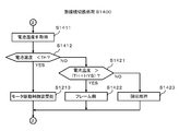
- FIG. 14 is a flowchart illustrating a process (hereinafter referred to as a thermal connection switching process S1400) performed by the calculation unit 1201 (thermal connection switching control unit) in the control method (2).
- a thermal connection switching process S1400 will be described with reference to FIG.
- the calculation unit 1201 acquires the battery temperature in real time (S1411), and first compares the battery temperature with the threshold value TH (S1412).
- the calculation unit 1201 controls the thermal connection switching device 220 via the battery pack communication unit 1210, and the heat conductor 211 of the battery pack 200. Is the motor drive control device 100 (S1413). Thereafter, the process returns to S1411.
- TH battery temperature ⁇ TH
- the calculation unit 1201 controls the thermal connection switching device 220 via the battery pack communication unit 1210, and the heat conductor 211 of the battery pack 200. Is the motor drive control device 100 (S1413). Thereafter, the process returns to S1411.
- the calculation unit 1201 compares the battery temperature with the threshold value TH + the hysteresis width HYS (S1421).
- threshold value TH + hysteresis width HYS battery temperature> (TH + HYS)
- operation unit 1201 controls thermal connection switching device 220 via battery pack communication unit 1210, and battery pack.
- the thermal connection destination of the 200 heat conductors 211 is the frame 11 (S1422). Thereafter, the process returns to S1411.
- operation unit 1201 When the battery temperature is equal to or less than threshold value TH + hysteresis width HYS (battery temperature ⁇ (TH + HYS)) (S1421: NO), operation unit 1201 maintains the current state of thermal connection switching device 220 (S1423). Thereafter, the process returns to S1411.
- threshold value TH + hysteresis width HYS battery temperature ⁇ (TH + HYS)
- control method (3) In the control method (3), thermal connection switching control is performed with reference to the motor drive control device temperature and the frame temperature in addition to the battery temperature.
- the frame 11 is at a high temperature.
- the thermal conductor 211 of the battery pack 200 is thermally connected to the frame 11, the temperature of the battery pack 200 rises and regenerative charging may be limited. There is sex. Therefore, when the temperature of the frame 11 is high, the connection destination of the heat conductor 211 of the battery pack 200 is opened (no connection destination) so that the temperature rise of the battery pack 200 is prevented.
- FIG. 15A is a diagram illustrating a control method according to the control method (3) when the battery temperature changes from a low temperature to a high temperature (battery temperature ⁇ (TH + HYS) range).
- battery temperature ⁇ (TH + HYS) range battery temperature ⁇ (TH + HYS) range.
- the thermal connection destination of the heat conductor 211 of the battery pack 200 is the motor drive control device 100, The heat of motor drive control device 100 is transmitted to battery pack 200 to increase the temperature of battery pack 200 (storage element 201).
- TH_Cnt second predetermined value (for example, about 5 ° C.) (motor drive control device temperature ⁇ TH_Cnt)
- TH_Cnt second predetermined value
- FIG. 15B is a diagram illustrating a control method according to the control method (3) when the battery temperature changes from a low temperature to a high temperature (battery temperature ⁇ (TH + HYS) range).
- battery temperature ⁇ battery temperature ⁇ (TH + HYS) range
- the thermal connection destination of the heat conductor 211 of the battery pack 200 is the frame 11, and the battery pack 200. The heat is released to the frame 11 to cool the battery pack 200 (power storage element 201).
- the connection destination of the heat conductor 211 of the battery pack 200 is opened. (No connection destination) to prevent the temperature of the battery pack 200 from rising due to the heat of the frame 11.
- FIG. 15C is a diagram illustrating a control method according to the control method (3) when the battery temperature changes from a high temperature to a low temperature (battery temperature ⁇ TH).
- the thermal connection destination of the heat conductor 211 of the battery pack 200 is the frame 11, and the heat of the battery pack 200 is To the frame 11 to cool the battery pack 200 (power storage element 201).
- the frame temperature is higher than the threshold TH_Body (TH_Body ⁇ frame temperature)
- the connection destination of the heat conductor 211 of the battery pack 200 is opened (no connection destination), and the battery pack 200 due to the heat of the frame 11 is used. Try to prevent the temperature from rising.
- FIG. 15D is a diagram illustrating a control method according to the control method (3) when the battery temperature changes from a high temperature to a low temperature (battery temperature ⁇ TH range).
- the thermal connection destination of the thermal conductor 211 of the battery pack 200 is the motor drive control device 100, and the motor drive The heat of the control device 100 is transmitted to the battery pack 200 to increase the temperature of the battery pack 200 (power storage element 201).
- a threshold TH_Cnt for example, about 5 ° C.
- motor drive control device temperature ⁇ TH_Cnt the connection destination of the heat conductor 211 of the battery pack 200 is opened ( No connection destination), and the temperature reduction of the battery pack 200 due to the heat deprived by the motor drive control device 100 is prevented.
- the current motor drive control device temperature may be used as the threshold value TH_Cnt.
- the heat conductor 211 of the battery pack 200 is thermally connected to the motor drive control device 100 to drive the motor.
- the heat of control device 100 can be transmitted to battery pack 200 to increase the temperature of battery pack 200 (power storage element 201).
- the current frame temperature may be used as the threshold value TH_Body.
- the thermal conductor 211 of the battery pack 200 is thermally connected to the frame 11 and the heat of the battery pack 200 is transferred to the frame 11.
- the battery pack 200 (power storage element 201) can be cooled by releasing the heat.
- FIG. 16 is a flowchart for explaining processing (hereinafter referred to as thermal connection switching processing S1600) performed by the calculation unit 1201 (thermal connection switching control unit) in the control method (3).
- thermal connection switching processing S1600 processing performed by the calculation unit 1201 (thermal connection switching control unit) in the control method (3).
- the thermal connection switching process S1600 will be described with reference to FIG.
- the calculation unit 1201 acquires the battery temperature, the frame temperature, and the vehicle body control device temperature in real time (S1611).
- the calculation unit 1201 first compares the battery temperature with the threshold value TH (S1612). When the battery temperature is lower than the threshold value TH (battery temperature ⁇ TH) (S1612: YES), the process proceeds to S1613. When the battery temperature is equal to or higher than the threshold value TH (battery temperature ⁇ TH) (S1612: YES), the process proceeds to S1621.
- the calculation unit 1201 determines whether or not the vehicle body control device temperature exceeds TH_Cnt.
- the calculation unit 1201 controls the thermal connection switching device 220 to control the thermal conductor 211 of the battery pack 200.
- the connection destination is the motor drive control device 100 (S1614). Thereafter, the process returns to S1611.
- the calculation unit 1201 controls the heat connection switching device 220 to heat the heat conductor 211 of the battery pack 200.
- a general connection destination is opened (no connection destination) (S1615). Thereafter, the process returns to S1611.
- the calculation unit 1201 compares the battery temperature with the threshold value TH + the hysteresis width HYS. When the battery temperature exceeds the threshold value TH + the hysteresis width HYS (battery temperature> (TH + HYS)) (S1621: YES), the process proceeds to S1622. When the battery temperature is equal to or less than threshold value TH + hysteresis width HYS (battery temperature ⁇ (TH + HYS)) (S1621: NO), operation unit 1201 maintains the current state of thermal connection switching device 220 (S1625). Thereafter, the process proceeds to S1611 (the state of the thermal connection switching device 220 is maintained as it is).
- the calculation unit 1201 compares the frame temperature with TH_Body. When the frame temperature is lower than TH_Body (frame temperature ⁇ TH_Body) (S1622: YES), the calculation unit 1201 controls the thermal connection switching device 220, and the thermal connection destination of the thermal conductor 211 of the battery pack 200 is defined as the frame 11. (S1623). Thereafter, the process returns to S1611.
- the calculation unit 1201 controls the thermal connection switching device 220 to open the thermal connection destination of the thermal conductor 211 of the battery pack 200. (No connection destination) is set (S1624). Thereafter, the process returns to S1611.
- the calculation unit 1201 may execute the three control methods (1) to (3) described above in an appropriate combination.
- the calculation unit 1201 may execute the thermal connection switching process S1600 when the battery temperature is lower than a predetermined temperature
- the calculation unit 1201 may execute the thermal connection switching process S1400 when the battery temperature is equal to or higher than the predetermined temperature.
- the hysteresis width is also obtained when the body controller temperature is compared with TH_Cnt (S1613 in FIG. 16) and when the frame temperature is compared with TH_Body (S1622 in FIG. 16). May be set to prevent chattering.
- the thermal connection switching device 220 is provided in the battery pack 200 and is controlled by the motor drive control device 100.
- a configuration corresponding to the thermal connection switching device 220 (The heat connection switching device 160) is provided in the motor drive control device 100, and the motor drive control device 100 controls this directly (without going through the battery pack communication unit 1210).
- the motor drive control device 100 by providing the motor drive control device 100 with a configuration corresponding to the thermal connection switching device 220 (thermal connection switching device 160), the configuration change of the existing battery pack 200 can be minimized.
- the electrically assisted bicycle 1 according to the second embodiment will be described with a focus on differences from the first embodiment.
- FIG. 17 is a diagram showing a configuration (block diagram) of the motor drive control device 100 of the second embodiment. As shown in the figure, in the second embodiment, a thermal connection switching device 160 is provided in the motor control circuit 120 of the motor drive control device 100.
- the thermal connection switching device 160 is configured using, for example, one or more electric relays. As in the first embodiment, the calculation unit 1201 controls the thermal connection switching device 160 based on the battery temperature, the motor drive control device temperature, and the frame temperature so that the battery temperature is maintained in an appropriate range as much as possible, and the heat conduction is performed. The connection destination of the body 211 is switched to any one of the motor drive control device 100, the frame 11, and the open (no connection).
- FIG. 18 is a diagram showing a configuration (block diagram) of the battery pack 200 of the second embodiment. Similar to the battery pack 200 of the first embodiment, the battery pack 200 of the second embodiment is provided with a heat conductor 211 so that heat can be efficiently exchanged with the power storage element 201. A part of the heat conductor 211 is thermally connected to the external connection terminal 71 of the battery pack 200.
- FIG. 19 shows a configuration example of the battery pack 200 and the connector base 130 of the second embodiment.
- the external connection terminals 51 to 53 of the battery pack 200 are electrically connected to the circuit board 1311 of the motor drive control device 100 through the corresponding terminals of the terminal group 1301 of the connector base 130.
- a thermal connection switching device 160 is provided on the connector base 130 or the board case 131.
- the external connection terminals 71 of the battery pack 200 are thermally connected to the terminals of the thermal connection switching device 160 via the corresponding terminals of the terminal group 1301 of the connector base 130. Connected to.
- FIG. 20 is a diagram illustrating functions provided in the battery pack side control circuit 204 of the battery pack 200 of the second embodiment and data stored in the battery pack side control circuit 204.
- the battery pack side control circuit 204 of the second embodiment does not have the thermal connection switching device control unit 414.
- FIGS. 21A to 21C show a switching mode of the thermal connection switching device 220 by the thermal connection switching control performed by the calculation unit 1201 (thermal connection switching control unit) of the motor drive control device 100 in the second embodiment.
- 21A shows a case where the connection destination of the heat conductor 211 is the motor drive control device 100 (heat conductor 150)
- FIG. 21B shows a case where the connection destination of the heat conductor 211 is the frame 11, and FIG. This is a case where the connection destination of the conductor 211 is open (no connection destination).
- the calculation unit 1201 (thermal connection switching control unit) of the motor drive control device 100 controls the thermal connection switching device 160, so that the thermal connection switching control shown in the first embodiment is performed. Thermal connection switching control similar to the specific example (control methods (1) to (3)) can be performed.
- the battery-assisted bicycle 1 is thermally disconnected from the power storage element 201 and the motor drive control device 100 when the battery temperature is equal to or higher than the threshold value TH. It is possible to prevent the performance from deteriorating.
- the battery-assisted bicycle 1 thermally connects the power storage element to the frame 11 and releases the heat of the power storage element 201. Can be prevented.
- the electric auxiliary vehicle is driven by human power and electric power assistance, it is required to reduce the weight.
- a simple configuration can be achieved without adding a configuration such as a cooling fan or a water cooling type cooling mechanism.
- a mechanism for cooling the storage element can be realized by the method.
- the electric assist bicycle 1 thermally separates the storage element 201 and the motor drive control device 100, so that the motor drive control device temperature is low as in winter. In addition, it is possible to prevent the motor drive control device 100 from being thermally connected to the storage element 201 at a low temperature and the charge / discharge performance from being deteriorated.
- the electric assist bicycle 1 thermally separates the power storage element 201 and the motor drive control device 100, so that the temperature of the predetermined part is high as in summer.
- the power storage element 201 is thermally connected to a predetermined portion, so that it is possible to prevent the power storage element 201 from becoming high temperature and the charge / discharge performance from being deteriorated.
Landscapes
- Engineering & Computer Science (AREA)
- Chemical & Material Sciences (AREA)
- Manufacturing & Machinery (AREA)
- Chemical Kinetics & Catalysis (AREA)
- Electrochemistry (AREA)
- General Chemical & Material Sciences (AREA)
- Mechanical Engineering (AREA)
- Transportation (AREA)
- Power Engineering (AREA)
- Combustion & Propulsion (AREA)
- Life Sciences & Earth Sciences (AREA)
- Sustainable Development (AREA)
- Sustainable Energy (AREA)
- Secondary Cells (AREA)
- Automation & Control Theory (AREA)
- Electric Propulsion And Braking For Vehicles (AREA)
- Charge And Discharge Circuits For Batteries Or The Like (AREA)
Abstract
Description
図11は制御方法(1)を説明するグラフである。同図に示すように、制御方法(1)では、電池温度が閾値TH(第1の所定値)未満(電池温度<TH)のときは、電池パック200の熱伝導体211の熱的な接続先をモータ駆動制御装置100とし、モータ駆動制御装置100の熱を電池パック200に伝えて電池パック200(蓄電素子201)の昇温を図る。一方、電池温度が閾値TH以上(TH≦電池温度)のときは、電池パック200の熱伝導体211の熱的な接続先をフレーム11とし、電池パック200の熱をフレーム11に逃がして電池パック200(蓄電素子201)の冷却を図る。尚、閾値THは、例えば、前述した回生充電可能温度範囲内又は無制限回生充電可能温度範囲内(例えば常温(≒20℃)程度)に設定する(後述の制御方法(2),(3)においても同様)。
制御方法(1)では、閾値THを境界として熱伝導体211の熱的な接続先を切り換えている。制御方法(2)では、電池温度が閾値TH近傍であるときに起こり得るチャタリングを防ぐため、閾値THにヒステリシス幅HYSを設ける。尚、ヒステリシス幅HYSは、例えば10℃に設定する(制御方法(3)の場合も同様とする)。
制御方法(3)では、電池温度に加え、モータ駆動制御装置温度及びフレーム温度をも参照しつつ、熱接続切換制御を行う。
ところで、演算部1201が、以上に説明した3つの制御方法(1)~(3)を適宜組み合わせて実行するようにしてもよい。例えば、電池温度が所定温度未満のときは演算部1201が熱接続切換処理S1600を実行し、上記所定温度以上のときは演算部1201が熱接続切換処理S1400を実行するようにしてもよい。
第1実施形態では、熱接続切換装置220を電池パック200に設け、これをモータ駆動制御装置100から制御するようにしているが、第2実施形態では、熱接続切換装置220に相当する構成(熱接続切換装置160)をモータ駆動制御装置100に設け、モータ駆動制御装置100が直接(電池パック通信部1210を介さずに)これを制御するようにする。尚、熱接続切換装置220に相当する構成(熱接続切換装置160)をモータ駆動制御装置100に設けることで、既存の電池パック200の構成変更を最小限に抑えることができる。以下、第1実施形態との相違点を中心として、第2実施形態の電動アシスト自転車1について説明する。
以上、詳述したように、本実施形態の電動アシスト自転車1にあっては、電池温度が閾値THのときはモータ駆動制御装置100の熱を利用して蓄電素子201を昇温することにより、蓄電素子201が低温となって充放電性能が低下するのを防ぐことができ、蓄電素子201を適正な温度範囲に維持して駆動力や回生による制動力を安定して得ることができる。
Claims (11)
- 蓄電素子に蓄えられている電力により電動補助車両に設けられているモータを駆動するとともに、前記モータの回生動作時に生じる電力により前記蓄電素子を充電するモータ駆動制御装置と、
前記蓄電素子の温度である蓄電素子温度を取得する蓄電素子温度取得部と、
前記蓄電素子と前記モータ駆動制御装置を熱的に接続もしくは切り離す熱接続切換装置と、
前記蓄電素子温度が第1の所定値未満のときに前記蓄電素子が前記モータ駆動制御装置と熱的に接続されるように前記熱接続切換装置を制御する熱接続切換制御部と、
を備える、
電動補助車両の駆動装置。 - 前記熱接続切換制御部は、前記蓄電素子温度が前記第1の所定値以上のときは前記蓄電素子と前記モータ駆動制御装置を熱的に切り離すように前記熱接続切換装置を制御する、
請求項1に記載の電動補助車両の駆動装置。 - 前記熱接続切換制御部は、前記蓄電素子温度が前記第1の所定値以上のときに前記蓄電素子と前記電動補助車両の所定部位を熱的に接続するように前記熱接続切換装置を制御する、
請求項2に記載の電動補助車両の駆動装置。 - 前記熱接続切換制御部は、前記蓄電素子温度が前記第1の所定値に所定のヒステリシス幅値を加えた温度以上のときは前記蓄電素子と前記モータ駆動制御装置を熱的に切り離すように前記熱接続切換装置を制御する、
請求項2に記載の電動補助車両の駆動装置。 - 前記モータ駆動制御装置の温度であるモータ駆動制御装置温度を取得するモータ駆動制御装置温度取得部を更に備え、
前記熱接続切換制御部は、前記蓄電素子温度が前記第1の所定値未満であり、かつ、前記モータ駆動制御装置温度が第2の所定値以下のときは、前記蓄電素子と前記モータ駆動制御装置を熱的に切り離すように前記熱接続切換装置を制御する、
請求項1に記載の電動補助車両の駆動装置。 - 前記所定部位の温度である所定部位温度を取得する所定部位温度取得部を更に備え、
前記熱接続切換制御部は、前記蓄電素子温度が前記第1の所定値以上であり、かつ、前記所定部位温度が第3の所定値以上のときは、前記蓄電素子と前記所定部位を熱的に切り離すように前記熱接続切換装置を制御する、
請求項3に記載の電動補助車両の駆動装置。 - 前記所定部位の温度である所定部位温度を取得する所定部位温度取得部を更に備え、
前記熱接続切換制御部は、前記蓄電素子温度が前記第1の所定値に所定のヒステリシス幅値を加えた温度以上であり、かつ、前記所定部位温度が第3の所定値以上のときは、前記蓄電素子と前記所定部位を熱的に切り離すように前記熱接続切換装置を制御する、
請求項3に記載の電動補助車両の駆動装置。 - 前記蓄電素子は、前記回生制御部による充電が可能な温度範囲である回生充電可能温度範囲を有し、
前記第1の所定値は、前記回生充電可能温度範囲内に設定される、
請求項1に記載の電動補助車両の駆動装置。 - 前記熱接続切換装置を備える、請求項1に記載の電動補助車両の駆動装置。
- 請求項1乃至10のいずれか一項に記載の前記駆動装置を備える電動補助車両。
- 請求項1に記載の前記蓄電素子及び前記熱接続切換装置を備える蓄電装置。
Priority Applications (2)
| Application Number | Priority Date | Filing Date | Title |
|---|---|---|---|
| JP2018503986A JP6577658B2 (ja) | 2016-03-11 | 2016-10-12 | 電動補助車両の駆動装置、電動補助車両、及び蓄電装置 |
| EP16893580.7A EP3427998A4 (en) | 2016-03-11 | 2016-10-12 | DRIVING DEVICE FOR BICYCLE WITH ELECTRIC AUXILIARY DRIVE, BICYCLE WITH ELECTRIC AUXILIARY DRIVE AND ELECTRICITY STORAGE DEVICE |
Applications Claiming Priority (2)
| Application Number | Priority Date | Filing Date | Title |
|---|---|---|---|
| JP2016-048311 | 2016-03-11 | ||
| JP2016048311 | 2016-03-11 |
Publications (1)
| Publication Number | Publication Date |
|---|---|
| WO2017154256A1 true WO2017154256A1 (ja) | 2017-09-14 |
Family
ID=59789305
Family Applications (1)
| Application Number | Title | Priority Date | Filing Date |
|---|---|---|---|
| PCT/JP2016/080172 Ceased WO2017154256A1 (ja) | 2016-03-11 | 2016-10-12 | 電動補助車両の駆動装置、電動補助車両、及び蓄電装置 |
Country Status (3)
| Country | Link |
|---|---|
| EP (1) | EP3427998A4 (ja) |
| JP (1) | JP6577658B2 (ja) |
| WO (1) | WO2017154256A1 (ja) |
Cited By (6)
| Publication number | Priority date | Publication date | Assignee | Title |
|---|---|---|---|---|
| JP2019068686A (ja) * | 2017-10-04 | 2019-04-25 | 株式会社豊田自動織機 | バッテリ式産業車両 |
| JP2020131898A (ja) * | 2019-02-19 | 2020-08-31 | 株式会社シマノ | 電力供給装置、充電装置、コンポーネント、および、制御方法 |
| CN112744124A (zh) * | 2020-04-22 | 2021-05-04 | 长城汽车股份有限公司 | 电池包加热的控制方法、装置及整车控制器 |
| JP2021104749A (ja) * | 2019-12-26 | 2021-07-26 | パナソニックIpマネジメント株式会社 | 自転車及びドライブユニット |
| JP2021187323A (ja) * | 2020-05-29 | 2021-12-13 | 株式会社シマノ | 人力駆動車用のドライブユニット |
| JP2025036510A (ja) * | 2019-06-17 | 2025-03-14 | 株式会社マキタ | 電池駆動式可搬用具 |
Citations (4)
| Publication number | Priority date | Publication date | Assignee | Title |
|---|---|---|---|---|
| JPH0624238A (ja) * | 1992-07-06 | 1994-02-01 | Nippondenso Co Ltd | バッテリ温度制御装置 |
| JPH08138762A (ja) * | 1994-11-14 | 1996-05-31 | Honda Motor Co Ltd | バッテリ温度調節装置 |
| JP2004362949A (ja) * | 2003-06-05 | 2004-12-24 | Sony Corp | 電池装置、電池加温方法、及び電動アシスト自転車 |
| WO2008096899A1 (ja) * | 2007-02-07 | 2008-08-14 | Toyota Jidosha Kabushiki Kaisha | 冷却システム |
Family Cites Families (3)
| Publication number | Priority date | Publication date | Assignee | Title |
|---|---|---|---|---|
| JP2004149001A (ja) * | 2002-10-30 | 2004-05-27 | Sanyo Electric Co Ltd | 電動自転車 |
| WO2005124964A1 (ja) * | 2004-06-16 | 2005-12-29 | Murata Manufacturing Co., Ltd. | 電池パックの保護回路および電池パック |
| US9368983B2 (en) * | 2011-12-15 | 2016-06-14 | The Boeing Company | Autonomous lithium-ion battery protection |
-
2016
- 2016-10-12 JP JP2018503986A patent/JP6577658B2/ja active Active
- 2016-10-12 EP EP16893580.7A patent/EP3427998A4/en not_active Withdrawn
- 2016-10-12 WO PCT/JP2016/080172 patent/WO2017154256A1/ja not_active Ceased
Patent Citations (4)
| Publication number | Priority date | Publication date | Assignee | Title |
|---|---|---|---|---|
| JPH0624238A (ja) * | 1992-07-06 | 1994-02-01 | Nippondenso Co Ltd | バッテリ温度制御装置 |
| JPH08138762A (ja) * | 1994-11-14 | 1996-05-31 | Honda Motor Co Ltd | バッテリ温度調節装置 |
| JP2004362949A (ja) * | 2003-06-05 | 2004-12-24 | Sony Corp | 電池装置、電池加温方法、及び電動アシスト自転車 |
| WO2008096899A1 (ja) * | 2007-02-07 | 2008-08-14 | Toyota Jidosha Kabushiki Kaisha | 冷却システム |
Non-Patent Citations (1)
| Title |
|---|
| See also references of EP3427998A4 * |
Cited By (11)
| Publication number | Priority date | Publication date | Assignee | Title |
|---|---|---|---|---|
| JP2019068686A (ja) * | 2017-10-04 | 2019-04-25 | 株式会社豊田自動織機 | バッテリ式産業車両 |
| JP2020131898A (ja) * | 2019-02-19 | 2020-08-31 | 株式会社シマノ | 電力供給装置、充電装置、コンポーネント、および、制御方法 |
| JP7579629B2 (ja) | 2019-02-19 | 2024-11-08 | 株式会社シマノ | 電力供給装置、および、制御方法 |
| JP2025036510A (ja) * | 2019-06-17 | 2025-03-14 | 株式会社マキタ | 電池駆動式可搬用具 |
| JP7835839B2 (ja) | 2019-06-17 | 2026-03-25 | 株式会社マキタ | 電池駆動式可搬用具 |
| JP2021104749A (ja) * | 2019-12-26 | 2021-07-26 | パナソニックIpマネジメント株式会社 | 自転車及びドライブユニット |
| JP7561362B2 (ja) | 2019-12-26 | 2024-10-04 | パナソニックIpマネジメント株式会社 | 自転車 |
| CN112744124A (zh) * | 2020-04-22 | 2021-05-04 | 长城汽车股份有限公司 | 电池包加热的控制方法、装置及整车控制器 |
| US12567616B2 (en) | 2020-04-22 | 2026-03-03 | Great Wall Motor Company Limited | Method for controlling heating of battery pack, computational processing device, and non-transitory computer readable storage medium |
| JP2021187323A (ja) * | 2020-05-29 | 2021-12-13 | 株式会社シマノ | 人力駆動車用のドライブユニット |
| JP7514656B2 (ja) | 2020-05-29 | 2024-07-11 | 株式会社シマノ | 人力駆動車用のドライブユニット |
Also Published As
| Publication number | Publication date |
|---|---|
| EP3427998A1 (en) | 2019-01-16 |
| JPWO2017154256A1 (ja) | 2018-10-04 |
| JP6577658B2 (ja) | 2019-09-18 |
| EP3427998A4 (en) | 2019-10-16 |
Similar Documents
| Publication | Publication Date | Title |
|---|---|---|
| JP6577658B2 (ja) | 電動補助車両の駆動装置、電動補助車両、及び蓄電装置 | |
| CN110316022B (zh) | 车辆的电源系统 | |
| US10857894B2 (en) | Control apparatus, electrical power storage apparatus and system for mobile object | |
| JP4931161B2 (ja) | バッテリ充電 | |
| EP2613420B1 (en) | Charge control device for electric vehicle | |
| RU2589530C1 (ru) | Силовая установка электромобиля, электромобиль и способ обогрева аккумуляторной батареи электромобиля | |
| JP5945768B2 (ja) | 電気自動車の廃熱管理システム及び管理方法 | |
| US20090021221A1 (en) | Voltage dividing vehicle heater system and method | |
| JP6438379B2 (ja) | 電動アシスト車及び蓄電装置 | |
| KR20070076544A (ko) | 차량 추진 시스템 | |
| EP2610102A2 (en) | Controller for vehicle and vehicle including the controller | |
| JP7746019B2 (ja) | 電源システム | |
| KR20210053711A (ko) | 배터리 팩 및 배터리 팩의 제어방법 | |
| JP3491528B2 (ja) | 電気自動車の充電装置 | |
| JP7472189B2 (ja) | 温調装置及び車両 | |
| WO2013174275A1 (en) | Power system of electric vehicle, electric vehicle comprising the same and method for heating battery group of electric vehicle | |
| JP6280421B2 (ja) | 電池加温システム | |
| CN110957703A (zh) | 主继电器保护装置 | |
| JP2004022496A (ja) | 薄型電池による組電池の温度検出装置 | |
| CN221497678U (zh) | 一种自主供电装置及包含该装置的机动车辆 | |
| JP7696735B2 (ja) | 電源システム | |
| CN208035982U (zh) | 一种通过电机控制器实现动力电池交流快充的装置 | |
| CN203085712U (zh) | 一种用于电动车电池的加热保温系统 | |
| CN105564260B (zh) | 一种车辆控制器和车辆 | |
| JP2011223839A (ja) | 車両の電源装置 |
Legal Events
| Date | Code | Title | Description |
|---|---|---|---|
| ENP | Entry into the national phase |
Ref document number: 2018503986 Country of ref document: JP Kind code of ref document: A |
|
| NENP | Non-entry into the national phase |
Ref country code: DE |
|
| WWE | Wipo information: entry into national phase |
Ref document number: 2016893580 Country of ref document: EP |
|
| ENP | Entry into the national phase |
Ref document number: 2016893580 Country of ref document: EP Effective date: 20181011 |
|
| 121 | Ep: the epo has been informed by wipo that ep was designated in this application |
Ref document number: 16893580 Country of ref document: EP Kind code of ref document: A1 |