WO2017154265A1 - 固体酸化物型燃料電池 - Google Patents
固体酸化物型燃料電池 Download PDFInfo
- Publication number
- WO2017154265A1 WO2017154265A1 PCT/JP2016/083030 JP2016083030W WO2017154265A1 WO 2017154265 A1 WO2017154265 A1 WO 2017154265A1 JP 2016083030 W JP2016083030 W JP 2016083030W WO 2017154265 A1 WO2017154265 A1 WO 2017154265A1
- Authority
- WO
- WIPO (PCT)
- Prior art keywords
- fuel cell
- flow path
- air flow
- auxiliary layer
- solid oxide
- Prior art date
- Legal status (The legal status is an assumption and is not a legal conclusion. Google has not performed a legal analysis and makes no representation as to the accuracy of the status listed.)
- Ceased
Links
Images




Classifications
-
- H—ELECTRICITY
- H01—ELECTRIC ELEMENTS
- H01M—PROCESSES OR MEANS, e.g. BATTERIES, FOR THE DIRECT CONVERSION OF CHEMICAL ENERGY INTO ELECTRICAL ENERGY
- H01M8/00—Fuel cells; Manufacture thereof
- H01M8/02—Details
- H01M8/0202—Collectors; Separators, e.g. bipolar separators; Interconnectors
- H01M8/0204—Non-porous and characterised by the material
- H01M8/0206—Metals or alloys
-
- H—ELECTRICITY
- H01—ELECTRIC ELEMENTS
- H01M—PROCESSES OR MEANS, e.g. BATTERIES, FOR THE DIRECT CONVERSION OF CHEMICAL ENERGY INTO ELECTRICAL ENERGY
- H01M8/00—Fuel cells; Manufacture thereof
- H01M8/10—Fuel cells with solid electrolytes
- H01M8/12—Fuel cells with solid electrolytes operating at high temperature, e.g. with stabilised ZrO2 electrolyte
- H01M8/1233—Fuel cells with solid electrolytes operating at high temperature, e.g. with stabilised ZrO2 electrolyte with one of the reactants being liquid, solid or liquid-charged
-
- H—ELECTRICITY
- H01—ELECTRIC ELEMENTS
- H01M—PROCESSES OR MEANS, e.g. BATTERIES, FOR THE DIRECT CONVERSION OF CHEMICAL ENERGY INTO ELECTRICAL ENERGY
- H01M8/00—Fuel cells; Manufacture thereof
- H01M8/02—Details
- H01M8/0202—Collectors; Separators, e.g. bipolar separators; Interconnectors
- H01M8/023—Porous and characterised by the material
- H01M8/0232—Metals or alloys
-
- H—ELECTRICITY
- H01—ELECTRIC ELEMENTS
- H01M—PROCESSES OR MEANS, e.g. BATTERIES, FOR THE DIRECT CONVERSION OF CHEMICAL ENERGY INTO ELECTRICAL ENERGY
- H01M8/00—Fuel cells; Manufacture thereof
- H01M8/02—Details
- H01M8/0271—Sealing or supporting means around electrodes, matrices or membranes
- H01M8/0273—Sealing or supporting means around electrodes, matrices or membranes with sealing or supporting means in the form of a frame
-
- H—ELECTRICITY
- H01—ELECTRIC ELEMENTS
- H01M—PROCESSES OR MEANS, e.g. BATTERIES, FOR THE DIRECT CONVERSION OF CHEMICAL ENERGY INTO ELECTRICAL ENERGY
- H01M8/00—Fuel cells; Manufacture thereof
- H01M8/24—Grouping of fuel cells, e.g. stacking of fuel cells
- H01M8/241—Grouping of fuel cells, e.g. stacking of fuel cells with solid or matrix-supported electrolytes
- H01M8/2425—High-temperature cells with solid electrolytes
- H01M8/2432—Grouping of unit cells of planar configuration
-
- H—ELECTRICITY
- H01—ELECTRIC ELEMENTS
- H01M—PROCESSES OR MEANS, e.g. BATTERIES, FOR THE DIRECT CONVERSION OF CHEMICAL ENERGY INTO ELECTRICAL ENERGY
- H01M8/00—Fuel cells; Manufacture thereof
- H01M8/10—Fuel cells with solid electrolytes
- H01M8/12—Fuel cells with solid electrolytes operating at high temperature, e.g. with stabilised ZrO2 electrolyte
- H01M2008/1293—Fuel cells with solid oxide electrolytes
-
- Y—GENERAL TAGGING OF NEW TECHNOLOGICAL DEVELOPMENTS; GENERAL TAGGING OF CROSS-SECTIONAL TECHNOLOGIES SPANNING OVER SEVERAL SECTIONS OF THE IPC; TECHNICAL SUBJECTS COVERED BY FORMER USPC CROSS-REFERENCE ART COLLECTIONS [XRACs] AND DIGESTS
- Y02—TECHNOLOGIES OR APPLICATIONS FOR MITIGATION OR ADAPTATION AGAINST CLIMATE CHANGE
- Y02E—REDUCTION OF GREENHOUSE GAS [GHG] EMISSIONS, RELATED TO ENERGY GENERATION, TRANSMISSION OR DISTRIBUTION
- Y02E60/00—Enabling technologies; Technologies with a potential or indirect contribution to GHG emissions mitigation
- Y02E60/30—Hydrogen technology
- Y02E60/50—Fuel cells
Definitions
- the present invention relates to a solid oxide fuel cell, and more particularly to a solid oxide fuel cell that prevents an increase in electrical resistance due to separation of contacts.
- a solid oxide fuel cell permeates gas through an air electrode (cathode) that is an electrode through which a solid oxide electrolyte layer and gas permeate.
- a fuel cell unit including a fuel electrode (anode) and a current collector are included.
- the fuel cell generates power by supplying a fuel gas such as hydrogen or hydrocarbon to the fuel electrode and supplying an oxygen-containing gas such as air to the other air electrode, using the solid oxide electrolyte layer as a partition.
- a fuel gas such as hydrogen or hydrocarbon
- an oxygen-containing gas such as air
- the current collector is in contact with the fuel cell unit and collects the electric charge of the fuel cell unit, and forms a fuel gas channel or an air channel between the fuel cell unit and the current collector. .
- the air electrode of the fuel cell unit is made of a metal oxide, and the metal oxide has a higher electric resistance than a metal.
- Patent Document 1 discloses a fuel cell stack in which a porous metal such as an expanded metal is provided between a carbon bipolar plate forming a gas flow path and a membrane-electrode assembly. Yes.
- the solid oxide fuel cell has a high operating temperature, and in order to shorten the start-up time from the cold, if a high temperature gas is allowed to flow through the gas flow path and the temperature is rapidly raised, A temperature difference with the casing increases, and a large thermal expansion difference occurs between the fuel cell unit and the casing.
- a fuel cell unit in which a fuel electrode, an air electrode, and a solid oxide electrolyte layer are laminated has a dense metal particle, oxide particle, etc., so that if the expansion due to thermal expansion is restricted, a large curve deformation occurs. Is likely to occur.
- the current collection auxiliary layer provided between the air electrode and the current collector of the fuel cell unit and forming a conductive path from the air electrode to the current collector has the air in the air flow path as the air electrode. It has a large number of large gaps to be supplied and is sparser than the fuel cell unit.
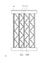
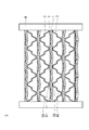
- a current collector formed by dividing a plurality of air flow paths or a plurality of fuel flow paths is a current collecting auxiliary layer or a fuel cell unit as shown in FIG. 1 or FIG.
- the air channel or the fuel channel is fixed in the extending direction.
- the curved deformation in the extending direction of the air flow path or the fuel flow path is limited, and the curved deformation of the fuel cell unit is likely to occur in a direction orthogonal to the extending direction of the air flow path or the fuel flow path.
- the current collection auxiliary layer has a high bending rigidity, the current collection is caused by the deformation of the fuel cell unit due to thermal expansion.
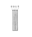
- the auxiliary layer cannot follow, and as shown in FIG. 3, the contact between the fuel cell unit and the current collecting auxiliary layer is separated in the direction orthogonal to the extending direction of the air flow path, and the electric resistance is increased.
- the present inventor has made the bending rigidity of the current collecting auxiliary layer of the solid oxide fuel cell smaller in the direction perpendicular to this direction than in the gas flow path direction.
- the inventors have found that the contact between the current collecting auxiliary layer and the air electrode can be prevented from separating while obtaining the electric resistance reducing effect of the current collecting auxiliary layer, and the present invention has been completed.
- the solid oxide fuel cell of the present invention includes a fuel cell unit in which a fuel electrode, a solid electrolyte, and an air electrode are sequentially laminated, a current collecting auxiliary layer that is laminated on the air electrode side of the fuel cell unit, and the air electrode.
- the fuel cell unit is divided and formed by a current collector fixed to the fuel electrode side, and extends in the same direction in a direction perpendicular to the stacking direction of the fuel cell unit.
- An electric body is fixed to the current collecting auxiliary layer at a first fixing portion extending in the extending direction of the air flow path, and the current collector on the fuel electrode side extends in the extending direction of the fuel gas flow path.
- the second fixed portion is fixed to the fuel electrode side of the fuel cell unit.
- assistant layer is smaller in the direction orthogonal to this direction than the extending direction of the said air flow path.
- the bending rigidity of the current collecting auxiliary layer is made smaller in the direction perpendicular to this direction than the extending direction of the gas flow path, following the curved deformation of the fuel cell unit, peeling of the current collecting auxiliary layer can be prevented, and an increase in electrical resistance can be prevented.
- the solid oxide fuel cell of the present invention will be described in detail.
- the solid oxide fuel cell C includes a fuel cell unit 1, a current collecting auxiliary layer 2, and a current collector 3.
- the fuel cell unit includes a fuel electrode 11, as shown in FIG.
- a solid electrolyte layer 12 and an air electrode 13 are laminated in order, and are supported by a porous metal support 14.
- the solid oxide type fuel cell includes an electrolyte-supported cell (ESC) with a thick electrolyte, an anode-supported cell (ASC) with a thick anode, and a cathode-supported type (Cathode with a thick cathode).
- ESC electrolyte-supported cell
- ASC anode-supported cell
- CSC cathode-supported type
- CSC -Supported Cell
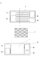
- FIG. 5 is an exploded view illustrating the configuration of the solid oxide fuel cell.
- the fuel cell unit 1 is formed by laminating the porous metal support 14, the fuel electrode 11, the solid electrolyte layer 12, and the air electrode 13 in this order at the position indicated by the dotted line in FIG. 5.
- a frame 15 is provided on the outer edge of the porous metal support 14.
- a current collecting auxiliary layer and a current collector are sequentially laminated on the surface opposite to the porous metal support side of the fuel cell unit, and the current collector is porous to the adjacent solid oxide fuel cell. It has a structure fixed to the metal support 14.
- the frame 15 and the current collector 3 have a substantially rectangular shape having substantially the same vertical and horizontal dimensions, and the fuel cell unit 1 and the frame 15 and the current collector 3 are fixed and overlapped to form a solid oxide fuel cell. C is formed.
- the current collector 3 has a corrugated cross section in the short side direction at a central portion corresponding to the fuel cell unit 1. This wave shape is continuous in the long side direction as shown in FIG. As a result, the wave-shaped convex portion of the current collector 3, that is, the rib portion is fixed to the current collection auxiliary layer 2 or the porous metal support 14 of the adjacent solid oxide fuel cell, so A gas flow path is formed.
- FIG. 1 is a cross-sectional view taken along the line AA ′ in FIG.
- 1 is a fuel cell unit
- 2 is a current collecting auxiliary layer
- 3 is a current collector
- AG is a fuel gas flow path
- CG is an air flow path
- 4 is a housing.
- the plurality of fuel gas flow paths AG are defined by a current collector fixed to the fuel electrode side of the fuel cell unit 1, and the plurality of air flow paths CG are fixed to the current collecting auxiliary layer. It is formed by partitioning with a current collector.
- the air flow path and the fuel gas flow path extend in the same direction in a direction perpendicular to the stacking direction of the fuel cell units,
- the current collector on the air electrode side is fixed to the current collecting auxiliary layer at a first fixing portion extending in the extending direction of the air flow path, and the current collector on the fuel electrode side is fixed to the fuel gas flow path.
- the second fixing portion extending in the extending direction is fixed to the fuel electrode side of the fuel cell unit.
- the current collection auxiliary layer 2 of the present invention has anisotropy in bending rigidity in the plane direction of the fuel cell unit 1.
- the bending rigidity in the above direction can be reduced without reducing the conductivity of the current collection auxiliary layer.
- the bending rigidity of the unit 1 can be made smaller. Then, since the current collection auxiliary layer 2 is pulled and deformed due to the curved deformation of the fuel cell unit 1, the contact between the current collection auxiliary layer 2 and the fuel cell unit 1 does not leave.
- the contact between the current collecting auxiliary layer 2 and the air electrode 13 is maintained, and the increase in resistance per unit area (ASR) of the solid oxide fuel cell C can be suppressed by at least 25%.
- the solid oxide fuel cell C of the present invention has a cross-section in which the current collector 3 is provided symmetrically with the fuel cell unit 1 and the current collection auxiliary layer 2 interposed therebetween (hereinafter referred to as “line oxide”). , Sometimes referred to as a current collector symmetrical laminate type).
- the current collector symmetrically stacked solid oxide fuel cell includes a fuel cell unit 1 in which a first fixing portion of the current collector 3 on the air electrode side and a second fixing portion of the current collector 3 on the fuel electrode side are included. It has the area
- the fuel cell unit is sandwiched by the overlapping region of the first fixed portion and the second fixed portion from the stacking direction, the curved deformation in the extending direction of the air flow path is strongly restricted by the current collector, and the first Separation of the fixing part and the second fixing part is prevented.
- the fuel cell unit is pressed by two current collectors, no shear force is generated, and the fuel cell unit can be prevented from cracking.
- the ratio (S / L) of the bending rigidity (S) in the direction orthogonal to the extending direction of the air flow path of the current collecting auxiliary layer 2 and the bending rigidity (L) in the air flow path direction is determined by the current collecting auxiliary layer 2. Depending on the material, etc., it is preferably 1/100 to 99/100.
- the current collecting auxiliary layer may not follow the curved deformation of the fuel cell unit, and the contact may be separated, and the current collecting auxiliary layer follows the curved deformation of the fuel cell unit. In order to do so, it is necessary to make the whole current collection auxiliary layer thin, and the conductivity of the whole current collection auxiliary layer is lowered.
- the bending rigidity of the current collection auxiliary layer 2 refers to the bending rigidity per unit length in the direction in which the air flow path extends or in the direction orthogonal to the direction in which the air flow path extends. Does not mean the bending rigidity of a single wire constituting the wire.
- the bending stiffness can be expressed as E ⁇ I.
- E represents a Young's modulus
- I represents a cross-sectional secondary moment.
- the Young's modulus is a value specific to the material constituting the current collection auxiliary layer 2, and the cross-sectional secondary moment is a portion other than the bond part B where the wire and the wire of the current collection auxiliary layer 2 shown in FIG. It is the value which calculated
- the bending stiffness in the direction of extension of the air flow path is the product of the integrated value of the cross-sectional second moment of the wire per unit length when cut in the direction orthogonal to the direction of extension of the air flow path and the Young's modulus.
- the bending stiffness in the direction perpendicular to the direction of extension of the air flow path is the integrated value of the cross-sectional second moment of the wire per unit length when cut in the direction of extension of the air flow path and the Young's modulus. Is the product.
- cermet of Ni and stabilized zirconia, CeO 2 to which Sm 2 O 3 , Gd 2 O 3 or the like is added can be used.
- Solid electrolyte layer 12 examples include stabilized zirconia added with Y 2 O 3 or Sc 2 O 3 , CeO 2 added with Sm 2 O 3 , Gd 2 O 3, or the like (La, Sr) (Gd , Mg) O 3 and other solid oxides such as lanthanum gallate having a perovskite structure can be used.
- Air electrode As the air electrode 13, for example, an oxide electrode having a perovskite structure such as (Ls, Sr) CoO 3 or (Sm, Sr) CoO 3 can be used.
- the porous metal support 14 supports the fuel cell unit 1 from the fuel electrode side.
- porous metal support 14 one obtained by press-molding metal particles can be used.
- metal particles such as stainless steel, iron (Fe), nickel (Ni), copper (Cu), platinum (Pt), and silver (Ag), can be mentioned, for example.
- the current collection auxiliary layer stainless steel, an alloy mainly composed of nickel (Ni) or chromium (Cr), or a metal expanded metal such as platinum (Pt) and silver (Ag), a punching metal, A metal mesh etc. can be mentioned.
- Examples of a method for imparting anisotropy to the bending rigidity of the current collecting auxiliary layer 2 include a method of forming a mesh of openings having different sizes in the long direction (LW) and the short direction (SW), and an orthogonal wire
- LW long direction
- SW short direction
- the method of changing the integrated value of the cross-sectional second moment, the method of changing the width of the orthogonal wire, the method of changing the height of the orthogonal wire, the method of changing the number of the orthogonal wires, and two or more types of wires having different Young's moduli The method of use etc. can be mentioned.
- Examples of the current collector 3 include a corrugated plate obtained by pressing a flat plate made of metal such as stainless steel or an alloy mainly composed of nickel (Ni) or chromium (Cr). It is preferable that the upper current collector has a displacement absorbing portion bent between a first fixing portion fixed to the current collecting auxiliary layer and a second fixing portion fixed to the adjacent fuel cell unit.
- first fixing portion 31 for fixing the current collector 3 and the current collecting auxiliary layer 2 and the second fixing portion 32 for fixing the current collector 3 and the porous metal support 14 are pressed, bonded, It can be fixed by welding or the like, but is preferably fixed by welding.
- the current collector 3, the current collection auxiliary layer 2 and the porous metal support 14 are welded to form a metal joint and fixed, whereby the current collector 3, the current collection auxiliary layer 2 and the porous metal support 14 are fixed. 14, a conductive path is formed, and resistance can be reduced to improve power generation efficiency.
- a metal joint means a metal joint directly joined without an oxide film.
- a contact material layer can be provided between the air electrode of the fuel cell unit and the current collecting auxiliary layer.
- the contact material layer improves the bonding force between the air electrode 13 of the fuel cell unit 1 and the current collection auxiliary layer 2.
- a contact material having flexibility such as a paste
- the wire of the current collecting auxiliary layer enters the contact material layer and is firmly bonded. Can do.
- the contact material layer for example, a paste such as platinum (Pt) and silver (Ag), an oxide paste having a perovskite structure such as (Ls, Sr) CoO 3 and (Sm, Sr) CoO 3 , and the above solid oxide
- a paste such as platinum (Pt) and silver (Ag)
- an oxide paste having a perovskite structure such as (Ls, Sr) CoO 3 and (Sm, Sr) CoO 3
- the metal oxide which comprises a physical layer can be used, and these can be used 1 type or in mixture of 2 or more types.
- FIG. 8 is a view showing a state seen from the current collector side when cut along BB ′ shown in FIG.
- the above expanded metal is a metal plate that has a zigzag cut and is formed to form a diamond-shaped or turtle-shaped mesh, and the bending rigidity in the short direction (SW) of the mesh is the bending in the long direction (LW). It is smaller than the rigidity.
- the bending rigidity of the current collecting auxiliary layer is more perpendicular to this direction than the extending direction of the air flow path. Get smaller. Therefore, the current collection auxiliary layer 2 follows the curved deformation of the fuel cell unit 1 and can prevent the current collection auxiliary layer 2 and the fuel cell unit 1 from peeling off.
- FIG. 9 shows a schematic diagram of this embodiment.
- FIG. 9 is a view showing a state viewed from the current collector side when cut along BB ′ shown in FIG.
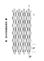
- a metal mesh is used for the current collecting auxiliary layer, and the angle at which the wires constituting the metal mesh intersect with each other in the oxygen-containing gas flow channel direction rather than the oxygen-containing gas flow channel direction.
- the one in which the orthogonal direction is large, that is, the long mesh direction (LW) is directed to the oxygen-containing gas flow path direction.
- the bending rigidity of the current collecting auxiliary layer is more perpendicular to this direction than the extending direction of the air flow path. Get smaller. Therefore, the current collecting auxiliary layer follows the curved deformation of the fuel cell unit, and peeling of the current collecting auxiliary layer and the fuel cell unit can be prevented.
- FIG. 10 shows a schematic diagram of this embodiment.
- FIG. 10 is a view showing a state seen from the current collector side when cut along BB ′ shown in FIG.
- a metal mesh is used for the current collection auxiliary layer.
- the metal mesh is a wire rod in which the extending direction of the air flow channel and the wire extending in the orthogonal direction are orthogonal to each other, and the number of wires in the air flow channel extending direction extends in the orthogonal direction. Is more than the number of
- the bending rigidity of the current collecting auxiliary layer becomes smaller in the direction orthogonal to the extending direction of the air flow path. Therefore, the current collecting auxiliary layer follows the curved deformation of the fuel cell unit, and peeling of the current collecting auxiliary layer and the fuel cell unit can be prevented.
- FIG. 11 shows a schematic diagram of this embodiment.
- FIG. 11 is a diagram showing a state seen from the current collector side when cut along BB ′ shown in FIG.
- a metal mesh is used for the current collection auxiliary layer.
- the metal mesh is such that the extending direction of the air flow path and the wire extending in the orthogonal direction are orthogonal to each other, and the cross-sectional secondary moment of the wire in the extending direction of the air flow path is in the orthogonal direction. It is larger than the cross-sectional second moment of the elongated wire.
- the bending moment of the current collecting auxiliary layer is smaller in the direction orthogonal to the direction of extension of the air flow path than in the direction of extension of the air flow path because the moment of inertia of the wire in the direction orthogonal to the direction of extension of the air flow path is small. Become. Therefore, the current collecting auxiliary layer follows the curved deformation of the fuel cell unit, and peeling of the current collecting auxiliary layer and the fuel cell unit can be prevented.
Landscapes
- Life Sciences & Earth Sciences (AREA)
- Engineering & Computer Science (AREA)
- Manufacturing & Machinery (AREA)
- Sustainable Development (AREA)
- Sustainable Energy (AREA)
- Chemical & Material Sciences (AREA)
- Chemical Kinetics & Catalysis (AREA)
- Electrochemistry (AREA)
- General Chemical & Material Sciences (AREA)
- Fuel Cell (AREA)
Abstract
Description
そして、上記集電補助層の曲げ剛性が、上記空気流路の延在方向よりもこの方向と直交する方向において小さいことを特徴とする。
上記固体酸化物型燃料電池Cは、燃料電池ユニット1と集電補助層2と、集電体3とを備えるものであり、上記燃料電池ユニットは、図4に示すように、燃料極11、固体電解質層12、空気極13を順に積層したものであり、多孔質金属支持体14で支持される。
上記燃料電池ユニット1は、図5中、点線で示す位置に上記多孔質金属支持体14、燃料極11、固体電解質層12、及び空気極13が順に積層されて成る。そして、上記多孔質金属支持体14の外縁にフレーム15を備える。
これにより、集電体3の波形状の凸部分、すなわち、リブ部が集電補助層2又は隣接する固体酸化物型燃料電池の多孔質金属支持体14に固定され、波形状における各凹部分にガス流路が形成される。
図1中、1は燃料電池ユニット、2は集電補助層、3は集電体、AGは燃料ガス流路、CGは空気流路、4は筐体である。
そして、上記空気流路と上記燃料ガス流路は、上記燃料電池ユニットの積層方向と垂直な方向において同方向に延在しており、
空気極側の上記集電体が上記空気流路の延在方向に伸びた第1固定部で上記集電補助層と固定され、且つ燃料極側の上記集電体が上記燃料ガス流路の延在方向に伸びた第2固定部で上記燃料電池ユニットの燃料極側と固定されている。
但し、Eはヤング率、Iは断面二次モーメントを表わす。
上記燃料極11としては、例えば、Niと安定化ジルコニアのサーメットや、Sm2O3やGd2O3などを添加したCeO2などが使用できる。
上記固体電解質層12としては、例えば、Y2O3やSc2O3を添加した安定化ジルコニアや、Sm2O3やGd2O3などを添加したCeO2、(La,Sr)(Gd,Mg)O3などのペロブスカイト構造を有するランタンガレートなどの固体酸化物を使用できる。
上記空気極13としては、例えば、(Ls,Sr)CoO3や(Sm,Sr)CoO3などのペロブスカイト構造を有する酸化物電極などが使用できる。
上記多孔質金属支持体14は、燃料電池ユニット1をその燃料極側から支持するものである。
上記金属粒子としては、例えば、ステンレス鋼、鉄(Fe)、ニッケル(Ni)、銅(Cu)、白金(Pt)及び銀(Ag)などの金属粒子を挙げることができる。
上記集電補助層2としては、ステンレス鋼や、ニッケル(Ni)又はクロム(Cr)を主成分とする合金、または白金(Pt)及び銀(Ag)などの金属製のエキスパンドメタル、パンチングメタル、金属メッシュ等を挙げることができる。
上記集電体3としては、例えば、ステンレス鋼や、ニッケル(Ni)又はクロム(Cr)を主成分とする合金などの金属製の平板をプレス加工した波板を挙げることができる。
上集電体は、集電補助層と固定する第1固定部と、隣接する燃料電池ユニットと固定する第2固定部との間に屈曲した変位吸収部を有するものであることが好ましい。
本発明の固体酸化物型燃料電池は、上記燃料電池ユニットの空気極と上記集電補助層との間に接点材層を設けることができる。
ペースト状等の柔軟性を有する状態の接点材に集電補助層2を積層し、上記空気極13と共に焼結することで、集電補助層の線材が接点材層に入り込み強固に接合させることができる。
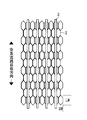
本実施形態は、集電補助層2にエキスパンドメタルを用いるものである。 図8は、図1に示すB-B’で切ったときに集電体側から見た状態を示す図である。
上記エキスパンドメタルは、金属板に千鳥状に切れ目を入れて広げ、菱形や亀甲形の網目を形成したものであり、網目の短目方向(SW)の曲げ剛性が長目方向(LW)の曲げ剛性よりも小さいものである。
したがって、集電補助層2が燃料電池ユニット1の湾曲変形に追従し、集電補助層2と燃料電池ユニット1との剥がれを防止することができる。
図9に本実施形態の概略図を示す。図9は、図1に示すB-B’で切ったときに集電体側から見た状態を示す図である。
したがって、集電補助層が燃料電池ユニットの湾曲変形に追従し、集電補助層と燃料電池ユニットとの剥がれを防止することができる。
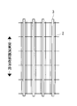
図10に本実施形態の概略図を示す。図10は、図1に示すB-B’で切ったときに集電体側から見た状態を示す図である。
そして、上記金属メッシュが、上記空気流路の延在方向とその直交方向に伸びた線材が相互に直交し、且つ上記空気流路延在方向の線材の本数が、その直交方向に伸びた線材の本数よりも多いものである。
したがって、集電補助層が燃料電池ユニットの湾曲変形に追従し、集電補助層と燃料電池ユニットとの剥がれを防止することができる。
図11に本実施形態の概略図を示す。図11は、図1に示すB-B’で切ったときに集電体側から見た状態を示す図である。
そして、上記金属メッシュが、上記空気流路の延在方向とその直交方向に伸びた線材が相互に直交し、且つ空気流路の延在方向の線材の断面二次モーメントが、その直交方向に伸びた線材の断面二次モーメントよりも大きいものである。
したがって、集電補助層が燃料電池ユニットの湾曲変形に追従し、集電補助層と燃料電池ユニットとの剥がれを防止することができる。
1 燃料電池ユニット
11 燃料極
12 固体電解質層
13 空気極
14 多孔質金属支持体
15 フレーム
2 集電補助層
3 集電体
31 第1固定部
32 第2固定部
4 筐体
AG 燃料ガス流路
CG 酸素含有ガス流路
H1~H4 マニホールド
Claims (8)
- 燃料極、固体電解質、空気極を順に積層した燃料電池ユニットと、
上記燃料電池ユニットの空気極側に積層した集電補助層と、
上記空気極側に配設した複数の空気流路と、
上記燃料極側に配設した複数の燃料ガス流路と、
を備えた固体酸化物型燃料電池であって、
上記空気流路と上記燃料ガス流路は、それぞれ上記集電補助層又は上記燃料電池ユニットの燃料極側に固定された集電体で区画して形成され、かつ上記燃料電池ユニットの積層方向と垂直な方向において同方向に延在しており、
空気極側の上記集電体が上記空気流路の延在方向に伸びた第1固定部で上記集電補助層と固定され、且つ燃料極側の上記集電体が上記燃料ガス流路の延在方向に伸びた第2固定部で上記燃料電池ユニットの燃料極側と固定されたものであり、
上記集電補助層の曲げ剛性が、上記空気流路の延在方向よりもこの方向と直交する方向において小さい、ことを特徴とする固体酸化物型燃料電池。 - 上記第1固定部と上記第2固定部が、上記燃料電池ユニットの積層方向において重なる領域を有することを特徴とする請求項1に記載の固体酸化物型燃料電池。
- 上記集電補助層の空気流路の延在方向と直交する方向における曲げ剛性(S)と空気流路の延在方向における曲げ剛性(L)との比(S/L)が、1/100~99/100であることを特徴とする請求項1又は2に記載の固体酸化物型燃料電池。
- 上記集電補助層は、上記空気流路の延在方向とその直交方向に伸びた線材が相互に直交した金属メッシュから成り、
上記空気流路の延在方向の線材の断面二次モーメントが、その直交方向に伸びた線材の断面二次モーメントよりも大きいことを特徴とする請求項1~3のいずれか1つの項に記載の固体酸化物型燃料電池。 - 上記集電補助層は、上記空気流路の延在方向とその直交方向に伸びた線材が相互に直交した金属メッシュから成り、
上記空気流路の延在方向の線材の本数が、その直交方向に伸びた線材の本数よりも多いことを特徴とする請求項1~3のいずれか1つの項に記載の固体酸化物型燃料電池。 - 上記集電補助層がエキスパンドメタル、金属メッシュ又はパンチングメタルから成り、
その目開きが、上記空気流路の延在方向よりもその直交方向において小さいことを特徴とする請求項1~3のいずれか1つの項に記載の固体酸化物型燃料電池。 - 上記第1固定部と上記集電補助層が溶接されていることを特徴とする請求項1~6のいずれか1つの項に記載の固体酸化物型燃料電池。
- 上記燃料電池ユニットが、その燃料極に積層した多孔質金属支持体を備えるものであることを特徴とする請求項1~7のいずれか1つの項に記載の固体酸化物型燃料電池。
Priority Applications (6)
| Application Number | Priority Date | Filing Date | Title |
|---|---|---|---|
| CA3017288A CA3017288C (en) | 2016-03-11 | 2016-11-08 | Solid oxide fuel cell |
| CN201680083438.8A CN108780902B (zh) | 2016-03-11 | 2016-11-08 | 固体氧化物型燃料电池 |
| EP16893589.8A EP3429005B1 (en) | 2016-03-11 | 2016-11-08 | Solid oxide fuel cell |
| US16/083,761 US10530003B2 (en) | 2016-03-11 | 2016-11-08 | Solid oxide fuel cell |
| BR112018068304-3A BR112018068304B1 (pt) | 2016-03-11 | 2016-11-08 | Célula de combustível de óxido sólido |
| JP2018503991A JP6598042B2 (ja) | 2016-03-11 | 2016-11-08 | 固体酸化物型燃料電池 |
Applications Claiming Priority (2)
| Application Number | Priority Date | Filing Date | Title |
|---|---|---|---|
| JP2016048357 | 2016-03-11 | ||
| JP2016-048357 | 2016-03-11 |
Publications (1)
| Publication Number | Publication Date |
|---|---|
| WO2017154265A1 true WO2017154265A1 (ja) | 2017-09-14 |
Family
ID=59789110
Family Applications (1)
| Application Number | Title | Priority Date | Filing Date |
|---|---|---|---|
| PCT/JP2016/083030 Ceased WO2017154265A1 (ja) | 2016-03-11 | 2016-11-08 | 固体酸化物型燃料電池 |
Country Status (7)
| Country | Link |
|---|---|
| US (1) | US10530003B2 (ja) |
| EP (1) | EP3429005B1 (ja) |
| JP (1) | JP6598042B2 (ja) |
| CN (1) | CN108780902B (ja) |
| BR (1) | BR112018068304B1 (ja) |
| CA (1) | CA3017288C (ja) |
| WO (1) | WO2017154265A1 (ja) |
Cited By (2)
| Publication number | Priority date | Publication date | Assignee | Title |
|---|---|---|---|---|
| WO2019106765A1 (ja) * | 2017-11-29 | 2019-06-06 | 日産自動車株式会社 | 燃料電池スタック |
| JP7673464B2 (ja) | 2021-03-30 | 2025-05-09 | 日産自動車株式会社 | 燃料電池および燃料電池の製造方法 |
Families Citing this family (1)
| Publication number | Priority date | Publication date | Assignee | Title |
|---|---|---|---|---|
| KR20230069847A (ko) * | 2021-11-12 | 2023-05-19 | 블룸 에너지 코퍼레이션 | 응력 완화 구조를 포함하는 연료 전지 컬럼 |
Citations (8)
| Publication number | Priority date | Publication date | Assignee | Title |
|---|---|---|---|---|
| JP2006310104A (ja) * | 2005-04-28 | 2006-11-09 | Equos Research Co Ltd | 燃料電池用の拡散層及び燃料電池 |
| JP3130802U (ja) * | 2006-01-20 | 2007-04-12 | 勝光科技股▲ふん▼有限公司 | 燃料電池 |
| JP2008159448A (ja) * | 2006-12-25 | 2008-07-10 | Shinko Electric Ind Co Ltd | 固体酸化物型燃料電池発電装置 |
| JP2008243513A (ja) * | 2007-03-27 | 2008-10-09 | Equos Research Co Ltd | 集電体、その製造方法及び燃料電池 |
| JP2009212046A (ja) * | 2008-03-06 | 2009-09-17 | Nissan Motor Co Ltd | 固体酸化物形燃料電池用金属部材 |
| JP2009218172A (ja) * | 2008-03-12 | 2009-09-24 | Nissan Motor Co Ltd | 燃料電池スタックおよび燃料電池スタックの電流取り出し方法 |
| JP2010067401A (ja) * | 2008-09-09 | 2010-03-25 | Nissan Motor Co Ltd | 燃料電池構成部品の表面処理 |
| JP2015088320A (ja) * | 2013-10-30 | 2015-05-07 | 京セラ株式会社 | セルスタック装置、モジュールおよびモジュール収納装置 |
Family Cites Families (7)
| Publication number | Priority date | Publication date | Assignee | Title |
|---|---|---|---|---|
| DE4237602A1 (de) | 1992-11-06 | 1994-05-11 | Siemens Ag | Hochtemperatur-Brennstoffzellen-Stapel und Verfahren zu seiner Herstellung |
| DE10317388B4 (de) * | 2003-04-15 | 2009-06-10 | Bayerische Motoren Werke Aktiengesellschaft | Brennstoffzelle und/oder Elektrolyseur sowie Verfahren zu deren/dessen Herstellung |
| JP2008243153A (ja) | 2007-03-29 | 2008-10-09 | Seiko Epson Corp | 印刷支援装置および印刷支援プログラム、並びに印刷支援方法 |
| US8603696B2 (en) * | 2007-07-19 | 2013-12-10 | Ngk Insulators, Ltd. | Reactor |
| JP5255327B2 (ja) | 2007-07-19 | 2013-08-07 | 日本碍子株式会社 | 反応装置 |
| JP4932960B1 (ja) * | 2010-12-20 | 2012-05-16 | 日本碍子株式会社 | 固体酸化物形燃料電池 |
| EP2717369A4 (en) * | 2011-05-30 | 2015-03-25 | Showa Denko Kk | METHOD FOR PRODUCING A FUEL CELL PARAATOR |
-
2016
- 2016-11-08 CA CA3017288A patent/CA3017288C/en active Active
- 2016-11-08 WO PCT/JP2016/083030 patent/WO2017154265A1/ja not_active Ceased
- 2016-11-08 CN CN201680083438.8A patent/CN108780902B/zh active Active
- 2016-11-08 EP EP16893589.8A patent/EP3429005B1/en active Active
- 2016-11-08 JP JP2018503991A patent/JP6598042B2/ja active Active
- 2016-11-08 US US16/083,761 patent/US10530003B2/en active Active
- 2016-11-08 BR BR112018068304-3A patent/BR112018068304B1/pt not_active IP Right Cessation
Patent Citations (8)
| Publication number | Priority date | Publication date | Assignee | Title |
|---|---|---|---|---|
| JP2006310104A (ja) * | 2005-04-28 | 2006-11-09 | Equos Research Co Ltd | 燃料電池用の拡散層及び燃料電池 |
| JP3130802U (ja) * | 2006-01-20 | 2007-04-12 | 勝光科技股▲ふん▼有限公司 | 燃料電池 |
| JP2008159448A (ja) * | 2006-12-25 | 2008-07-10 | Shinko Electric Ind Co Ltd | 固体酸化物型燃料電池発電装置 |
| JP2008243513A (ja) * | 2007-03-27 | 2008-10-09 | Equos Research Co Ltd | 集電体、その製造方法及び燃料電池 |
| JP2009212046A (ja) * | 2008-03-06 | 2009-09-17 | Nissan Motor Co Ltd | 固体酸化物形燃料電池用金属部材 |
| JP2009218172A (ja) * | 2008-03-12 | 2009-09-24 | Nissan Motor Co Ltd | 燃料電池スタックおよび燃料電池スタックの電流取り出し方法 |
| JP2010067401A (ja) * | 2008-09-09 | 2010-03-25 | Nissan Motor Co Ltd | 燃料電池構成部品の表面処理 |
| JP2015088320A (ja) * | 2013-10-30 | 2015-05-07 | 京セラ株式会社 | セルスタック装置、モジュールおよびモジュール収納装置 |
Non-Patent Citations (1)
| Title |
|---|
| See also references of EP3429005A4 * |
Cited By (3)
| Publication number | Priority date | Publication date | Assignee | Title |
|---|---|---|---|---|
| WO2019106765A1 (ja) * | 2017-11-29 | 2019-06-06 | 日産自動車株式会社 | 燃料電池スタック |
| JPWO2019106765A1 (ja) * | 2017-11-29 | 2020-10-22 | 日産自動車株式会社 | 燃料電池スタック |
| JP7673464B2 (ja) | 2021-03-30 | 2025-05-09 | 日産自動車株式会社 | 燃料電池および燃料電池の製造方法 |
Also Published As
| Publication number | Publication date |
|---|---|
| EP3429005A1 (en) | 2019-01-16 |
| US10530003B2 (en) | 2020-01-07 |
| CN108780902A (zh) | 2018-11-09 |
| US20190036144A1 (en) | 2019-01-31 |
| CN108780902B (zh) | 2019-10-01 |
| JPWO2017154265A1 (ja) | 2018-12-20 |
| EP3429005A4 (en) | 2019-01-30 |
| EP3429005B1 (en) | 2020-09-16 |
| BR112018068304A2 (pt) | 2019-01-15 |
| JP6598042B2 (ja) | 2019-10-30 |
| CA3017288C (en) | 2020-05-26 |
| BR112018068304B1 (pt) | 2022-08-23 |
| CA3017288A1 (en) | 2017-09-14 |
Similar Documents
| Publication | Publication Date | Title |
|---|---|---|
| CN108886152B (zh) | 燃料电池单电池 | |
| US9893370B2 (en) | Single fuel cell, fuel cell stack, and method of manufacturing fuel cell stack | |
| JP5881688B2 (ja) | 燃料電池 | |
| JP5251062B2 (ja) | 燃料電池用複合集電板及び燃料電池 | |
| WO2016189620A1 (ja) | 固体酸化物型燃料電池 | |
| JP4737935B2 (ja) | 固体電解質形燃料電池 | |
| CN108292761B (zh) | 燃料电池堆 | |
| JP6598042B2 (ja) | 固体酸化物型燃料電池 | |
| CN102714321B (zh) | 燃料电池及具有燃料电池的车辆 | |
| JP5401438B2 (ja) | 平板型固体電解質燃料電池 | |
| JP5413056B2 (ja) | 燃料電池用冷却層およびその製造方法ならびにそれを用いた燃料電池 | |
| JP2003282098A (ja) | 燃料電池 | |
| JP7070017B2 (ja) | セルユニットおよびメタルサポートセルの補強方法 | |
| JP2018098081A (ja) | 固体酸化物形燃料電池スタック | |
| JP7643939B2 (ja) | 平板型固体酸化物形燃料電池 | |
| JP5727429B2 (ja) | セパレータ付燃料電池セル,および燃料電池 | |
| JP2007134178A (ja) | チューブ型燃料電池モジュール | |
| JP2007012293A (ja) | 固体電解質燃料電池用電極構造 | |
| JP2006164546A (ja) | セパレータ | |
| JP2019216041A (ja) | 固体酸化物形燃料電池のセルユニット、および固体酸化物形燃料電池 | |
| JP2002270188A (ja) | 燃料電池用単セル及び固体電解質型燃料電池 | |
| JP2012212564A (ja) | 燃料電池用セパレータ及び燃料電池 |
Legal Events
| Date | Code | Title | Description |
|---|---|---|---|
| WWE | Wipo information: entry into national phase |
Ref document number: 2018503991 Country of ref document: JP |
|
| ENP | Entry into the national phase |
Ref document number: 3017288 Country of ref document: CA |
|
| NENP | Non-entry into the national phase |
Ref country code: DE |
|
| WWE | Wipo information: entry into national phase |
Ref document number: 2016893589 Country of ref document: EP |
|
| REG | Reference to national code |
Ref country code: BR Ref legal event code: B01A Ref document number: 112018068304 Country of ref document: BR |
|
| ENP | Entry into the national phase |
Ref document number: 2016893589 Country of ref document: EP Effective date: 20181011 |
|
| 121 | Ep: the epo has been informed by wipo that ep was designated in this application |
Ref document number: 16893589 Country of ref document: EP Kind code of ref document: A1 |
|
| ENP | Entry into the national phase |
Ref document number: 112018068304 Country of ref document: BR Kind code of ref document: A2 Effective date: 20180910 |