WO2017154733A1 - 超低温フリーザ - Google Patents
超低温フリーザ Download PDFInfo
- Publication number
- WO2017154733A1 WO2017154733A1 PCT/JP2017/008316 JP2017008316W WO2017154733A1 WO 2017154733 A1 WO2017154733 A1 WO 2017154733A1 JP 2017008316 W JP2017008316 W JP 2017008316W WO 2017154733 A1 WO2017154733 A1 WO 2017154733A1
- Authority
- WO
- WIPO (PCT)
- Prior art keywords
- air layer
- layer forming
- forming portions
- ultra
- low temperature
- Prior art date
- Legal status (The legal status is an assumption and is not a legal conclusion. Google has not performed a legal analysis and makes no representation as to the accuracy of the status listed.)
- Ceased
Links
Images


Classifications
-
- F—MECHANICAL ENGINEERING; LIGHTING; HEATING; WEAPONS; BLASTING
- F25—REFRIGERATION OR COOLING; COMBINED HEATING AND REFRIGERATION SYSTEMS; HEAT PUMP SYSTEMS; MANUFACTURE OR STORAGE OF ICE; LIQUEFACTION SOLIDIFICATION OF GASES
- F25D—REFRIGERATORS; COLD ROOMS; ICE-BOXES; COOLING OR FREEZING APPARATUS NOT OTHERWISE PROVIDED FOR
- F25D23/00—General constructional features
- F25D23/08—Parts formed wholly or mainly of plastics materials
- F25D23/082—Strips
- F25D23/087—Sealing strips
-
- F—MECHANICAL ENGINEERING; LIGHTING; HEATING; WEAPONS; BLASTING
- F25—REFRIGERATION OR COOLING; COMBINED HEATING AND REFRIGERATION SYSTEMS; HEAT PUMP SYSTEMS; MANUFACTURE OR STORAGE OF ICE; LIQUEFACTION SOLIDIFICATION OF GASES
- F25D—REFRIGERATORS; COLD ROOMS; ICE-BOXES; COOLING OR FREEZING APPARATUS NOT OTHERWISE PROVIDED FOR
- F25D11/00—Self-contained movable devices, e.g. domestic refrigerators
- F25D11/04—Self-contained movable devices, e.g. domestic refrigerators specially adapted for storing deep-frozen articles
-
- F—MECHANICAL ENGINEERING; LIGHTING; HEATING; WEAPONS; BLASTING
- F25—REFRIGERATION OR COOLING; COMBINED HEATING AND REFRIGERATION SYSTEMS; HEAT PUMP SYSTEMS; MANUFACTURE OR STORAGE OF ICE; LIQUEFACTION SOLIDIFICATION OF GASES
- F25D—REFRIGERATORS; COLD ROOMS; ICE-BOXES; COOLING OR FREEZING APPARATUS NOT OTHERWISE PROVIDED FOR
- F25D23/00—General constructional features
- F25D23/02—Doors; Covers
-
- F—MECHANICAL ENGINEERING; LIGHTING; HEATING; WEAPONS; BLASTING
- F25—REFRIGERATION OR COOLING; COMBINED HEATING AND REFRIGERATION SYSTEMS; HEAT PUMP SYSTEMS; MANUFACTURE OR STORAGE OF ICE; LIQUEFACTION SOLIDIFICATION OF GASES
- F25D—REFRIGERATORS; COLD ROOMS; ICE-BOXES; COOLING OR FREEZING APPARATUS NOT OTHERWISE PROVIDED FOR
- F25D23/00—General constructional features
- F25D23/02—Doors; Covers
- F25D23/028—Details
-
- E—FIXED CONSTRUCTIONS
- E05—LOCKS; KEYS; WINDOW OR DOOR FITTINGS; SAFES
- E05Y—INDEXING SCHEME ASSOCIATED WITH SUBCLASSES E05D AND E05F, RELATING TO CONSTRUCTION ELEMENTS, ELECTRIC CONTROL, POWER SUPPLY, POWER SIGNAL OR TRANSMISSION, USER INTERFACES, MOUNTING OR COUPLING, DETAILS, ACCESSORIES, AUXILIARY OPERATIONS NOT OTHERWISE PROVIDED FOR, APPLICATION THEREOF
- E05Y2800/00—Details, accessories and auxiliary operations not otherwise provided for
- E05Y2800/10—Additional functions
- E05Y2800/12—Sealing
-
- E—FIXED CONSTRUCTIONS
- E05—LOCKS; KEYS; WINDOW OR DOOR FITTINGS; SAFES
- E05Y—INDEXING SCHEME ASSOCIATED WITH SUBCLASSES E05D AND E05F, RELATING TO CONSTRUCTION ELEMENTS, ELECTRIC CONTROL, POWER SUPPLY, POWER SIGNAL OR TRANSMISSION, USER INTERFACES, MOUNTING OR COUPLING, DETAILS, ACCESSORIES, AUXILIARY OPERATIONS NOT OTHERWISE PROVIDED FOR, APPLICATION THEREOF
- E05Y2900/00—Application of doors, windows, wings or fittings thereof
- E05Y2900/30—Application of doors, windows, wings or fittings thereof for domestic appliances
- E05Y2900/306—Application of doors, windows, wings or fittings thereof for domestic appliances for freezers
Definitions
- the present disclosure relates to an ultra-low temperature freezer provided with a seal member interposed between a housing and a closed door.
- Patent Document 1 discloses a technique related to the ultra-low temperature freezer as a door device of a cooling storage.
- this door device when the outer door is closed, the inner surface of the flange portion is brought into contact with the outer edge of the doorway through the packing as a seal member.
- both the contact surface on the inner side and the contact surface on the packing side are flat surfaces.
- the ultra-low temperature freezer since the inside temperature is in an ultra-low temperature range (for example, ⁇ 50 ° C. or lower), high heat insulation and air tightness are required. Therefore, unlike a refrigerator for home use, the ultra-low temperature freezer fixes the door to the housing by a lock mechanism in a state where the door is strongly pressed against the housing by the user. Therefore, if the contact surface on the inner side of the container and the contact surface on the packing side are flat surfaces as in the case of a conventional seal member, moisture enters between the contact surfaces when the door is closed, and the contact surface is stored in the storage chamber. Freezing on the inner surface may make it difficult to open the door.
- an ultra-low temperature range for example, ⁇ 50 ° C. or lower
- the ultra-low temperature freezer fixes the door to the housing by a lock mechanism in a state where the door is strongly pressed against the housing by the user. Therefore, if the contact surface on the inner side of the container and the contact surface on the packing side are flat surfaces as in the case of a conventional seal member
- an object of the present disclosure is to provide an ultra-low temperature freezer including a seal member that can reduce the difficulty of opening a door due to freezing.
- the present disclosure includes a housing having a first peripheral edge around an opening, and a door attached to the housing so as to be openable and closable, the second peripheral edge facing the first peripheral edge in a first direction when closed. And a seal member interposed between the first and second peripheral edges when the door is closed, wherein the seal member is second between the first and second peripheral edges when the door is closed.
- a hollow first and second air layer forming portion arranged in a direction, and a first connection portion that is spanned between the first and second air layer forming portions to form an air layer, and the first connection The portion has a shape overlapping with a part of the first and second air layer forming portions when virtually translated in the second direction, and the outer peripheral surface of the first connection portion and the first and second air
- the outer peripheral surface of the layer forming portion is an ultra-low temperature freezer that forms first and second recesses extending in the first direction.
- an ultra-low temperature freezer including a seal member that can reduce the difficulty of opening an outer door due to freezing.
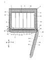
- FIG. 2 is a view when a cross section of the cryogenic freezer along the line II-II ′ in FIG. 1 is viewed from above.
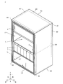
- FIG. 2 is a perspective view of the housing of FIG. 1 when an outer door and a plurality of inner doors are removed.
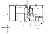
- FIG. 4 is a perspective view of a cross section of the ultra-low temperature freezer (when the outer door is opened) taken along line IV-IV ′ in FIG. 3 when viewed obliquely from above.
- FIG. 4 is a perspective view of a cross section of the ultra-low temperature freezer (when the outer door is closed) taken along line IV-IV ′ in FIG. 3 when viewed obliquely from above.
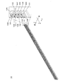
- It is a perspective view which shows the linear seal member immediately after extrusion molding. It is sectional drawing which shows the modification of a sealing member.
- the ultra-low temperature freezer 1 according to an embodiment of the present disclosure will be described in detail with reference to the drawings.
- the x-axis indicates the lateral direction of the ultra-low temperature freezer 1, more specifically, the direction from the left to the right when the user faces the ultra-low temperature freezer 1.
- the y-axis indicates the front-rear direction of the ultra-low temperature freezer 1, and more specifically indicates the direction from the back side toward the front side (ie, the front direction) at the time of facing up.
- the z-axis indicates the vertical direction of the ultra-low temperature freezer 1, and more specifically indicates the direction (that is, the vertical upward direction) directed vertically upward from the installation surface (substantially horizontal plane) of the ultra-low temperature freezer 1.
- the ultra-low temperature freezer 1 basically includes a housing 2, an outer door 3, and a machine room 4.
- the structure which cannot be visually recognized from the outside like the below-mentioned heat insulating materials 23 and 33 is shown with the broken line.
- the housing 2 generally includes, for example, a metal exterior body 21 and an interior body 22, and a plurality of heat insulating materials 23.
- the exterior body 21 defines the outer shape of the housing 2.
- the interior body 22 is provided inside the exterior body 21 and defines a space (hereinafter referred to as an accommodation space) A for accommodating a storage object.
- the front end (hereinafter referred to as opening A1) has a substantially rectangular shape parallel to the zx plane.
- the plurality of heat insulating materials 23 are preferably made of a vacuum heat insulating panel, a polyurethane laminate, or the like. 1 and 2 do not show all the heat insulating materials 23 for convenience. More specifically, in FIG.
- FIG. 1 shows heat insulating materials 23 interposed between the right side surface of the exterior body 21 and the right side surface of the interior body 22, and between the upper surface of the exterior body 21 and the upper surface of the interior body 22. Only one heat insulating material 23 interposed between the two is indicated by a broken line.
- FIG. 2 shows heat insulating materials 23 provided on the left and right sides and the back surface of the housing 2.
- the vacuum insulation panel of the heat insulating material 23 is shown with a left-down hatching, and polyurethane is shown with a right-down hatching.
- the outer door 3 includes, for example, a metal interior body 31 and an exterior body 32, and at least one heat insulating material 33 disposed in a space between the interior body 31 and the exterior body 32.
- the outer door 3 is rotated around the rotation axis of the three hinges 34, for example, and opened and closed by a user operation.
- the outer door 3 closes the opening A1 when closed.
- the user can open and close the inner door 5 described later.
- the heat insulating material 33 is preferably made of a combination of a vacuum heat insulating panel and polyurethane similar to the heat insulating material 23. In FIG. 1, one heat insulating material 33 is illustrated by a broken line. In FIG.
- a vacuum heat insulating panel constituting one heat insulating material 33 is provided on the inner surface S ⁇ b> 10 side of the outer door 3 (see the left-down hatching), and polyurethane is formed between the vacuum heat insulating panel and the exterior body 32. In between (see right-down hatching).
- the outer door 3 is provided with a handle 35 that a user grips when opening and closing.
- the handle 35 has a lock mechanism 36 in this embodiment.
- the lock mechanism 36 locks the outer door 3 in a closed state or releases the locked state so that the outer door 3 can be opened. Since the outer door 3 is locked by the lock mechanism 36, the airtightness and heat insulation of the ultra-low temperature freezer 1 can be increased.
- a control panel 37 is provided on the outer surface of the outer door 3.
- the control panel 37 includes a control circuit board (not shown) inside and a touch panel that can be operated and visually recognized by the user.
- the touch panel is a device that allows the user to set the target temperature (that is, the target value of the internal temperature) of the storage space A, and various information such as the current set temperature (target value of the internal temperature). Is a device that displays.
- the machine room 4 is provided in the lower part of the housing
- the machine room 4 stores a well-known binary refrigeration cycle (also called a cascade cycle).
- a well-known binary refrigeration cycle also called a cascade cycle.
- the low temperature side evaporator is disposed between the exterior body 21 and the interior body 22 of the housing 2 so as to surround the accommodation space A.
- the cascade capacitor is arranged on the back side of the accommodation space A.
- the remaining elements are stored in the machine room 4. Note that details of the dual refrigeration cycle are described in detail in JP 2010-096490 A and the like, and thus detailed description in this embodiment is omitted.
- two unit multi-stage refrigeration cycles that are controlled independently of each other may be provided inside the machine room 4.
- an evaporator provided in each unit multi-stage refrigeration cycle is arranged inside the housing 2 so as to surround the accommodation space A. Even if a problem occurs in one unit multi-stage refrigeration cycle, the inside of the storage space A is maintained in an ultra-low temperature region by the other unit multi-stage refrigeration cycle.
- the ultra-low temperature freezer 1 preferably further includes at least one inner door 5 and at least one storage box 6.
- Each inner door 5 is made of, for example, resin, and rotates around a rotation axis parallel to the z axis by at least one inner door side hinge (not shown) at the right end of the opening A1.
- the inner door 5 is opened and closed by a user operation.
- Each inner door 5 closes at least a part of the opening A1 when closed.
- the user can access the accommodation space A.
- Such an inner door 5 enhances the heat insulating effect in the accommodation space A.
- the storage box 6 accommodates the object to be stored and is placed on the gantry 7 provided in the accommodation space A.
- a user opens the outer door 3 and the inner door 5, and pulls out the storage box 6 from the storage space A first.
- Outer surface of housing 2 / outer door 3 >> As shown in FIGS. 2 and 3, the outer surface of the housing 2 includes a housing-side left side surface S1, a housing-side right side surface S2, a back surface S3, a housing-side peripheral edge S4, a top surface S5, and a bottom surface S6. And including.
- the left side surface S1 and the right side surface S2 are opposed to each other in the left-right direction, and are, for example, a plane substantially parallel to the yz plane.
- the right side surface S2 faces the left side surface S1 at a position separated from the left side surface S1 by about 1030 mm in the lateral direction (that is, in the x-axis direction).
- the back surface S3 and the peripheral edge portion S4 face each other in the front-rear direction and include, for example, a surface substantially parallel to the zx plane.
- the peripheral edge portion S4 is the first peripheral edge portion and faces the back surface S3 at a position separated from the back surface S3 by about 793 mm in the y-axis direction.
- the peripheral edge S4 surrounds the opening A1 from four directions (that is, up, down, left and right) along the outer edge of the opening A1.
- the top surface S5 and the bottom surface S6 face each other in the vertical direction, and include, for example, a surface substantially parallel to the xy plane.
- the top surface S5 faces the bottom surface S6 at a position about 1540 mm away from the bottom surface S6 (that is, in the x-axis direction).
- the outer surface of the outer door 3 includes a door-side left side surface S7, a door-side right side surface S8, an outer surface S9, an inner surface S10, and a door-side peripheral edge S11.
- the opened outer door 3 is also indicated by a broken line.
- the left side surface S7 and the right side surface S8 face each other in the left-right direction when the outer door 3 is closed, and include, for example, surfaces substantially parallel to the yz plane.
- the right side surface S8 faces the left side surface S7 at a position separated from the left side surface S7 by about 1030 mm in the x-axis direction.
- the left side surface S7 and the right side surface S8 are directed forward (that is, in the y-axis direction) from a left end portion and a right end portion of an inner surface S10 described later.
- the length in the y-axis direction of the left side surface S7 and the right side surface S8 is, for example, about 60 mm.
- the outer surface S9 and the inner surface S10 face each other in the front-rear direction when the outer door 3 is closed.
- the inner surface S10 closes the opening A1 when the outer door 3 is closed.
- the outer surface S9 is separated from the inner surface S10 by about 90 mm at the maximum in the forward direction (that is, the y-axis direction).
- the door side peripheral edge portion S11 is a second peripheral edge portion, forms an outer edge portion of the inner surface S10, and includes a surface substantially parallel to the zx plane when the outer door 3 is closed. Further, when the outer door 3 is closed, the peripheral edge portion S11 opposes the peripheral edge portion S4 and the y-axis direction as an example of the first direction via a seal member 10 described later.
- FIG. 4A is an enlarged view of the cross section of the front left end portion of the ultra-low temperature freezer 1 (when the outer door 3 is opened) along the line IV-IV ′ of FIG.
- FIG. 4B is an enlarged view of the cross section of the front left end portion of the ultra-low temperature freezer 1 (when the outer door 3 is closed) along the line IV-IV ′ of FIG.
- FIG. 5 is a perspective view showing the linear seal member 10 immediately after extrusion molding.
- a resin-made case-side breaker 8 and a door-side breaker 9 are preferably attached to the case-side peripheral portion S4 and the door-side peripheral portion S11.
- the case-side breaker 8 is provided on the peripheral edge S4 so as to surround the opening A1 in a plan view from the y-axis direction regardless of whether the outer door 3 is opened or closed.
- the door-side breaker 9 is provided on the peripheral edge S11 so as to surround the opening A1 in a plan view from the y-axis direction when the outer door 3 is closed.
- the sealing member 10 is attached on the peripheral edge S4 through the above-described case-side breaker 8 so as to surround the opening A1 in a plan view from the y-axis direction (see FIG. 3).
- the seal member 10 is typically manufactured by processing an elastic material such as rubber or resin by extrusion and then bending it so as to match the shape of the peripheral edge S4.
- the sealing member 10 includes a base 101, a mounting part 102, a first air layer forming part 103, a second air layer forming part 104, a third air layer forming part 105, a first connecting part 106, and a second
- the connecting portion 107 and a plurality of ribs 108 are included. Further, it is preferable that the seal member 10 is manufactured by integral molding, and each of the portions 101 to 107 has an integral structure.
- the base material 101 has a rectangular frame shape in plan view from the y-axis direction, and has a predetermined thickness in the y-axis direction. Moreover, the base material 101 is provided on the housing-side breaker 8 so as to extend along the periphery of the opening A1 in a plan view from the y-axis direction.
- the direction in which the base material 101 extends is referred to as the extending direction p.
- the extending direction p is a direction parallel to each side of the rectangular opening A1, as shown in FIG. That is, the extending direction p is a direction parallel to the x axis or the z axis.
- the mounting portion 102 projects rearward from the back surface of the base material 101 (that is, the negative direction side of the base material 101 in the y-axis).
- the attachment portion 102 is inserted into a slit 81 formed in the housing-side breaker 8, whereby the seal member 10 is attached to the housing-side breaker 8.
- Each of the air layer forming portions 103 to 105 is hollow, protrudes forward from the front surface of the base material 101 (that is, the positive direction side of the y-axis), and extends in all directions around the opening A1 (that is, up, down, left, and right) ).
- the air layer forming units 104 and 105 are aligned with the air layer forming units 103 and 104 at a predetermined interval in the second direction q.
- the second direction q is a direction orthogonal to the extending direction p and the y-axis direction (that is, the first direction).
- the air layer forming units 103 to 105 are arranged along the x-axis direction (that is, the lateral direction).
- the air layer forming portions 103 to 105 are arranged along the z-axis direction (that is, the vertical direction).
- the air layer forming portions 103 to 105 have an elliptical shape when the outer door 3 is opened and when cut along a virtual plane including the line IV-IV ′ as shown in FIG. 4A. It has an inner peripheral surface and an outer peripheral surface forming an elliptical arc.
- the virtual plane is a plane orthogonal to the extending direction p and parallel to the y-axis.
- the ellipses forming the cross-sectional shape of each inner peripheral surface have the same curvature distribution.
- elliptical arcs defining the cross-sectional shape of each outer peripheral surface have the same curvature distribution.
- the first connecting portion 106 has both outer peripheral surfaces so as to surround the entire periphery of the opening A1 from four directions and to be spanned between the outer peripheral surfaces of the air layer forming portions 103 and 104 in a plan view from the y-axis direction.
- the first connecting part 106 has substantially the same shape as the end part in the y-axis direction of the second air layer forming part 104. More specifically, the inner peripheral surface and the outer peripheral surface of the first connecting portion 106 are shaped like a virtual translation of the inner peripheral surface and the outer peripheral surface of the second air layer forming portion 104 in the y-axis direction ends. Have As a result, the inner peripheral surface of the first connecting portion 106 forms an air layer together with the outer peripheral surfaces of the air layer forming portions 103 and 104 and the surface of the base material 101.
- the second connecting portion 107 has both outer peripheral surfaces so as to surround the entire periphery of the opening A1 from four directions and to be spanned between the outer peripheral surfaces of the air layer forming portions 104 and 105 in a plan view from the y-axis direction. Connect.
- the inner peripheral surface of the second connection portion 107 forms an air layer together with the outer peripheral surfaces of both the air layer forming portions 104 and 105 and the surface of the base material 101, similarly to the first connection portion 106.
- the end A of the seal member 10 surrounds the opening A1 from four sides when the outer door 3 is closed.
- a total of four concave portions C1 to C4 that is, the first concave portion C1 to the fourth concave portion C4) are formed.
- a plurality of ribs 108 projecting in the y-axis direction are formed on the outer peripheral surfaces of the air layer forming portions 103 to 105 and the connecting portions 106 and 107 having the above-described configuration.
- the seal member 10 is formed with four recesses C1 to C4 at the end in the y-axis direction. Therefore, when the outer door 3 is closed, moisture remaining between the end portion in the y-axis direction of the seal member 10 and the door-side breaker 9 is divided by the recesses C1 to C4. Therefore, even if they are frozen due to moisture between the end of the seal member 10 in the y-axis direction and the door-side breaker 9, there is no contact with the door-side breaker 9 per piece of ice divided by the recesses C1 to C4. Since the contact area is reduced, it is possible to reduce the difficulty of opening the outer door 3.
- the recesses C1 to C4 are separated from each other so that the outer peripheral surfaces of the seal members 10 forming the recesses C1 to C4 widen the openings of the recesses C1 to C4. Therefore, the depths of the recesses C1 to C4 are shallow.
- the outer peripheral surfaces approach each other so as to narrow the openings of the recesses C1 to C4, and the depth of each recess C1 to C4 increases. Deepen.
- the ice frozen in the recesses C1 to C4 when the outer door 3 is closed is pushed out of the recesses C1 to C4 when the outer door 3 is opened, and remains in the recesses C1 to C4. This can be reduced. Thereby, it can reduce that the outer door 3 becomes difficult to open. Further, it is possible to reduce the burden of cleaning the concave portions C1 to C4 by the user.
- At least one rib 108 is provided on the outer peripheral surfaces of the air layer forming portions 103 to 105 and the connecting portions 106 and 107.
- the contact area with the door-side breaker 9 per piece of divided ice is reduced, so that moisture between the y-axis direction end of the seal member 10 and the door-side breaker 9 Even if these freeze, it is possible to further reduce the difficulty of opening the outer door 3.
- the connecting portion 106 connects two adjacent air layer forming portions 103 and 104 at a position separated from the surface of the base material 101.
- the connection unit 107 is the same. Therefore, the depths of the recesses C1 to C4 are relatively shallow, and the user can easily clean the recesses C1 to C4.
- the connecting portions 106 and 107 are not provided, the space between the air layer forming portions 103 to 105 must be cleaned, and the user is forced to perform time-consuming cleaning.
- an air layer is added by the connecting portions 106 and 107 in addition to the air layer in the air layer forming portions 103 to 105. Accordingly, since a total of five air layers are arranged in the second direction q, it is possible to improve the airtightness and heat insulation of the ultra-low temperature freezer 1.
- each of the air layer forming portions 103 to 105 has a structure that tends to collapse toward the base material 101 when a load from the y-axis direction is applied.
- the curvature distributions of the outer peripheral surfaces are equal to each other, and the curvature distributions of the inner peripheral surfaces are also equal to each other. Furthermore, the curvature distribution of the outer peripheral surface and the inner peripheral surface of the connecting portions 106 and 107 is also equal to the curvature distribution of the outer peripheral surface and the inner peripheral surface of the air layer forming unit 103 and the like. Furthermore, the interval between the adjacent air layer forming units 103 and 104 and the interval between the adjacent air layer forming units 104 and 105 are equal to each other.
- the cross-sectional shapes of the air layer forming portions 103 to 105 are substantially elliptical shapes, and the cross-sectional shapes of the connecting portions 106 and 107 are elliptical arc shapes.
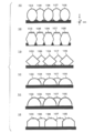
- the present invention is not limited to this, and as shown in the uppermost part of FIG. 6, the cross-sectional shape of each of the air layer forming portions 103 and 104 may be a perfect circle.
- the cross-sectional shape of the connecting portion 106 may have a shape that is obtained by virtually translating the end portions in the y-axis direction of the perfect air layer forming portions 103 and 104 in the second direction q.
- the cross-sectional shapes of the air layer forming portions 103 to 105 may be hexagonal or pentagonal.
- the cross-sectional shape of each connecting portion 106, 107 may have a shape obtained by translating the end portions in the y-axis direction of hexagonal or pentagonal air layer forming portions 103-105 in the x-axis direction.
- the cross-sectional shapes of the air layer forming portions 103 to 105 may be semicircular or semielliptical.
- the cross-sectional shape of each connecting portion 106, 107 has such a shape that the end portions in the y-axis direction of the semicircular and semi-elliptical air layer forming portions 103-105 are translated in the x-axis direction. It does not matter.
- each of the air layer forming portions 103 to 105 may be a half octagonal shape.
- the cross-sectional shape of each connecting portion 106, 107 has such a shape that the y-axis direction end portions of the half-octagon air layer forming portions 103-105 are translated in the x-axis direction.
- both sides extending from the bending points on the inner peripheral surface and the outer peripheral surface are not necessarily non-parallel to the y-axis.
- the sides of are non-parallel.
- the air layer forming portions 103 to 105 are liable to be crushed toward the base material 101 when a load from the y-axis direction is applied.
- the seal member 10 is provided on the peripheral edge S4 on the housing 2 side.
- the present invention is not limited to this, and the seal member 10 may be provided on the peripheral edge S11 on the outer door 3 side.
- the seal member 10 has been described as including three air layer forming portions 103 to 105 and two connecting portions 106 and 107.
- the present invention is not limited to this, and the seal member 10 only needs to include at least two air layer forming portions and at least one connection portion.
- the plurality of ribs 108 is not an essential configuration and may be provided as necessary.
- the ultra-low temperature freezer according to the present invention can reduce the difficulty of opening the outer door due to freezing, and is suitable for applications related to biomedicine and the like.
Landscapes
- Engineering & Computer Science (AREA)
- Chemical & Material Sciences (AREA)
- Combustion & Propulsion (AREA)
- Physics & Mathematics (AREA)
- Mechanical Engineering (AREA)
- Thermal Sciences (AREA)
- General Engineering & Computer Science (AREA)
- Refrigerator Housings (AREA)
- Cold Air Circulating Systems And Constructional Details In Refrigerators (AREA)
Abstract
Description
以下、上記図面を参照して、本開示の一実施形態に係る超低温フリーザ1について詳説する。
≪1-1.定義≫
各図において、x軸は、超低温フリーザ1の横方向を示し、より具体的には、ユーザが超低温フリーザ1と正対した時に左側から右側に向かう方向を示す。y軸は、超低温フリーザ1の前後方向を示し、より具体的には、上記正対時に奥側から手前側に向かう方向(即ち、前方向)を示す。また、z軸は、超低温フリーザ1の上下方向を示し、より具体的は、超低温フリーザ1の設置面(略水平面)から鉛直上方に向かう方向(即ち、鉛直上方向)を示す。
超低温フリーザ1は、図1~図3に示すよう、基本的には、筐体2と、外扉3と、機械室4と、を備えている。なお、図1では、後述の断熱材23,33のように外部から視認出来ない構成を破線で示している。
筐体2の外表面は、図2,図3に示すように、筐体側左側面S1と、筐体側右側面S2と、背面S3と、筐体側周縁部S4と、天面S5と、底面S6と、を含む。
図4Aは、図3の線IV-IV’に沿う超低温フリーザ1(外扉3を開けた時)の前方左端部分の断面を斜め上方から見た時の拡大図である。図4Bは、図3の線IV-IV’に沿う超低温フリーザ1(外扉3を閉じた時)の前方左端部分の断面を斜め上方から見た時の拡大図である。なお、図示が煩雑になることを避けるため、図4Bには、シール部材10の各構成の参照符号を付していない。図5は、押し出し成型直後の直線状のシール部材10を示す斜視図である。
以上の筐体側周縁部S4および扉側周縁部S11には、図4Aおよび図4Bに示すように、例えば樹脂製の筐体側ブレーカ8および扉側ブレーカ9が取り付けられることが好ましい。筐体側ブレーカ8は、外扉3の開閉に関わらず、y軸方向からの平面視で開口A1を取り囲むように周縁部S4上に設けられる。それに対し、扉側ブレーカ9は、外扉3が閉じた時に、y軸方向からの平面視で開口A1を取り囲むように、周縁部S11上に設けられる。
ユーザは、外扉3を閉じる時、図4Bに示すように、外扉3を筐体2に押し付けた状態で、ロック機構36を操作して、外扉3を筐体2に対し固定する。その結果、扉側周縁部S11がシール部材10を介して筐体側周縁部S4と近接し前後方向に対向する。この時、シール部材10は、扉側ブレーカ9と筐体側ブレーカ8との間で押し潰され、これによって、収容スペースAの温度を超低温域に維持することに寄与する。
上記説明では、各空気層形成部103~105の断面形状は略楕円形状であり、各接続部106,107の断面形状は楕円弧形状であった。しかし、これに限らず、図6最上段に示すように、各空気層形成部103,104の断面形状は真円状であっても構わない。接続部106の断面形状は、真円状の空気層形成部103,104のy軸方向端部を第二方向qに仮想的に平行移動させたような形状を有していても構わない。
上記説明では、シール部材10は、筐体2側の周縁部S4に設けられていた。しかし、これに限らず、シール部材10は、外扉3側の周縁部S11に設けられていても構わない。
2 筐体
S4 筐体側周縁部
A1 開口
3 外扉
S11 扉側周縁部
10 シール部材
103 第一空気層形成部
104 第二空気層形成部
105 第三空気層形成部
106 第一接続部
107 第二接続部
C1 第一凹部
C2 第二凹部
108 リブ
Claims (14)
- 開口の周囲に第一周縁部を有する筐体と、
前記筐体に開閉自在に取り付けられた扉であって、閉じた時に前記第一周縁部と第一方向において対向する第二周縁部を有する扉と、
前記扉が閉じた時に前記第一および前記第二周縁部の間に介在するシール部材と、を備え、
前記シール部材は、
前記扉が閉じた時に前記第一および前記第二周縁部の間で第二方向に並ぶ中空の第一および第二空気層形成部と、
前記第一および前記第二空気層形成部の間に架け渡されて空気層を形成する第一接続部と、を有し、
前記第一接続部は、前記第二方向へと仮想的に平行移動した時に、前記第一および前記第二空気層形成部の一部と重なり合う形状を有し、
前記第一接続部の外周面と、前記第一および前記第二空気層形成部の外周面とは、前記第一方向に延在する第一および第二凹部を形成する、超低温フリーザ。 - 前記第一および前記第二空気層形成部の内周面は、前記第一方向と非平行な部分を含む、請求項1に記載の超低温フリーザ。
- 前記第一および前記第二空気層形成部の内周面は、前記第一方向から平面視した時、互いに同一の真円形状または円弧形状を有する、請求項1に記載の超低温フリーザ。
- 前記第一および前記第二空気層形成部の内周面は、前記第一方向から平面視した時、互いに同一の曲率分布を有する楕円形状または楕円弧形状を有する、請求項1に記載の超低温フリーザ。
- 前記第一および前記第二空気層形成部の内周面は、前記第一方向から平面視した時、互いに同一の多角形形状を有する、請求項1に記載の超低温フリーザ。
- 前記第一および前記第二空気層形成部の各外周面には、前記第一または前記第二周縁部向かって突出するリブが形成されている、請求項1ないし5のいずれかに記載の超低温フリーザ。
- 前記シール部材は、
前記扉が閉じた時に前記第一および前記第二周縁部の間で、前記第二空気層形成部を基準として前記第二方向に並ぶ中空の第三空気層形成部と、
前記第二空気層形成部および前記第三空気層形成部の間に架け渡されて空気層を形成する第二接続部と、をさらに有する、請求項1に記載の超低温フリーザ。 - 前記第一ないし前記第三空気層形成部の内周面は、前記第一方向と非平行な部分を含む、請求項7に記載の超低温フリーザ。
- 前記第一ないし前記第三空気層形成部の内周面は、前記第一方向から平面視した時、互いに同一の真円形状または円弧形状を有する、請求項7または8に記載の超低温フリーザ。
- 前記第一ないし前記第三空気層形成部の内周面は、前記第一方向から平面視した時、互いに同一の曲率分布を有する楕円形状または楕円弧形状を有する、請求項7または8に記載の超低温フリーザ。
- 前記第一ないし前記第三空気層形成部の内周面は、前記第一方向から平面視した時、互いに同一の多角形形状を有する、請求項7または8に記載の超低温フリーザ。
- 前記第一ないし前記第三空気層形成部の各外周面には、前記第一または前記第二周縁部向かって突出するリブが形成されている、請求項7ないし11のいずれかに記載の超低温フリーザ。
- 前記第一および前記第二空気層形成部の間の前記第二方向への空間距離は、前記第二および前記第三空気層形成部の間の前記第二方向への空間距離と同じである、請求項7ないし12のいずれかに記載の超低温フリーザ。
- 前記第二接続部は、前記第二方向へと仮想的に平行移動した時に、前記第二および前記第三空気層形成部の一部と重なり合う形状を有し、
前記第二接続部の外周面と、前記第二および第三空気層形成部の外周面とは、前記第一方向に延在する前記第二および第三凹部を形成する、請求項13に記載の超低温フリーザ。
Priority Applications (5)
| Application Number | Priority Date | Filing Date | Title |
|---|---|---|---|
| KR1020187025170A KR102196253B1 (ko) | 2016-03-11 | 2017-03-02 | 초저온 프리저 |
| JP2018504423A JP6603397B2 (ja) | 2016-03-11 | 2017-03-02 | 超低温フリーザ |
| CN201780015624.2A CN108700364B (zh) | 2016-03-11 | 2017-03-02 | 超低温冷冻机 |
| EP17763073.8A EP3428558B1 (en) | 2016-03-11 | 2017-03-02 | Ultra-low temperature freezer |
| US16/128,437 US10627155B2 (en) | 2016-03-11 | 2018-09-11 | Ultra-low temperature freezer |
Applications Claiming Priority (2)
| Application Number | Priority Date | Filing Date | Title |
|---|---|---|---|
| JP2016-048222 | 2016-03-11 | ||
| JP2016048222 | 2016-03-11 |
Related Child Applications (1)
| Application Number | Title | Priority Date | Filing Date |
|---|---|---|---|
| US16/128,437 Continuation US10627155B2 (en) | 2016-03-11 | 2018-09-11 | Ultra-low temperature freezer |
Publications (1)
| Publication Number | Publication Date |
|---|---|
| WO2017154733A1 true WO2017154733A1 (ja) | 2017-09-14 |
Family
ID=59789254
Family Applications (1)
| Application Number | Title | Priority Date | Filing Date |
|---|---|---|---|
| PCT/JP2017/008316 Ceased WO2017154733A1 (ja) | 2016-03-11 | 2017-03-02 | 超低温フリーザ |
Country Status (6)
| Country | Link |
|---|---|
| US (1) | US10627155B2 (ja) |
| EP (1) | EP3428558B1 (ja) |
| JP (1) | JP6603397B2 (ja) |
| KR (1) | KR102196253B1 (ja) |
| CN (1) | CN108700364B (ja) |
| WO (1) | WO2017154733A1 (ja) |
Cited By (1)
| Publication number | Priority date | Publication date | Assignee | Title |
|---|---|---|---|---|
| WO2019225690A1 (ja) | 2018-05-25 | 2019-11-28 | Phcホールディングス株式会社 | 冷却装置の密閉構造及び冷却装置 |
Families Citing this family (3)
| Publication number | Priority date | Publication date | Assignee | Title |
|---|---|---|---|---|
| GB201818126D0 (en) * | 2018-11-07 | 2018-12-19 | B Medical Systems Sarl | Freezers and refigerators |
| US11306967B2 (en) | 2020-02-10 | 2022-04-19 | Whirlpool Corporation | Drawer gasket seal assembly |
| USD1042297S1 (en) | 2022-07-01 | 2024-09-17 | Oxford Instruments Nanotechnology Tools Limited | Cryogenic cooling system |
Citations (10)
| Publication number | Priority date | Publication date | Assignee | Title |
|---|---|---|---|---|
| JPS4927892B1 (ja) * | 1967-02-09 | 1974-07-22 | ||
| JPS54143033U (ja) * | 1978-03-29 | 1979-10-04 | ||
| JPS5724358U (ja) * | 1980-07-17 | 1982-02-08 | ||
| JPS57100666U (ja) * | 1980-12-12 | 1982-06-21 | ||
| JPS6114190U (ja) * | 1984-06-30 | 1986-01-27 | 横浜ゴム株式会社 | 艙口蓋用パツキン |
| US5600966A (en) * | 1995-05-19 | 1997-02-11 | Forma Scientific, Inc. | Ultra low temperature split door freezer |
| JPH11311477A (ja) * | 1998-04-28 | 1999-11-09 | Hoshizaki Electric Co Ltd | 冷却貯蔵庫のドアシール構造 |
| CN2692602Y (zh) * | 2004-04-26 | 2005-04-13 | 威海安泰电子制冷设备有限公司 | 超低温双密封门 |
| JP2006046852A (ja) * | 2004-08-06 | 2006-02-16 | Hoshizaki Electric Co Ltd | 冷却貯蔵庫 |
| JP5671675B2 (ja) * | 2010-10-28 | 2015-02-18 | パナソニックヘルスケアホールディングス株式会社 | 栓部材、低温貯蔵庫 |
Family Cites Families (19)
| Publication number | Priority date | Publication date | Assignee | Title |
|---|---|---|---|---|
| US1883609A (en) * | 1930-05-31 | 1932-10-18 | William J Dennis | Gasket |
| US2908949A (en) * | 1957-11-12 | 1959-10-20 | Gen Tire & Rubber Co | Honeycomb plastic door gasket |
| US2968845A (en) * | 1958-05-09 | 1961-01-24 | Foster Refrigerator Corp | Refrigerator door construction |
| US3078134A (en) * | 1961-06-12 | 1963-02-19 | Gen Motors Corp | Refrigerator door sealing |
| US3178778A (en) * | 1961-10-10 | 1965-04-20 | H O Canfield Company Inc | Refrigerator seal |
| JPS5553907Y2 (ja) * | 1975-08-27 | 1980-12-13 | ||
| US4138049A (en) * | 1976-10-29 | 1979-02-06 | The Pantasote Company | Dual function sealing gasket |
| FR2445916A1 (fr) * | 1979-01-04 | 1980-08-01 | Refrigeration Cie Caladoise | Appareil de production de froid, muni d'un systeme de reequilibrage de pressions |
| US4462646A (en) * | 1982-09-29 | 1984-07-31 | Whirlpool Corporation | Insulated cabinet construction for chest freezers |
| US4826010A (en) * | 1987-07-31 | 1989-05-02 | White Consolidated Industries, Inc. | Refrigeration cabinet construction |
| CN1045641A (zh) * | 1989-03-12 | 1990-09-26 | 郭军 | 凹凸型冷藏恒温箱门封 |
| US5289657A (en) * | 1992-03-13 | 1994-03-01 | The Standard Products Company | Refrigerator gasket and retainer |
| JP3018297U (ja) * | 1995-05-18 | 1995-11-14 | 株式会社タック | 目地シール材 |
| JP2005147476A (ja) | 2003-11-13 | 2005-06-09 | Hoshizaki Electric Co Ltd | 貯蔵庫 |
| US7823331B2 (en) * | 2005-11-16 | 2010-11-02 | Holm Industries, Inc. | French door seal having a magnetic pair |
| JP5313093B2 (ja) | 2008-09-16 | 2013-10-09 | パナソニックヘルスケア株式会社 | 冷凍装置 |
| WO2011142128A1 (ja) * | 2010-05-11 | 2011-11-17 | パナソニック株式会社 | 冷蔵庫 |
| BRPI1101701A2 (pt) * | 2011-04-18 | 2013-06-11 | Whirlpool Sa | sistema de vedaÇço para refrigerador |
| PT3006869T (pt) * | 2013-06-08 | 2018-08-08 | Hefei Midea Refrigerator Co | Dispositivo de refrigeração |
-
2017
- 2017-03-02 WO PCT/JP2017/008316 patent/WO2017154733A1/ja not_active Ceased
- 2017-03-02 CN CN201780015624.2A patent/CN108700364B/zh active Active
- 2017-03-02 KR KR1020187025170A patent/KR102196253B1/ko active Active
- 2017-03-02 JP JP2018504423A patent/JP6603397B2/ja active Active
- 2017-03-02 EP EP17763073.8A patent/EP3428558B1/en active Active
-
2018
- 2018-09-11 US US16/128,437 patent/US10627155B2/en active Active
Patent Citations (10)
| Publication number | Priority date | Publication date | Assignee | Title |
|---|---|---|---|---|
| JPS4927892B1 (ja) * | 1967-02-09 | 1974-07-22 | ||
| JPS54143033U (ja) * | 1978-03-29 | 1979-10-04 | ||
| JPS5724358U (ja) * | 1980-07-17 | 1982-02-08 | ||
| JPS57100666U (ja) * | 1980-12-12 | 1982-06-21 | ||
| JPS6114190U (ja) * | 1984-06-30 | 1986-01-27 | 横浜ゴム株式会社 | 艙口蓋用パツキン |
| US5600966A (en) * | 1995-05-19 | 1997-02-11 | Forma Scientific, Inc. | Ultra low temperature split door freezer |
| JPH11311477A (ja) * | 1998-04-28 | 1999-11-09 | Hoshizaki Electric Co Ltd | 冷却貯蔵庫のドアシール構造 |
| CN2692602Y (zh) * | 2004-04-26 | 2005-04-13 | 威海安泰电子制冷设备有限公司 | 超低温双密封门 |
| JP2006046852A (ja) * | 2004-08-06 | 2006-02-16 | Hoshizaki Electric Co Ltd | 冷却貯蔵庫 |
| JP5671675B2 (ja) * | 2010-10-28 | 2015-02-18 | パナソニックヘルスケアホールディングス株式会社 | 栓部材、低温貯蔵庫 |
Cited By (3)
| Publication number | Priority date | Publication date | Assignee | Title |
|---|---|---|---|---|
| WO2019225690A1 (ja) | 2018-05-25 | 2019-11-28 | Phcホールディングス株式会社 | 冷却装置の密閉構造及び冷却装置 |
| CN112189122A (zh) * | 2018-05-25 | 2021-01-05 | 普和希控股公司 | 冷却装置的密闭结构及冷却装置 |
| EP3783285A4 (en) * | 2018-05-25 | 2021-06-23 | PHC Holdings Corporation | Sealing structure for cooling device and cooling device |
Also Published As
| Publication number | Publication date |
|---|---|
| EP3428558B1 (en) | 2020-02-12 |
| US10627155B2 (en) | 2020-04-21 |
| EP3428558A4 (en) | 2019-03-27 |
| EP3428558A1 (en) | 2019-01-16 |
| CN108700364B (zh) | 2020-07-03 |
| CN108700364A (zh) | 2018-10-23 |
| JPWO2017154733A1 (ja) | 2018-10-04 |
| KR102196253B1 (ko) | 2020-12-29 |
| KR20180108770A (ko) | 2018-10-04 |
| JP6603397B2 (ja) | 2019-11-06 |
| US20190011176A1 (en) | 2019-01-10 |
Similar Documents
| Publication | Publication Date | Title |
|---|---|---|
| JP6603397B2 (ja) | 超低温フリーザ | |
| JP6564126B2 (ja) | 超低温フリーザ | |
| EP3006869B1 (en) | Refrigeration device | |
| CN102235784A (zh) | 冰箱及其门把手和门 | |
| CN108253708A (zh) | 家用电器 | |
| CN110177984A (zh) | 冰箱 | |
| CN104034117B (zh) | 保冷箱 | |
| WO2016113907A1 (ja) | 冷蔵庫 | |
| WO2017175402A1 (ja) | 冷却貯蔵庫の扉装置 | |
| US12305910B2 (en) | Refrigeration apparatus | |
| US11333428B2 (en) | Heat insulating structure for cooling device, and cooling device | |
| JP2018119696A (ja) | センターシールの取付構造 | |
| CN112856904B (zh) | 冰箱门及冰箱 | |
| JP2025064679A (ja) | 貯蔵庫 | |
| CN119879486A (zh) | 用于冷柜的门体及冷柜 | |
| JP2022166699A (ja) | 冷蔵庫 | |
| JP2019113202A (ja) | 冷蔵庫 | |
| WO2018037526A1 (ja) | 冷却貯蔵庫の扉装置 |
Legal Events
| Date | Code | Title | Description |
|---|---|---|---|
| ENP | Entry into the national phase |
Ref document number: 2018504423 Country of ref document: JP Kind code of ref document: A |
|
| ENP | Entry into the national phase |
Ref document number: 20187025170 Country of ref document: KR Kind code of ref document: A |
|
| NENP | Non-entry into the national phase |
Ref country code: DE |
|
| WWE | Wipo information: entry into national phase |
Ref document number: 2017763073 Country of ref document: EP |
|
| ENP | Entry into the national phase |
Ref document number: 2017763073 Country of ref document: EP Effective date: 20181011 |
|
| 121 | Ep: the epo has been informed by wipo that ep was designated in this application |
Ref document number: 17763073 Country of ref document: EP Kind code of ref document: A1 |