WO2017154858A1 - 無線通信装置 - Google Patents
無線通信装置 Download PDFInfo
- Publication number
- WO2017154858A1 WO2017154858A1 PCT/JP2017/008879 JP2017008879W WO2017154858A1 WO 2017154858 A1 WO2017154858 A1 WO 2017154858A1 JP 2017008879 W JP2017008879 W JP 2017008879W WO 2017154858 A1 WO2017154858 A1 WO 2017154858A1
- Authority
- WO
- WIPO (PCT)
- Prior art keywords
- transmission
- dmg
- pseudo
- sta
- omni
- Prior art date
- Legal status (The legal status is an assumption and is not a legal conclusion. Google has not performed a legal analysis and makes no representation as to the accuracy of the status listed.)
- Ceased
Links
Images


Classifications
-
- H—ELECTRICITY
- H04—ELECTRIC COMMUNICATION TECHNIQUE
- H04B—TRANSMISSION
- H04B7/00—Radio transmission systems, i.e. using radiation field
- H04B7/02—Diversity systems; Multi-antenna system, i.e. transmission or reception using multiple antennas
- H04B7/04—Diversity systems; Multi-antenna system, i.e. transmission or reception using multiple antennas using two or more spaced independent antennas
- H04B7/06—Diversity systems; Multi-antenna system, i.e. transmission or reception using multiple antennas using two or more spaced independent antennas at the transmitting station
- H04B7/0613—Diversity systems; Multi-antenna system, i.e. transmission or reception using multiple antennas using two or more spaced independent antennas at the transmitting station using simultaneous transmission
- H04B7/0615—Diversity systems; Multi-antenna system, i.e. transmission or reception using multiple antennas using two or more spaced independent antennas at the transmitting station using simultaneous transmission of weighted versions of same signal
- H04B7/0617—Diversity systems; Multi-antenna system, i.e. transmission or reception using multiple antennas using two or more spaced independent antennas at the transmitting station using simultaneous transmission of weighted versions of same signal for beam forming
-
- H—ELECTRICITY
- H04—ELECTRIC COMMUNICATION TECHNIQUE
- H04W—WIRELESS COMMUNICATION NETWORKS
- H04W8/00—Network data management
- H04W8/005—Discovery of network devices, e.g. terminals
-
- H—ELECTRICITY
- H04—ELECTRIC COMMUNICATION TECHNIQUE
- H04B—TRANSMISSION
- H04B7/00—Radio transmission systems, i.e. using radiation field
- H04B7/02—Diversity systems; Multi-antenna system, i.e. transmission or reception using multiple antennas
- H04B7/04—Diversity systems; Multi-antenna system, i.e. transmission or reception using multiple antennas using two or more spaced independent antennas
- H04B7/08—Diversity systems; Multi-antenna system, i.e. transmission or reception using multiple antennas using two or more spaced independent antennas at the receiving station
- H04B7/0868—Hybrid systems, i.e. switching and combining
- H04B7/088—Hybrid systems, i.e. switching and combining using beam selection
-
- H—ELECTRICITY
- H04—ELECTRIC COMMUNICATION TECHNIQUE
- H04B—TRANSMISSION
- H04B7/00—Radio transmission systems, i.e. using radiation field
- H04B7/02—Diversity systems; Multi-antenna system, i.e. transmission or reception using multiple antennas
- H04B7/04—Diversity systems; Multi-antenna system, i.e. transmission or reception using multiple antennas using two or more spaced independent antennas
- H04B7/0491—Diversity systems; Multi-antenna system, i.e. transmission or reception using multiple antennas using two or more spaced independent antennas using two or more sectors, i.e. sector diversity
-
- H—ELECTRICITY
- H04—ELECTRIC COMMUNICATION TECHNIQUE
- H04B—TRANSMISSION
- H04B7/00—Radio transmission systems, i.e. using radiation field
- H04B7/02—Diversity systems; Multi-antenna system, i.e. transmission or reception using multiple antennas
- H04B7/04—Diversity systems; Multi-antenna system, i.e. transmission or reception using multiple antennas using two or more spaced independent antennas
- H04B7/06—Diversity systems; Multi-antenna system, i.e. transmission or reception using multiple antennas using two or more spaced independent antennas at the transmitting station
- H04B7/0686—Hybrid systems, i.e. switching and simultaneous transmission
- H04B7/0695—Hybrid systems, i.e. switching and simultaneous transmission using beam selection
- H04B7/06952—Selecting one or more beams from a plurality of beams, e.g. beam training, management or sweeping
-
- H—ELECTRICITY
- H04—ELECTRIC COMMUNICATION TECHNIQUE
- H04B—TRANSMISSION
- H04B7/00—Radio transmission systems, i.e. using radiation field
- H04B7/02—Diversity systems; Multi-antenna system, i.e. transmission or reception using multiple antennas
- H04B7/04—Diversity systems; Multi-antenna system, i.e. transmission or reception using multiple antennas using two or more spaced independent antennas
- H04B7/08—Diversity systems; Multi-antenna system, i.e. transmission or reception using multiple antennas using two or more spaced independent antennas at the receiving station
- H04B7/0837—Diversity systems; Multi-antenna system, i.e. transmission or reception using multiple antennas using two or more spaced independent antennas at the receiving station using pre-detection combining
- H04B7/0842—Weighted combining
- H04B7/086—Weighted combining using weights depending on external parameters, e.g. direction of arrival [DOA], predetermined weights or beamforming
-
- H—ELECTRICITY
- H04—ELECTRIC COMMUNICATION TECHNIQUE
- H04L—TRANSMISSION OF DIGITAL INFORMATION, e.g. TELEGRAPHIC COMMUNICATION
- H04L1/00—Arrangements for detecting or preventing errors in the information received
- H04L1/12—Arrangements for detecting or preventing errors in the information received by using return channel
- H04L1/16—Arrangements for detecting or preventing errors in the information received by using return channel in which the return channel carries supervisory signals, e.g. repetition request signals
- H04L1/1607—Details of the supervisory signal
- H04L1/1657—Implicit acknowledgement of correct or incorrect reception, e.g. with a moving window
-
- H—ELECTRICITY
- H04—ELECTRIC COMMUNICATION TECHNIQUE
- H04W—WIRELESS COMMUNICATION NETWORKS
- H04W48/00—Access restriction; Network selection; Access point selection
- H04W48/08—Access restriction or access information delivery, e.g. discovery data delivery
-
- H—ELECTRICITY
- H04—ELECTRIC COMMUNICATION TECHNIQUE
- H04W—WIRELESS COMMUNICATION NETWORKS
- H04W48/00—Access restriction; Network selection; Access point selection
- H04W48/08—Access restriction or access information delivery, e.g. discovery data delivery
- H04W48/14—Access restriction or access information delivery, e.g. discovery data delivery using user query or user detection
-
- H—ELECTRICITY
- H04—ELECTRIC COMMUNICATION TECHNIQUE
- H04W—WIRELESS COMMUNICATION NETWORKS
- H04W16/00—Network planning, e.g. coverage or traffic planning tools; Network deployment, e.g. resource partitioning or cells structures
- H04W16/24—Cell structures
- H04W16/28—Cell structures using beam steering
-
- H—ELECTRICITY
- H04—ELECTRIC COMMUNICATION TECHNIQUE
- H04W—WIRELESS COMMUNICATION NETWORKS
- H04W48/00—Access restriction; Network selection; Access point selection
- H04W48/16—Discovering, processing access restriction or access information
-
- H—ELECTRICITY
- H04—ELECTRIC COMMUNICATION TECHNIQUE
- H04W—WIRELESS COMMUNICATION NETWORKS
- H04W84/00—Network topologies
- H04W84/02—Hierarchically pre-organised networks, e.g. paging networks, cellular networks, WLAN [Wireless Local Area Network] or WLL [Wireless Local Loop]
- H04W84/10—Small scale networks; Flat hierarchical networks
- H04W84/12—WLAN [Wireless Local Area Networks]
-
- Y—GENERAL TAGGING OF NEW TECHNOLOGICAL DEVELOPMENTS; GENERAL TAGGING OF CROSS-SECTIONAL TECHNOLOGIES SPANNING OVER SEVERAL SECTIONS OF THE IPC; TECHNICAL SUBJECTS COVERED BY FORMER USPC CROSS-REFERENCE ART COLLECTIONS [XRACs] AND DIGESTS
- Y02—TECHNOLOGIES OR APPLICATIONS FOR MITIGATION OR ADAPTATION AGAINST CLIMATE CHANGE
- Y02D—CLIMATE CHANGE MITIGATION TECHNOLOGIES IN INFORMATION AND COMMUNICATION TECHNOLOGIES [ICT], I.E. INFORMATION AND COMMUNICATION TECHNOLOGIES AIMING AT THE REDUCTION OF THEIR OWN ENERGY USE
- Y02D30/00—Reducing energy consumption in communication networks
- Y02D30/70—Reducing energy consumption in communication networks in wireless communication networks
Definitions
- the present disclosure relates to a wireless communication device.
- a wireless communication device that performs wireless communication using a millimeter wave band uses a beacon transmission interval (BTI) in a device discovery procedure using a DMG (directional multi-gigabit) beacon as follows. To do.
- BTI beacon transmission interval
- a STA station corresponding to DMG (hereinafter DMG-STA or STA) is an AP (access point) / PCP (Personal basic service set Central Point) (hereinafter DMG-AP / PCP) corresponding to DMG. , Or AP / PCP), receive the DMG beacon.
- DMG-STA station corresponding to DMG
- PCP Personal basic service set Central Point
- the DMG-STA transmits a DMG beacon in which the discovery mode field is set to 1 (hereinafter “discovery DMG beacon”) in the BTI of the DMG-STA.
- SSID Service Set IDentifier
- DMG capability some fields including fields necessary for discovery (eg, SSID (Service Set IDentifier), DMG capability) are omitted.
- a non-limiting example of the present disclosure is to provide a wireless communication device capable of realizing high-speed discovery (less than 200 msec) even when the number of STAs to be discovered increases in discovery using DMG beacons. To contribute.
- a wireless communication device includes a frame configuration unit that generates a transmission frame including a plurality of DMG beacons, and one or more first DMG beacons among the plurality of DMG beacons in the BTI. Then, the first phase adjustment is performed to perform directional transmission using one or more transmission sectors, and one or more second DMG beacons out of the plurality of DMG beacons A transmission radio unit that performs pseudo-omni transmission by performing phase adjustment.
- high-speed discovery (less than 200 msec) can be realized even when STAs that are discovery targets increase in discovery using DMG beacons.
- the figure which shows an example of the device discovery procedure using the DMG beacon by the directional transmission which concerns on this indication The figure which shows another example of the device discovery procedure using the DMG beacon by the directional transmission which concerns on this indication.
- the figure which shows another example of the device discovery procedure using the DMG beacon by the directional transmission which concerns on this indication The figure which shows the structure of AP / PCP or STA which concerns on Embodiment 1 of this indication.
- the figure which shows an example of the device discovery procedure using the DMG beacon by pseudo omni transmission which concerns on Embodiment 1 of this indication The figure which shows an example of a format of the SSW field (DMG beacon: DBcn) which concerns on Embodiment 1 of this indication.
- fast discovery (less than 200 ms) is desirable. For this reason, passive scanning is not ideal for fast discovery.
- AP / PCP increases overhead by increasing the frequency of transmission sector sweeps that include discovery information.
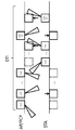
- FIG. 1 is a diagram showing an example of a device discovery procedure using a DMG beacon by directional transmission.
- FIG. 3 is a diagram showing SLS (Sector Level Sweep) in DTI.
- SLS VectorSLevel Sweep
- the STA can obtain discovery information through the SLS of FIG. 3, but it takes at least a few milliseconds.
- FIG. 2 is a diagram showing another example of a device discovery procedure using a DMG beacon by directional transmission.
- the STA predicts a response from the peer STA in the A-BFT to set the discovery mode to 1 in the BTI, but for example, when assigned, a collision with another STA occurs,
- a peer STA (AP / PCP) may have difficulty using A-BFT.
- the AP / PCP is highly likely to prioritize the operation as a base station apparatus, and may delay the beam forming by the STA.
- STAs devices
- the collision rate increases, resulting in further delay.
- the STA does not recognize the AP / PCP until the AP / PCP starts beamforming.
- the pseudo omni transmission is a beam transmitted for a part of the omni transmission, and is transmitted in a wider area than the directional transmission transmitted to one transmission sector, that is, transmitted to a plurality of transmission sectors. Means that.
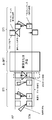
- FIG. 4 is a diagram illustrating a configuration of an AP / PCP or STA (wireless communication apparatus).
- the AP / PCP or STA includes a control unit 101, a frame signal generation unit 102, a frame configuration unit 103, a modulation unit 104, a transmission radio unit 105, a transmission antenna unit 106, a reception antenna unit 107, a reception radio unit 108, a demodulation unit 109, A frame analysis unit 110.
- the control unit 101 instructs the frame signal generation unit 102 to transmit a frame structure, controls the transmission radio unit 105 in accordance with the transmission frame, and transmits directional transmission and pseudo omnidirectional signals to the transmission antenna unit 106 and the reception antenna unit 107. Execute transmission. In addition, the control unit 101 controls the reception wireless unit 108 and the demodulation unit 109 to execute reception processing.
- the control unit 101 reports discovery information to an upper layer (not shown), and a connection command based on the report is input. Note that the connection command may be a determination in an upper layer or a determination by the user. The user's decision is input from an external input unit (not shown).
- the frame signal generation unit 102 generates a frame configuration signal used for a transmission frame in accordance with an instruction from the control unit 101.
- the frame configuration unit 103 generates a transmission frame using the frame configuration signal and data.
- the modulation unit 104 generates a modulation signal from the transmission frame, for example, using a modulation method such as QPSK, in accordance with an instruction from the control unit 101.
- the transmission radio unit 105 performs phase adjustment of the modulation signal to perform directional transmission or pseudo omni transmission from the transmission antenna unit 106 to an arbitrary transmission sector, performs frequency conversion of the modulated signal after phase adjustment, and performs radio signal conversion. Convert to
- the transmission antenna unit 106 transmits a radio signal by directional transmission or pseudo-omni transmission.
- the receiving antenna unit 107 receives a radio signal transmitted by directional transmission or pseudo omni transmission by receiving directional reception or pseudo omni reception in an arbitrary reception sector.
- the reception radio unit 108 performs frequency conversion on the received radio signal according to an instruction from the control unit 101 and converts the received radio signal into a baseband signal.
- the demodulator 109 demodulates the baseband signal and outputs a transmission frame in accordance with an instruction from the controller 101.
- the frame analysis unit 110 analyzes the frame configuration signal included in the transmission frame, and outputs discovery information (probe request, probe response, discovery DMG beacon (DBcn)) to the control unit 101.
- discovery information probe request, probe response, discovery DMG beacon (DBcn)
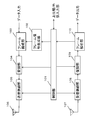
- FIG. 5 is a diagram showing an example of a device discovery procedure using a DMG beacon by pseudo omni transmission.
- STA that performs device discovery includes pseudo-omni transmission of DMG beacon in BTI.
- the DMG beacon (DBcn) indicates that the STA is used for discovery, for example by setting the discovery mode field to 1.
- One bit of each DMG beacon is used to indicate whether the BTI includes one or more pseudo omni transmissions.
- the DMG beacon transmitted by the STA pseudo omni is transmitted by the control MCS.
- the control MCS may be MCS0 defined by 11ad.
- the transmission area can be expanded to the maximum by using MSC0.
- FIG. 6 is a diagram showing an example of the format of the SSW field.
- two bits of the RXSS length field reserved in BTI are used to indicate whether the BTI includes one or more pseudo omni transmissions.
- the SSW field can also be used as a component of a DMG beacon (DMG beacon) in BTI, and can also be used as a component of an SSW frame in A-BFT.
- DMG beacon DMG beacon
- the STA transmits a pseudo omni transmission DMG beacon at least at the end of the BTI and requests a probe response (implicitly or explicitly) from the AP.
- the AP when the AP receives a DMG beacon with a plurality of directional transmissions and one or more pseudo-omni transmissions, for example, due to a collision with another device or an inconsistency with the AP schedule, -Do not complete BFT beamforming.
- a collision refers to a state that occurs when a plurality of STAs access the AP simultaneously in a limited time.
- Contradiction refers to a state that occurs when an STA that does not know the schedule performs beamforming training at an arbitrary time, in spite of the schedule (the order of STAs that transmit SLS) specified by the AP.
- the STA may receive the probe response and respond with an ACK to which the TRN-R sequence is added by directional transmission.
- the STA identifies and stores the best receiving sector from reception of the TRN-R sequence, and identifies and stores the best transmitting sector from the best receiving sector based on antenna correlation.
- the STA sends an ACK by the best transmission sector if it can be obtained in time, and sends it as a pseudo omni transmission otherwise.
- the AP receives the ACK, identifies the best receiving sector from the reception of the TRN-R sequence, and stores it. Note that the AP identifies and stores the best transmitting sector from the best receiving sector based on the correlation between the antennas.
- a probe response from the peer device can be requested by pseudo-omni transmission of the DMG beacon.
- the pseudo omni transmission of the DMG beacon can indicate that the STA is a pseudo omni transmission.
- explicit instruction information for example, setting 1 to the discovery mode
- the pseudo-omni transmission of the DMG beacon can indicate the number of pseudo-omni transmissions, or can indicate that a plurality of pseudo-omni transmissions are included in one BTI.
- the directional transmission of the DMG beacon can indicate that pseudo omni transmission is included in BTI / TXSS.
- the directional transmission of the DMG beacon can be fragmented over one or more BTIs, and the one or more BTIs may include a pseudo omni transmission of the DMG beacons.
- STA that performs device discovery can transmit a DMG beacon in BTI (see FIG. 5).
- a device uses pseudo omni transmission for one or more DMG beacons (see FIG. 5), it transmits directional transmission to all DMG beacons for A-BFT.
- Different settings length / frequency / presence / absence / others from the case of use (see FIGS. 1 and 2) can be shown.
- the device receives one or more DMG beacons transmitted by pseudo-omni transmission as part of a transmission sector sweep (TXSS) in the BTI of FIG.
- TXSS transmission sector sweep
- the device may receive a frame (eg, SLS at A-BFT completes without collision, inconsistency) before a normal beamforming exchange. , Probe response, ACK reply) can be transmitted.
- a frame eg, SLS at A-BFT completes without collision, inconsistency
- Probe response, ACK reply can be transmitted.
- the frame to be transmitted can be a pseudo omni transmission in the control MCS.
- the STA When the STA receives the directional TRN sequence in the received pseudo-omni transmission probe response, the STA can set the frame to be transmitted (ACK in DTI in FIG. 5) as directional transmission.
- the AP may add a BRP (beam definition protocol) frame for requesting / starting beam fine adjustment instead of the TRN-R sequence to the frame (probe response) to be transmitted.
- BRP beam definition protocol
- the frame to transmit can include beamforming feedback to the peer device, eg, the best transmission sector.
- a TRN sequence transmitted in a directional direction for mutual antenna training can be added to the frame to be transmitted.
- the device (STA) may avoid pseudo omni transmission to the peer device (AP), and may avoid discovery of the peer device and connection to the peer device.
- the AP can quickly find a device (STA) within the range of pseudo omni transmission by the control MCS.
- the peer device can recognize whether or not to perform discovery of the device (STA) and connection to the device (STA).
- the peer device (AP) can discover the device (STA) with minimum overhead.
- Embodiment 2 In Embodiment 1, transmission of DMG beacon by pseudo omni transmission by STA is described after transmission of DMG beacon by directional transmission in BTI. However, in Embodiment 2, transmission of DMG beacon by directional transmission is described. The addition of one or more TRN sequences by the STA will be described.
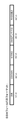
- FIG. 7 is a diagram showing another example of a device discovery procedure using a DMG beacon by pseudo omni transmission.
- a STA that performs device discovery adds one or more TRN sequences to each of the directional transmission DMG beacons in the BTI, and is pseudo-omni transmitted by the control MCS.
- the DMG beacon indicates that it is used for STA discovery, for example by setting the discovery mode field to 1, and includes a 1 ⁇ TRN (eg TRN-T) sequence appended in the PHY header .
- TRN-T may be a plurality of sequences.
- the DMG beacon implicitly or explicitly requests a probe response from the AP.
- the AP receives one or more directional transmission DMG beacons and one or more TRN-T sequences attached to each, and uses one or more TRN-T sequences in the pseudo-omni transmission. recognize.
- a beamforming training (TRN) sequence can be added to a plurality of DMG beacons transmitted in a directional manner in BTI.
- the TRN sequence can be transmitted in a fragmentation (fragmentation) over a plurality of BTIs, that is, in the BTI following the DTI.
- a DMG beacon transmitted in a directional manner to which pseudo-omni transmission of a TRN sequence is added may not explicitly indicate that pseudo-omni transmission is used for the TRN sequence.
- the STA can request a probe response from the peer device by a DMG beacon transmitted in a directional manner to which a pseudo omni transmission of a TRN sequence is added.
- the peer device can recognize whether to perform device discovery / connection with the device.
- the AP can discover a device (STA) with minimum overhead by including discovery information in the pseudo omni transmission in the BTI.
- STA device
- FIG. 8 is a diagram showing another example of a device discovery procedure using a DMG beacon by pseudo omni transmission.
- the AP includes one or more pseudo omni transmissions in the DMG beacon in the BTI.
- the DMG beacon indicates whether or not pseudo omni transmission is included in the BTI using one bit of each DMG beacon.
- the DMG beacon may indicate whether or not the frame is pseudo-omni transmission using one bit of each DMG beacon.
- the transmission sector of the pseudo omni transmission of each DMG beacon may be different for each transmission.
- the directional transmission DMG beacon transmitted after the pseudo omni transmission DMG beacon may omit the SSID, the DMG capability, and other information in order to shorten the BTI time length.
- the STA then receives a DMG beacon that is one or more pseudo omni transmissions and one or more directional transmissions, and receives the best reception from reception of a directional transmitted TRN-R sequence in the range of pseudo omni transmissions. Identify and store sectors. Note that the STA identifies and stores the best transmitting sector from the best receiving sector based on the correlation between antennas.
- the STA reports the discovery information to, for example, an upper layer or connection management software such as a supplicant, and receives a connection command to the AP / PCP from the upper layer, connection management software, or the user.
- an upper layer or connection management software such as a supplicant
- the STA connects by transmitting the association request with the TRN-R sequence added to the AP in a directional manner. Note that the STA performs pseudo-omni transmission of the TRN-R sequence.
- the AP responds to the STA request by transmitting ACK directionally in response to the association request from the STA, and then transmitting an association response.
- the STA receives the ACK and the association response for the association request, and responds with an ACK to the association response from the AP.
- TRN beam forming training
- a TRN sequence that is transmitted directionally for mutual antenna training may be added to the pseudo-omni transmission of the DMG beacon in the BTI.
- additional information used for device discovery can be included in the pseudo-omni transmission.
- the pseudo omni transmission of the DMG beacon including additional information can be transmitted at the head of the BTI.
- the legacy device can analyze the additional information.
- the device can set a frame to be transmitted as a link establishment frame (eg, association request).
- a link establishment frame eg, association request
- Peer device can recognize whether to perform device discovery / connection with device by including pseudo omni transmission in BTI.
- the peer device (AP) can discover the device (STA) with minimum overhead by including discovery information in the pseudo omni transmission of BTI.
- the peer device can omit the A-BFT by using the pseudo omni transmission and the directional TRN sequence, the beam forming time can be shortened.
- the device can prioritize discovery of the peer device / response to the peer device.
- the present disclosure has been described with respect to an example configured using hardware.
- the present disclosure can also be realized by software in cooperation with hardware.
- each functional block used in the description of each of the above embodiments is typically realized as an LSI which is an integrated circuit.
- the integrated circuit may control each functional block used in the description of the above embodiment, and may include an input and an output. These may be individually made into one chip, or may be made into one chip so as to include a part or all of them.
- the name used here is LSI, but it may also be called IC, system LSI, super LSI, or ultra LSI depending on the degree of integration.
- the method of circuit integration is not limited to LSI, and implementation using a dedicated circuit or a general-purpose processor is also possible.
- An FPGA Field Programmable Gate Array
- a Reconfigurable Processor that can reconfigure the connection or setting of circuit cells inside the LSI may be used.
- a wireless communication apparatus includes a frame configuration unit that generates a transmission frame including a plurality of DMG beacons, and one or more first DMG beacons among the plurality of DMG beacons in the BTI.
- directional transmission is performed using one or more transmission sectors by performing a first phase adjustment, and one or more second DMG beacons among the plurality of DMG beacons is
- a transmission radio unit that performs pseudo-omni transmission by performing phase adjustment of 2.
- a wireless communication device receives a probe response transmitted by pseudo omni transmission and a sequence signal used for mutual antenna training from a communication partner that transmitted the plurality of DMG beacons in DTI. And a control unit that selects, from the one or more transmission sectors, a transmission sector corresponding to the reception sector of the communication partner indicated in the sequence signal.
- the frame configuration unit generates an ack signal in response to the probe response, and the transmission radio unit directs the ack signal using the selected transmission sector. Sexual transmission.
- the present disclosure is suitable for use in a wireless communication device.
Landscapes
- Engineering & Computer Science (AREA)
- Computer Networks & Wireless Communication (AREA)
- Signal Processing (AREA)
- Computer Security & Cryptography (AREA)
- Databases & Information Systems (AREA)
- Mobile Radio Communication Systems (AREA)
- Small-Scale Networks (AREA)
Abstract
Description
図4は、AP/PCPまたはSTA(無線通信装置)の構成を示す図である。
実施の形態1では、BTIにおいて、指向性送信によるDMGビーコンの送信の後に、STAによる、疑似オムニ送信によるDMGビーコンの送信について説明したが、実施の形態2では、指向性送信によるDMGビーコンの送信のそれぞれに、STAによる1つ以上のTRNシーケンスを付加について説明する。
実施の形態3は、BTIにおいて、APによる疑似オムニ送信によるDMGビーコンの送信について説明する。
102 フレーム信号生成部
103 フレーム構成部
104 変調部
105 送信無線部
106 送信アンテナ部
107 受信アンテナ部
108 受信無線部
109 復調部
110 フレーム解析部
Claims (3)
- 複数のDMGビーコンを含む送信フレームを生成するフレーム構成部と、
BTIにおいて、
前記複数のDMGビーコンのうち、1つ以上の第1のDMGビーコンに対して、第1の位相調整を行うことによって指向性送信を1つ以上の送信セクタを用いて行い、
前記複数のDMGビーコンのうち、1つ以上の第2のDMGビーコンに対して、第2の位相調整を行うことによって疑似オムニ送信を行う、
送信無線部と、
を含む、無線通信装置。 - DTIにおいて、前記複数のDMGビーコンを送信した通信相手より、疑似オムニ送信により送信されたプローブ応答及び相互アンテナトレーニングに用いるシーケンス信号を受信する受信部と、
前記シーケンス信号に示される通信相手の受信セクタに対応する送信セクタを前記1つ以上の送信セクタから選択する制御部と、
を含む、
請求項1に記載の無線通信装置。 - 前記フレーム構成部は、前記プローブ応答に対するack信号を生成し、
前記送信無線部は、前記ack信号を前記選択した送信セクタを用いて、指向性送信を行う、
請求項2に記載の無線通信装置。
Priority Applications (18)
| Application Number | Priority Date | Filing Date | Title |
|---|---|---|---|
| CN201780013408.4A CN108702193B (zh) | 2016-03-11 | 2017-03-07 | 无线通信装置 |
| KR1020217022260A KR102316676B1 (ko) | 2016-03-11 | 2017-03-07 | 무선 통신 장치 및 통신 방법 |
| RU2018132195A RU2692230C1 (ru) | 2016-03-11 | 2017-03-07 | Устройство беспроводной связи и способ беспроводной связи |
| EP21191174.8A EP3926855A1 (en) | 2016-03-11 | 2017-03-07 | Wireless communication device |
| KR1020187026166A KR102280375B1 (ko) | 2016-03-11 | 2017-03-07 | 무선 통신 장치 및 통신 방법 |
| PL17763198T PL3429095T3 (pl) | 2016-03-11 | 2017-03-07 | Urządzenie do łączności bezprzewodowej i sposób łączności bezprzewodowej |
| ES17763198T ES2901172T3 (es) | 2016-03-11 | 2017-03-07 | Dispositivo de comunicación inalámbrica |
| CN202210236255.2A CN114513238A (zh) | 2016-03-11 | 2017-03-07 | 通信装置和通信方法 |
| MX2018010621A MX2018010621A (es) | 2016-03-11 | 2017-03-07 | Aparato de comunicacion inalambrica y metodo de comunicacion inalambrica. |
| CONC2018/0009392A CO2018009392A2 (es) | 2016-03-11 | 2017-03-07 | Aparato de comunicación inalámbrico |
| CA3017092A CA3017092C (en) | 2016-03-11 | 2017-03-07 | Wireless communication apparatus and wireless communication method |
| EP17763198.3A EP3429095B1 (en) | 2016-03-11 | 2017-03-07 | Wireless communication device |
| MYPI2018702863A MY193560A (en) | 2016-03-11 | 2017-03-07 | Wireless communication apparatus and wireless communication method |
| BR112018016904-8A BR112018016904B1 (pt) | 2016-03-11 | 2017-03-07 | Aparelho de comunicação sem fio e método de comunicação sem fio |
| US16/125,007 US10791453B2 (en) | 2016-03-11 | 2018-09-07 | Wireless communication apparatus and wireless communication method |
| US17/001,961 US11523266B2 (en) | 2016-03-11 | 2020-08-25 | Wireless communication apparatus and wireless communication method |
| US18/053,690 US12041689B2 (en) | 2016-03-11 | 2022-11-08 | Wireless communication apparatus and wireless communication method |
| US18/745,683 US20240340628A1 (en) | 2016-03-11 | 2024-06-17 | Wireless communication apparatus and wireless communication method |
Applications Claiming Priority (4)
| Application Number | Priority Date | Filing Date | Title |
|---|---|---|---|
| US201662307281P | 2016-03-11 | 2016-03-11 | |
| US62/307281 | 2016-03-11 | ||
| JP2017038599A JP7007093B2 (ja) | 2016-03-11 | 2017-03-01 | 通信装置及び通信方法 |
| JP2017-038599 | 2017-03-01 |
Related Child Applications (1)
| Application Number | Title | Priority Date | Filing Date |
|---|---|---|---|
| US16/125,007 Continuation US10791453B2 (en) | 2016-03-11 | 2018-09-07 | Wireless communication apparatus and wireless communication method |
Publications (1)
| Publication Number | Publication Date |
|---|---|
| WO2017154858A1 true WO2017154858A1 (ja) | 2017-09-14 |
Family
ID=59790480
Family Applications (1)
| Application Number | Title | Priority Date | Filing Date |
|---|---|---|---|
| PCT/JP2017/008879 Ceased WO2017154858A1 (ja) | 2016-03-11 | 2017-03-07 | 無線通信装置 |
Country Status (8)
| Country | Link |
|---|---|
| US (2) | US12041689B2 (ja) |
| JP (2) | JP7007093B2 (ja) |
| CN (2) | CN108702193B (ja) |
| ES (1) | ES2901172T3 (ja) |
| MY (1) | MY193560A (ja) |
| PL (1) | PL3429095T3 (ja) |
| RU (1) | RU2769963C2 (ja) |
| WO (1) | WO2017154858A1 (ja) |
Families Citing this family (2)
| Publication number | Priority date | Publication date | Assignee | Title |
|---|---|---|---|---|
| CN110036572B (zh) | 2016-12-28 | 2022-06-28 | 松下电器(美国)知识产权公司 | 无线终端装置及其通信方法、无线基站装置及其通信方法 |
| WO2023181919A1 (ja) | 2022-03-25 | 2023-09-28 | ソニーセミコンダクタソリューションズ株式会社 | 撮像素子および撮像素子の製造方法ならびに光検出装置 |
Citations (1)
| Publication number | Priority date | Publication date | Assignee | Title |
|---|---|---|---|---|
| JP2011514107A (ja) * | 2008-03-11 | 2011-04-28 | インテル・コーポレーション | 指向性アンテナ通信のためのビーコン及びフレーム構造 |
Family Cites Families (25)
| Publication number | Priority date | Publication date | Assignee | Title |
|---|---|---|---|---|
| KR100689508B1 (ko) * | 2003-09-04 | 2007-03-02 | 삼성전자주식회사 | 통신 시스템에서 핸드오버 수행 방법 |
| RU2286030C1 (ru) * | 2005-05-27 | 2006-10-20 | Федеральное государственное унитарное предприятие "Научно-производственное предприятие "Полет" | Вч система и способ обмена пакетными данными |
| US8089947B2 (en) * | 2007-08-31 | 2012-01-03 | Intel Corporation | Spatial reuse in directional antenna systems |
| US8856628B2 (en) | 2007-10-10 | 2014-10-07 | Qualcomm Incorporated | Method and apparatus for generation and usage of extended golay codes |
| US8239694B2 (en) * | 2008-03-31 | 2012-08-07 | Qualcomm, Incorporated | Dynamic frequency scaling of a switched mode power supply |
| US8755302B2 (en) * | 2009-09-24 | 2014-06-17 | Samsung Electronics Co., Ltd. | Method and system for ad-hoc communications over millimeter wave wireless channels in wireless systems |
| US9107221B2 (en) | 2009-09-25 | 2015-08-11 | Intel Corporation | Configurable contention-based period in mmWave wireless systems |
| US9247567B2 (en) * | 2009-11-20 | 2016-01-26 | Qualcomm Incorporated | Methods and apparatus for providing silence periods in directional communications networks |
| EP2540108B1 (en) | 2010-02-24 | 2014-06-04 | InterDigital Patent Holdings, Inc. | Communication using directional antennas |
| JP6262756B2 (ja) | 2012-11-02 | 2018-01-17 | インターデイジタル パテント ホールディングス インコーポレイテッド | 無線ローカルエリアネットワークに対する電力制御方法およびプロシージャ |
| JP6190889B2 (ja) | 2012-11-09 | 2017-08-30 | インターデイジタル パテント ホールディングス インコーポレイテッド | ビーム形成方法およびビームを使用するための方法 |
| JP2016509818A (ja) | 2013-02-07 | 2016-03-31 | インターデイジタル パテント ホールディングス インコーポレイテッド | 指向送信を用いる長距離のデバイス検出 |
| EP2974494B1 (en) * | 2013-03-15 | 2020-11-18 | Interdigital Patent Holdings, Inc. | Multi-band operation for wireless lan systems |
| US9119022B2 (en) * | 2013-06-17 | 2015-08-25 | Broadcom Corporation | Assisted device discovery |
| WO2015069090A1 (ko) * | 2013-11-11 | 2015-05-14 | 인텔롁추얼디스커버리 주식회사 | 스테이션 및 이의 무선 링크 설정 방법 |
| KR102246274B1 (ko) * | 2014-02-21 | 2021-04-29 | 삼성전자주식회사 | 무선 통신시스템의 거리 측정을 위한 오차 보상 장치 및 방법 |
| US20150256991A1 (en) * | 2014-03-05 | 2015-09-10 | Qualcomm Incorporated | Systems and methods to discover access points (ap) in wireless networks |
| US20160013976A1 (en) * | 2014-07-14 | 2016-01-14 | Futurewei Technologies, Inc. | Wireless Through Link Traffic Reduction |
| WO2016068624A2 (ko) | 2014-10-29 | 2016-05-06 | 주식회사 윌러스표준기술연구소 | 광대역 링크 설정을 위한 무선 통신 방법 및 무선 통신 장치 |
| WO2016129766A1 (ko) | 2015-02-10 | 2016-08-18 | 엘지전자 주식회사 | 무선랜에서 초기 액세스를 수행하는 sta의 전송 커버리지를 증가시키기 위한 방법 및 장치 |
| US9882621B2 (en) * | 2015-06-25 | 2018-01-30 | Intel IP Corporation | Techniques using a first band of communication to synchronize beamforming for a second band of communication |
| US20180206139A1 (en) | 2015-07-08 | 2018-07-19 | Interdigital Patent Holdings, Inc. | Method and system for directional-band relay enhancements |
| US10555170B2 (en) | 2015-09-04 | 2020-02-04 | Huawei Technologies Co., Ltd. | Method and apparatus for authentication of wireless devices |
| US9974023B2 (en) * | 2015-09-25 | 2018-05-15 | Intel Corporation | Apparatus, system and method of communicating a wakeup packet |
| US10461819B2 (en) | 2016-11-04 | 2019-10-29 | Intel IP Corporation | Media access control range extension |
-
2017
- 2017-03-01 JP JP2017038599A patent/JP7007093B2/ja active Active
- 2017-03-07 ES ES17763198T patent/ES2901172T3/es active Active
- 2017-03-07 CN CN201780013408.4A patent/CN108702193B/zh active Active
- 2017-03-07 MY MYPI2018702863A patent/MY193560A/en unknown
- 2017-03-07 WO PCT/JP2017/008879 patent/WO2017154858A1/ja not_active Ceased
- 2017-03-07 PL PL17763198T patent/PL3429095T3/pl unknown
- 2017-03-07 RU RU2019116776A patent/RU2769963C2/ru active
- 2017-03-07 CN CN202210236255.2A patent/CN114513238A/zh active Pending
-
2022
- 2022-01-05 JP JP2022000520A patent/JP7307209B2/ja active Active
- 2022-11-08 US US18/053,690 patent/US12041689B2/en active Active
-
2024
- 2024-06-17 US US18/745,683 patent/US20240340628A1/en active Pending
Patent Citations (1)
| Publication number | Priority date | Publication date | Assignee | Title |
|---|---|---|---|---|
| JP2011514107A (ja) * | 2008-03-11 | 2011-04-28 | インテル・コーポレーション | 指向性アンテナ通信のためのビーコン及びフレーム構造 |
Non-Patent Citations (2)
| Title |
|---|
| NITSCHE THOMAS ET AL.: "IEEE 802.11ad: directional 60 GHz communication for multi-Gigabit-per-second Wi-Fi", IEEE COMMUNICATIONS MAGAZINE,, vol. 52, no. 12, 11 December 2014 (2014-12-11), pages 132 - 141, XP011567636 * |
| WEE GAIUS ET AL.: "Fast BSS Discovery", IEEE 802.11-16/1571R0, 22 December 2016 (2016-12-22), XP068112300 * |
Also Published As
| Publication number | Publication date |
|---|---|
| JP2022050525A (ja) | 2022-03-30 |
| US12041689B2 (en) | 2024-07-16 |
| US20230060962A1 (en) | 2023-03-02 |
| JP7007093B2 (ja) | 2022-01-24 |
| CN114513238A (zh) | 2022-05-17 |
| RU2019116776A (ru) | 2019-06-13 |
| PL3429095T3 (pl) | 2022-02-14 |
| ES2901172T3 (es) | 2022-03-21 |
| MY193560A (en) | 2022-10-19 |
| US20240340628A1 (en) | 2024-10-10 |
| RU2019116776A3 (ja) | 2021-10-11 |
| CN108702193B (zh) | 2022-03-18 |
| JP2017163540A (ja) | 2017-09-14 |
| CN108702193A (zh) | 2018-10-23 |
| RU2769963C2 (ru) | 2022-04-11 |
| JP7307209B2 (ja) | 2023-07-11 |
Similar Documents
| Publication | Publication Date | Title |
|---|---|---|
| US11523266B2 (en) | Wireless communication apparatus and wireless communication method | |
| US11297481B2 (en) | Multi-band millimeter wave discovery in WLAN distribution networks | |
| JP5073066B2 (ja) | 無線ネットワークにおいてアソシエーションおよび再アソシエーションを実行するための構成 | |
| US20240340628A1 (en) | Wireless communication apparatus and wireless communication method | |
| JP2019531627A (ja) | ユーザ機器動作管理のためのシステム及び方法 | |
| US9967019B2 (en) | Communication system, communication method, base station device, and terminal device | |
| CN107645322B (zh) | 基于波束赋形的随机接入的方法和设备 | |
| JP2018093482A (ja) | 無線通信方法、および無線通信装置 | |
| CN105917704A (zh) | 接入点、站点以及接入点和站点间的接入配置方法 | |
| CN107645323A (zh) | 用于在基本服务集发现中进行波束成形训练的方法和装置 | |
| US8842525B2 (en) | System and method for extending a wireless communication coverage area of a cellular base transceiver station (BTS) | |
| KR100725418B1 (ko) | 무선 통신 장치 및 무선 통신 장치를 검색하는 방법 | |
| WO2023165360A1 (zh) | 一种实现感知的方法和装置 | |
| TWI799667B (zh) | 終端機及小區終端機的操作方法以及終端機 | |
| WO2018105397A1 (ja) | 無線通信方法、および無線通信装置 | |
| BR112018016904B1 (pt) | Aparelho de comunicação sem fio e método de comunicação sem fio | |
| WO2026066990A1 (zh) | 通信方法及相关设备 | |
| CN107623934A (zh) | 一种接入方法及装置 |
Legal Events
| Date | Code | Title | Description |
|---|---|---|---|
| REG | Reference to national code |
Ref country code: BR Ref legal event code: B01A Ref document number: 112018016904 Country of ref document: BR |
|
| WWE | Wipo information: entry into national phase |
Ref document number: MX/A/2018/010621 Country of ref document: MX |
|
| ENP | Entry into the national phase |
Ref document number: 3017092 Country of ref document: CA |
|
| ENP | Entry into the national phase |
Ref document number: 20187026166 Country of ref document: KR Kind code of ref document: A |
|
| NENP | Non-entry into the national phase |
Ref country code: DE |
|
| WWE | Wipo information: entry into national phase |
Ref document number: 2017763198 Country of ref document: EP |
|
| ENP | Entry into the national phase |
Ref document number: 2017763198 Country of ref document: EP Effective date: 20181011 |
|
| 121 | Ep: the epo has been informed by wipo that ep was designated in this application |
Ref document number: 17763198 Country of ref document: EP Kind code of ref document: A1 |
|
| ENP | Entry into the national phase |
Ref document number: 112018016904 Country of ref document: BR Kind code of ref document: A2 Effective date: 20180817 |