WO2017154968A1 - 基地局 - Google Patents
基地局 Download PDFInfo
- Publication number
- WO2017154968A1 WO2017154968A1 PCT/JP2017/009196 JP2017009196W WO2017154968A1 WO 2017154968 A1 WO2017154968 A1 WO 2017154968A1 JP 2017009196 W JP2017009196 W JP 2017009196W WO 2017154968 A1 WO2017154968 A1 WO 2017154968A1
- Authority
- WO
- WIPO (PCT)
- Prior art keywords
- base station
- discovery signal
- discovery
- transmission
- mobile station
- Prior art date
- Legal status (The legal status is an assumption and is not a legal conclusion. Google has not performed a legal analysis and makes no representation as to the accuracy of the status listed.)
- Ceased
Links
Images


Classifications
-
- H—ELECTRICITY
- H04—ELECTRIC COMMUNICATION TECHNIQUE
- H04W—WIRELESS COMMUNICATION NETWORKS
- H04W48/00—Access restriction; Network selection; Access point selection
- H04W48/16—Discovering, processing access restriction or access information
-
- H—ELECTRICITY
- H04—ELECTRIC COMMUNICATION TECHNIQUE
- H04B—TRANSMISSION
- H04B7/00—Radio transmission systems, i.e. using radiation field
- H04B7/02—Diversity systems; Multi-antenna system, i.e. transmission or reception using multiple antennas
- H04B7/04—Diversity systems; Multi-antenna system, i.e. transmission or reception using multiple antennas using two or more spaced independent antennas
- H04B7/0413—MIMO systems
-
- H—ELECTRICITY
- H04—ELECTRIC COMMUNICATION TECHNIQUE
- H04B—TRANSMISSION
- H04B7/00—Radio transmission systems, i.e. using radiation field
- H04B7/02—Diversity systems; Multi-antenna system, i.e. transmission or reception using multiple antennas
- H04B7/04—Diversity systems; Multi-antenna system, i.e. transmission or reception using multiple antennas using two or more spaced independent antennas
- H04B7/0413—MIMO systems
- H04B7/0456—Selection of precoding matrices or codebooks, e.g. using matrices antenna weighting
-
- H—ELECTRICITY
- H04—ELECTRIC COMMUNICATION TECHNIQUE
- H04B—TRANSMISSION
- H04B7/00—Radio transmission systems, i.e. using radiation field
- H04B7/02—Diversity systems; Multi-antenna system, i.e. transmission or reception using multiple antennas
- H04B7/04—Diversity systems; Multi-antenna system, i.e. transmission or reception using multiple antennas using two or more spaced independent antennas
- H04B7/06—Diversity systems; Multi-antenna system, i.e. transmission or reception using multiple antennas using two or more spaced independent antennas at the transmitting station
- H04B7/0613—Diversity systems; Multi-antenna system, i.e. transmission or reception using multiple antennas using two or more spaced independent antennas at the transmitting station using simultaneous transmission
- H04B7/0615—Diversity systems; Multi-antenna system, i.e. transmission or reception using multiple antennas using two or more spaced independent antennas at the transmitting station using simultaneous transmission of weighted versions of same signal
- H04B7/0617—Diversity systems; Multi-antenna system, i.e. transmission or reception using multiple antennas using two or more spaced independent antennas at the transmitting station using simultaneous transmission of weighted versions of same signal for beam forming
-
- H—ELECTRICITY
- H04—ELECTRIC COMMUNICATION TECHNIQUE
- H04B—TRANSMISSION
- H04B7/00—Radio transmission systems, i.e. using radiation field
- H04B7/02—Diversity systems; Multi-antenna system, i.e. transmission or reception using multiple antennas
- H04B7/04—Diversity systems; Multi-antenna system, i.e. transmission or reception using multiple antennas using two or more spaced independent antennas
- H04B7/08—Diversity systems; Multi-antenna system, i.e. transmission or reception using multiple antennas using two or more spaced independent antennas at the receiving station
- H04B7/0868—Hybrid systems, i.e. switching and combining
- H04B7/088—Hybrid systems, i.e. switching and combining using beam selection
-
- H—ELECTRICITY
- H04—ELECTRIC COMMUNICATION TECHNIQUE
- H04L—TRANSMISSION OF DIGITAL INFORMATION, e.g. TELEGRAPHIC COMMUNICATION
- H04L27/00—Modulated-carrier systems
- H04L27/26—Systems using multi-frequency codes
-
- H—ELECTRICITY
- H04—ELECTRIC COMMUNICATION TECHNIQUE
- H04L—TRANSMISSION OF DIGITAL INFORMATION, e.g. TELEGRAPHIC COMMUNICATION
- H04L5/00—Arrangements affording multiple use of the transmission path
- H04L5/0001—Arrangements for dividing the transmission path
- H04L5/0014—Three-dimensional division
- H04L5/0023—Time-frequency-space
-
- H—ELECTRICITY
- H04—ELECTRIC COMMUNICATION TECHNIQUE
- H04L—TRANSMISSION OF DIGITAL INFORMATION, e.g. TELEGRAPHIC COMMUNICATION
- H04L5/00—Arrangements affording multiple use of the transmission path
- H04L5/003—Arrangements for allocating sub-channels of the transmission path
- H04L5/0048—Allocation of pilot signals, i.e. of signals known to the receiver
-
- H—ELECTRICITY
- H04—ELECTRIC COMMUNICATION TECHNIQUE
- H04W—WIRELESS COMMUNICATION NETWORKS
- H04W16/00—Network planning, e.g. coverage or traffic planning tools; Network deployment, e.g. resource partitioning or cells structures
- H04W16/24—Cell structures
- H04W16/28—Cell structures using beam steering
-
- H—ELECTRICITY
- H04—ELECTRIC COMMUNICATION TECHNIQUE
- H04L—TRANSMISSION OF DIGITAL INFORMATION, e.g. TELEGRAPHIC COMMUNICATION
- H04L27/00—Modulated-carrier systems
- H04L27/26—Systems using multi-frequency codes
- H04L27/2601—Multicarrier modulation systems
- H04L27/2626—Arrangements specific to the transmitter only
-
- H—ELECTRICITY
- H04—ELECTRIC COMMUNICATION TECHNIQUE
- H04W—WIRELESS COMMUNICATION NETWORKS
- H04W88/00—Devices specially adapted for wireless communication networks, e.g. terminals, base stations or access point devices
- H04W88/08—Access point devices
Definitions
- the present invention relates to a base station.
- LTE Long Term Evolution
- 5G Long Term Evolution
- 5G various elemental technologies have been studied in order to satisfy the requirement that the delay of the radio section be 1 ms or less while realizing a throughput of 10 Gbps or more.
- Massive MIMO Multi Input Multi Output
- Massive MIMO is a large-scale MIMO in which a large number (for example, 100 elements) of antenna elements are installed on the base station side, and the strength of the electric field can be concentrated in a narrow area, so that interference between users can be reduced. it can.
- FIG. 1A shows an example of beam forming performed by a conventional base station such as LTE
- FIG. 1B shows an example of beam forming performed by a base station using Massive MIMO.
- a radio signal can be transmitted far away by beam forming with a narrow beam width.
- Massive MIMO high-speed communication can be realized by performing spatial multiplexing while highly controlling a plurality of beams between a base station and a mobile station.
- FIG. 2 shows an example in which two beams are spatially multiplexed while performing beam forming in both the base station and the mobile station.
- a general Massive MIMO base station radio has the same number of DACs (Digital Analog Converter) and up-converters as the number of transmit antenna elements, and inserts IFFTs (Inverse Fast Fourier Transform) and guard intervals in baseband signal processing. This is done for the number of transmitting antenna elements.
- DACs Digital Analog Converter
- IFFTs Inverse Fast Fourier Transform
- guard intervals in baseband signal processing. This is done for the number of transmitting antenna elements.
- Such a Massive MIMO base station is also referred to as a fully digital Massive MIMO base station.
- a fully digital Massive MIMO base station is expensive because the number of radio circuits is enormous. Therefore, only a beam forming (BF: Beam ⁇ Forming) process is realized by a variable phase shifter in an RF (Radio Frequency) circuit, and a wireless circuit is configured so that BF processing is shared by all subcarriers. Massive MIMO base stations are being considered. Since a hybrid Massive MIMO base station performs BF processing with an analog circuit, it is only necessary to prepare DACs and up-converters for the number of beams to be transmitted simultaneously. In baseband signal processing by a digital circuit, IFFT and guard interval insertion are performed. Just do it for a few minutes.
- FIG. 3 shows an example of a circuit configuration of a base station and a mobile station that realizes a hybrid BF.
- the circuit configuration example in FIG. 3 shows a circuit configuration example of a hybrid type Massive MIMO base station.
- the circuit configuration example of FIG. 3 (right side) shows an example of the circuit configuration of the mobile station when a circuit configuration similar to that of the hybrid type Massive MIMO base station is applied to the receiving side.
- the Massive MIMO base station When performing spatial multiplexing (MIMO) with a plurality of beams using a hybrid type Massive MIMO base station, transmits a reference signal by directing a plurality of beams in a direction optimal for the mobile station by analog BF. Then, channel information (CSI: Channel State Information) in the plurality of beams is fed back from the mobile station, an appropriate precoding matrix is calculated using the fed back channel information, and a digital precoding process is performed. It will be. That is, the hybrid Massive MIMO base station needs to first search for the direction in which the beam is directed by the analog BF.
- CSI Channel State Information
- the base station transmits the beam discretely at predetermined intervals in the horizontal and vertical directions, and the received power of the beam in any direction from the mobile station.
- a method of feeding back the largest value can be considered.
- the number of discretization is large, the number of beams to be transmitted from the base station becomes enormous.
- FIG. 4A when a plurality of beams are transmitted at intervals of 10 ° in the horizontal direction and the vertical direction, there are 324 candidates for the beam transmission direction.
- FIG. 4B when a plurality of beams are transmitted at intervals of 5 ° in the horizontal and vertical directions, there are 1296 candidates for the beam transmission direction that are four times that in FIG. 4A. Become.
- the disclosed technique has been made in view of the above, and an object of the present invention is to provide a technique capable of efficiently searching for a beam transmission direction in a wireless communication system that supports Massive MIMO.
- a base station of the disclosed technology is a base station in a wireless communication system including a base station and a mobile station that communicates with the base station, From the base station, by performing beamforming, a first discovery signal transmitter that transmits a plurality of first discovery signals in different transmission directions, and the mobile station among the plurality of first discovery signals For each of one or more first transmission directions of the plurality of transmission directions corresponding to the one or more first discovery signals notified from the plurality, a plurality within a predetermined range from the first transmission direction A second discovery signal transmitter that transmits a second discovery signal in each of the second transmission directions of the second discovery signal, the second discovery signal transmitter out of the plurality of second discovery signals When transmitting each second discovery signal of the first discovery direction, the first transmission direction within the predetermined range from the second discovery signal, and the second transmission direction of the second discovery signal to be transmitted Of the transmission angle of the first transmission direction.
- the second discovery signal to be transmitted is multiplied by the second discovery signal to be transmitted, and the second discovery signal multiplied by the correction precoding vector is multiplied from the second discovery signal by the predetermined discovery signal.
- the second discovery signal is transmitted by performing beam forming using the first weight matrix for performing beam forming in the first transmission direction within the range.
- a technology capable of efficiently searching for a beam transmission direction in a wireless communication system that supports Massive MIMO is provided.
- radio communication system assumes a system of a system compliant with LTE or 5G
- the present invention is not limited to LTE or 5G, and can be applied to other systems. is there.
- FIG. 5 is a diagram illustrating a configuration example of a wireless communication system according to the embodiment.
- the radio communication system according to the embodiment includes a base station 1 that supports hybrid Massive MIMO, a base station 2 that forms a macro cell, a central control station 3, and a mobile station 4.
- the base station 1 has a large number of antenna elements and forms a Massive MIMO cell (MM cell).
- the MM cell is intended for a cell formed by a number of beams transmitted from the base station 1.
- the MM cell for example, by using a band of 5 GHz or more and a bandwidth of 100 MHz or more, it is possible to realize communication at a higher speed than the macro cell.
- the base station 2 forms a macro cell with a wider coverage than the MM cell.
- the macro cell is assumed to be a cell of LTE (including LTE-A (LTE-Advanced)), but is not limited thereto, and may be a cell using a radio technology other than LTE such as a wireless LAN. That is, in this embodiment, the LTE cell, the wireless LAN cell, and the like are arranged so as to overlap the MM cell.
- the central control station 3 has a function of centrally controlling the base station 1 and the base station 2. For example, the central control station 3 performs scheduling of radio resources possessed by the base station 1 and the base station 2, control of higher layers (for example, RRC layer).
- RRC layer control of higher layers
- the mobile station 4 has a function of communicating with the base station 1 or the base station 2. Although one mobile station 4 is shown in FIG. 5, two or more mobile stations 4 may be provided in the present embodiment.
- the mobile station 4 may have a function of communicating with either the base station 1 or the base station 2 or a function of performing communication simultaneously with the base station 1 and the base station 2 (Multiple Connectivity). May be.
- the base station 1 transmits discovery signals (hereinafter referred to as initial discovery signals) that are orthogonal to each other at rough intervals (for example, 10 ° intervals) in the horizontal and vertical directions with respect to the antenna surface.
- the rough beam transmission direction by the analog BF is determined by feeding back in which direction the beam is received from the mobile station 4 in which direction the reception power of the initial discovery signal is large.
- An image of the direction in which the initial discovery signal is transmitted and the determined transmission direction of the beam is shown in FIG. 6A.
- the upper diagram of FIG. 6A illustrates an image of the direction in which the initial discovery signal is transmitted and the determined transmission direction of the beam when the space is divided by a vertical plane.
- Fig. 5 illustrates an image of the arrival direction of the initial discovery signal and the determined arrival direction of the beam when viewed from the front of the base station 1.
- the base station 1 makes a discovery signal (hereinafter referred to as “below”) orthogonal to the peripheral direction of the transmission direction of the rough beam at intervals smaller than the initial discovery signal in the horizontal direction and the vertical direction (for example, 5 ° intervals). (Referred to as an update discovery signal), and by feeding back in which direction the beam of the update discovery signal received from the mobile station 4 has a large reception power, the beam transmission direction of the analog BF can be determined in more detail. decide.
- the upper diagram in FIG. 6B illustrates an image in the direction in which the update discovery signal is transmitted when the space is divided by a vertical plane
- the lower diagram in FIG. 6B is a view from the front of the base station 1.
- the image of the arrival direction of the discovery signal for update is shown in the figure.
- the wireless communication system can efficiently search for the beam transmission direction by determining the beam transmission direction by analog BF in a two-step processing procedure using the initial discovery signal and the update discovery signal.
- the base station 1 transmits the reference signal in the transmission direction of the plurality of beams determined by the initial discovery signal, thereby feeding back the channel information of the plurality of beams from the mobile station 4 and returning the channel information fed back. To calculate a precoding matrix. Subsequently, the base station 1 frequency-multiplexes and transmits the update discovery signal and the user data signal generated using the calculated precoding matrix. Specifically, using FIG. 6, the base station 1 transmits user data by spatially multiplexing streams using a plurality of beams (beams in the direction shown in FIG. 6A) determined by the initial discovery signal. At the same time, the discovery signal for update is transmitted using a plurality of beams shown in FIG. 6B. Thereby, this radio
- FIG. 7 is a diagram illustrating a functional configuration example of the base station according to the embodiment.
- the base station 1 includes a signal transmission unit 101, a signal reception unit 102, a transmission signal generation unit 103, an acquisition unit 104, a calculation unit 105, and a selection unit 106.
- FIG. 7A shows only main functional units in the present embodiment, and also has a function (not shown) for performing an operation in conformity with a communication method used in the wireless communication system.
- the signal transmission unit 101 has a function of wirelessly transmitting the signal generated by the transmission signal generation unit 103.
- the signal transmission unit 101 further includes a precoding processing unit 1011 and a phase control unit 1012.
- the precoding processing unit 1011 performs precoding processing for suppressing interference between a plurality of streams to be transmitted to the mobile station 4.
- the phase control unit 1012 is a functional unit that changes the phase by analog BF, and has a function of controlling the phase to be multiplied by each antenna element when transmitting a plurality of beams to be transmitted to the mobile station 4. .
- FIG. 7B shows a specific functional configuration example of the signal transmission unit 101.
- the signal transmission unit 101 performs precoding processing for M streams (frequency domain signals) to be transmitted to the mobile station 4 and transmits a plurality of streams.
- IFFT for converting a frequency domain signal corresponding to the number of beams (L) into a time domain signal by inverse Fourier transform, “+ GI” for inserting a guard interval (for example, cyclic prefix), and “DA conversion”
- the precoding processing unit 1011 and the phase control unit 1012 in FIG. 7A correspond to the precoder and the fixed beam former in FIG. 7B, respectively.
- the signal receiving unit 102 has a function of receiving a physical layer signal received from the mobile station 4 and acquiring a higher layer signal from the received signal.
- the transmission signal generation unit 103 has a function of generating a physical layer signal to be transmitted from the higher layer signal to the mobile station 4 and passing it to the signal transmission unit 101.
- the transmission signal generation unit 103 has a function of generating, for example, an initial discovery signal, an update discovery signal, a reference signal, and user data to be transmitted to the mobile station 4.
- the transmission signal generation unit 103 may be included in the signal transmission unit 101.
- the acquisition unit 104 has a function of acquiring various information notified from the mobile station 4. More specifically, the acquisition unit 104 transmits the initial discovery signal and the update discovery signal determined to have a large reception power at the mobile station 4, the channel information estimated by the mobile station 4 (channel estimation value, channel A function of acquiring various types of information such as a matrix.
- the calculation unit 105 has a function of performing various calculation processes such as calculation of a precoding matrix used in the precoding processing unit 1011 and calculation of a weight multiplied by each antenna element in the phase control unit 1012.
- the calculation unit 105 may be included in the signal transmission unit 101.
- the selection unit 106 has a function of selecting a beam (initial beam, updated beam) to be actually transmitted from beam candidates (initial beam candidate, updated beam candidate).
- the initial beam candidate, the initial beam, the updated beam candidate, and the updated beam will be described later.
- the selection unit 106 may be included in the signal transmission unit 101.
- FIG. 8 is a diagram illustrating a functional configuration example of the mobile station according to the embodiment.
- the mobile station 4 includes a signal transmission unit 201, a signal reception unit 202, a measurement unit 203, and a notification unit 204.
- FIG. 8 shows only main functional units in the present embodiment, and also has a function (not shown) for performing an operation conforming to the communication method used in the wireless communication system.
- the signal transmission unit 201 includes a function of generating various physical layer signals from the upper layer signals to be transmitted from the mobile station 4 and wirelessly transmitting the signals.
- the signal receiving unit 202 includes a function of wirelessly receiving various signals from the base station 1 and acquiring higher layer signals from the received physical layer signals.
- the measurement unit 203 has a function of measuring the reception power of each of the one or more initial discovery signals and the one or more update discovery signals received by the signal reception unit 202.
- the measurement unit 203 has a function of detecting the transmission direction (transmission direction from the base station 1) of one or more initial discovery signals and one or more discovery discovery signals received by the signal reception unit 202. Further, the measurement unit 203 performs channel estimation using the reference signal transmitted from the base station 1.
- the notification unit 204 has a function of notifying (feeding back) various types of information measured by the measurement unit 203 to the base station 1. More specifically, the notification unit 204 has a function of notifying the base station 1 of the transmission direction and the reception power of each of the one or more initial discovery signals and the one or more update discovery signals measured by the measurement unit 203. Have. Further, the notification unit 204 notifies the base station 1 of the channel information (channel estimation value, channel matrix, etc.) estimated by the measurement unit 203.
- channel information channel estimation value, channel matrix, etc.
- the functional configurations of the base station 1 and the mobile station 4 described above may be realized entirely by hardware circuits (for example, one or a plurality of IC chips), or may be partially configured by hardware circuits. This part may be realized by a CPU and a program.
- FIG. 9 is a diagram illustrating an example of a hardware configuration of the base station according to the embodiment.
- FIG. 9 shows a configuration closer to the mounting example than FIG.
- the base station 1 performs processing such as an RF (Radio Frequency) module 301 that performs processing related to a radio signal, a BB (Base Band) processing module 302 that performs baseband signal processing, and a higher layer. It has a device control module 303 and a communication IF 304 which is an interface for connecting to a network.
- RF Radio Frequency
- BB Base Band
- the RF module 301 should transmit from the antenna by performing D / A (Digital-to-Analog) conversion, modulation, frequency conversion, power amplification, etc. on the digital baseband signal received from the BB processing module 302 Generate a radio signal.
- a digital baseband signal is generated by performing frequency conversion, A / D (Analog-to-Digital) conversion, demodulation, and the like on the received radio signal, and passes it to the BB processing module 302.
- the analog BF circuit 311 includes a phase shifter and an adder.
- the RF module 301 includes, for example, a part of the signal transmission unit 101 and a part of the signal reception unit 102 illustrated in FIG.
- the BB processing module 302 performs processing for mutually converting an IP packet and a digital baseband signal.
- a DSP (Digital Signal Processor) 312 is a processor that performs signal processing in the BB processing module 302.
- the memory 322 is used as a work area for the DSP 312.
- the BB processing module 302 includes, for example, a part of the signal transmission unit 101, a part of the signal reception unit 102, a transmission signal generation unit 103, an acquisition unit 104, a calculation unit 105, and a selection unit 106 illustrated in FIG.
- the device control module 303 performs IP layer protocol processing, OAM (Operation and Maintenance) processing, and the like.
- the processor 313 is a processor that performs processing performed by the device control module 303.
- the memory 323 is used as a work area for the processor 313.
- the auxiliary storage device 333 is, for example, an HDD or the like, and stores various setting information for operating the base station 1 itself.
- the device control module 303 may include, for example, the acquisition unit 104, the calculation unit 105, and the selection unit 106 illustrated in FIG.
- FIG. 10 is a diagram illustrating an example of a hardware configuration of the mobile station according to the embodiment.
- FIG. 10 shows a configuration closer to the mounting example than FIG.
- the mobile station 4 includes an RF module 401 that performs processing related to a radio signal, a BB processing module 402 that performs baseband signal processing, and a UE control module 403 that performs processing such as an upper layer.
- the RF module 401 generates a radio signal to be transmitted from the antenna by performing D / A conversion, modulation, frequency conversion, power amplification, and the like on the digital baseband signal received from the BB processing module 402.
- a digital baseband signal is generated by performing frequency conversion, A / D conversion, demodulation, and the like on the received radio signal, and passed to the BB processing module 402.
- the RF module 401 includes, for example, a part of the signal transmission unit 201 and a part of the signal reception unit 202 illustrated in FIG.
- the BB processing module 402 performs processing for mutually converting an IP packet and a digital baseband signal.
- the DSP 412 is a processor that performs signal processing in the BB processing module 402.
- the memory 422 is used as a work area for the DSP 412.
- the BB processing module 402 includes, for example, a part of the signal transmission unit 201, a part of the signal reception unit 202, a measurement unit 203, and a notification unit 204 shown in FIG.
- the UE control module 403 performs IP layer protocol processing, various application processing, and the like.
- the processor 413 is a processor that performs processing performed by the UE control module 403.
- the memory 423 is used as a work area for the processor 413.
- the UE control module 403 may include a notification unit 204 illustrated in FIG.
- FIG. 11 is a sequence diagram illustrating an example of a processing procedure performed by the wireless communication system according to the embodiment. A series of processing procedures from when the initial discovery signal is transmitted to when user data is transmitted will be specifically described with reference to FIG.
- step S101 the signal transmission unit 101 of the base station 1 transmits orthogonal initial discovery signals using beams at predetermined intervals (for example, 10 ° intervals) in the horizontal direction and the vertical direction.
- predetermined intervals for example, 10 ° intervals
- L indicates the number of initial discovery signals transmitted simultaneously at a certain time.
- the horizontal axis in FIG. 12 represents one OFDM symbol, but is merely an example, and may be another unit (for example, a plurality of OFDM symbols or subcarriers).
- a plurality of orthogonal initial discovery signals transmitted in different transmission directions are repeatedly mapped to different subcarriers at “L” intervals. For example, in the example of FIG.
- the number of candidates for all beam transmission directions / time multiplexing at the time of “L” is orthogonal to all beam transmission directions.
- the transmitted initial discovery signal is transmitted. For example, as described with reference to FIG. 4A, when a plurality of beams are transmitted at intervals of 10 ° in the horizontal direction and the vertical direction, there are 324 candidates as the number of candidates in all beam transmission directions. Further, it is assumed that the number of beams that can be transmitted simultaneously by base station 1 in the present embodiment is 36 beams. In this case, the base station 1 transmits the initial discovery signal in all transmission directions by using nine OFDM symbols.
- which subcarrier and at what time and in which direction the beam is transmitted are determined in advance between the base station 1 and the mobile station 4.
- the base station 1 and the mobile station 4 commonly hold a table indicating which subcarrier and at what time the beam is transmitted in which direction.
- the mobile station 4 can grasp the direction in which the received initial discovery signal was transmitted by comparing the table with the subcarrier and time at which the initial discovery signal was received.
- L is assumed to be the same as the number of beams that can be transmitted simultaneously by the base station 1 (that is, the number of beams that can be transmitted simultaneously in the circuit configuration shown in FIG. 7B).
- the number of beams that can be transmitted simultaneously is not limited. However, if the number of beams that can be transmitted simultaneously is the same, the initial discovery signal can be transmitted in all directions in a shorter time.
- the measurement unit 203 of the mobile station 4 receives one or more initial discovery signals transmitted from the base station 1, and receives the received power (more specifically, the same initial discovery signal) of the received one or more initial discovery signals.
- the average received power of a plurality of subcarriers to which the discovery signal is mapped is measured.
- the notification unit 204 notifies the base station 1 of the received power of the measured initial discovery signal and information indicating in which direction the measured initial discovery signal is transmitted in descending order of the received power. For example, when the mobile station 4 receives four initial discovery signals, the mobile station 4 notifies the base station 1 of information indicating the reception power and transmission direction of each of the four initial discovery signals.
- the mobile station 4 may notify the base station 1 of information indicating the received power and the transmission method via the base station 2 of the macro cell.
- a plurality of beams in the order of received power notified from the mobile station 4 are referred to as “initial beam candidates”.
- the mobile station 4 may notify the base station 1 of the initial beam candidates for all of the initial discovery signals received by the mobile station 4, and if the number of received initial discovery signals is greater than “L”, the received power You may make it notify to the base station 1 by the number of "L” in order. Since the base station 1 can transmit only the number of beams “L” at the maximum, the signal amount of the control signal can be reduced by not reporting the initial beam candidates from the mobile station 4 beyond the number of “L”. Can be reduced.
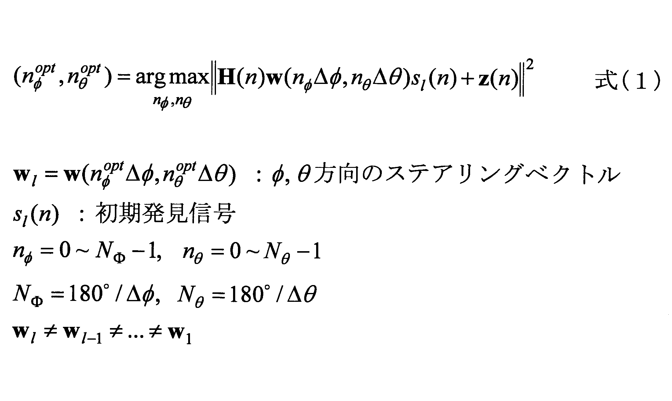
- the transmission direction (transmission direction when viewed from the base station 1) of the initial discovery signal having the maximum received power among the initial discovery signals received by the mobile station 4 is expressed by the following equation (1). be able to.
- ⁇ and ⁇ in equation (1) are respectively a beam angle ( ⁇ ) on the xy plane (horizontal direction with respect to the antenna surface) and a yz plane (perpendicular direction to the antenna surface).
- W is a steering vector of “the number of transmission antenna elements” ⁇ 1 indicating a weight amount to be multiplied by each antenna element in the phase control unit 1012 in order to transmit a beam in the ( ⁇ , ⁇ ) direction.
- ⁇ ” and “ ⁇ ” indicate intervals in the beam transmission direction in the horizontal direction and the vertical direction. For example, when beams are transmitted at 10 ° intervals in the horizontal direction and the vertical direction, “ ⁇ ” and “ ⁇ ” are each 10 °.
- “H” is a true channel and “z” is noise.
- Opt is an abbreviation of “optimal” and is given for convenience in order to express the transmission direction.
- step S ⁇ b> 103 the selection unit 106 of the base station 1 selects a beam that is actually used for signal transmission from the plurality of initial beam candidates notified from the mobile station 4.
- the selected beam is referred to as an “initial beam”.
- the selection unit 106 of the base station 1 may select as many initial beam candidates as the initial beam among the initial beam candidates notified from the mobile station 4 in order of the received power, or select the selected “L” ” May be selected as the initial beam. In the latter case, the base station 1 can avoid using a beam whose reception power on the mobile station 4 side is too low to be suitable for communication.
- the calculation unit 105 of the base station 1 determines a matrix in which steering vectors “W” corresponding to the transmission directions of the selected plurality of initial beams are arranged as an initial BF weight matrix “W ini ”.
- W ini is a matrix of “number of transmitting antenna elements” ⁇ “number of initial beams”.
- step S104 the signal transmission unit 101 of the base station 1 transmits a reference signal orthogonalized using a plurality of initial beams. More specifically, the signal transmission unit 101 sets the initial BF weight matrix “W ini ” in the phase control unit 1012 so that a beam is formed in each direction of the initial beam, so that the plurality of initial beams A reference signal corresponding to each is transmitted.
- “Q” is a subcarrier interval in which a reference signal corresponding to one initial beam is repeatedly mapped. For example, in the example of FIG. 12, three resources at the position “h” are illustrated, but the three resources mean that the same reference signal is transmitted using beams in the same direction. The same applies to resources at positions “i”, “m”, and “n”.
- Q may be any interval, but at least the number that can reproduce the frequency selectivity of the channel (sampling theorem) so that the mobile station 4 can complement the channel estimation value in all subcarriers. It is desirable that the number satisfy a certain condition.
- the reference signal corresponding to the initial beam is time-multiplexed at the time of “R” / “Q”, so that the transmission direction of all the initial beams is An orthogonal reference signal is transmitted.
- the base station 1 and the mobile station 4 may hold in common a table indicating which subcarrier and at which time the reference signal of which initial beam is transmitted. To the mobile station 4 via the base station 2 of the macro cell.
- step S105 the measurement unit 203 of the mobile station 4 receives a reference signal corresponding to the initial beam, and performs channel estimation using the received reference signal. Further, the notification unit 204 of the mobile station 4 notifies the base station 1 of channel information. As described in step S104, since the reference signal is transmitted after being multiplied by the initial BF weight matrix “W ini ”, the channel estimated by the mobile station 4 is a channel multiplied by the initial BF weight.
- step S106 the calculation unit 105 of the base station 1 uses the channel information notified from the mobile station 4 to generate a precoding matrix to be used when transmitting user data.
- the calculation unit 105 may generate the precoding matrix by any method.
- the calculation unit 105 may generate a precoding matrix using block diagonalization or an eigenmode method, or may select a precoding matrix corresponding to a channel estimation value from a codebook prepared in advance. May be.
- the signal transmission unit 101 of the base station 1 uses a beam having a shorter interval (for example, an interval of 5 °) than the initial beam in a plurality of transmission directions within a predetermined range from the transmission direction of the plurality of initial beams.
- An orthogonal update discovery signal is transmitted.
- the direction in which the update discovery signal is transmitted and the number of beams may be selected in any manner. For example, assuming that there are four initial beams as shown in FIG. 6A) and the four initial beams are transmitted at intervals of 10 ° in the horizontal and vertical directions, the signal transmission unit 101 is shown in FIG.
- the update discovery signal may be transmitted in the direction shifted by 5 ° (interval of half of the initial beam) in the horizontal or / and vertical direction around the transmission direction of each of the four initial beams. Good.
- the signal transmission unit 101 of the base station 1 may transmit the update discovery signal only in the transmission direction within a predetermined range from the initial beam whose reception power is equal to or greater than a predetermined threshold among the initial beams. Good. This is because even if the update discovery signal is transmitted in the vicinity of the transmission direction of the initial beam candidate with low reception power, the reception power (reception power of the update discovery signal) at the mobile station 4 is assumed to be low.
- the base station 1 can simultaneously transmit the number of beams “L”, but it is assumed that the number of update discovery signals to be transmitted is less than “L”. In such a case, when transmitting the update discovery signal, the signal transmission unit 101 of the base station 1 uses the frequency of the user data multiplied by the precoding matrix generated in the processing procedure of step S106 and the update discovery signal. Multiplex and transmit.
- the signal transmission unit 101 maps a plurality of update discovery signals to be transmitted in different directions to different subcarriers, and maps user data so as to be sandwiched between update discovery signals. To send. Further, the signal transmission unit 101 repeatedly maps a plurality of update discovery signals to be transmitted in different directions to predetermined subcarriers above and below the band.
- the example in FIG. 12 is merely an example, and the subcarriers to which the update discovery signal is mapped may not necessarily be above and below the band. For example, it may be a subcarrier within a predetermined range of the band.
- the base station 1 and the mobile station 4 determines in advance between the base station 1 and the mobile station 4 as to which subcarrier and at what time the update discovery signal is transmitted in which direction. For example, the base station 1 and the mobile station 4 hold in common a table indicating which subcarrier and at which time the update discovery signal is transmitted in which direction. The mobile station 4 can grasp in which direction the received update discovery signal is transmitted by comparing the table with the subcarrier and time at which the update discovery signal is received.
- the signal transmission unit 101 sets an initial BF weight matrix “W ini ” in the phase control unit 1012 in advance and sets a precoding vector for angle offset for transmitting the discovery signal for update in a desired direction.
- control is performed so that each of the plurality of update discovery signals is transmitted in a desired direction.
- the signal transmission unit 101 transmits an angle corresponding to the difference between the transmission direction of the initial discovery signal and the transmission angle of the initial discovery signal.
- the analog BF and the digitally processed BF are used together to transmit each of the plurality of update discovery signals in a desired direction.
- the precoding vector (v) for angle offset for transmitting the update discovery signal in a desired direction can be generated by using the following equation (2).
- the steering vector in the direction to be searched is a vector composed of elements indicating weights for transmitting a plurality of update discovery signals in desired directions.
- the generated angular offset precoding vector “v” is a vector composed of elements indicating weights to be multiplied to each of the plurality of update discovery signals.
- “Can” is an abbreviation for candidate, and is given for convenience in order to express the search direction.
- FIG. 14 is a diagram for explaining a signal processing method when transmitting a frequency-multiplexed discovery update signal and user data.
- the precoding processing unit 1011 multiplies a plurality of update discovery signals transmitted on the subcarriers shown in FIG. 12 by a precoding vector (v) for angle offset, and FIG.
- the frequency domain signal of each beam is generated by multiplying the user data transmitted by the indicated subcarrier by the precoding matrix obtained in the processing procedure of step S106.
- the frequency domain signal of each beam is converted into a time domain signal by IFFT, and the phase controller 1012 multiplies the weight for each antenna element by a preset initial BF weight matrix “W ini ”. Sent in the direction.
- the number of beams shown in FIG. 14 is intended to be the sum of the number of update discovery signals to be transmitted and the number of streams to transmit user data. For example, when a 16-direction update discovery signal and two streams of user data are transmitted, the number of beams shown in FIG.
- the measurement unit 203 of the mobile station 4 receives the update discovery signal transmitted from the base station 1, and receives the reception power of the received update discovery signal (more specifically, the same update discovery signal is received). Measure the average received power of multiple mapped subcarriers).
- the notification unit 204 notifies the base station 1 of the received power of the measured update discovery signal and information indicating in which direction the measured update discovery signal is transmitted in descending order of the received power. To do. For example, when the mobile station 4 receives four update discovery signals, the mobile station 4 notifies the base station 1 of information indicating the reception power and transmission direction of each of the four update discovery signals. Note that the mobile station 4 may notify the base station 1 of information indicating the received power and the transmission method via the base station 2 of the macro cell.
- updated beam candidates a plurality of beams in the order of received power notified from the mobile station 4 are referred to as “updated beam candidates”.
- the selection unit 106 of the base station 1 selects a beam actually used for data transmission from the updated beam candidates notified from the mobile station 4.
- the selected beam is referred to as “updated beam”.
- the selection unit 106 of the base station 1 may select the “updated beam candidate” as it is as the “updated beam candidate”, or receive power (mobile station 4) from the “updated beam candidate”.
- a predetermined number of beams may be selected as the “updated beams” in descending order of the received power notified from (1).
- the selection unit 106 may select a beam whose received power is equal to or greater than a predetermined threshold from the updated beam candidates as the “updated beam”.
- the base station 1 can avoid using a beam that is not suitable for communication because the received power at the mobile station 4 side is too low.
- a matrix obtained by arranging steering vector "W” corresponding to the transmission direction of each beam after multiple updates is determined as BF weight matrix of the updated "W update”.
- W update is a matrix of “number of transmitting antenna elements” ⁇ “number of beams after update”.
- step S110 the calculation unit 105 of the base station 1 multiplies the channel information notified from the mobile station 4 in step S105 by the pseudo inverse matrix of the initial BF weight matrix “W ini ” to obtain the original channel information (initial (Channel not multiplied by BF weight) is calculated, and the calculated original channel information is multiplied by the updated BF weight matrix “W update ” to calculate channel information corresponding to the updated beam.
- the calculation unit 105 generates (updates) a precoding matrix for data transmission from channel information corresponding to the updated beam.
- the method for generating the precoding matrix may be the same as in step S106.
- step S111 the signal transmission unit 101 of the base station 1 sets the precoding matrix updated in the processing procedure of step S110 in the precoding processing unit 1011 and controls the phase of the updated BF weight matrix “W update ”.
- Set in the unit 1012 user data is transmitted in a plurality of streams.
- a base station in a wireless communication system including a base station and a mobile station that communicates with the base station, and performing beam forming from the base station, the transmission directions are different from each other.
- the transmission directions are different from each other.
- a second discovery signal is transmitted in each of a plurality of second transmission directions that are within a predetermined range from the first transmission direction.
- a second discovery signal transmission unit wherein the second discovery signal transmission unit transmits each second discovery signal among the plurality of second discovery signals.
- the first being within the predetermined range from a discovery signal;
- the base station performs beamforming in the same transmission direction as each of the one or more first transmission directions corresponding to the one or more first discovery signals notified from the mobile station.
- a reference signal transmission unit that transmits one or more reference signals, an acquisition unit that acquires channel information estimated using the one or more reference signals from the mobile station, and generated based on the channel information
- a data transmission unit that transmits user data to be transmitted to the mobile station using a precoding matrix for user data transmission.
- the base station 1 can transmit user data using the beam determined by the first beam search.
- the data transmission unit may transmit user data to be transmitted to the mobile station by frequency-multiplexing with the plurality of second discovery signals.
- the base station 1 can efficiently use radio resources and reduce the transmission delay of user data.
- the data transmission unit multiplies the channel information by an inverse matrix of the first weight matrix, and transmits a second discovery signal notified from the mobile station among the plurality of second discovery signals. Multiplying a second weight matrix for beamforming in the direction to generate updated channel information, and using the precoding matrix for user data transmission generated by the updated channel information User data to be transmitted to the mobile station may be transmitted. Accordingly, user data can be transmitted using a beam in a more accurate direction, and communication stability and throughput can be improved.
- the first discovery signal transmission unit transmits the plurality of first discovery signals at predetermined intervals in the horizontal direction and the vertical direction with respect to the antenna surface
- the second discovery signal transmission unit is configured in a predetermined range from a transmission direction of the first discovery signal notified from the mobile station, at an angle of the predetermined interval in a horizontal direction and a vertical direction with respect to the antenna surface.
- the second discovery signal may be transmitted at every small interval angle.
- the base station 1 can transmit the update discovery signal at a finer angle, and can search for a more accurate beam transmission direction.
- the first discovery signal transmission unit maps the plurality of first discovery signals to different subcarriers for transmission
- the second discovery signal transmission unit may map the plurality of second discovery signals to different subcarriers for transmission.
- the base station 1 can transmit a plurality of initial discovery signals and update discovery signals at the same time, and can search for the beam transmission direction in a shorter time.
- the first discovery signal transmission unit repeatedly maps and transmits the plurality of first discovery signals to a plurality of subcarriers arranged at a predetermined interval
- the second discovery signal transmission unit may repeatedly transmit the plurality of second discovery signals by repeatedly mapping the plurality of second discovery signals to a plurality of subcarriers at a predetermined interval.
- the second discovery signal transmission unit applies the correction precoding vector to a precoder by digital processing, and the one of the plurality of first discovery signals notified from the mobile station.
- the one or more first weight matrices for performing beamforming in each of the one or more first transmission directions of the first discovery signal may be applied to a phase shifter using an analog circuit. Good.
- the discovery signal for update can be efficiently transmitted in the hybrid Massive MIMO base station.
- each device base station 1 / mobile station 4
- the configuration of each device (base station 1 / mobile station 4) described in the embodiment of the present invention is realized by executing a program by a CPU (processor) in the device including a CPU and a memory. It may be a configuration, may be a configuration realized by hardware such as a hardware circuit provided with processing logic described in the present embodiment, or may be a mixture of programs and hardware Good.
- the operations of a plurality of functional units may be physically performed by one component, or the operations of one functional unit may be physically performed by a plurality of components.
- the order of the sequences and flowcharts described in the embodiments may be changed as long as there is no contradiction.
- the base station 1 / mobile station 4 has been described using a functional block diagram, but such a device may be implemented in hardware, software, or a combination thereof.
- the software operated by the processor of the base station 1 according to the embodiment of the present invention and the software operated by the processor of the mobile station 4 according to the embodiment of the present invention are random access memory (RAM), flash memory, read-only, respectively. It may be stored in any appropriate storage medium such as a memory (ROM), EPROM, EEPROM, register, hard disk (HDD), removable disk, CD-ROM, database, server or the like.
- notification of information is not limited to the aspect / embodiment described in this specification, and may be performed by other methods.
- notification of information includes physical layer signaling (for example, Downlink Control Information (DCI), Uplink Control Information (UCI)), upper layer signaling (for example, RRC signaling, MAC signaling, broadcast information (Master Information Block (MIB), System Information Block (SIB))), other signals, or a combination thereof.
- the RRC message may be referred to as RRC signaling.
- the RRC message may be, for example, an RRC connection setup (RRCRRConnection Setup) message, an RRC connection reconfiguration (RRC Connection Reconfiguration) message, or the like.
- LTE Long Term Evolution
- LTE-A LTE-Advanced
- SUPER 3G IMT-Advanced
- 4G 5G
- Future Radio Access FAA
- W-CDMA Wideband Code Division Multiple Access
- GSM registered trademark
- CDMA2000 Code Division Multiple Access 2000
- UMB Ultra Mobile Broadband
- IEEE 802.11 Wi-Fi
- IEEE 802.16 WiMAX
- IEEE 802.20 Ultra-WideBand
- the present invention may be applied to a Bluetooth (registered trademark), a system using another appropriate system, and / or a next generation system extended based on the system.
- the determination or determination may be performed by a value represented by 1 bit (0 or 1), may be performed by a true value (Boolean: true or false), or may be performed by comparing numerical values (for example, (Comparison with a predetermined value).
- the channel and / or symbol may be a signal.
- the signal may be a message.
- UE is a subscriber station, mobile unit, subscriber unit, wireless unit, remote unit, mobile device, wireless device, wireless communication device, remote device, mobile subscriber station, access terminal, mobile terminal, wireless terminal by those skilled in the art , Remote terminal, handset, user agent, mobile client, client, or some other appropriate terminology.
- notification of predetermined information is not limited to explicitly performed, but is performed implicitly (for example, notification of the predetermined information is not performed). Also good.
- determining may encompass a wide variety of actions.
- “Judgment”, “decision” can be, for example, calculating, computing, processing, deriving, investigating, looking up (eg, table, database or another (Searching in the data structure), and confirming (ascertaining) what has been confirmed may be considered as “determining” or “determining”.
- “determination” and “determination” include receiving (for example, receiving information), transmitting (for example, transmitting information), input (input), output (output), and access. (accessing) (e.g., accessing data in a memory) may be considered as “determined” or "determined”.
- determination and “decision” means that “resolving”, “selecting”, “choosing”, “establishing”, and “comparing” are regarded as “determining” and “deciding”. May be included. In other words, “determination” and “determination” may include considering some operation as “determination” and “determination”.
- the phrase “based on” does not mean “based only on”, unless expressly specified otherwise. In other words, the phrase “based on” means both “based only on” and “based at least on.”
- the input / output information or the like may be stored in a specific place (for example, a memory) or may be managed by a management table. Input / output information and the like can be overwritten, updated, or additionally written. The output information or the like may be deleted. The input information or the like may be transmitted to another device.
- the notification of the predetermined information is not limited to explicitly performed, and may be performed implicitly (for example, notification of the predetermined information is not performed). .
- the initial discovery signal is an example of a first discovery signal.
- the update discovery signal is an example of a second discovery signal.
- the signal transmission unit 101 is an example of a first discovery signal transmission unit, a second discovery signal transmission unit, a reference signal transmission unit, and a data transmission unit.
- the angle offset precoding vector (v) is an example of a “correction precoding vector”.
Landscapes
- Engineering & Computer Science (AREA)
- Signal Processing (AREA)
- Computer Networks & Wireless Communication (AREA)
- Computer Security & Cryptography (AREA)
- Mobile Radio Communication Systems (AREA)
- Radio Transmission System (AREA)
Abstract
基地局からビームフォーミングを行うことで、それぞれ異なる送信方向に複数の第一の発見信号を送信し、前記移動局から通知された1つ以上の第一の発見信号に対応する1つ以上の第一の送信方向それぞれについて、該第一の送信方向から所定の範囲内である複数の第二の送信方向それぞれにおいて、第二の発見信号を送信し、各第二の発見信号を送信する際、該第二の発見信号から前記所定の範囲内である前記第一の送信方向と、送信すべき該第二の発見信号の第二の送信方向との送信角度の差分を該第一の送信方向に付与するための補正用のプリコーディングベクトルを該送信すべき第二の発見信号に乗算すると共に、該補正用のプリコーディングベクトルが乗算された第二の発見信号に対して、該第二の発見信号から前記所定の範囲内である前記第一の送信方向にビームフォーミングを行うための第一のウェイト行列を用いてビームフォーミングを行うことで、該第二の発見信号を送信する基地局。
Description
本発明は、基地局に関する。
LTE(Long Term Evolution)では、システム容量の更なる大容量化、データ伝送速度の更なる高速化、無線区間における更なる低遅延化などを実現するために、5Gと呼ばれる無線通信方式の検討が進んでいる。5Gでは、10Gbps以上のスループットを実現しつつ無線区間の遅延を1ms以下にするという要求条件を満たすために、様々な要素技術の検討が行われている。
5Gでは、LTEよりも更に高周波数帯を使用することが想定されている。ここで、高周波数帯では伝搬ロスが増大することから、それを補うために、ビーム幅の狭いビームフォーミングを行うMassiveMIMO(Multi Input Multi Output)を適用することが検討されている。MassiveMIMOは、基地局側に多数(例:100素子)のアンテナ素子を設置する大規模MIMOであり、狭い領域に電界の強さを集中させることができるため、ユーザ間の干渉を小さくすることができる。
図1Aは、LTE等の従来の基地局が行うビームフォーミングの例を示しており、図1Bは、MassiveMIMOを用いる基地局が行うビームフォーミングの例を示している。図1Bに示すように、ビーム幅の狭いビームフォーミングにより、遠方まで無線信号を送信することができるようになる。また、MassiveMIMOでは、基地局と移動局との間で複数のビームを高度に制御しながら空間多重を行うことで、高速通信を実現することができる。図2は、基地局及び移動局の両方でビームフォーミングを行いつつ2つのビームを空間多重させた場合の例を示している。
株式会社NTTドコモ、"ドコモ5Gホワイトペーパー"、2014年9月
株式会社NTTドコモ、NTT DOCOMOテクニカルジャーナル"5Gマルチアンテナ技術"、2016年1月
一般的なMassiveMIMO基地局の無線機は、送信アンテナ素子数と同じ数のDAC(Digital Analog Converter)及びアップコンバーターを備えると共に、ベースバンド信号処理におけるIFFT(Inverse Fast Fourier Transform)及びガードインターバルの挿入を送信アンテナ素子の数だけ行う。このようなMassiveMIMO基地局は、フルデジタル型のMassiveMIMO基地局とも呼ばれる。
フルデジタル型のMassiveMIMO基地局は、無線回路数が膨大になることから高コストである。そこで、ビームフォーミング(BF:Beam Forming)処理のみをRF(Radio Frequency)回路内の可変移相器で実現し、BF処理を全サブキャリアで共通化するように無線回路を構成する、ハイブリッド型のMassiveMIMO基地局が検討されている。ハイブリッド型のMassiveMIMO基地局ではBF処理をアナログ回路で行うため、DAC及びアップコンバーターを同時に送信するビーム数分だけ用意すればよく、デジタル回路によるベースバンド信号処理においてもIFFT及びガードインターバルの挿入をビーム数分だけ行うようにすればよい。そのため、ハイブリッド型のMassiveMIMO基地局は、フルデジタル型のMassiveMIMO基地局よりもコストを低減することが可能である。図3に、ハイブリッド型のBFを実現する基地局及び移動局の回路構成の一例を示す。図3(左側)の回路構成例は、ハイブリッド型のMassiveMIMO基地局の回路構成例を示している。図3(右側)の回路構成例は、ハイブリッド型のMassiveMIMO基地局と同様の回路構成を受信側に適用した場合の移動局の回路構成の一例を示している。
ハイブリッド型のMassiveMIMO基地局を用いて複数のビームによる空間多重(MIMO)を行う場合、MassiveMIMO基地局は、アナログBFにより移動局に最適な方向に複数のビームを向けて参照信号を送信することで、移動局から当該複数のビームにおけるチャネル情報(CSI:Channel State Information)をフィードバックさせ、フィードバックされたチャネル情報を用いて適切なプリコーディング行列を算出してデジタルによるプリコーディング処理を行うという手順を行うことになる。すなわち、ハイブリッド型のMassiveMIMO基地局は、最初にアナログBFによりビームを向ける方向を探索する必要がある。
アナログBFによりビームを向ける方向を探索する方法として、例えば、基地局は、水平方向及び垂直方向に所定の間隔の角度で離散的にビームを送信し、移動局からどの方向のビームの受信電力が最も大きいのかをフィードバックさせる方法が考えられる。この場合、探索精度を向上させるためには、水平方向及び垂直方向における角度をより細かく離散化することが必要であるが、離散化する数が多いと基地局から送信すべきビーム数が膨大になるという問題がある。例えば、図4Aに示すように水平方向及び垂直方向に10°おきに複数のビームを送信する場合、ビームの送信方向の候補としては324通りの候補が存在する。一方、図4Bに示すように水平方向及び垂直方向に5°おきに複数のビームを送信しようとすると、ビームの送信方向の候補としては、図4Aの4倍の1296通りの候補が存在することになってしまう。
移動局からどの方向のビームの受信電力が最も大きいのかをフィードバックさせるためには、ビーム毎に直交化された信号を全てのビームの送信方向の候補に対して送信する必要があるため、大量の無線リソースを消費することになる。また、探索精度を向上させようとするとビームの送信方向の候補が膨大になり、更に大量の無線リソースを消費することになってしまう。
開示の技術は上記に鑑みてなされたものであって、MassiveMIMOをサポートする無線通信システムにおいて、ビームの送信方向を効率的に探索することが可能な技術を提供することを目的とする。
開示の技術の基地局は、基地局と、前記基地局と通信する移動局とを備える無線通信システムにおける基地局であって、
当該基地局から、ビームフォーミングを行うことで、それぞれ異なる送信方向に複数の第一の発見信号を送信する第一の発見信号送信部と、前記複数の第一の発見信号のうち、前記移動局から通知された1つ以上の第一の発見信号に対応する前記複数の送信方向のうちの1つ以上の第一の送信方向それぞれについて、該第一の送信方向から所定の範囲内である複数の第二の送信方向それぞれにおいて、第二の発見信号を送信する第二の発見信号送信部と、を有し、前記第二の発見信号送信部は、前記複数の第二の発見信号のうちの各第二の発見信号を送信する際、該第二の発見信号から前記所定の範囲内である前記第一の送信方向と、送信すべき該第二の発見信号の第二の送信方向との送信角度の差分を該第一の送信方向に付与するための補正用のプリコーディングベクトルを該送信すべき第二の発見信号に乗算すると共に、該補正用のプリコーディングベクトルが乗算された第二の発見信号に対して、該第二の発見信号から前記所定の範囲内である前記第一の送信方向にビームフォーミングを行うための第一のウェイト行列を用いてビームフォーミングを行うことで、該第二の発見信号を送信する。
当該基地局から、ビームフォーミングを行うことで、それぞれ異なる送信方向に複数の第一の発見信号を送信する第一の発見信号送信部と、前記複数の第一の発見信号のうち、前記移動局から通知された1つ以上の第一の発見信号に対応する前記複数の送信方向のうちの1つ以上の第一の送信方向それぞれについて、該第一の送信方向から所定の範囲内である複数の第二の送信方向それぞれにおいて、第二の発見信号を送信する第二の発見信号送信部と、を有し、前記第二の発見信号送信部は、前記複数の第二の発見信号のうちの各第二の発見信号を送信する際、該第二の発見信号から前記所定の範囲内である前記第一の送信方向と、送信すべき該第二の発見信号の第二の送信方向との送信角度の差分を該第一の送信方向に付与するための補正用のプリコーディングベクトルを該送信すべき第二の発見信号に乗算すると共に、該補正用のプリコーディングベクトルが乗算された第二の発見信号に対して、該第二の発見信号から前記所定の範囲内である前記第一の送信方向にビームフォーミングを行うための第一のウェイト行列を用いてビームフォーミングを行うことで、該第二の発見信号を送信する。
開示の技術によれば、MassiveMIMOをサポートする無線通信システムにおいて、ビームの送信方向を効率的に探索することが可能な技術が提供される。
以下、図面を参照して本発明の実施の形態を説明する。なお、以下で説明する実施の形態は一例に過ぎず、本発明が適用される実施の形態は、以下の実施の形態に限られるわけではない。例えば、本実施の形態に係る無線通信システムはLTE又は5Gに準拠した方式のシステムを想定しているが、本発明はLTE又は5Gに限定されるわけではなく、他の方式にも適用可能である。
<システム構成>
図5は、実施の形態に係る無線通信システムの構成例を示す図である。実施の形態に係る無線通信システムは、ハイブリッド型のMassiveMIMOをサポートする基地局1と、マクロセルを形成する基地局2と、中央制御局3と、移動局4とを含む。基地局1は、多数のアンテナ素子を有しており、MassiveMIMOセル(MMセル)を形成している。なお、MMセルとは、基地局1から送信される多数のビームにより形成されるセルを意図している。MMセルでは、例えば5GHz以上で帯域幅が100MHz以上のバンド等を用いることで、マクロセルよりも高速な通信を実現することができる。
図5は、実施の形態に係る無線通信システムの構成例を示す図である。実施の形態に係る無線通信システムは、ハイブリッド型のMassiveMIMOをサポートする基地局1と、マクロセルを形成する基地局2と、中央制御局3と、移動局4とを含む。基地局1は、多数のアンテナ素子を有しており、MassiveMIMOセル(MMセル)を形成している。なお、MMセルとは、基地局1から送信される多数のビームにより形成されるセルを意図している。MMセルでは、例えば5GHz以上で帯域幅が100MHz以上のバンド等を用いることで、マクロセルよりも高速な通信を実現することができる。
基地局2はMMセルよりカバレッジが広いマクロセルを形成する。マクロセルは、LTE(LTE-A(LTE-Advanced)を含む)のセルを想定しているが、これに限られず、無線LAN等のLTE以外の無線技術を用いたセルであってもよい。すなわち、本実施の形態では、LTEのセル、無線LANのセル等と、MMセルとがオーバーラップするように配置されている。
中央制御局3は、基地局1及び基地局2を集中制御する機能を有している。例えば、中央制御局3は、基地局1及び基地局2が有する無線リソースのスケジューリング、上位レイヤ(例えばRRCレイヤ等)の制御等を行う。
移動局4は、基地局1又は基地局2と通信を行う機能を有する。図5には移動局4が1つ示されているが、本実施の形態では2つ以上の移動局4を有していてもよい。移動局4は、基地局1又は基地局2のいずれか一方と通信する機能を有していてもよいし、基地局1及び基地局2と同時に通信を行う機能(Multiple Connectivity)を有していてもよい。
<動作概要>
本実施の形態に係る基地局1は、アンテナ面に対して水平方向及び垂直方向に大まかな間隔(例えば10°間隔)で、直交された発見信号(以下、初期発見信号と呼ぶ)を送信し、移動局4からどの方向のビームで送信された初期発見信号の受信電力が大きいのかをフィードバックさせることで、アナログBFによる大まかなビームの送信方向を決定する。初期発見信号が送信される方向及び決定されたビームの送信方向のイメージを図6Aに示す。図6Aの上図は、空間を垂直方向の面で区切った場合に、初期発見信号が送信される方向、及び、決定されたビームの送信方向のイメージを図示したものであり、図6Aの下図は、基地局1の正面から見た際に、初期発見信号の到来方向、及び、決定されたビームの到来方向のイメージを図示したものである。
本実施の形態に係る基地局1は、アンテナ面に対して水平方向及び垂直方向に大まかな間隔(例えば10°間隔)で、直交された発見信号(以下、初期発見信号と呼ぶ)を送信し、移動局4からどの方向のビームで送信された初期発見信号の受信電力が大きいのかをフィードバックさせることで、アナログBFによる大まかなビームの送信方向を決定する。初期発見信号が送信される方向及び決定されたビームの送信方向のイメージを図6Aに示す。図6Aの上図は、空間を垂直方向の面で区切った場合に、初期発見信号が送信される方向、及び、決定されたビームの送信方向のイメージを図示したものであり、図6Aの下図は、基地局1の正面から見た際に、初期発見信号の到来方向、及び、決定されたビームの到来方向のイメージを図示したものである。
次に、基地局1は、大まかなビームの送信方向の周辺の方向に対し、水平方向及び垂直方向に初期発見信号よりも小さい間隔(例えば5°間隔)で、直交された発見信号(以下、更新用発見信号と呼ぶ)を送信し、移動局4からどの方向のビームで送信された更新用発見信号の受信電力が大きいのかをフィードバックさせることで、より詳細にアナログBFによるビームの送信方向を決定する。図6Bの上図は、空間を垂直方向の面で区切った場合に、更新用発見信号が送信される方向のイメージを図示したものであり、図6Bの下図は、基地局1の正面から見た際に、更新用発見信号の到来方向のイメージを図示したものである。本無線通信システムは、初期発見信号と更新用発見信号を用いた2段階の処理手順でアナログBFによるビーム送信方向を決定することで、ビーム送信方向を効率的に探索することを可能にする。
また、基地局1は、初期発見信号により決定された複数のビームの送信方向に参照信号を送信することで、移動局4から当該複数のビームのチャネル情報をフィードバックさせ、フィードバックされたチャネル情報を用いてプリコーディング行列を算出する。続いて、基地局1は、更新用発見信号と、算出したプリコーディング行列を用いて生成されるユーザデータ信号とを周波数多重して送信する。図6を用いて具体的に説明すると、基地局1は、初期発見信号により決定された複数のビーム(図6Aに示す方向のビーム)を用いてストリームを空間多重することでユーザデータを送信すると共に、図6Bに示す複数のビームで更新用発見信号を送信する。これにより、本無線通信システムは、無線リソースを効率的に利用することを可能にする。
<機能構成>
(基地局)
図7は、実施の形態に係る基地局の機能構成例を示す図である。図7Aに示すように、基地局1は、信号送信部101、信号受信部102、送信信号生成部103、取得部104、算出部105及び選択部106を有する。図7Aは、本実施の形態における主要な機能部のみを示すものであり、本無線通信システムで用いられる通信方式に準拠した動作を行うための図示しない機能も有するものである。
(基地局)
図7は、実施の形態に係る基地局の機能構成例を示す図である。図7Aに示すように、基地局1は、信号送信部101、信号受信部102、送信信号生成部103、取得部104、算出部105及び選択部106を有する。図7Aは、本実施の形態における主要な機能部のみを示すものであり、本無線通信システムで用いられる通信方式に準拠した動作を行うための図示しない機能も有するものである。
信号送信部101は、送信信号生成部103で生成された信号を無線送信する機能を有する。信号送信部101は、更に、プリコーディング処理部1011と位相制御部1012とを含む。プリコーディング処理部1011は、移動局4に向けて送信すべき複数のストリーム間の干渉を抑制するためのプリコーディング処理を行う。位相制御部1012は、アナログBFによる位相の変更を行う機能部であり、移動局4に向けて送信する複数のビームを送信する際に、各アンテナ素子に乗算すべき位相を制御する機能を有する。
図7Bに、信号送信部101の具体的な機能構成例を示す。図7Bに示すように、信号送信部101は、移動局4に向けて送信すべきM本のストリーム(周波数領域の信号)に対してプリコーディング処理を行うプリコーダー(Precoder)、送信する複数のビーム数(L)分の周波数領域の信号を逆フーリエ変換することで時間領域の信号に変換する「IFFT」、ガードインターバル(例えばサイクリックプレフィクス)を挿入する「+GI」、DA変換を行う「DAC」、アップコンバートを行う「アップコンバーター」、複数のビームごとに「NT」本の各アンテナ素子に乗算する位相を制御する移相器を含む固定ビームフォーマー(Fixed Beamformer)を含む。図7Aのプリコーディング処理部1011及び位相制御部1012は、それぞれ図7Bのプリコーダー及び固定ビームフォーマーに該当する。
信号受信部102は、移動局4から受信した物理レイヤの信号を受信すると共に、受信した信号からより上位のレイヤの信号を取得する機能を有する。
送信信号生成部103は、上位レイヤの信号から移動局4に向けて送信すべき物理レイヤの信号を生成して信号送信部101に渡す機能を有する。送信信号生成部103は、例えば、初期発見信号、更新用発見信号、参照信号及び移動局4に向けて送信するユーザデータを生成する機能を有する。なお、送信信号生成部103は、信号送信部101に含まれていてもよい。
取得部104は、移動局4から通知される各種の情報を取得する機能を有する。より具体的には、取得部104は、移動局4で受信電力が大きいと判定された初期発見信号及び更新用発見信号の送信方向、移動局4で推定されたチャネル情報(チャネル推定値、チャネル行列等)などを示す各種の情報を取得する機能を有する。
算出部105は、プリコーディング処理部1011で用いられるプリコーディング行列の算出、位相制御部1012で各アンテナ素子に乗算されるウェイトの算出など、各種の計算処理を行う機能を有する。なお、算出部105は、信号送信部101に含まれていてもよい。
選択部106は、ビーム候補(初期ビーム候補、更新後のビーム候補)の中から実際に送信すべきビーム(初期ビーム、更新後のビーム)を選択する機能を有する。初期ビーム候補、初期ビーム、更新後のビーム候補、及び更新後のビームについては後述する。選択部106は、信号送信部101に含まれていてもよい。
(移動局)
図8は、実施の形態に係る移動局の機能構成例を示す図である。図8に示すように。移動局4は、信号送信部201、信号受信部202、測定部203及び通知部204を有する。図8は、本実施の形態における主要な機能部のみを示すものであり、本無線通信システムで用いられる通信方式に準拠した動作を行うための図示しない機能も有するものである。
図8は、実施の形態に係る移動局の機能構成例を示す図である。図8に示すように。移動局4は、信号送信部201、信号受信部202、測定部203及び通知部204を有する。図8は、本実施の形態における主要な機能部のみを示すものであり、本無線通信システムで用いられる通信方式に準拠した動作を行うための図示しない機能も有するものである。
信号送信部201は、移動局4から送信されるべき上位のレイヤの信号から、物理レイヤの各種信号を生成し、無線送信する機能を含む。信号受信部202は、基地局1から各種の信号を無線受信し、受信した物理レイヤの信号からより上位のレイヤの信号を取得する機能を含む。
測定部203は、信号受信部202で受信された1以上の初期発見信号及び1以上の更新用発見信号の各々の受信電力を測定する機能を有する。また、測定部203は、信号受信部202で受信された1以上の初期発見信号及び1以上の更新用発見信号の送信方向(基地局1からの送信方向)を検出する機能を有する。また、測定部203は、基地局1から送信された参照信号を用いてチャネル推定を行う。
通知部204は、測定部203で測定された各種の情報を基地局1に通知する(フィードバックする)機能を有する。より具体的には、通知部204は、測定部203で測定された1以上の初期発見信号及び1以上の更新用発見信号の各々の送信方向と受信電力とを基地局1に通知する機能を有する。また、通知部204は、測定部203で推定されたチャネル情報(チャネル推定値、チャネル行列等)を基地局1に通知する。
以上説明した基地局1及び移動局4の機能構成は、全体をハードウェア回路(例えば、1つ又は複数のICチップ)で実現してもよいし、一部をハードウェア回路で構成し、その他の部分をCPUとプログラムとで実現してもよい。
(基地局)
図9は、実施の形態に係る基地局のハードウェア構成の一例を示す図である。図9は、図7よりも実装例に近い構成を示している。図9に示すように、基地局1は、無線信号に関する処理を行うRF(Radio Frequency)モジュール301と、ベースバンド信号処理を行うBB(Base Band)処理モジュール302と、上位レイヤ等の処理を行う装置制御モジュール303と、ネットワークと接続するためのインタフェースである通信IF304とを有する。
図9は、実施の形態に係る基地局のハードウェア構成の一例を示す図である。図9は、図7よりも実装例に近い構成を示している。図9に示すように、基地局1は、無線信号に関する処理を行うRF(Radio Frequency)モジュール301と、ベースバンド信号処理を行うBB(Base Band)処理モジュール302と、上位レイヤ等の処理を行う装置制御モジュール303と、ネットワークと接続するためのインタフェースである通信IF304とを有する。
RFモジュール301は、BB処理モジュール302から受信したデジタルベースバンド信号に対して、D/A(Digital-to-Analog)変換、変調、周波数変換、及び電力増幅等を行うことでアンテナから送信すべき無線信号を生成する。また、受信した無線信号に対して、周波数変換、A/D(Analog to Digital)変換、復調等を行うことでデジタルベースバンド信号を生成し、BB処理モジュール302に渡す。アナログBF回路311は、移相器及び加算器を含む。RFモジュール301は、例えば、図7に示す信号送信部101の一部、信号受信部102の一部を含む。
BB処理モジュール302は、IPパケットとデジタルベースバンド信号とを相互に変換する処理を行う。DSP(Digital Signal Processor)312は、BB処理モジュール302における信号処理を行うプロセッサである。メモリ322は、DSP312のワークエリアとして使用される。BB処理モジュール302は、例えば、図7に示す信号送信部101の一部、信号受信部102の一部、送信信号生成部103、取得部104、算出部105及び選択部106を含む。
装置制御モジュール303は、IPレイヤのプロトコル処理、OAM(Operation and Maintenance)処理等を行う。プロセッサ313は、装置制御モジュール303が行う処理を行うプロセッサである。メモリ323は、プロセッサ313のワークエリアとして使用される。補助記憶装置333は、例えばHDD等であり、基地局1自身が動作するための各種設定情報等が格納される。装置制御モジュール303は、例えば、図7に示す取得部104、算出部105及び選択部106を含んでいてもよい。
(移動局)
図10は、実施の形態に係る移動局のハードウェア構成の一例を示す図である。図10は、図8よりも実装例に近い構成を示している。図10に示すように、移動局4は、無線信号に関する処理を行うRFモジュール401と、ベースバンド信号処理を行うBB処理モジュール402と、上位レイヤ等の処理を行うUE制御モジュール403とを有する。
図10は、実施の形態に係る移動局のハードウェア構成の一例を示す図である。図10は、図8よりも実装例に近い構成を示している。図10に示すように、移動局4は、無線信号に関する処理を行うRFモジュール401と、ベースバンド信号処理を行うBB処理モジュール402と、上位レイヤ等の処理を行うUE制御モジュール403とを有する。
RFモジュール401は、BB処理モジュール402から受信したデジタルベースバンド信号に対して、D/A変換、変調、周波数変換、及び電力増幅等を行うことでアンテナから送信すべき無線信号を生成する。また、受信した無線信号に対して、周波数変換、A/D変換、復調等を行うことでデジタルベースバンド信号を生成し、BB処理モジュール402に渡す。RFモジュール401は、例えば、図8に示す信号送信部201の一部、信号受信部202の一部を含む。
BB処理モジュール402は、IPパケットとデジタルベースバンド信号とを相互に変換する処理を行う。DSP412は、BB処理モジュール402における信号処理を行うプロセッサである。メモリ422は、DSP412のワークエリアとして使用される。BB処理モジュール402は、例えば、図8に示す信号送信部201の一部、信号受信部202の一部、測定部203及び通知部204を含む。
UE制御モジュール403は、IPレイヤのプロトコル処理、各種アプリケーションの処理等を行う。プロセッサ413は、UE制御モジュール403が行う処理を行うプロセッサである。メモリ423は、プロセッサ413のワークエリアとして使用される。UE制御モジュール403は、例えば、図8に示す通知部204を含んでいてもよい。
<処理手順>
図11は、実施の形態に係る無線通信システムが行う処理手順の一例を示すシーケンス図である。図11を用いて、初期発見信号が送信されてからユーザデータの送信が行われるまでの一連の処理手順について具体的に説明する。
図11は、実施の形態に係る無線通信システムが行う処理手順の一例を示すシーケンス図である。図11を用いて、初期発見信号が送信されてからユーザデータの送信が行われるまでの一連の処理手順について具体的に説明する。
ステップS101で、基地局1の信号送信部101は、水平方向及び垂直方向に所定の間隔(例えば10°間隔)のビームで、直交された初期発見信号を送信する。ここで、図12を用いて、初期発見信号の配置例を具体的に説明する。図12において、「L」は、ある時刻にて同時に送信される初期発見信号の数を示す。図12の横軸は1OFDMシンボルであるが、あくまで一例であり他の単位(例えば複数のOFDMシンボルやサブキャリア)であってもよい。図12に示すように、それぞれ異なる送信方向に送信される直交された複数の初期発見信号は、それぞれ異なるサブキャリアに、「L」間隔で繰り返しマッピングされる。例えば、図12の例では「a」の位置のリソースがサブキャリア「L」間隔で3つ図示されているが、当該3つのリソースでは、同一の方向のビームで初期発見信号が送信されることを意味している。同様に「b」の位置のリソースには、「a」の位置のリソースにマッピングされる初期発見信号とは異なる送信方向の初期発見信号がマッピングされることを意味している。
全てのビーム送信方向の候補数分に対して「L」が小さい場合、全てのビーム送信方向の候補数/「L」の時刻で時間多重させることで、全てのビーム送信方向に対して、直交された初期発見信号が送信されるようにする。例えば図4Aで説明したように、水平方向及び垂直方向に10°おきに複数のビームを送信する場合、全てのビーム送信方向の候補数としては324通りの候補が存在する。また、本実施の形態における基地局1が同時に送信可能なビーム数が36ビームであるとする。この場合、基地局1は、9つのOFDMシンボルを用いることで、全ての送信方向に初期発見信号を送信することになる。
本実施の形態では、どのサブキャリア及びどの時刻で、どの方向にビームが送信されるのかについては、基地局1と移動局4との間で予め決定されているようにする。例えば、基地局1と移動局4は、どのサブキャリア及びどの時刻で、どの方向にビームが送信されるのかを示すテーブルを共通に保持しておくようにする。移動局4は、初期発見信号を受信したサブキャリア及び時刻とテーブルとを比較することで、受信した初期発見信号がどの方向で送信されたものなのかを把握することができる。
また、「L」は、基地局1が同時に送信可能なビーム数(つまり、図7(b)に示す回路構成において同時に送信可能なビーム数)と同一であることを想定しているが、これに限られず、同時に送信可能なビーム数以下であってもよい。しかしながら、同時に送信可能なビーム数と同一である場合、より短い時間で全ての方向に初期発見信号を送信することができる。
ステップS102で、移動局4の測定部203は、基地局1から送信された1以上の初期発見信号を受信し、受信した1以上の初期発見信号の受信電力(より具体的には同一の初期発見信号がマッピングされている複数のサブキャリアの受信電力の平均)を測定する。また、通知部204は、測定された初期発見信号の受信電力と、測定した初期発見信号がどの方向に送信されたものなのかを示す情報を、受信電力が大きい順に基地局1に通知する。移動局4は、例えば4つの初期発見信号を受信した場合、当該4つの初期発見信号の各々の受信電力及び送信方向を示す情報を基地局1に通知する。なお、移動局4は、受信電力及び送信方法を示す情報を、マクロセルの基地局2を介して基地局1に通知するようにしてもよい。以下、移動局4から通知された受信電力順の複数のビームを「初期ビーム候補」と呼ぶ。移動局4は、初期ビーム候補を、自身が受信した初期発見信号の全てについて基地局1に通知するようにしてもよいし、受信した初期発見信号の数が「L」より多い場合、受信電力順に「L」の数だけ基地局1に通知するようにしてもよい。基地局1は、最大でも「L」の数しかビームを送信することができないため、移動局4から「L」の数以上に初期ビーム候補を通知しないようにすることで、制御信号の信号量を削減することができる。
ここで、移動局4が受信する初期発見信号のうち、受信電力が最大である初期発見信号の送信方向(基地局1から見た場合の送信方向)は、以下の式(1)で表現することができる。
ステップS103で、基地局1の選択部106は、移動局4から通知された複数の初期ビーム候補の中から実際に信号送信に用いるビームを選択する。以下、選択されたビームを「初期ビーム」と呼ぶ。基地局1の選択部106は、移動局4から通知された初期ビーム候補のうち、受信電力が大きい順に「L」の数分のビームを初期ビームとして選択してもよいし、選択した「L」の数分の初期ビームの中から、更に、受信電力が所定の閾値以上であるビームを初期ビームとして選択するようにしてもよい。後者の場合、基地局1は、移動局4側での受信電力が低すぎて通信に適さないようなビームを使用しないようにすることができる。続いて、基地局1の算出部105は、選択された複数の初期ビームの各々の送信方向に対応するステアリングベクトル「W」を並べた行列を、初期BFウェイト行列「Wini」として決定する。「Wini」は、"送信アンテナ素子数"×"初期ビーム数"の行列である。
ステップS104で、基地局1の信号送信部101は、複数の初期ビームを用いて直交化された参照信号を送信する。より具体的には、信号送信部101は、位相制御部1012に初期BFウェイト行列「Wini」をセットすることで初期ビームのそれぞれの方向にビームが形成されるようにして、複数の初期ビームの各々に対応する参照信号を送信する。図12を用いて、参照信号の配置例を具体的に説明する。図12において、「R」は初期ビームの数を示している。なお、ステップS103の処理手順で「L」の数分の初期ビームが選択された場合、「R」=「L」になる。図12において、「Q」は、1つの初期ビームに対応する参照信号が繰り返しマッピングされるサブキャリア間隔である。例えば、図12の例では「h」の位置のリソースが3つ図示されているが、当該3つのリソースでは、同一方向のビームで同一の参照信号が送信されることを意味している。「i」、「m」及び「n」の位置のリソースについても同様である。
「Q」はどのような間隔であってもよいが、少なくとも移動局4が全サブキャリアにおいてチャネル推定値を補完できるようにするため、チャネルの周波数選択性が再生できる程度の数(標本化定理を満たす程度の数)であるのが望ましい。
「R」の数に対して「Q」が小さい場合、初期ビームに対応する参照信号を「R」/「Q」の時刻で時間多重させることで、全ての初期ビームの送信方向に対して、直交された参照信号が送信されるようにする。例えば初期ビームが36ビームであり、「Q」=4である場合、基地局1は、9つのOFDMシンボルを用いることで、全ての初期ビームに対応する参照信号を送信することになる。
なお、どのサブキャリア及びどの時刻で、どの初期ビームの参照信号が送信されるのかについては、基地局1と移動局4との間で予め決定されているようにする。例えば、基地局1と移動局4は、どのサブキャリア及びどの時刻で、どの初期ビームの参照信号が送信されるのかを示すテーブルを共通に保持しておくようにしてもよいし、基地局1からマクロセルの基地局2を介して移動局4に予め通知するようにしてもよい。
ステップS105で、移動局4の測定部203は、初期ビームに対応する参照信号を受信し、受信した参照信号を用いてチャネル推定を行う。また、移動局4の通知部204は、チャネル情報を基地局1に通知する。なお、ステップS104で説明した通り、当該参照信号は初期BFウェイト行列「Wini」が乗算されて送信されるため、移動局4で推定するチャネルは、初期BFウェイトが乗算されたチャネルである。
ステップS106で、基地局1の算出部105は、移動局4から通知されたチャネル情報を用いて、ユーザデータの送信時に用いるプリコーディング行列を生成する。なお、算出部105はどのような方法でプリコーディング行列を生成してもよい。例えば、算出部105は、ブロック対角化や固有モード法を用いてプリコーディング行列を生成してもよいし、予め用意されたコードブックからチャネル推定値に対応するプリコーディング行列を選択するようにしてもよい。
ステップS107で、基地局1の信号送信部101は、複数の初期ビームの送信方向から所定の範囲内である複数の送信方向に、初期ビームよりも短い間隔(例えば5°間隔)のビームで、直交された更新用発見信号を送信する。更新用発見信号を送信する方向及びビームの数はどのように選択されてもよい。例えば、初期ビームが図6A)に示すように4つ存在し、当該4つの初期ビームが水平及び垂直方向に10°間隔で送信されていると仮定した場合、信号送信部101は、図6Bに示すように、4つの初期ビームの各々の送信方向を中心に、例えば水平又は/及び垂直方向に5°(初期ビームの半分の間隔)ずらした方向で更新用発見信号を送信するようにしてもよい。
なお、基地局1の信号送信部101は、初期ビームのうち、受信電力が所定の閾値以上である初期ビームから所定の範囲内の送信方向に限って更新用発見信号を送信するようにしてもよい。受信電力が低い初期ビーム候補の送信方向の周辺で更新用発見信号を送信しても、移動局4における受信電力(更新用発見信号の受信電力)は低いと想定されるためである。
ここで、基地局1は、「L」の数だけ同時にビームを送信することができるが、送信すべき更新用発見信号の数が「L」より少ない場合が想定される。このような場合、基地局1の信号送信部101は、更新用発見信号を送信する際に、ステップS106の処理手順で生成したプリコーディング行列が乗算されたユーザデータと更新用発見信号とを周波数多重させて送信する。
図12を用いて、更新用発見信号とユーザデータの配置例を具体的に説明する。図12に示すように、信号送信部101は、それぞれ異なる方向に送信すべき複数の更新用発見信号を、それぞれ異なるサブキャリアにマッピングすると共に、ユーザデータを更新用発見信号で挟み込むようにマッピングして送信する。また、信号送信部101は、それぞれ異なる方向に送信すべき複数の更新用発見信号を、帯域の上下における所定のサブキャリアに繰り返しマッピングする。なお、図12の例では、あくまで一例であり、更新用発見信号がマッピングされるサブキャリアは必ずしも帯域の上下でなくてもよい。例えば、帯域の所定の範囲内のサブキャリアであってもよい。なお、どのサブキャリア及びどの時刻で、どの方向の更新用発見信号が送信されるのかについては、基地局1と移動局4との間で予め決定されているようにする。例えば、基地局1と移動局4は、どのサブキャリア及びどの時刻で、どの方向の更新用発見信号が送信されるのかを示すテーブルを共通に保持しておくようにする。移動局4は、更新用発見信号を受信したサブキャリア及び時刻とテーブルとを比較することで、受信した更新用発見信号がどの方向で送信されたものなのかを把握することができる。
また、信号送信部101は、初期BFウェイト行列「Wini」を位相制御部1012に予めセットしておくと共に、更新用発見信号を所望の方向に送信するための角度オフセット用のプリコーディングベクトルをプリコーディング処理部1011に予めセットしておくことで、複数の更新用発見信号の各々が所望の方向に送信されるように制御する。言い換えると、信号送信部101は、更新用発見信号を所望の方向に送信するために、初期発見信号の送信方向と当該所望の方向との送信角度の差分に相当する角度を初期発見信号の送信方向に対して付与するための角度オフセット用のプリコーディングベクトルと、初期発見信号の送信方向に対応するウェイト行列(初期BFウェイト行列)との両方を用いることで、アナログBFとデジタル処理によるBFとを併用して複数の更新用発見信号の各々を所望の方向に送信する。ここで、更新用発見信号を所望の方向に送信するための角度オフセット用のプリコーディングベクトル(v)は、以下に示す式(2)を用いることで生成することができる。なお、式(2)において、探索したい方向のステアリングベクトルとは、複数の更新用発見信号をそれぞれ所望の方向に送信するためのウェイトを示す要素から構成されるベクトルである。また、生成される角度オフセット用のプリコーディングベクトル「v」は、複数の更新用発見信号の各々に乗算されるウェイトを示す要素から構成されるベクトルである。「can」はcandidateの略であり、探索方向を表現するために便宜上付与したものである。

ステップS108で、移動局4の測定部203は、基地局1から送信される更新用発見信号を受信し、受信した更新用発見信号の受信電力(より具体的には同一の更新用発見信号がマッピングされている複数のサブキャリアの受信電力の平均)を測定する。また、通知部204は、測定された更新用発見信号の受信電力と、測定した更新用発見信号がどの方向に送信されたものなのかを示す情報を、受信電力が大きい順に基地局1に通知する。移動局4は、例えば4つの更新用発見信号を受信した場合、当該4つの更新用発見信号の各々の受信電力及び送信方向を示す情報を基地局1に通知する。なお、移動局4は、受信電力及び送信方法を示す情報を、マクロセルの基地局2を介して基地局1に通知するようにしてもよい。以下、移動局4から通知された受信電力順の複数のビームを「更新後のビーム候補」と呼ぶ。
ステップS109で、基地局1の選択部106は、移動局4から通知された更新後のビーム候補の中から実際にデータ送信に用いるビームを選択する。以下、選択されたビームを「更新後のビーム」と呼ぶ。基地局1の選択部106は、「更新後のビーム候補」をそのまま「更新後のビーム」として選択するようにしてもよいし、「更新後のビーム候補」のうち、受信電力(移動局4から通知された受信電力)が大きい順に所定の数のビームを「更新後のビーム」として選択するようにしてもよい。また、選択部106は、更新後のビーム候補の中から、受信電力が所定の閾値以上であるビームを「更新後のビーム」として選択するようにしてもよい。これにより、基地局1は、移動局4側での受信電力が低すぎて通信に適さないようなビームをデータ送信に使用しないようにすることができる。
続いて、算出部105は、複数の更新後のビームの各々の送信方向に対応するステアリングベクトル「W」を並べた行列を、更新後のBFウェイト行列「Wupdate」として決定する。「Wupdate」は、"送信アンテナ素子数"×"更新後のビーム数"の行列である。
ステップS110で、基地局1の算出部105は、ステップS105で移動局4から通知されたチャネル情報に初期BFウェイト行列「Wini」の疑似逆行列を乗算することで、元のチャネル情報(初期BFウェイトが乗算されてないチャネル)を算出し、算出した元のチャネル情報に更新後のBFウェイト行列「Wupdate」を乗算することで、更新後のビームに対応するチャネル情報を算出する。また、算出部105は、更新後のビームに対応するチャネル情報からデータ送信用のプリコーディング行列を生成(更新)する。プリコーディング行列の生成方法は、ステップS106と同様の方法でよい。
ステップS111で、基地局1の信号送信部101は、ステップS110の処理手順で更新されたプリコーディング行列をプリコーディング処理部1011にセットすると共に、更新後のBFウェイト行列「Wupdate」を位相制御部1012にセットして、複数のストリームでユーザデータを送信する。
以上、初期発見信号が送信されてからユーザデータの送信が行われるまでの一連の処理手順について具体的に説明した。
<まとめ>
以上、実施の形態によれば、基地局と、前記基地局と通信する移動局とを備える無線通信システムにおける基地局であって、当該基地局から、ビームフォーミングを行うことで、それぞれ異なる送信方向に複数の第一の発見信号を送信する第一の発見信号送信部と、前記複数の第一の発見信号のうち、前記移動局から通知された1つ以上の第一の発見信号に対応する前記複数の送信方向のうちの1つ以上の第一の送信方向それぞれについて、該第一の送信方向から所定の範囲内である複数の第二の送信方向それぞれにおいて、第二の発見信号を送信する第二の発見信号送信部と、を有し、前記第二の発見信号送信部は、前記複数の第二の発見信号のうちの各第二の発見信号を送信する際、該第二の発見信号から前記所定の範囲内である前記第一の送信方向と、送信すべき該第二の発見信号の第二の送信方向との送信角度の差分を該第一の送信方向に付与するための補正用のプリコーディングベクトルを該送信すべき第二の発見信号に乗算すると共に、該補正用のプリコーディングベクトルが乗算された第二の発見信号に対して、該第二の発見信号から前記所定の範囲内である前記第一の送信方向にビームフォーミングを行うための第一のウェイト行列を用いてビームフォーミングを行うことで、該第二の発見信号を送信する、基地局が提供される。この基地局1によれば、MassiveMIMOをサポートする無線通信システムにおいて、ビームの送信方向を効率的に探索することが可能な技術が提供される。
以上、実施の形態によれば、基地局と、前記基地局と通信する移動局とを備える無線通信システムにおける基地局であって、当該基地局から、ビームフォーミングを行うことで、それぞれ異なる送信方向に複数の第一の発見信号を送信する第一の発見信号送信部と、前記複数の第一の発見信号のうち、前記移動局から通知された1つ以上の第一の発見信号に対応する前記複数の送信方向のうちの1つ以上の第一の送信方向それぞれについて、該第一の送信方向から所定の範囲内である複数の第二の送信方向それぞれにおいて、第二の発見信号を送信する第二の発見信号送信部と、を有し、前記第二の発見信号送信部は、前記複数の第二の発見信号のうちの各第二の発見信号を送信する際、該第二の発見信号から前記所定の範囲内である前記第一の送信方向と、送信すべき該第二の発見信号の第二の送信方向との送信角度の差分を該第一の送信方向に付与するための補正用のプリコーディングベクトルを該送信すべき第二の発見信号に乗算すると共に、該補正用のプリコーディングベクトルが乗算された第二の発見信号に対して、該第二の発見信号から前記所定の範囲内である前記第一の送信方向にビームフォーミングを行うための第一のウェイト行列を用いてビームフォーミングを行うことで、該第二の発見信号を送信する、基地局が提供される。この基地局1によれば、MassiveMIMOをサポートする無線通信システムにおいて、ビームの送信方向を効率的に探索することが可能な技術が提供される。
また、前記基地局は、前記移動局から通知された前記1つ以上の第一の発見信号に対応する前記1つ以上の第一の送信方向それぞれと同一の送信方向にビームフォーミングを行うことで1つ以上の参照信号を送信する参照信号送信部と、前記1つ以上の参照信号を用いて推定されたチャネル情報を前記移動局から取得する取得部と、前記チャネル情報に基づいて生成されたユーザデータ送信用のプリコーディング行列を用いて前記移動局に送信すべきユーザデータを送信するデータ送信部と、を有するようにしてもよい。これにより、基地局1は、最初のビーム探索により決定されるビームを用いて、ユーザデータを送信することができる。
また、前記データ送信部は、前記移動局に送信すべきユーザデータを、前記複数の第二の発見信号と周波数多重して送信するようにしてもよい。これにより、基地局1は、無線理リソースを効率的に利用することができると共に、ユーザデータの送信遅延を減少させることができる。
また、前記データ送信部は、前記チャネル情報に前記第一のウェイト行列の逆行列を乗算し、前記複数の第二の発見信号のうち、前記移動局から通知された第二の発見信号の送信方向にビームフォーミングを行うための第二のウェイト行列を乗算することで、更新されたチャネル情報を生成し、該更新されたチャネル情報により生成されたユーザデータ送信用のプリコーディング行列を用いて前記移動局に送信すべきユーザデータを送信するようにしてもよい。これにより、より正確な方向のビームを用いてユーザデータを送信することができ、通信の安定性及びスループットを向上させることが可能になる。
また、前記第一の発見信号送信部は、アンテナ面に対して水平方向及び垂直方向に所定の間隔の角度ごとに前記複数の第一の発見信号を送信し、
前記第二の発見信号送信部は、前記移動局から通知された第一の発見信号の送信方向から所定の範囲内において、アンテナ面に対して水平方向及び垂直方向に前記所定の間隔の角度よりも小さい間隔の角度ごとに第二の発見信号を送信するようにしてもよい。これにより、基地局1は、更新用発見信号をより細かい角度で送信することができ、より正確なビーム送信方向を探索することが可能になる。
前記第二の発見信号送信部は、前記移動局から通知された第一の発見信号の送信方向から所定の範囲内において、アンテナ面に対して水平方向及び垂直方向に前記所定の間隔の角度よりも小さい間隔の角度ごとに第二の発見信号を送信するようにしてもよい。これにより、基地局1は、更新用発見信号をより細かい角度で送信することができ、より正確なビーム送信方向を探索することが可能になる。
また、前記第一の発見信号送信部は、前記複数の第一の発見信号を、それぞれ異なるサブキャリアにマッピングして送信し、
前記第二の発見信号送信部は、前記複数の第二の発見信号を、それぞれ異なるサブキャリアにマッピングして送信するようにしてもよい。これにより、基地局1は、同一の時刻に複数の初期発見信号及び更新用発見信号を送信することができ、ビーム送信方向の探索をより短時間で行うことができる。
前記第二の発見信号送信部は、前記複数の第二の発見信号を、それぞれ異なるサブキャリアにマッピングして送信するようにしてもよい。これにより、基地局1は、同一の時刻に複数の初期発見信号及び更新用発見信号を送信することができ、ビーム送信方向の探索をより短時間で行うことができる。
また、前記第一の発見信号送信部は、前記複数の第一の発見信号を、所定の間隔で配置される複数のサブキャリアに繰り返しマッピングして送信し、
前記第二の発見信号送信部は、前記複数の第二の発見信号を、所定の間隔の複数のサブキャリアに繰り返しマッピングして送信するようにしてもよい。これにより、移動局4は、初期発見信号及び更新用発見信号の受信電力の測定を行う際に、複数の周波数における受信電力を平均した値を基地局1にフィードバックすることが可能になり、より正確な受信電力の測定を行うことが可能になる。
前記第二の発見信号送信部は、前記複数の第二の発見信号を、所定の間隔の複数のサブキャリアに繰り返しマッピングして送信するようにしてもよい。これにより、移動局4は、初期発見信号及び更新用発見信号の受信電力の測定を行う際に、複数の周波数における受信電力を平均した値を基地局1にフィードバックすることが可能になり、より正確な受信電力の測定を行うことが可能になる。
また、前記第二の発見信号送信部は、前記補正用のプリコーディングベクトルをデジタル処理によるプリコーダーに適用し、前記複数の第一の発見信号のうち、前記移動局から通知された前記1つ以上の第一の発見信号の前記1つ以上の第一の送信方向それぞれにビームフォーミングを行うための前記1つ以上の第一のウェイト行列をアナログ回路による移相器に適用するようにしてもよい。これにより、ハイブリッド型のMassiveMIMO基地局において、効率的に更新用発見信号の送信を行うことができる。
<実施形態の補足>
以上、本発明の実施の形態で説明する各装置(基地局1/移動局4)の構成は、CPUとメモリを備える当該装置において、プログラムがCPU(プロセッサ)により実行されることで実現される構成であってもよいし、本実施の形態で説明する処理のロジックを備えたハードウェア回路等のハードウェアで実現される構成であってもよいし、プログラムとハードウェアが混在していてもよい。
以上、本発明の実施の形態で説明する各装置(基地局1/移動局4)の構成は、CPUとメモリを備える当該装置において、プログラムがCPU(プロセッサ)により実行されることで実現される構成であってもよいし、本実施の形態で説明する処理のロジックを備えたハードウェア回路等のハードウェアで実現される構成であってもよいし、プログラムとハードウェアが混在していてもよい。
以上、本発明の実施の形態を説明してきたが、開示される発明はそのような実施形態に限定されず、当業者は様々な変形例、修正例、代替例、置換例等を理解するであろう。発明の理解を促すため具体的な数値例を用いて説明がなされたが、特に断りのない限り、それらの数値は単なる一例に過ぎず適切な如何なる値が使用されてもよい。上記の説明における項目の区分けは本発明に本質的ではなく、2以上の項目に記載された事項が必要に応じて組み合わせて使用されてよいし、ある項目に記載された事項が、別の項目に記載された事項に(矛盾しない限り)適用されてよい。機能ブロック図における機能部又は処理部の境界は必ずしも物理的な部品の境界に対応するとは限らない。複数の機能部の動作が物理的には1つの部品で行われてもよいし、あるいは1つの機能部の動作が物理的には複数の部品により行われてもよい。実施の形態で述べたシーケンス及びフローチャートは、矛盾の無い限り順序を入れ替えてもよい。処理説明の便宜上、基地局1/移動局4は機能的なブロック図を用いて説明されたが、そのような装置はハードウェアで、ソフトウェアで又はそれらの組み合わせで実現されてもよい。本発明の実施の形態に従って基地局1が有するプロセッサにより動作するソフトウェア及び本発明の実施の形態に従って移動局4が有するプロセッサにより動作するソフトウェアはそれぞれ、ランダムアクセスメモリ(RAM)、フラッシュメモリ、読み取り専用メモリ(ROM)、EPROM、EEPROM、レジスタ、ハードディスク(HDD)、リムーバブルディスク、CD-ROM、データベース、サーバその他の適切な如何なる記憶媒体に保存されてもよい。
情報の通知は、本明細書で説明した態様/実施形態に限られず、他の方法で行われてもよい。例えば、情報の通知は、物理レイヤシグナリング(例えば、Downlink Control Information(DCI)、Uplink Control Information(UCI))、上位レイヤシグナリング(例えば、RRCシグナリング、MACシグナリング、ブロードキャスト情報(Master Information Block(MIB)、System Information Block(SIB)))、その他の信号又はこれらの組み合わせによって実施されてもよい。また、RRCメッセージは、RRCシグナリングと呼ばれてもよい。また、RRCメッセージは、例えば、RRC接続セットアップ(RRC Connection Setup)メッセージ、RRC接続再構成(RRC Connection Reconfiguration)メッセージなどであってもよい。
本明細書で説明した各態様/実施形態は、Long Term Evolution(LTE)、LTE-Advanced(LTE-A)、SUPER 3G、IMT-Advanced、4G、5G、Future Radio Access(FRA)、W-CDMA(登録商標)、GSM(登録商標)、CDMA2000、Ultra Mobile Broadband(UMB)、IEEE 802.11(Wi-Fi)、IEEE 802.16(WiMAX)、IEEE 802.20、Ultra-WideBand(UWB)、Bluetooth(登録商標)、その他の適切なシステムを利用するシステム及び/又はこれらに基づいて拡張された次世代システムに適用されてもよい。
判定又は判断は、1ビットで表される値(0か1か)によって行われてもよいし、真偽値(Boolean:trueまたはfalse)によって行われてもよいし、数値の比較(例えば、所定の値との比較)によって行われてもよい。
なお、本明細書で説明した用語及び/又は本明細書の理解に必要な用語については、同一の又は類似する意味を有する用語と置き換えてもよい。例えば、チャネル及び/又はシンボルは信号(シグナル)であってもよい。また、信号はメッセージであってもよい。
UEは、当業者によって、加入者局、モバイルユニット、加入者ユニット、ワイヤレスユニット、リモートユニット、モバイルデバイス、ワイヤレスデバイス、ワイヤレス通信デバイス、リモートデバイス、モバイル加入者局、アクセス端末、モバイル端末、ワイヤレス端末、リモート端末、ハンドセット、ユーザエージェント、モバイルクライアント、クライアント、またはいくつかの他の適切な用語で呼ばれる場合もある。
本明細書で説明した各態様/実施形態は単独で用いてもよいし、組み合わせて用いてもよいし、実行に伴って切り替えて用いてもよい。また、所定の情報の通知(例えば、「Xであること」の通知)は、明示的に行うものに限られず、暗黙的(例えば、当該所定の情報の通知を行わない)ことによって行われてもよい。
本明細書で使用する「判断(determining)」、「決定(determining)」という用語は、多種多様な動作を包含する場合がある。「判断」、「決定」は、例えば、計算(calculating)、算出(computing)、処理(processing)、導出(deriving)、調査(investigating)、探索(looking up)(例えば、テーブル、データベースまたは別のデータ構造での探索)、確認(ascertaining)した事を「判断」「決定」したとみなす事などを含み得る。また、「判断」、「決定」は、受信(receiving)(例えば、情報を受信すること)、送信(transmitting)(例えば、情報を送信すること)、入力(input)、出力(output)、アクセス(accessing)(例えば、メモリ中のデータにアクセスすること)した事を「判断」「決定」したとみなす事などを含み得る。また、「判断」、「決定」は、解決(resolving)、選択(selecting)、選定(choosing)、確立(establishing)、比較(comparing)などした事を「判断」「決定」したとみなす事を含み得る。つまり、「判断」「決定」は、何らかの動作を「判断」「決定」したとみなす事を含み得る。
本明細書で使用する「に基づいて」という記載は、別段に明記されていない限り、「のみに基づいて」を意味しない。言い換えれば、「に基づいて」という記載は、「のみに基づいて」と「に少なくとも基づいて」の両方を意味する。
また、本明細書で説明した各態様/実施形態の処理手順、シーケンスなどは、矛盾の無い限り、順序を入れ替えてもよい。例えば、本明細書で説明した方法については、例示的な順序で様々なステップの要素を提示しており、提示した特定の順序に限定されない。
入出力された情報等は特定の場所(例えば、メモリ)に保存されてもよいし、管理テーブルで管理してもよい。入出力される情報等は、上書き、更新、または追記され得る。出力された情報等は削除されてもよい。入力された情報等は他の装置へ送信されてもよい。
所定の情報の通知(例えば、「Xであること」の通知)は、明示的に行うものに限られず、暗黙的(例えば、当該所定の情報の通知を行わない)ことによって行われてもよい。
本明細書で説明した情報、信号などは、様々な異なる技術のいずれかを使用して表されてもよい。例えば、上記の説明全体に渡って言及され得るデータ、命令、コマンド、情報、信号、ビット、シンボル、チップなどは、電圧、電流、電磁波、磁界若しくは磁性粒子、光場若しくは光子、又はこれらの任意の組み合わせによって表されてもよい。
なお、実施の形態において、初期発見信号は、第一の発見信号の一例である。更新用発見信号は第二の発見信号の一例である。信号送信部101は、第一の発見信号送信部、第二の発見信号送信部、参照信号送信部及びデータ送信部の一例である。角度オフセット用のプリコーディングベクトル(v)は、「補正用のプリコーディングベクトル」の一例である。
本国際特許出願は2016年3月11日に出願した日本国特許出願第2016-048751号に基づきその優先権を主張するものであり、日本国特許出願第2016-048751号の全内容を本願に援用する。
1、2 基地局
3 中央制御局
4 移動局
101 信号送信部
102 信号受信部
103 送信信号生成部
104 取得部
105 算出部
106 選択部
201 信号送信部
202 信号受信部
203 測定部
204 通知部
301 RFモジュール
302 BB処理モジュール
303 装置制御モジュール
304 通信IF
311 アナログBF回路
401 RFモジュール
402 BB処理モジュール
403 UE制御モジュール
1011 プリコーディング処理部
1012 位相制御部
3 中央制御局
4 移動局
101 信号送信部
102 信号受信部
103 送信信号生成部
104 取得部
105 算出部
106 選択部
201 信号送信部
202 信号受信部
203 測定部
204 通知部
301 RFモジュール
302 BB処理モジュール
303 装置制御モジュール
304 通信IF
311 アナログBF回路
401 RFモジュール
402 BB処理モジュール
403 UE制御モジュール
1011 プリコーディング処理部
1012 位相制御部
Claims (8)
- 基地局と、前記基地局と通信する移動局とを備える無線通信システムにおける基地局であって、
当該基地局から、ビームフォーミングを行うことで、それぞれ異なる送信方向に複数の第一の発見信号を送信する第一の発見信号送信部と、
前記複数の第一の発見信号のうち、前記移動局から通知された1つ以上の第一の発見信号に対応する前記複数の送信方向のうちの1つ以上の第一の送信方向それぞれについて、該第一の送信方向から所定の範囲内である複数の第二の送信方向それぞれにおいて、第二の発見信号を送信する第二の発見信号送信部と、を有し、
前記第二の発見信号送信部は、前記複数の第二の発見信号のうちの各第二の発見信号を送信する際、該第二の発見信号から前記所定の範囲内である前記第一の送信方向と、送信すべき該第二の発見信号の第二の送信方向との送信角度の差分を該第一の送信方向に付与するための補正用のプリコーディングベクトルを該送信すべき第二の発見信号に乗算すると共に、該補正用のプリコーディングベクトルが乗算された第二の発見信号に対して、該第二の発見信号から前記所定の範囲内である前記第一の送信方向にビームフォーミングを行うための第一のウェイト行列を用いてビームフォーミングを行うことで、該第二の発見信号を送信する、基地局。 - 前記移動局から通知された前記1つ以上の第一の発見信号に対応する前記1つ以上の第一の送信方向それぞれと同一の送信方向にビームフォーミングを行うことで1つ以上の参照信号を送信する参照信号送信部と、
前記1つ以上の参照信号を用いて推定されたチャネル情報を前記移動局から取得する取得部と、
前記チャネル情報に基づいて生成されたユーザデータ送信用のプリコーディング行列を用いて前記移動局に送信すべきユーザデータを送信するデータ送信部と、
を有する、請求項1に記載の基地局。 - 前記データ送信部は、前記移動局に送信すべきユーザデータを、前記複数の第二の発見信号と周波数多重して送信する、請求項2に記載の基地局。
- 前記データ送信部は、前記チャネル情報に前記第一のウェイト行列の逆行列を乗算し、前記複数の第二の発見信号のうち、前記移動局から通知された第二の発見信号の送信方向にビームフォーミングを行うための第二のウェイト行列を乗算することで、更新されたチャネル情報を生成し、該更新されたチャネル情報により生成されたユーザデータ送信用のプリコーディング行列を用いて前記移動局に送信すべきユーザデータを送信する、
請求項2又は3に記載の基地局。 - 前記第一の発見信号送信部は、アンテナ面に対して水平方向及び垂直方向に所定の間隔の角度ごとに前記複数の第一の発見信号を送信し、
前記第二の発見信号送信部は、前記移動局から通知された第一の発見信号の送信方向から所定の範囲内において、アンテナ面に対して水平方向及び垂直方向に前記所定の間隔の角度よりも小さい間隔の角度ごとに第二の発見信号を送信する、
請求項1乃至4のいずれか一項に記載の基地局。 - 前記第一の発見信号送信部は、前記複数の第一の発見信号を、それぞれ異なるサブキャリアにマッピングして送信し、
前記第二の発見信号送信部は、前記複数の第二の発見信号を、それぞれ異なるサブキャリアにマッピングして送信する、
請求項1乃至5のいずれか一項に記載の基地局。 - 前記第一の発見信号送信部は、前記複数の第一の発見信号を、所定の間隔で配置される複数のサブキャリアに繰り返しマッピングして送信し、
前記第二の発見信号送信部は、前記複数の第二の発見信号を、所定の間隔の複数のサブキャリアに繰り返しマッピングして送信する、
請求項6に記載の基地局。 - 前記第二の発見信号送信部は、前記補正用のプリコーディングベクトルをデジタル処理によるプリコーダーに適用し、前記複数の第一の発見信号のうち、前記移動局から通知された前記1つ以上の第一の発見信号の前記1つ以上の第一の送信方向それぞれにビームフォーミングを行うための前記1つ以上の第一のウェイト行列をアナログ回路による移相器に適用する、請求項1乃至7のいずれか一項に記載の基地局。
Priority Applications (2)
| Application Number | Priority Date | Filing Date | Title |
|---|---|---|---|
| US16/082,733 US10542485B2 (en) | 2016-03-11 | 2017-03-08 | Base station |
| EP17763308.8A EP3419187B1 (en) | 2016-03-11 | 2017-03-08 | Base station |
Applications Claiming Priority (2)
| Application Number | Priority Date | Filing Date | Title |
|---|---|---|---|
| JP2016-048751 | 2016-03-11 | ||
| JP2016048751A JP6542143B2 (ja) | 2016-03-11 | 2016-03-11 | 基地局 |
Publications (1)
| Publication Number | Publication Date |
|---|---|
| WO2017154968A1 true WO2017154968A1 (ja) | 2017-09-14 |
Family
ID=59790541
Family Applications (1)
| Application Number | Title | Priority Date | Filing Date |
|---|---|---|---|
| PCT/JP2017/009196 Ceased WO2017154968A1 (ja) | 2016-03-11 | 2017-03-08 | 基地局 |
Country Status (4)
| Country | Link |
|---|---|
| US (1) | US10542485B2 (ja) |
| EP (1) | EP3419187B1 (ja) |
| JP (1) | JP6542143B2 (ja) |
| WO (1) | WO2017154968A1 (ja) |
Cited By (2)
| Publication number | Priority date | Publication date | Assignee | Title |
|---|---|---|---|---|
| WO2019111376A1 (ja) * | 2017-12-07 | 2019-06-13 | 三菱電機株式会社 | 無線装置および無線通信制御方法 |
| JP2024500020A (ja) * | 2020-12-24 | 2024-01-04 | ホアウェイ・テクノロジーズ・カンパニー・リミテッド | センシング支援mimoにおけるビーム障害回復 |
Families Citing this family (4)
| Publication number | Priority date | Publication date | Assignee | Title |
|---|---|---|---|---|
| US10904784B2 (en) * | 2016-06-15 | 2021-01-26 | Qualcomm Incorporated | Beam reporting and scheduling in multicarrier beamformed communications |
| JP7017312B2 (ja) * | 2017-02-20 | 2022-02-08 | 株式会社Nttドコモ | 無線基地局、及び、無線通信方法 |
| CN110534126B (zh) * | 2019-09-07 | 2022-03-22 | 广州智伴人工智能科技有限公司 | 一种基于固定波束形成的声源定位和语音增强方法及系统 |
| CN111624553B (zh) * | 2020-05-26 | 2023-07-07 | 锐迪科微电子科技(上海)有限公司 | 声源定位方法及系统、电子设备及存储介质 |
Citations (2)
| Publication number | Priority date | Publication date | Assignee | Title |
|---|---|---|---|---|
| WO2014117748A1 (en) * | 2013-01-31 | 2014-08-07 | Qualcomm Incorporated | 3d mimo csi feedback based on virtual elevation ports |
| WO2016027548A1 (ja) * | 2014-08-22 | 2016-02-25 | 株式会社Nttドコモ | 通信制御方法、無線通信システム、スモール基地局、およびユーザ装置 |
Family Cites Families (7)
| Publication number | Priority date | Publication date | Assignee | Title |
|---|---|---|---|---|
| JP4280657B2 (ja) * | 2004-03-01 | 2009-06-17 | 富士通株式会社 | アレーアンテナのビーム形成方法及びその装置 |
| JP5361870B2 (ja) * | 2007-05-10 | 2013-12-04 | アルカテル−ルーセント | 複数入力通信システムにおいて送信されるデータを事前処理するための方法及び装置 |
| US9184806B2 (en) * | 2012-03-07 | 2015-11-10 | Lg Electronics Inc. | Method for performing hierarchical beamforming in wireless access system and device therefor |
| EP3188528B1 (en) * | 2014-07-25 | 2018-09-12 | Ntt Docomo, Inc. | Radio transmission station and radio communication network |
| KR102449214B1 (ko) * | 2015-05-13 | 2022-09-30 | 주식회사 에이치엘클레무브 | 도래각 추정 장치 및 이를 이용한 도래각 추정 방법 |
| EP3400655B1 (en) * | 2016-01-06 | 2020-09-09 | Telefonaktiebolaget LM Ericsson (publ) | Beam selection based on ue position measurements |
| GB2554631B (en) * | 2016-05-13 | 2019-11-20 | Cambium Networks Ltd | Method and apparatus for beam pattern stabilisation |
-
2016
- 2016-03-11 JP JP2016048751A patent/JP6542143B2/ja active Active
-
2017
- 2017-03-08 WO PCT/JP2017/009196 patent/WO2017154968A1/ja not_active Ceased
- 2017-03-08 US US16/082,733 patent/US10542485B2/en active Active
- 2017-03-08 EP EP17763308.8A patent/EP3419187B1/en active Active
Patent Citations (2)
| Publication number | Priority date | Publication date | Assignee | Title |
|---|---|---|---|---|
| WO2014117748A1 (en) * | 2013-01-31 | 2014-08-07 | Qualcomm Incorporated | 3d mimo csi feedback based on virtual elevation ports |
| WO2016027548A1 (ja) * | 2014-08-22 | 2016-02-25 | 株式会社Nttドコモ | 通信制御方法、無線通信システム、スモール基地局、およびユーザ装置 |
Non-Patent Citations (4)
| Title |
|---|
| See also references of EP3419187A4 * |
| SHUANFENG HAN ET AL.: "Reference Signals Design for Hybrid Analog and Digital Beamforming", IEEE COMMUNICATIONS LETTERS, vol. 18, no. 7, July 2014 (2014-07-01), pages 1191 - 1193, XP011553011 * |
| TATSUKI OKUYAMA ET AL.: "Performance Evaluation of Beam Selection Schemes for Multiuser Massive MIMO using Hybrid Beamforming in High Frequency Bands", IEICE TECHNICAL REPORT, vol. 115, no. 233, 24 September 2015 (2015-09-24), pages 131 - 135, XP009507955 * |
| TATSUNORI OBARA ET AL.: "Joint Analog Fixed Beamforming and Digital Precoding for Super High Bit Rate Massive MIMO Transmission Using Higher Frequency Bands", THE INSTITUTE OF ELECTRONICS, INFORMATION AND COMMUNICATION ENGINEERS 2014 NEN TSUSHIN SOCIETY TAIKAI KOEN RONBUNSHU 1, 9 September 2014 (2014-09-09), pages 334, XP009508341 * |
Cited By (4)
| Publication number | Priority date | Publication date | Assignee | Title |
|---|---|---|---|---|
| WO2019111376A1 (ja) * | 2017-12-07 | 2019-06-13 | 三菱電機株式会社 | 無線装置および無線通信制御方法 |
| US10812157B2 (en) | 2017-12-07 | 2020-10-20 | Mitsubishi Electric Corporation | Wireless device and wireless communication control method |
| JP2024500020A (ja) * | 2020-12-24 | 2024-01-04 | ホアウェイ・テクノロジーズ・カンパニー・リミテッド | センシング支援mimoにおけるビーム障害回復 |
| JP7704327B2 (ja) | 2020-12-24 | 2025-07-08 | ホアウェイ・テクノロジーズ・カンパニー・リミテッド | センシング支援mimoにおけるビーム障害回復 |
Also Published As
| Publication number | Publication date |
|---|---|
| US20190075515A1 (en) | 2019-03-07 |
| EP3419187B1 (en) | 2019-11-27 |
| JP6542143B2 (ja) | 2019-07-10 |
| EP3419187A1 (en) | 2018-12-26 |
| EP3419187A4 (en) | 2019-01-09 |
| US10542485B2 (en) | 2020-01-21 |
| JP2017163496A (ja) | 2017-09-14 |
Similar Documents
| Publication | Publication Date | Title |
|---|---|---|
| US11570628B2 (en) | Method and apparatus for adjusting a reception beam | |
| EP3202053B1 (en) | System and method for beam selection using multiple frequencies | |
| JP7088631B2 (ja) | 送受信装置 | |
| CN110663201B (zh) | 用于用户设备以及发送和接收点的波束管理过程 | |
| WO2017154968A1 (ja) | 基地局 | |
| US10425255B2 (en) | Estimation device | |
| JP2019533390A (ja) | 通信方法、通信機器、ネットワークデバイスおよび端末 | |
| EP3609086B1 (en) | Apparatuses and methods of user equipment specific codebook design | |
| JP6972162B2 (ja) | 機器ビーム相反性特定方法、装置および電子機器 | |
| JP2020512748A (ja) | アップリンク送信ビーム特定方法および装置 | |
| CN108463952B (zh) | 方法、系统和装置 | |
| US20190173563A1 (en) | Method of selecting reception resource and method of csi-rs transmission | |
| US12513690B2 (en) | Systems and methods for PTRS and DMRS port association for transmission of PUSCH on multiple beams | |
| CN119156775A (zh) | 支持多trp相干联合发送信道状态信息反馈的信道测量资源配置 | |
| EP3973642B1 (en) | Methods and apparatus for transmitting synchronization signals | |
| CN113615224B (zh) | 通信设备、基站设备、通信方法和基站设备控制方法 | |
| US20220294496A1 (en) | Arrangement and method performed therein for handling communication | |
| WO2017154555A1 (ja) | 基地局 | |
| CN119583022A (zh) | 一种参考信号资源的配置方法及相关设备 | |
| CN120128966A (zh) | 通信方法及相关装置 | |
| WO2017026204A1 (ja) | 基地局装置、通信装置、制御方法及びプログラム |
Legal Events
| Date | Code | Title | Description |
|---|---|---|---|
| NENP | Non-entry into the national phase |
Ref country code: DE |
|
| WWE | Wipo information: entry into national phase |
Ref document number: 2017763308 Country of ref document: EP |
|
| ENP | Entry into the national phase |
Ref document number: 2017763308 Country of ref document: EP Effective date: 20180917 |
|
| 121 | Ep: the epo has been informed by wipo that ep was designated in this application |
Ref document number: 17763308 Country of ref document: EP Kind code of ref document: A1 |