WO2017158853A1 - ネジ部品用転造平ダイス、及び転造加工方法 - Google Patents
ネジ部品用転造平ダイス、及び転造加工方法 Download PDFInfo
- Publication number
- WO2017158853A1 WO2017158853A1 PCT/JP2016/063159 JP2016063159W WO2017158853A1 WO 2017158853 A1 WO2017158853 A1 WO 2017158853A1 JP 2016063159 W JP2016063159 W JP 2016063159W WO 2017158853 A1 WO2017158853 A1 WO 2017158853A1
- Authority
- WO
- WIPO (PCT)
- Prior art keywords
- rolling
- partial
- die
- biting
- angle
- Prior art date
- Legal status (The legal status is an assumption and is not a legal conclusion. Google has not performed a legal analysis and makes no representation as to the accuracy of the status listed.)
- Ceased
Links
Images




Classifications
-
- B—PERFORMING OPERATIONS; TRANSPORTING
- B21—MECHANICAL METAL-WORKING WITHOUT ESSENTIALLY REMOVING MATERIAL; PUNCHING METAL
- B21H—MAKING PARTICULAR METAL OBJECTS BY ROLLING, e.g. SCREWS, WHEELS, RINGS, BARRELS, BALLS
- B21H3/00—Making helical bodies or bodies having parts of helical shape
- B21H3/02—Making helical bodies or bodies having parts of helical shape external screw-threads ; Making dies for thread rolling
- B21H3/06—Making by means of profiled members other than rolls, e.g. reciprocating flat dies or jaws, moved longitudinally or curvilinearly with respect to each other
-
- B—PERFORMING OPERATIONS; TRANSPORTING
- B21—MECHANICAL METAL-WORKING WITHOUT ESSENTIALLY REMOVING MATERIAL; PUNCHING METAL
- B21H—MAKING PARTICULAR METAL OBJECTS BY ROLLING, e.g. SCREWS, WHEELS, RINGS, BARRELS, BALLS
- B21H3/00—Making helical bodies or bodies having parts of helical shape
- B21H3/02—Making helical bodies or bodies having parts of helical shape external screw-threads ; Making dies for thread rolling
-
- B—PERFORMING OPERATIONS; TRANSPORTING
- B21—MECHANICAL METAL-WORKING WITHOUT ESSENTIALLY REMOVING MATERIAL; PUNCHING METAL
- B21H—MAKING PARTICULAR METAL OBJECTS BY ROLLING, e.g. SCREWS, WHEELS, RINGS, BARRELS, BALLS
- B21H5/00—Making gear wheels, racks, spline shafts or worms
- B21H5/02—Making gear wheels, racks, spline shafts or worms with cylindrical outline, e.g. by means of die rolls
- B21H5/027—Making gear wheels, racks, spline shafts or worms with cylindrical outline, e.g. by means of die rolls by rolling using reciprocating flat dies, e.g. racks
-
- B—PERFORMING OPERATIONS; TRANSPORTING
- B23—MACHINE TOOLS; METAL-WORKING NOT OTHERWISE PROVIDED FOR
- B23G—THREAD CUTTING; WORKING OF SCREWS, BOLT HEADS, OR NUTS, IN CONJUNCTION THEREWITH
- B23G7/00—Forming thread by means of tools similar both in form and in manner of use to thread-cutting tools, but without removing any material
- B23G7/02—Tools for this purpose
Definitions
- the present invention relates to a rolling die for thread parts for producing a screw part which is a male screw, and a rolling method using the die.
- the rolling teeth at the starting point of the bite portion have a lower tooth height and a larger tip angle and a larger valley angle between the starting teeth. It is done.
- the machined tooth at the starting point of the biting portion bites in a shallow and obtuse shape at the beginning, cracking and local breakage hardly occur near the tooth tip of the biting portion including the starting point, It also becomes possible to extend the life of the rolling die.
- An object of the present invention is to provide a rolling flat die for screw parts which can be used over a long period of time while suppressing the manufacturing cost of the die itself, and a rolling method using the rolling flat die for screw parts.
- a rolling flat die for a screw component comprising a rolling surface at least including a biting surface to which a base material to be a screw component is supplied, and a finishing surface formed adjacent to the biting surface.
- the biting surface has a slope which recedes with distance from the finished surface
- the first partially biting surface has an angle ⁇ with respect to the finished surface
- the first portion biting A second partial wedge formed continuously between the surface and the finishing surface, having a slope which recedes away from the finishing surface, the angle of the slope with respect to the finishing surface being smaller than the angle ⁇
- An angle of a processing tooth which includes at least an abutment surface and which forms a valley bottom of a thread groove in the screw component, in the first partial biting surface and the second partial biting surface, Pile angle of processed teeth on the finished surface
- the peak shape of the processing tooth changes in order from the root side to the peak angle of the processing tooth of the finishing surface as it goes from the start point of the first partial biting surface to the finishing surface.
- biting speed is relatively slowed in the process of gradually increasing the amount of movement of the meat as the peak shape of the processed tooth approaches the final shape, so a sufficient amount of movement of the meat
- the load applied to the die can be relieved while securing the base material, and the base material can be smoothly introduced onto the finished surface.
- the length L1 in the rolling direction of the first partial biting surface the length L2 in the rolling direction of the second partial biting surface, and the length L3 in the rolling direction of the finished surface It is desirable that L2> L1> L3.
- the region where the friction between the base material and the rolling surface is the largest and the load on the die is the largest is the region immediately before the finished surface. Is understood. Therefore, the length L2 of the second partial biting surface corresponding to the area is set as long as possible to maximize the processing area of the second partial biting surface. Then, by setting the length L1 of the first partial biting surface and finally forming the finished surface with a length smaller than the length L1, the die is effectively die within the limited total length of the die It is possible to perform rolling processing with reduced load.
- the gradient in the first partial biting surface is composed of the length in the rolling direction of the first partial biting surface and the amount of depression of the first partial biting surface against the finished surface
- the slope at the partially biting surface of the second portion consists of the length in the rolling direction of the second partially biting surface and the amount of depression relative to the finishing surface
- the slope of the second partially biting surface is the first portion It is desirable that the amount of drop is at least 40% or less of the sum of the amount of drop on the biting surface and the amount of drop on the second partial bite surface.
- the load applied to the die rapidly increases at the second partial biting surface or at the boundary between the second partial biting surface and the finish surface, and chipping occurs in the portion. It can avoid that.
- the present invention is the rolling method using the rolling flat die for screw parts, wherein among the rolling flat dies for screw parts, the die on the moving side is the first partial bite of the base material. It is a rolling processing method characterized by moving at a constant speed during a period of passing from the top surface to the finish surface.
- the rolling flat die for screw parts of the present invention is prevented from causing problems such as chipping on a base material of high hardness, the die life can be extended.
- the rolling method of the present invention can mass-produce screw parts easily and stably.
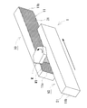
- FIG. 1 It is a schematic diagram which shows the use condition of the rolling die for thread components.
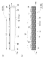
- the rolling part flat die for screw components is shown, (a) is a top view, (b) is a front view.
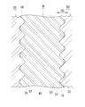
- It is a partially expanded longitudinal cross-sectional view which shows the rolling die for thread parts at the rolling start point at the time of processing, and a base material.
- It is a partially expanded longitudinal cross-sectional view which shows the rolling die for thread parts and the base material in the 1st boundary part at the time of processing.
- It is a partially expanded longitudinal cross-sectional view which shows the rolling die for thread components and the base material in the 2nd boundary part at the time of processing.
- the outline of the rolling flat die for screw parts concerning other embodiment is shown, (a) shows the outline of the section of the 1st partial biting surface, (b) shows the section of the 2nd partial biting surface An overview is shown.
- the rolling flat die 1 has a substantially rectangular fixed side die 10 fixed to a predetermined base, and a movable side die 50 that moves along the predetermined direction with respect to the fixed side die 10. And is composed of.
- the stationary die 10 has a stationary rolling surface 11
- the moving die 50 has a moving rolling surface 51.
- the base material W is disposed so that the fixed side rolling surface 11 and the moving side rolling surface 51 face each other, and the base material W sandwiched between the fixed side rolling surface 11 and the moving side rolling surface 51 is formed by rolling. It is processed to produce a bolt B.
- the moving direction of the moving side die 50 is a direction parallel to the fixed side rolling surface 11 of the fixed side die 10, and coincides with the rolling direction.
- each die 10, 50 in this embodiment are 60 mm in height, 400 mm in width, and 38.4 mm to 38 mm in depth. Moreover, what made the cold-die steel the said shape is used for each dice
- a high hardness material whose weight is reduced by heat-treating chromium molybdenum steel is adopted.
- a bolt B which is a screw part (product) is a M6 ⁇ 1.0 16R size hexagonal screw.
- a plurality of processing teeth 31 for forming the processed portion W1 of the base material W into a screw shape is provided on each of the rolled surfaces 11 and 51.
- the portion W1 to be processed of the base material W is plastically deformed by the processing teeth 31 and becomes the screw portion of the bolt B while the base material W rotates in the direction of the arrow shown in FIG.
- the processing teeth 31 form a valley bottom of the screw groove of the bolt B as described later.
- the pitch of the process tooth 31 in a present Example is set to the value equal to the pitch of the screw of the volt
- the rolling surfaces 11, 51 of the dies 10, 50 in the rolling flat die 1 have a biting surface 12. Furthermore, a finishing surface 13 is provided adjacent to the biting surface 12. Furthermore, a relief surface 14 is provided adjacent to the finish surface 13.
- a rolling start point 17 to which the base material W is supplied is defined in the bite surface 12, and rolling from one end 11a to the other end 11b of the dies 10, 50 with reference to the rolling start point 17
- the biting surface 12 has a slope which recedes as it goes away from the finishing surface 13. Such a gradient will be described in detail later, as it is part of the invention.
- the biting surface 12 is a second partial biting formed continuously between the first partial biting surface 15 and the first partial biting surface 15 and the finishing surface 13. And at least an abutment surface 16.
- the angle ⁇ of the first partial biting surface 15 and the angle ⁇ of the second partial biting surface 16 be ⁇ > ⁇ .
- the slope of the first partial bite surface 15 is at least the sum of the amount of drop (mm) in the first partial bite surface 15 and the amount of drop (mm) in the second partial bite surface 16. It is desirable to be configured with a drop amount (mm) of 60% or more.
- the slope of the second partial bite surface 16 is at least the sum of the amount of drop (mm) at the first partial bite surface 15 and the amount of drop (mm) at the second partial bite surface 16. It is desirable to be configured with a drop amount (mm) of 40% or less.
- the lengths L1, L2 and L3 described above have a relationship of L2> L1> L3.
- L1 130 mm
- L2 165 mm
- L3 92 mm.
- the mountain shape of the processing tooth 31 is changing to the mountain angle (60 degrees) of the processing tooth 31 of the finishing surface 13 sequentially from the root side.
- the height H of the processing tooth 31 (the distance from the valley bottom 33 to the apex 32 of the processing tooth 31), the height H1 of the processing tooth 31 of the first partial biting surface 15 and the second partial biting surface
- the height H3 of the sixteen processing teeth 31 and the height H2 of the processing teeth 31 of the finishing surface 13 satisfy H1 ⁇ H3 ⁇ H2.
- the shape of the processing teeth 31 in the finishing surface 13 and the relief surface 14 does not change in shape in that range, and has a shape corresponding to the thread groove shape in the bolt B.
- the moving side die 50 advances and the base material W reaches the first boundary portion 18 which is the boundary portion between the first partial biting surface 15 and the second partial biting surface 16, as shown in FIG. As shown, the threads are starting to rise.
- the desired shape of the bolt B is as shown in FIG. It is almost formed.
- the moving die 50 moves at a constant speed of about 900 mm / sec during a period from the base material W to the rolling surface 17 to the finish surface 13.
- the specific speed can be changed as appropriate, it is desirable to set a constant speed in the above period.
- the first partial biting surface 15 has a convex shape which is convex toward the moving side rolling surface 51.
- a configuration is proposed in which the second partial biting surface 16 has a concave surface shape which is concave with respect to the moving side rolling surface 51 as shown in FIG. 8B.
- the stationary side rolling surface 11 when the stationary side die 10 is cut along the imaginary line orthogonal to the rolling direction in the first partial biting surface 15 is convex toward the moving side rolling surface 51.
- the second partial bite surface 16 is formed of a concave curve curve which retracts to the fixed die 10 side.
- the first partial biting surface 15 has a concave surface shape corresponding to the stationary side rolling surface 11 in the moving side rolling surface 51 of the moving side die 50
- the partial biting surface 16 of 2 has a convex surface shape which is convex corresponding to the fixed side rolling surface 11.
- the first partial biting surface 15 has a concave surface shape which is concave with respect to the moving side rolling surface 51
- the second The partially biting surface 16 may have a convex surface shape which is convex toward the moving side rolling surface 51.
- the first partial biting surface 15 has a convex surface shape corresponding to the fixed side rolling surface 11 in the moving side rolling surface 51 of the moving side die 50.
- the second partially bite surface 16 has a concave surface shape which is concave corresponding to the fixed side rolling surface 11.
- the shape of the processing tooth 31 may be continuously changed so as to have a desired shape on the finishing surface 13.
- the mountain angle of the processed tooth 31 in the biting surface 12 is larger than the mountain angle of the processed tooth 31 in the finished surface 13, it is possible to appropriately change.
- biting surfaces 15 and 16 may be formed on the biting surface 12, but three or more partial biting surfaces may be formed.
- the length L1 of the first partial bite surface 15, the length L2 of the second partial bite surface 16, and the length L3 of the finish surface 13 are preferably L2> L1> L3, but L2 ⁇ L1. It may be L3. Further, the present invention does not actively exclude the configuration of L1> L2> L3.
- the moving speed of the moving-side die 50 moving at a constant speed is not limited to the above-mentioned speed, and can be freely set as appropriate in consideration of processing conditions such as materials and dimensions.
Landscapes
- Engineering & Computer Science (AREA)
- Mechanical Engineering (AREA)
- Forging (AREA)
- Extrusion Of Metal (AREA)
- Metal Rolling (AREA)
Abstract
長寿命化を図ることのできるネジ部品用転造平ダイス、及び該ネジ部品用転造平ダイスを用いた転造加工方法を提供する。 仕上げ面13に対して角度αの勾配を有する第1の部分食い付き面15と、第1の部分食い付き面15と仕上げ面13との間に形成され、仕上げ面13に対して角度βの勾配を有する第2の部分食い付き面16と、を具備し、第1の部分食い付き面15の転造始点17における加工歯31の山角度θ1が、前記仕上げ面13における加工歯31の山角度θ2よりも大であるため、ダイス10,50に加わる負荷を低減でき、転造平ダイス1の長寿命化を図ることができる。
Description
本発明は、雄ネジであるネジ部品を製造するためのネジ部品用転造平ダイス、及び該ダイスを用いた転造加工方法に関する。
例えば特許文献1には、高硬度の材料からなるボルトや雄ネジを転造加工によって製造するための転造ダイスが開示されている。
具体的には、食付き部における始点の加工歯は、仕上げ部の加工歯に比べて、その歯丈が低く且つ歯先角および当該始点の加工歯間の谷角が大きい転造ダイスが示されている。当該転造ダイスにあっては、当初に食付き部における始点の加工歯が浅く且つ鈍角形状で食い付くため、始点を含む食付き部の歯先付近で、亀裂や局部破壊を生じにくくなり、転造ダイスの長寿命化も可能となる。
また、特に近年、自動車等の軽量化が進んでおり、それらに用いられるボルトとしては、硬度が高い熱処理ボルトの需要が増加している。
しかしながら、こうした高硬度のボルトを従来のダイスで製造すると、ダイスにチッピング(欠け)が発生してしまったり、加工歯が変形してしまったりする不具合が早期に発生するため、ダイスの寿命が非常に短くなるという問題が生じる。
そこで本発明者らは、さらなる研鑽を続け、ダイス自体の製造コストを抑えつつ、高硬度の母材を転造加工しても長期にわたって使用できる長寿命のネジ部品用転造平ダイス、及び該ネジ部品用転造平ダイスを用いた転造加工方法の開発に成功した。
本発明は、ダイス自体の製造コストを抑えつつ、長期にわたって使用できるネジ部品用転造平ダイス、及び該ネジ部品用転造平ダイスを用いた転造加工方法を提供することを目的とする。
本発明は、ネジ部品となる母材が供給される食い付き面と、前記食い付き面に隣接して形成される仕上げ面とを少なくとも含む転造面を備えたネジ部品用転造平ダイスであって、前記食い付き面には、前記仕上げ面から離れる程後退する勾配を有し、仕上げ面に対する勾配の角度が角度αである第1の部分食い付き面と、前記第1の部分食い付き面と前記仕上げ面との間に連続状に形成され、前記仕上げ面から離れる程後退する勾配を有し、仕上げ面に対する勾配の角度が、前記角度αより小さい角度βである第2の部分食い付き面と、が少なくとも含まれており、前記第1の部分食い付き面と前記第2の部分食い付き面とにおいては、前記ネジ部品におけるネジ溝の谷底を形成する加工歯の山角度が、前記仕上げ面における加工歯の山角度よりも大であると共に、前記第1の部分食い付き面の始点から前記仕上げ面に向かうに従って、前記加工歯の山形状が、根元側から順に仕上げ面の加工歯の山角度に変化してなることを特徴とするネジ部品用転造平ダイスである。
かかる構成にあって、相対的に大きな角度の勾配を有する第1の部分食い付き面では、加工過程においていわゆる食い付きのスピードが相対的に速く、ダイスに対して負荷がかかりやすい。一方、母材が第1の部分食い付き面に位置している間は、仕上げ面の加工歯の山角度よりも大きい山角度の加工歯でこの母材を加工することになるため、肉の移動量が相対的に小さい。したがって、食い付きのスピードが相対的に速いものの、当該範囲では肉の移動量を相対的に小さくしているため、ダイスに対して過剰な負荷が発生することを抑制することができる。さらに、本発明は、加工歯の山角度が第1の部分食い付き面と同じであるが、仕上げ面に対する勾配角度が相対的に小さい第2の部分食い付き面を有している。かかる構成とすることにより、加工歯の山形状が最終形状に近づくことで肉の移動量が次第に増加していく過程でいわゆる食い付きのスピードが相対的に遅くなるため、十分な肉の移動量を確保しつつダイスにかかる負荷を和らげることができ、そして仕上げ面に母材を円滑に導入することができる。
なお、例えば第1の部分食い付き面における勾配の角度αと、第2の部分食い付き面における角度βとが、α<βであると、第2の部分食い付き面において肉の移動量が増加すると同時にいわゆる食い付きのスピードが速くなってしまい、結果、第2の部分食い付き面、あるいは第2の部分食い付き面と仕上げ面との境界部分でダイスに加わる負荷が急峻に増加して当該部分でチッピングが生じやすい。
ここで、前記第1の部分食い付き面における転造方向の長さL1と、前記第2の部分食い付き面における転造方向の長さL2と、前記仕上げ面における転造方向の長さL3とが、L2>L1>L3であることが望ましい。
かかる構成にあって、発明者による分析によれば、母材と転造面との間の摩擦が最も大きくなってダイスにかかる負荷が最大となる領域は、仕上げ面の直前の領域であることがわかってきた。そこで、かかる領域に対応する第2の部分食い付き面における長さL2をできる限り長く設定して、第2の部分食い付き面での加工域を最大とするようにした。そして、次いで第1の部分食い付き面における長さL1を設定し、最後に長さL1よりも小さい長さで仕上げ面を構成することにより、限られたダイスの全長のなかで効果的にダイスへの負荷を抑制した転造加工が可能となる。
また、第1の部分食い付き面における勾配は、前記第1の部分食い付き面における転造方向の長さと、前記第1の部分食い付き面における仕上げ面に対する落ち込み量とで構成され、第2の部分食い付き面における勾配は、前記第2の部分食い付き面における転造方向の長さと、仕上げ面に対する落ち込み量とで構成され、第2の部分食い付き面の勾配は、第1の部分食い付き面における落ち込み量と第2の部分食い付き面における落ち込み量との和に対して少なくとも40%以下の落ち込み量で構成されることが望ましい。
かかる構成とすることにより、第2の部分食い付き面、あるいは第2の部分食い付き面と仕上げ面との境界部分でダイスに加わる負荷が急峻に増加して当該部分でチッピングが生じてしまう、ということを回避できる。
また、本発明は、上記ネジ部品用転造平ダイスを用いた転造加工方法であって、前記ネジ部品用転造平ダイスのうち移動側のダイスは、母材が前記第1の部分食い付き面から前記仕上げ面にかけて通過する期間では定速移動することを特徴とする転造加工方法である。
かかる構成とすることによって、転造加工中に転造平ダイスの移動速度を変化させるような特別な工程を経ることなく、簡便でかつ安定して大量生産を行うことが可能となる。
本発明のネジ部品用転造平ダイスは、高硬度の母材に対してチッピング等の問題を招くことが抑制されるため、ダイスの長寿命化を図ることができる。
また本発明の転造加工方法は、簡便でかつ安定してネジ部品を大量生産することができる。
以下、本発明のネジ部品用転造平ダイス(以下、転造平ダイスという。)、及び該転造平ダイスを用いた転造加工方法を具体化した実施例を詳細に説明する。なお、本発明は、下記に示す実施例に限定されることはなく、適宜設計変更が可能である。なお、説明を明瞭とすべく、適宜図面において実際の寸法比率とは異なる寸法比率で示しているところがあるが、これにより本発明がその形状に限定して解釈されるものではない。
図1に示したように転造平ダイス1は、所定の基台に固定された略直方体形状の固定側ダイス10と、固定側ダイス10に対して所定方向に沿って移動する移動側ダイス50とによって構成されている。
さらに詳述すると、固定側ダイス10は固定側転造面11を有し、これに対して移動側ダイス50は移動側転造面51を有している。そして、固定側転造面11と移動側転造面51とが互いに向き合うように配置され、固定側転造面11と移動側転造面51との間に挟持された母材Wが転造加工されてボルトBが製造される。ところで、移動側ダイス50の移動方向は、固定側ダイス10の固定側転造面11に平行な方向であり、転造方向と一致する。
具体的に、図2に示すように、本実施例における各ダイス10,50の寸法は、高さが60mm、幅が400mm、及び奥行きが38.4mm~38mmである。また、各ダイス10,50は、冷間ダイス鋼を上記形状としたものが用いられている。
また、ボルトBの母材Wは、例えばクロムモリブデン鋼を熱処理することによって軽量化された高硬度の材料が採用されている。また、ネジ部品(製品)であるボルトBは、M6×1.0 16Rサイズの六角ネジである。
また、各転造面11,51には、母材Wの被加工部分W1をネジ形状とするための加工歯31が複数設けられている。そして、母材Wの被加工部分W1は、母材Wが図1に示した矢印の方向に回転しながら、加工歯31によって塑性変形されてボルトBのネジ部分となる。具体的に加工歯31は、後述するようにボルトBのネジ溝の谷底を形成することになる。
なお、本実施例における加工歯31のピッチは、各転造面11,51の全面にわたってボルトBのネジのピッチと等しい値に設定されている。
ところで、本実施例における固定側ダイス10及び移動側ダイス50は、同一形状を有し、各転造面11,51も点対称となるため、以下、転造面11,51の詳細については同じ符号を付して説明する。
図2(b)に示すように、転造平ダイス1におけるダイス10,50の転造面11,51は、食い付き面12を有している。さらに、この食い付き面12に隣接して仕上げ面13が設けられている。そしてさらに、仕上げ面13に隣接して逃がし面14が設けられている。
前記食い付き面12には、母材Wが供給される転造始点17が定められており、転造始点17を基準にしてダイス10,50の一端部11aから他端部11bに向かう転造方向に沿った長さL0が、L0=295mmとされている。なお、食い付き面12は、仕上げ面13から離れる程後退する勾配を有している。かかる勾配については、発明の要部にかかるため、後で詳述する。
また、前記仕上げ面12における転造方向に沿った長さL3は、L3=92mmとされている。
そして、前記逃がし面14における転造方向に沿う長さL4は、L4=13mmとされている。なお、逃がし面14は、仕上げ面13に対して勾配を有しており、仕上げ面13から離れるに従って転造面11,51が互いに離開する方向に開いている。具体的に、勾配の角度γは、γ=2.64°(0.6mm/13mm)とされている。
次に、食い付き面12の詳細について説明する。
図3に示すように、食い付き面12は、第1の部分食い付き面15と、第1の部分食い付き面15と仕上げ面13との間に連続状に形成された第2の部分食い付き面16とを少なくとも具備している。
第1の部分食い付き面15は、転造方向に沿う長さL1が、L1=150mmとされている。また、仕上げ面13に対して角度α=0.0955°(0.25/150)の勾配を有している。換言すれば、長さL1(150mm)に対して後退する落ち込み量が、0.25mmとされている。
これに対し、第2の部分食い付き面16は、転造方向に沿う長さL2が、L2=145mmとされている。また、仕上げ面13に対して角度β=0.0277°(0.07/145)の勾配を有している。換言すれば、長さL2(145mm)に対して後退する落ち込み量が、0.07mmとされている。
すなわち、第1の部分食い付き面15の角度α及び第2の部分食い付き面16の角度βは、α>βであることが望ましい。また、第1の部分食い付き面15の勾配は、第1の部分食い付き面15における落ち込み量(mm)と第2の部分食い付き面16における落ち込み量(mm)との和に対して少なくとも60%以上の落ち込み量(mm)で構成されることが望ましい。また、第2の部分食い付き面16の勾配は、第1の部分食い付き面15における落ち込み量(mm)と第2の部分食い付き面16における落ち込み量(mm)との和に対して少なくとも40%以下の落ち込み量(mm)で構成されることが望ましい。
また、特に望ましくは、上記した長さL1,L2,L3は、L2>L1>L3の関係である。例えば、L1=130mm、L2=165mm、L3=92mmとすることができる。
次に、第1の部分食い付き面15と第2の部分食い付き面16の各加工歯31について説明する。
第1の部分食い付き面15では、ダイス10,50の一端部11aから5mmだけ離れた位置に転造始点17が設定されている。そして、この転造始点17における加工歯31は、図4,図7(a)に示したように、山角度θ1がθ1=80°である。
また、図5,図7(b)に示したように、第1の部分食い付き面15と、第2の部分食い付き面16との境界部分における加工歯31は、山角度θ1がθ1=80°である。また、加工歯31の山形状は、根元側から順に仕上げ面13の加工歯31の山角度(60°)に変化している。
一方、図6,図7(c)に示したように、仕上げ面13における加工歯31の山角度θ2はθ2=60°である。
そして、加工歯31の高さH(加工歯31の谷底33から頂点32までの距離)について、第1の部分食い付き面15の加工歯31の高さH1と、第2の部分食い付き面16の加工歯31の高さH3と、仕上げ面13の加工歯31の高さH2とは、H1<H3<H2となっている。
なお、仕上げ面13及び前記逃がし面14における加工歯31の形状は、その範囲で形状変化がなく、ボルトBにおけるネジ溝形状に対応した形状を有している。
次に、母材Wの加工過程を以下に詳述する。
まず、図4に示したように、転造始点17に母材Wが位置するときは、母材Wの被加工部分W1は塑性変形が開始されていない。
そして、移動側ダイス50が移動し始めると、第1の部分食い付き面15の加工歯31によって母材Wが加工開始される。
さらに、移動側ダイス50が進行し、母材Wが、第1の部分食い付き面15と第2の部分食い付き面16との境界部である第1境界部18に達するときには、図5に示すように、ネジ山が立ち上がり始めている。
そしてさらに、母材Wが、第2の部分食い付き面16と仕上げ面13との境界部である第2境界部19に至ると、図6に示したように、所望のボルトBの形状がほぼ形成される。
その後、ボルトBは逃がし面14に至り、転造加工が終了する。
ここで、移動側ダイス50は、母材Wが転造始点17から仕上げ面13に至るまでの期間は、約900mm/秒の速度で定速移動する。具体的な速度は適宜変更できるが、前記期間で一定速度に定めることが望ましい。
また、他の実施形態が提案される。
図8(a)に示すように、固定側ダイス10における固定側転造面11にあって、第1の部分食い付き面15は、移動側転造面51に向かって凸状となる凸状面形状とし、図8(b)に示すように、第2の部分食い付き面16は、移動側転造面51に対して凹状となる凹状面形状とする構成が提案される。換言すれば、第1の部分食い付き面15において転造方向に直交する仮想線に沿って固定側ダイス10を切断したときの固定側転造面11が移動側転造面51に向かって凸状のカーブ曲線で構成され、第2の部分食い付き面16においては固定側ダイス10側に退避する凹状のカーブ曲線で構成される。なお、かかる場合は、移動側ダイス50における移動側転造面51にあって、第1の部分食い付き面15は、固定側転造面11に対応して凹状となる凹状面形状となり、第2の部分食い付き面16は、固定側転造面11に対応して凸状となる凸状面形状となる。
図8(a)に示すように、固定側ダイス10における固定側転造面11にあって、第1の部分食い付き面15は、移動側転造面51に向かって凸状となる凸状面形状とし、図8(b)に示すように、第2の部分食い付き面16は、移動側転造面51に対して凹状となる凹状面形状とする構成が提案される。換言すれば、第1の部分食い付き面15において転造方向に直交する仮想線に沿って固定側ダイス10を切断したときの固定側転造面11が移動側転造面51に向かって凸状のカーブ曲線で構成され、第2の部分食い付き面16においては固定側ダイス10側に退避する凹状のカーブ曲線で構成される。なお、かかる場合は、移動側ダイス50における移動側転造面51にあって、第1の部分食い付き面15は、固定側転造面11に対応して凹状となる凹状面形状となり、第2の部分食い付き面16は、固定側転造面11に対応して凸状となる凸状面形状となる。
また、同様に、固定側ダイス10における固定側転造面11にあって、第1の部分食い付き面15は、移動側転造面51に対して凹状となる凹状面形状とし、第2の部分食い付き面16は、移動側転造面51に向かって凸状となる凸状面形状とする構成としてもよい。なお、かかる場合は、移動側ダイス50における移動側転造面51にあって、第1の部分食い付き面15は、固定側転造面11に対応して凸状となる凸状面形状となり、第2の部分食い付き面16は、固定側転造面11に対応して凹状となる凹状面形状となる。
本発明は上記実施例に限定されるものではなく、例えば加工歯31の形状は、仕上げ面13において所望の形状となるように連続して変化していればよい。例えば、仕上げ面13における加工歯31の山角度よりも、食い付き面12における加工歯31の山角度が大きいという条件下であれば、適宜変更可能である。
また、食い付き面12には、2つの部分食い付き面15,16を形成するだけでなく、3以上の部分食い付き面を形成するようにしてもよい。
また、第1の部分食い付き面15の長さL1、第2の部分食い付き面16の長さL2、及び仕上げ面13の長さL3は、L2>L1>L3が望ましいが、L2≧L1>L3であってもよい。また、本発明は、L1>L2>L3の構成を積極的に排除するものではない。
また、定速移動する移動側ダイス50の移動速度は、上記速度に限定されず、材料や寸法等の加工条件等を考慮して適宜自由に設定可能である。
また、いわゆる1WAYダイスや2WAYダイスについても適用可能である。
1 転造平ダイス
10 固定側ダイス
11,51 転造面
12 食い付き面
13 仕上げ面
15 第1の部分食い付き面
16 第2の部分食い付き面
31 加工歯
50 移動側ダイス
α 第1の部分食い付き面の勾配角度
β 第2の部分食い付き面の勾配角度
L1 第1の部分食い付き面の長さ
L2 第2の部分食い付き面の長さ
L3 仕上げ面の長さ
θ1~θ3 山角度
B ボルト(ネジ部品)
W 母材
10 固定側ダイス
11,51 転造面
12 食い付き面
13 仕上げ面
15 第1の部分食い付き面
16 第2の部分食い付き面
31 加工歯
50 移動側ダイス
α 第1の部分食い付き面の勾配角度
β 第2の部分食い付き面の勾配角度
L1 第1の部分食い付き面の長さ
L2 第2の部分食い付き面の長さ
L3 仕上げ面の長さ
θ1~θ3 山角度
B ボルト(ネジ部品)
W 母材
Claims (4)
- ネジ部品となる母材が供給される食い付き面と、前記食い付き面に隣接して形成される仕上げ面とを少なくとも含む転造面を備えたネジ部品用転造平ダイスであって、
前記食い付き面には、
前記仕上げ面から離れる程後退する勾配を有し、仕上げ面に対する勾配の角度が角度αである第1の部分食い付き面と、
前記第1の部分食い付き面と前記仕上げ面との間に連続状に形成され、前記仕上げ面から離れる程後退する勾配を有し、仕上げ面に対する勾配の角度が、前記角度αより小さい角度βである第2の部分食い付き面と、
が少なくとも含まれており、
前記第1の部分食い付き面と前記第2の部分食い付き面とにおいては、前記ネジ部品におけるネジ溝の谷底を形成する加工歯の山角度が、前記仕上げ面における加工歯の山角度よりも大であると共に、
前記第1の部分食い付き面の始点から前記仕上げ面に向かうに従って、前記加工歯の山形状が、根元側から順に仕上げ面の加工歯の山角度に変化してなる
ことを特徴とするネジ部品用転造平ダイス。 - 前記第1の部分食い付き面における転造方向の長さL1と、
前記第2の部分食い付き面における転造方向の長さL2と、
前記仕上げ面における転造方向の長さL3とが、
L2>L1>L3
である請求項1に記載のネジ部品用転造平ダイス。 - 第1の部分食い付き面における勾配は、前記第1の部分食い付き面における転造方向の長さと、前記第1の部分食い付き面における仕上げ面に対する落ち込み量とで構成され、
第2の部分食い付き面における勾配は、前記第2の部分食い付き面における転造方向の長さと、仕上げ面に対する落ち込み量とで構成され、
第2の部分食い付き面の勾配は、第1の部分食い付き面における落ち込み量と第2の部分食い付き面における落ち込み量との和に対して少なくとも40%以下の落ち込み量で構成される
請求項1又は請求項2に記載のネジ部品用転造平ダイス。 - 請求項1乃至請求項3のいずれか1項に記載のネジ部品用転造平ダイスを用いた転造加工方法であって、
前記ネジ部品用転造平ダイスのうち移動側のダイスは、母材が前記第1の部分食い付き面から前記仕上げ面にかけて通過する期間では定速移動する
ことを特徴とする転造加工方法。
Priority Applications (4)
| Application Number | Priority Date | Filing Date | Title |
|---|---|---|---|
| KR1020167027905A KR101789730B1 (ko) | 2016-03-18 | 2016-04-27 | 나사 부품용 전조 평다이스, 및 전조 가공 방법 |
| US15/567,968 US10118214B2 (en) | 2016-03-18 | 2016-04-27 | Thread-rolling flat die for threaded fastener, and thread-rolling method |
| CN201680002074.6A CN107530763B (zh) | 2016-03-18 | 2016-04-27 | 螺纹零件用搓丝板以及滚轧加工方法 |
| EP16894471.8A EP3263244B1 (en) | 2016-03-18 | 2016-04-27 | Rolling flat die for screw component and rolling working method |
Applications Claiming Priority (2)
| Application Number | Priority Date | Filing Date | Title |
|---|---|---|---|
| JP2016056233A JP5979806B1 (ja) | 2016-03-18 | 2016-03-18 | ネジ部品用転造平ダイス、及び転造加工方法 |
| JP2016-056233 | 2016-03-18 |
Publications (1)
| Publication Number | Publication Date |
|---|---|
| WO2017158853A1 true WO2017158853A1 (ja) | 2017-09-21 |
Family
ID=56820009
Family Applications (1)
| Application Number | Title | Priority Date | Filing Date |
|---|---|---|---|
| PCT/JP2016/063159 Ceased WO2017158853A1 (ja) | 2016-03-18 | 2016-04-27 | ネジ部品用転造平ダイス、及び転造加工方法 |
Country Status (7)
| Country | Link |
|---|---|
| US (1) | US10118214B2 (ja) |
| EP (1) | EP3263244B1 (ja) |
| JP (1) | JP5979806B1 (ja) |
| KR (1) | KR101789730B1 (ja) |
| CN (1) | CN107530763B (ja) |
| TW (1) | TWI595941B (ja) |
| WO (1) | WO2017158853A1 (ja) |
Cited By (1)
| Publication number | Priority date | Publication date | Assignee | Title |
|---|---|---|---|---|
| WO2020003530A1 (ja) * | 2018-06-29 | 2020-01-02 | 日東精工株式会社 | 平ダイス |
Families Citing this family (4)
| Publication number | Priority date | Publication date | Assignee | Title |
|---|---|---|---|---|
| TWI678267B (zh) * | 2018-09-06 | 2019-12-01 | 川恆技術研究工業股份有限公司 | 工具製造方法 |
| JP7116860B2 (ja) * | 2020-03-26 | 2022-08-10 | オーエスジー株式会社 | 転造ダイス及びその製造方法 |
| IT202000032609A1 (it) * | 2020-12-29 | 2022-06-29 | F Lli Mauri Spa | Coppia di utensili di rullatura di tiranti cilindrici e procedimento di rullatura tramite detti utensili |
| KR102556379B1 (ko) * | 2021-11-18 | 2023-07-17 | 주식회사 선일다이파스 | 볼트 가공용 전조 다이스 |
Citations (4)
| Publication number | Priority date | Publication date | Assignee | Title |
|---|---|---|---|---|
| JPH0386343A (ja) * | 1989-08-28 | 1991-04-11 | Sps Technol Inc | ねじ転造ダイス |
| JPH05245573A (ja) * | 1991-09-17 | 1993-09-24 | Quamco Inc | ねじ形成方法及び装置 |
| JP2002192282A (ja) * | 2000-10-13 | 2002-07-10 | Nachi Fujikoshi Corp | 転造平ダイス及び転造加工方法 |
| JP2005288456A (ja) | 2004-03-31 | 2005-10-20 | Sanmei Seisakusho:Kk | 転造ダイス |
Family Cites Families (12)
| Publication number | Priority date | Publication date | Assignee | Title |
|---|---|---|---|---|
| GB581249A (en) * | 1944-07-15 | 1946-10-07 | Harold Morris | Improvements in or relating to dies for rolling screw threads, serrations and the like |
| US3260100A (en) * | 1963-07-30 | 1966-07-12 | Illinois Tool Works | Apparatus for simultaneously imparting an alternate series of thread forms on a workpiece |
| SU721208A1 (ru) * | 1977-04-11 | 1980-03-15 | Физико-технический институт АН Белорусской ССР | Рейка дл накатывани зубчатых колес |
| US4362045A (en) * | 1980-10-10 | 1982-12-07 | Ex-Cell-O Corporation | Tooth forming tools |
| US4488418A (en) * | 1982-03-11 | 1984-12-18 | Ex-Cell-O Corporation | Apparatus for roll sizing diameters |
| US4798070A (en) * | 1983-07-01 | 1989-01-17 | Colt Industries Operating Corporation | Combined thread rolling dies |
| US4862718A (en) * | 1988-07-14 | 1989-09-05 | Sps Technologies, Inc. | Thread rolling dies |
| CN1046299A (zh) * | 1989-04-14 | 1990-10-24 | 顿河罗斯托夫农业机械制造研究所 | 螺纹滚压用工具 |
| US5182937A (en) * | 1991-09-17 | 1993-02-02 | Quamco, Inc. | Seam-free thread rolling dies |
| JPH10146635A (ja) * | 1996-11-13 | 1998-06-02 | Toyota Motor Corp | 軸部材の外歯転造装置 |
| JP4215324B2 (ja) | 1998-12-15 | 2009-01-28 | レッキス工業株式会社 | 薄肉鋼管用ねじ転造ローラ |
| US6598453B2 (en) | 2000-10-13 | 2003-07-29 | Nachi-Fujikoshi Corp. | Tooth rolling flat dies and method for forming teeth |
-
2016
- 2016-03-18 JP JP2016056233A patent/JP5979806B1/ja active Active
- 2016-04-27 EP EP16894471.8A patent/EP3263244B1/en active Active
- 2016-04-27 CN CN201680002074.6A patent/CN107530763B/zh active Active
- 2016-04-27 US US15/567,968 patent/US10118214B2/en active Active
- 2016-04-27 KR KR1020167027905A patent/KR101789730B1/ko active Active
- 2016-04-27 WO PCT/JP2016/063159 patent/WO2017158853A1/ja not_active Ceased
- 2016-05-17 TW TW105115152A patent/TWI595941B/zh active
Patent Citations (4)
| Publication number | Priority date | Publication date | Assignee | Title |
|---|---|---|---|---|
| JPH0386343A (ja) * | 1989-08-28 | 1991-04-11 | Sps Technol Inc | ねじ転造ダイス |
| JPH05245573A (ja) * | 1991-09-17 | 1993-09-24 | Quamco Inc | ねじ形成方法及び装置 |
| JP2002192282A (ja) * | 2000-10-13 | 2002-07-10 | Nachi Fujikoshi Corp | 転造平ダイス及び転造加工方法 |
| JP2005288456A (ja) | 2004-03-31 | 2005-10-20 | Sanmei Seisakusho:Kk | 転造ダイス |
Non-Patent Citations (1)
| Title |
|---|
| See also references of EP3263244A4 |
Cited By (2)
| Publication number | Priority date | Publication date | Assignee | Title |
|---|---|---|---|---|
| WO2020003530A1 (ja) * | 2018-06-29 | 2020-01-02 | 日東精工株式会社 | 平ダイス |
| TWI766157B (zh) * | 2018-06-29 | 2022-06-01 | 日商日東精工股份有限公司 | 平模 |
Also Published As
| Publication number | Publication date |
|---|---|
| CN107530763A (zh) | 2018-01-02 |
| EP3263244A4 (en) | 2018-12-26 |
| US20180117664A1 (en) | 2018-05-03 |
| EP3263244B1 (en) | 2022-05-11 |
| CN107530763B (zh) | 2020-06-05 |
| JP2017170455A (ja) | 2017-09-28 |
| JP5979806B1 (ja) | 2016-08-31 |
| EP3263244A1 (en) | 2018-01-03 |
| TW201733705A (zh) | 2017-10-01 |
| KR101789730B1 (ko) | 2017-10-25 |
| TWI595941B (zh) | 2017-08-21 |
| US10118214B2 (en) | 2018-11-06 |
Similar Documents
| Publication | Publication Date | Title |
|---|---|---|
| JP5979806B1 (ja) | ネジ部品用転造平ダイス、及び転造加工方法 | |
| KR101277383B1 (ko) | 전조다이스 | |
| JP4804167B2 (ja) | 転造工具及びねじ又はウォームと少数歯スプラインとの同時転造方法 | |
| JP5302947B2 (ja) | 転造ダイス | |
| JP3604325B2 (ja) | 棒先付きねじ用転造ダイス | |
| JP4875588B2 (ja) | 丸棒材の鍛造方法 | |
| KR20120131020A (ko) | 나사전조탭 | |
| JP5465955B2 (ja) | 転造平ダイス | |
| JP2005288456A (ja) | 転造ダイス | |
| JP6894592B2 (ja) | 自穿孔ねじの転造ダイス | |
| JP4145716B2 (ja) | 深溝付きスクリュウの転造ダイスと深溝付きスクリュウの製造方法 | |
| JP2006187796A (ja) | 転造ダイス、及び、転造ダイスの製造方法 | |
| JP4827562B2 (ja) | 転造ダイスの製造方法 | |
| JP6716514B2 (ja) | 転造ダイス | |
| KR101606116B1 (ko) | 다단 기어의 전조 다이스 | |
| JP3960845B2 (ja) | 深溝付きスクリュウの転造ダイスと深溝付きスクリュウの製造方法 | |
| JP2019010665A (ja) | ドリルねじの転造ダイス | |
| JP6641694B2 (ja) | 内歯ヘリカルギア製造用金型、内歯ヘリカルギアの製造方法、及び、内歯ヘリカルギア製造用ギアブランク | |
| JP2007283361A (ja) | 転造工具 | |
| JP4266631B2 (ja) | 転造平ダイス | |
| JP6201078B1 (ja) | 曲がり矯正用転造ダイス、棒材の曲がり矯正方法、及び棒材の製造方法 | |
| RU54840U1 (ru) | Инструмент для накатки резьбы на путевых шурупах | |
| RU2354487C1 (ru) | Инструмент для накатывания резьбы | |
| JP2017029998A (ja) | 転造ダイス | |
| JP2007283390A (ja) | 転造平ダイス、転造平ダイスの製造方法及び転造方法 |
Legal Events
| Date | Code | Title | Description |
|---|---|---|---|
| WWE | Wipo information: entry into national phase |
Ref document number: 15567968 Country of ref document: US |
|
| NENP | Non-entry into the national phase |
Ref country code: DE |