WO2017159415A1 - 印刷版 - Google Patents
印刷版 Download PDFInfo
- Publication number
- WO2017159415A1 WO2017159415A1 PCT/JP2017/008646 JP2017008646W WO2017159415A1 WO 2017159415 A1 WO2017159415 A1 WO 2017159415A1 JP 2017008646 W JP2017008646 W JP 2017008646W WO 2017159415 A1 WO2017159415 A1 WO 2017159415A1
- Authority
- WO
- WIPO (PCT)
- Prior art keywords
- printing
- protrusions
- distribution density
- central region
- direction portion
- Prior art date
- Legal status (The legal status is an assumption and is not a legal conclusion. Google has not performed a legal analysis and makes no representation as to the accuracy of the status listed.)
- Ceased
Links
Images



Classifications
-
- B—PERFORMING OPERATIONS; TRANSPORTING
- B41—PRINTING; LINING MACHINES; TYPEWRITERS; STAMPS
- B41N—PRINTING PLATES OR FOILS; MATERIALS FOR SURFACES USED IN PRINTING MACHINES FOR PRINTING, INKING, DAMPING, OR THE LIKE; PREPARING SUCH SURFACES FOR USE AND CONSERVING THEM
- B41N1/00—Printing plates or foils; Materials therefor
- B41N1/12—Printing plates or foils; Materials therefor non-metallic other than stone, e.g. printing plates or foils comprising inorganic materials in an organic matrix
-
- B—PERFORMING OPERATIONS; TRANSPORTING
- B41—PRINTING; LINING MACHINES; TYPEWRITERS; STAMPS
- B41M—PRINTING, DUPLICATING, MARKING, OR COPYING PROCESSES; COLOUR PRINTING
- B41M1/00—Inking and printing with a printer's forme
- B41M1/02—Letterpress printing, e.g. book printing
- B41M1/04—Flexographic printing
-
- B—PERFORMING OPERATIONS; TRANSPORTING
- B41—PRINTING; LINING MACHINES; TYPEWRITERS; STAMPS
- B41N—PRINTING PLATES OR FOILS; MATERIALS FOR SURFACES USED IN PRINTING MACHINES FOR PRINTING, INKING, DAMPING, OR THE LIKE; PREPARING SUCH SURFACES FOR USE AND CONSERVING THEM
- B41N1/00—Printing plates or foils; Materials therefor
- B41N1/16—Curved printing plates, especially cylinders
- B41N1/22—Curved printing plates, especially cylinders made of other substances
-
- G—PHYSICS
- G03—PHOTOGRAPHY; CINEMATOGRAPHY; ANALOGOUS TECHNIQUES USING WAVES OTHER THAN OPTICAL WAVES; ELECTROGRAPHY; HOLOGRAPHY
- G03F—PHOTOMECHANICAL PRODUCTION OF TEXTURED OR PATTERNED SURFACES, e.g. FOR PRINTING, FOR PROCESSING OF SEMICONDUCTOR DEVICES; MATERIALS THEREFOR; ORIGINALS THEREFOR; APPARATUS SPECIALLY ADAPTED THEREFOR
- G03F7/00—Photomechanical, e.g. photolithographic, production of textured or patterned surfaces, e.g. printing surfaces; Materials therefor, e.g. comprising photoresists; Apparatus specially adapted therefor
Definitions
- the present invention relates to a printing plate used for printing such as flexographic printing.
- Flexographic printing is generally performed by a printing machine as shown in FIG.
- This printing machine includes a cylindrical plate cylinder 51 on which a printing plate P1 is mounted, an anilox roll 52 for attaching ink to the printing plate P1, an ink supply device 53 for supplying ink to the surface of the anilox roll 52, A doctor 54 that removes excess ink on the surface of the anilox roll 52 and a printing stage 55 on which a printing medium Q to be printed is placed are provided.
- flexographic printing by the above printing press is performed as follows. That is, the printing plate P1 is mounted on the peripheral side surface of the plate cylinder 51, and the ink supplied from the ink supply device 53 is rotated to the printing area of the printing plate P1 via the anilox roll 52 while rotating the plate cylinder 51. Printing is performed by adhering and transferring the adhering ink to a printing medium Q such as a glass substrate placed on the printing stage 55. At this time, the printing stage 55 is slid in synchronization with the rotation of the plate cylinder 51.
- the printing plate P1 is generally shown in a plan view in FIG. 4 (a), and in a plan view of FIG. 4 (b) in a TT cross section of FIG. 4 (a). , And a printing convex portion 12 formed at the center of the surface of the base portion 11.
- the printing convex portion 12 is the printing area, and the portion of the base portion 11 around the printing convex portion 12 does not participate in printing.
- FIG. 4C with an enlarged cross-sectional view of the main part of FIG. 4B, a plurality of protrusions 13 are formed on the top surface of the printing convex portion 12 with a gap 14 therebetween. Ink is held in the gap 14.
- the printing plate P1 is flexible so that it can be mounted on the peripheral side surface of the plate cylinder 51 (see FIG. 3).
- the printing convex portion 12 of the printing plate P1 is in contact with the anilox roll 52 and the printing medium Q, and is thus held by the printing convex portion 12 by the pressure at the time of contact.
- the ink gathers in the peripheral region 12D of the printing convex portion 12. Therefore, a so-called “marginal phenomenon” occurs in which the thickness of the printed film formed by the flexographic printing becomes thicker at the peripheral portion surrounding the central portion than at the central portion.
- the present applicant makes the distribution density of the protrusions 13 formed on the printing convex portion 12 higher in the peripheral region 12D than in the central region 12A of the printing convex portion 12.
- a set printing plate is proposed and applied (for example, see Patent Documents 1 and 2). That is, in the peripheral region 12D of the printing convex portion 12, by increasing the distribution density of the protrusions 13, the gaps 14 between the protrusions 13 are reduced so that the amount of ink held in the gaps 14 is reduced. Yes. Thereby, it is suppressed that the thickness of the peripheral part of a printing film becomes thick.
- the distribution density of the protrusions 13 in the peripheral region 12D of the printing convex portion 12 is the same as the printing direction portion 12B along the printing direction (rotating direction of the plate cylinder 51).
- the right-angled portion 12C along the right-angle direction is set to be the same.
- the thickness of the peripheral portion of the printing film may be increased depending on the case, and there is room for improvement in that respect.
- the present invention has been made in view of such circumstances, and provides a printing plate capable of stably suppressing the occurrence of a marginal phenomenon.
- the printing plate of the present invention includes a printing convex portion in which a plurality of protrusions are distributed on the top surface, and the top surface of the printing convex portion is a central region and a peripheral region adjacent to the peripheral edge of the central region.
- the peripheral area has a printing direction portion along the printing direction and a perpendicular direction portion along a right angle direction perpendicular to the printing direction, and the distribution density of the protrusions is
- the central region, the printing direction portion, and the perpendicular direction portion are different from each other, and among these distribution densities, the distribution density in the perpendicular direction portion is set to be the highest, and in the printing direction portion, The distribution density is set to be the lowest.
- the present inventor conducted researches focusing on the distribution density of a plurality of protrusions distributed on the top surface of the printing convex portion of the printing plate in order to stably suppress the occurrence of the marginal phenomenon.
- the distribution density of the protrusions is set to be different between the central region of the printing convex portion, the printing direction portion, and the perpendicular direction portion, and the distribution direction has the right angle direction. It has been found that the marginal phenomenon can be stably suppressed by setting the distribution density at the highest part and setting the distribution density at the lowest part in the printing direction.
- the printing convex portions are formed. It is presumed that the ink held on the printing convex portion is likely to spread to a uniform thickness on the top surface of the printing convex portion due to the pressure when contacting the anilox roll of the printing press and the printing medium.
- the distribution density of the protrusions is different between the central region of the printing convex portion and the peripheral portion in the printing direction portion and the perpendicular direction portion.
- the distribution density in the perpendicular direction portion is set to the highest, and the distribution density in the print direction portion is set to the lowest.
- the ink held by the printing convex portion has a uniform thickness on the top surface of the printing convex portion due to the pressure when the printing convex portion is in contact with the anilox roll of the printing press and the printing medium. It becomes easy to spread. As a result, the occurrence of a marginal phenomenon can be stably suppressed, and the thickness uniformity of the printed film can be improved.
- the ratio (M C / M A ) of the projection distribution density (M C ) in the perpendicular portion to the projection distribution density (M A ) in the central region is set to 1.25.
- the improvement in the uniformity of the thickness of the printed film is remarkable.
- a ratio (N C / N A ) of the occupation area ratio (N C ) of the protrusions in the perpendicular portion to the occupation area ratio (N A ) of the protrusions in the central region is set to 0.8.
- the distribution density of the protrusions can be made more appropriate, and the thickness uniformity of the printed film can be further improved.
- the ratio (N B / N A ) of the occupation area ratio (N B ) of the projections in the printing direction portion to the occupation area ratio (N A ) of the projections in the central region is set to 0.95. Also in this case, the distribution density of the protrusions can be made more appropriate, and the thickness uniformity of the printed film can be further improved.
- FIG. 1 schematically shows an embodiment of a printing plate of the present invention, in which (a) is a plan view of the printing plate, and (b) is an enlarged view of a principal part in the RR cross section of (a).
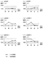
- FIG. 4C is an enlarged view of a main part in the SS section of FIG. (A)-(f) is a graph which shows the thickness of the printing film of an Example, a prior art example, and Comparative Examples 1-4. It is explanatory drawing which shows typically the printing machine using the said printing plate.
- a conventional printing plate is schematically shown, wherein (a) is a plan view of the printing plate, (b) is a TT cross-sectional view of (a), and (c) is a drawing of (b).
- FIG. 1 (a) is a plan view showing an embodiment of a printing plate of the present invention
- FIG. 1 (b) is an enlarged view of an essential part of the RR section of FIG. 1 (a).
- 1 (c) is an enlarged view of a main part of the SS cross section of FIG. 1 (a).
- the printing plate P according to this embodiment includes a flat plate-like base portion 1 having a rectangular shape in plan view, and a printing convex portion 2 having a rectangular shape in plan view formed at the center of the surface of the base portion 1.
- a plurality of frustoconical minute protrusions 3 are distributed and formed on the top surface of the convex portion 2 with a gap 4.
- the base 1, the printing convex portion 2, and the protrusion 3 are integrally formed.
- the direction of the arrow X along the long side of the printing convex portion 2 that is rectangular in plan view is set as the printing direction.
- the printing convex portion 2 is divided into three regions (portions) 2A to 2C according to the distribution density of the protrusions 3.
- the three regions (portions) 2A to 2C are a central region 2A of the printing convex portion 2 and a peripheral portion adjacent to the peripheral portion of the central region 2A. It is a perpendicular portion 2C along a perpendicular direction perpendicular to the printing direction.
- the four corner portions of the printing convex portion 2 where the printing direction portion 2B and the perpendicular direction portion 2C overlap are included in the perpendicular direction portion 2C.
- the distribution density in the perpendicular direction portion 2C is the highest, the next highest is the central region 2A, and the lowest is the printing direction portion 2B.
- the distribution density of the projections 3 is, for example, the number of the projections 3 per inch (25.4 mm), and is the highest in the range of 400 to 600 / inch at the highest perpendicular portion 2C and the next higher center.
- the area 2A is set within the range of 300 to 500 / inch
- the lowest printing direction portion 2B is set within the range of 200 to 400 / inch.
- the ratio (M C / M A ) of the distribution density (M C ) of the protrusions 3 in the perpendicular direction portion 2C to the distribution density (M A ) of the protrusions 3 in the central region 2A is 1.25, and the printing
- the ratio (M B / M A ) of the distribution density (M B ) of the protrusions 3 in the directional portion 2B to the distribution density (M A ) of the protrusions 3 in the central region 2A is set to 0.75. .
- the occupation area ratio of the protrusion 3 is also different in the three areas (parts) 2A to 2C, and the order of the height of the occupation area ratio is that of the central area 2A.
- the highest, next highest is the printing direction portion 2B, and the lowest is the perpendicular direction portion 2C.
- the occupation area ratio of the protrusion 3 is a ratio of the total area of the bottom of the protrusion 3 to the area of the top surface of the printing convex portion 2.
- the occupation area ratio of the projection 3 is, for example, in the range of 40 to 50% in the highest central region 2A, in the range of 38 to 48% in the next higher print direction portion 2B, and in the lowest perpendicular direction.
- the ratio (N C / N A ) of the occupation area ratio (N C ) of the protrusion 3 in the perpendicular portion 2C to the occupation area ratio (N A ) of the protrusion 3 in the central region 2A is 0.8.
- the ratio (N B / N A ) of the occupation area ratio (N B ) of the protrusions 3 in the printing direction portion 2B to the occupation area ratio (N A ) of the protrusions 3 in the central region 2A is set to 0.95. It is to be done.
- the depth of the projection 3 (depth from the top surface of the projection 3 to the top surface of the printing convex portion 2) D is also the three regions (portions) 2A to 2C.
- the order of the magnitude of the depth D is opposite to the order of the distribution density. That is, the printing direction portion 2B is the largest, the next largest is the central region 2A, and the smallest is the perpendicular direction portion 2C.
- the depth D of the projection 3 is, for example, within a range of 15 to 25 ⁇ m at the largest printing direction portion 2B, within a range of 10 to 20 ⁇ m at the next largest central region 2A, and from 5 to 5 at the smallest perpendicular direction portion 2C. It is set within the range of 15 ⁇ m.
- the dimensions and the formation pitch of the protrusions 3 are uniform. Therefore, in each of the three regions (parts) 2A to 2C, the distribution density, occupation area ratio, and depth D of the protrusions 3 are uniform.
- a region where the printing convex portion 2 is formed is a printing region, and the outer dimension of the top surface of the printing convex portion 2 is set to the outer dimension of the printed film to be printed.
- the width W B of the printing convex portion 2 of the printing direction portion 2B is 1.2-2 length of the vertical of the top surface of the printing convex portion 2 (length of the perpendicular sides to the printing direction).
- the width W C of the perpendicular portion 2C is set within a range of 2%, and the width W C of the lateral portion of the top surface of the printing convex portion 2 (the length of the side along the printing direction) is 1.2 to 2 Set within the range of 2%.
- the dimensions of the frustoconical protrusions 3 are, for example, such that the top surface diameter is in the range of 20 to 70 ⁇ m, the bottom surface diameter is in the range of 185 to 300% of the top surface diameter, and the depth D is 5 to 25 ⁇ m. In this range, the formation pitch is set in the range of 51 to 85 ⁇ m.
- the printing plate P is used for flexographic printing and has flexibility so that it can be mounted on the peripheral side surface of the plate cylinder 51 of a printing press (see FIG. 3).
- Examples of the material for forming the printing plate P include resin and rubber.
- Examples of a method for forming the printing plate P include mold forming. In particular, when a photosensitive resin is used as a forming material, the printing plate P can be formed by a photolithography method.
- a printing film such as an alignment film in a liquid crystal display unit, an organic light emitting film in an organic EL, and an electrode film in an electronic device is formed with improved thickness uniformity. be able to.
- the pressure when the printing convex portion 2 comes into contact with the anilox roll 52 of the printing press and the printing medium Q (see FIG. 3).
- the ink held on the printing convex portion 2 is likely to spread to a uniform thickness on the top surface of the printing convex portion 2.
- the occurrence of the marginal phenomenon is stably suppressed, and the thickness uniformity of the printed film can be further improved.
- the order of the occupied area ratio of the protrusions 3 is the highest in the central region 2A, the next highest is the printing direction portion 2B, and the lowest is the perpendicular direction portion 2C.
- the order of the occupied area ratios of the protrusions 3 may be other. Even in this case, the uniformity of the thickness of the printed film can be improved.
- the order of the depth D of the protrusion 3 is the largest in the printing direction portion 2B, the next largest is the central region 2A, and the smallest is the perpendicular direction portion 2C.
- the order of the depth D of the protrusions 3 may be other. Even in this case, the uniformity of the thickness of the printed film can be improved.
- Printing plates shown in FIGS. 1A to 1C were prepared.
- This printing plate was formed by photolithography using a polybutadiene liquid photocurable resin as a forming material.
- the size of the printing convex portion in plan view was 22.9 mm ⁇ 22.9 mm in the central region, and the width in the printing direction portion and the perpendicular direction portion in the peripheral region was 0.2 mm.
- the distribution density of protrusions is indicated by the number of protrusions per inch (25.4 mm), the central area is 400 (pieces / inch), the printing direction portion is 300 (pieces / inch), and the perpendicular direction portion is 500 (pieces / inch). Inch).
- the occupation area ratio and depth of the protrusions are shown in Table 1 below.
- the ratio (M C / M A ) of the projection distribution density (M C ) in the perpendicular portion to the projection distribution density (M A ) in the central region is set to 1.25
- the ratio (M B / M A ) of the distribution density (M B ) of the protrusions in the printing direction portion to the distribution density (M A ) of the protrusions in the central region is set to 0.75.
- the ratio (N C / N A ) of the occupation area ratio (N C ) of the projections in the perpendicular direction portion to the occupation area ratio (N A ) of the projections in the central region is set to 0.8, and the printing direction
- the ratio (N B / N A ) of the occupation area ratio (N B ) of the protrusions in the portion to the occupation area ratio (N A ) of the protrusions in the central region is set to 0.95.
- the distribution density of the protrusions in the peripheral region was 500 (pieces / inch) in both the printing direction portion and the perpendicular direction portion.
- the distribution density of the protrusions in the perpendicular direction portion of the peripheral area and the distribution density of the protrusions in the printing direction portion are interchanged. That is, the distribution density of the protrusions was 500 (pieces / inch) in the printing direction portion and 300 (pieces / inch) in the perpendicular direction portion.
- the printing cylinder of the printing machine shown in FIG. 3 is mounted with the printing plates of the above examples, conventional examples, and comparative examples 1 to 4, using a liquid crystal aligning agent as ink, and using a glass substrate as a substrate to be printed, A liquid crystal alignment film was patterned on the glass substrate as a printing film.
- the thickness of the printed film was measured with a film thickness measuring device (ET-1479, manufactured by Kosaka Laboratory Ltd.). The measurement locations were measured for each of the printed film printed in the central region and the peripheral region of the printing convex portion, respectively at four locations on the front, rear, left and right sides in the printing direction. The results are shown in FIGS. 2 (a) to (f).
- the printing plate of the present invention can be used for stably suppressing the occurrence of the marginal phenomenon and improving the thickness uniformity of the printed film.
- P Printing plate 2 Printing convex portion 2A Central region 2B Printing direction portion 2C Right angle direction portion 3 Protrusion
Landscapes
- Physics & Mathematics (AREA)
- General Physics & Mathematics (AREA)
- Health & Medical Sciences (AREA)
- General Health & Medical Sciences (AREA)
- Toxicology (AREA)
- Printing Plates And Materials Therefor (AREA)
- Liquid Crystal (AREA)
- Photosensitive Polymer And Photoresist Processing (AREA)
- Manufacturing Of Printed Wiring (AREA)
Abstract
Description
図1(a)~(c)に示す印刷版を準備した。この印刷版は、形成材料としてポリブタジエン系液状光硬化性樹脂を用い、フォトリソグラフィ法により形成した。印刷用凸部の平面視の寸法は、中央領域を22.9mm×22.9mm、周縁領域の印刷方向部分も直角方向部分も幅を0.2mmとした。突起の分布密度は、1インチ(25.4mm)当たりの突起の数で示し、中央領域を400(個/インチ)、印刷方向部分を300(個/インチ)、直角方向部分を500(個/インチ)とした。突起の占有面積率および深度は、下記の表1に示した。
上記実施例において、周縁領域での突起の分布密度を、印刷方向部分も直角方向部分も500(個/インチ)とした。
上記実施例において、周縁領域での突起の分布密度を、中央領域と同じの400(個/インチ)とした。
上記実施例において、周縁領域の直角方向部分での突起の分布密度を、中央領域と同じの400(個/インチ)とした。
上記実施例において、周縁領域の印刷方向部分での突起の分布密度を、中央領域と同じの400(個/インチ)とした。
上記実施例において、周縁領域の直角方向部分での突起の分布密度と印刷方向部分での突起の分布密度とを入れ替えた。すなわち、突起の分布密度は、印刷方向部分を500(個/インチ)、直角方向部分を300(個/インチ)とした。

図3に示す印刷機の版胴に、上記実施例、従来例、比較例1~4の印刷版を装着し、インクとして液晶配向剤を用い、被印刷体としてガラス基板を用い、印刷し、そのガラス基板に、印刷膜として液晶配向膜をパターン形成した。
上記印刷膜の厚みを、膜厚測定器(小坂研究所社製、ET-1479)により測定した。測定個所は、印刷用凸部の中央領域および周縁領域で印刷された印刷膜の各領域について、それぞれ、印刷方向の前後左右の4個所ずつ測定した。その結果を図2(a)~(f)に示す。
2 印刷用凸部
2A 中央領域
2B 印刷方向部分
2C 直角方向部分
3 突起
Claims (5)
- 頂面に複数の突起が分布形成された印刷用凸部を備え、この印刷用凸部の上記頂面が、中央領域と、この中央領域の周縁に隣接する周縁領域とを有し、この周縁領域が、印刷方向に沿う印刷方向部分と、その印刷方向に直角な直角方向に沿う直角方向部分とを有している印刷版であって、上記突起の分布密度が、上記中央領域と、上記印刷方向部分と、上記直角方向部分とで、それぞれ異なっており、それら分布密度のなかで、上記直角方向部分での分布密度が最も高く設定され、上記印刷方向部分での分布密度が最も低く設定されていることを特徴とする印刷版。
- 上記直角方向部分における突起の分布密度(MC)の、上記中央領域における突起の分布密度(MA)に対する比(MC/MA)が、1.25に設定されている請求項1記載の印刷版。
- 上記印刷方向部分における突起の分布密度(MB)の、上記中央領域における突起の分布密度(MA)に対する比(MB/MA)が、0.75に設定されている請求項1または2記載の印刷版。
- 上記直角方向部分における突起の占有面積率(NC)の、上記中央領域における突起の占有面積率(NA)に対する比(NC/NA)が、0.8に設定されている請求項1~3のいずれか一項に記載の印刷版。
- 上記印刷方向部分における突起の占有面積率(NB)の、上記中央領域における突起の占有面積率(NA)に対する比(NB/NA)が、0.95に設定されている請求項1~4のいずれか一項に記載の印刷版。
Priority Applications (4)
| Application Number | Priority Date | Filing Date | Title |
|---|---|---|---|
| EP17766417.4A EP3415338A4 (en) | 2016-03-16 | 2017-03-06 | PRINTING PLATE |
| KR1020187024557A KR101975734B1 (ko) | 2016-03-16 | 2017-03-06 | 인쇄판 |
| US16/080,794 US10279616B2 (en) | 2016-03-16 | 2017-03-06 | Printing plate |
| CN201780013641.2A CN108698425B (zh) | 2016-03-16 | 2017-03-06 | 印刷版 |
Applications Claiming Priority (2)
| Application Number | Priority Date | Filing Date | Title |
|---|---|---|---|
| JP2016-052454 | 2016-03-16 | ||
| JP2016052454A JP6675892B2 (ja) | 2016-03-16 | 2016-03-16 | 印刷版 |
Publications (1)
| Publication Number | Publication Date |
|---|---|
| WO2017159415A1 true WO2017159415A1 (ja) | 2017-09-21 |
Family
ID=59850194
Family Applications (1)
| Application Number | Title | Priority Date | Filing Date |
|---|---|---|---|
| PCT/JP2017/008646 Ceased WO2017159415A1 (ja) | 2016-03-16 | 2017-03-06 | 印刷版 |
Country Status (7)
| Country | Link |
|---|---|
| US (1) | US10279616B2 (ja) |
| EP (1) | EP3415338A4 (ja) |
| JP (1) | JP6675892B2 (ja) |
| KR (1) | KR101975734B1 (ja) |
| CN (1) | CN108698425B (ja) |
| TW (1) | TWI699292B (ja) |
| WO (1) | WO2017159415A1 (ja) |
Families Citing this family (5)
| Publication number | Priority date | Publication date | Assignee | Title |
|---|---|---|---|---|
| WO2019188271A1 (ja) * | 2018-03-26 | 2019-10-03 | 株式会社コムラテック | 連結印刷版 |
| JP6764576B2 (ja) * | 2018-08-21 | 2020-10-07 | 住友ゴム工業株式会社 | フレキソ印刷版とそれを用いた液晶表示素子の製造方法 |
| JP7569408B1 (ja) * | 2023-04-14 | 2024-10-17 | 株式会社コムラテック | 印刷版 |
| JPWO2024214783A1 (ja) * | 2023-04-14 | 2024-10-17 | ||
| JP7846065B2 (ja) * | 2023-08-30 | 2026-04-14 | 株式会社コムラテック | フレキソ印刷版 |
Citations (5)
| Publication number | Priority date | Publication date | Assignee | Title |
|---|---|---|---|---|
| JPH11221976A (ja) * | 1998-02-09 | 1999-08-17 | Komura Seihan Kk | 膜印刷適性等に優れた樹脂凸版 |
| US20010029859A1 (en) * | 1999-05-14 | 2001-10-18 | Mark Samworth | Screened film intermediate for use with flexographic printing plate having improved solids rendition |
| JP2002293049A (ja) | 2001-03-29 | 2002-10-09 | Komuratekku:Kk | 薄膜形成用樹脂凸版 |
| JP2003053927A (ja) * | 2001-08-10 | 2003-02-26 | Kobayashi Kirokushi Co Ltd | 凸版印刷方法 |
| WO2015056703A1 (ja) * | 2013-10-17 | 2015-04-23 | 富士フイルム株式会社 | フレキソ印刷版 |
Family Cites Families (7)
| Publication number | Priority date | Publication date | Assignee | Title |
|---|---|---|---|---|
| JPS63188046A (ja) | 1987-01-29 | 1988-08-03 | Matsushita Electric Ind Co Ltd | フレキソ印刷版 |
| JP3433353B2 (ja) | 1994-03-28 | 2003-08-04 | カシオ計算機株式会社 | 配向材印刷版 |
| US7580154B2 (en) * | 1999-05-14 | 2009-08-25 | Esko Ip Nv | Printing plates containing ink cells in both solid and halftone areas |
| US8132508B2 (en) * | 2005-04-14 | 2012-03-13 | Esko Software Bvba | Method of controlling ink film thickness on a printing plate |
| US8399177B2 (en) * | 2008-12-08 | 2013-03-19 | Eastman Kodak Company | Enhanced relief printing plate |
| CN102069652B (zh) * | 2009-11-23 | 2012-07-25 | 上海天马微电子有限公司 | 印刷凸版 |
| JP2012200978A (ja) | 2011-03-25 | 2012-10-22 | Dainippon Screen Mfg Co Ltd | 印刷版および該印刷版を有する印刷装置 |
-
2016
- 2016-03-16 JP JP2016052454A patent/JP6675892B2/ja active Active
-
2017
- 2017-03-06 EP EP17766417.4A patent/EP3415338A4/en not_active Withdrawn
- 2017-03-06 WO PCT/JP2017/008646 patent/WO2017159415A1/ja not_active Ceased
- 2017-03-06 TW TW106107131A patent/TWI699292B/zh active
- 2017-03-06 US US16/080,794 patent/US10279616B2/en active Active
- 2017-03-06 KR KR1020187024557A patent/KR101975734B1/ko active Active
- 2017-03-06 CN CN201780013641.2A patent/CN108698425B/zh active Active
Patent Citations (6)
| Publication number | Priority date | Publication date | Assignee | Title |
|---|---|---|---|---|
| JPH11221976A (ja) * | 1998-02-09 | 1999-08-17 | Komura Seihan Kk | 膜印刷適性等に優れた樹脂凸版 |
| JP3376908B2 (ja) | 1998-02-09 | 2003-02-17 | 株式会社コムラテック | 膜印刷適性等に優れた樹脂凸版 |
| US20010029859A1 (en) * | 1999-05-14 | 2001-10-18 | Mark Samworth | Screened film intermediate for use with flexographic printing plate having improved solids rendition |
| JP2002293049A (ja) | 2001-03-29 | 2002-10-09 | Komuratekku:Kk | 薄膜形成用樹脂凸版 |
| JP2003053927A (ja) * | 2001-08-10 | 2003-02-26 | Kobayashi Kirokushi Co Ltd | 凸版印刷方法 |
| WO2015056703A1 (ja) * | 2013-10-17 | 2015-04-23 | 富士フイルム株式会社 | フレキソ印刷版 |
Also Published As
| Publication number | Publication date |
|---|---|
| US20190061405A1 (en) | 2019-02-28 |
| US10279616B2 (en) | 2019-05-07 |
| JP2017164979A (ja) | 2017-09-21 |
| JP6675892B2 (ja) | 2020-04-08 |
| KR101975734B1 (ko) | 2019-05-07 |
| EP3415338A4 (en) | 2019-03-20 |
| TWI699292B (zh) | 2020-07-21 |
| CN108698425A (zh) | 2018-10-23 |
| TW201739632A (zh) | 2017-11-16 |
| EP3415338A1 (en) | 2018-12-19 |
| KR20180100249A (ko) | 2018-09-07 |
| CN108698425B (zh) | 2019-09-03 |
Similar Documents
| Publication | Publication Date | Title |
|---|---|---|
| JP6675892B2 (ja) | 印刷版 | |
| JP2002293049A (ja) | 薄膜形成用樹脂凸版 | |
| CN103885246B (zh) | 定向膜印刷版及液晶显示装置的制造方法 | |
| JP4007335B2 (ja) | グラビアロール、グラビア印刷機および積層セラミック電子部品の製造方法 | |
| TW201334637A (zh) | Uv硬化之最適化 | |
| JP2008270829A (ja) | グラビアロール、グラビア印刷機および積層セラミック電子部品の製造方法 | |
| CN120390693B (zh) | 印刷版 | |
| JP2009137085A (ja) | 高精細樹脂凸版印刷版 | |
| JPH11221976A (ja) | 膜印刷適性等に優れた樹脂凸版 | |
| JP2008258249A (ja) | パターン形成方法、パターン形成装置および表示装置用の基板 | |
| JP2006240283A (ja) | 弾性樹脂版 | |
| CN120390694B (zh) | 印刷版及其制造方法 | |
| JP7846065B2 (ja) | フレキソ印刷版 | |
| JP4162034B2 (ja) | グラビアロール、グラビア印刷機および積層セラミック電子部品の製造方法 | |
| WO2021132527A1 (ja) | グラビア印刷版 | |
| JPH1142764A (ja) | 電子部品の製造装置 | |
| JP2012200978A (ja) | 印刷版および該印刷版を有する印刷装置 | |
| JP2007296861A (ja) | グラビアロール、グラビア印刷機および積層セラミック電子部品の製造方法 | |
| JP2012206308A (ja) | 印刷装置及びそれを用いた機能性薄膜の製造方法 | |
| JP2011207104A (ja) | パターン印刷装置および凸版印刷版 | |
| JP2020204766A (ja) | 液晶表示装置の製造方法 | |
| KR20070041041A (ko) | 오프셋 인쇄용 음각 블랭킷 구조 | |
| JPH09141829A (ja) | 電子部品の製造装置 |
Legal Events
| Date | Code | Title | Description |
|---|---|---|---|
| ENP | Entry into the national phase |
Ref document number: 20187024557 Country of ref document: KR Kind code of ref document: A |
|
| WWE | Wipo information: entry into national phase |
Ref document number: 1020187024557 Country of ref document: KR |
|
| WWE | Wipo information: entry into national phase |
Ref document number: 2017766417 Country of ref document: EP |
|
| ENP | Entry into the national phase |
Ref document number: 2017766417 Country of ref document: EP Effective date: 20180910 |
|
| NENP | Non-entry into the national phase |
Ref country code: DE |
|
| 121 | Ep: the epo has been informed by wipo that ep was designated in this application |
Ref document number: 17766417 Country of ref document: EP Kind code of ref document: A1 |