WO2017163387A1 - 熱交換換気扇 - Google Patents
熱交換換気扇 Download PDFInfo
- Publication number
- WO2017163387A1 WO2017163387A1 PCT/JP2016/059498 JP2016059498W WO2017163387A1 WO 2017163387 A1 WO2017163387 A1 WO 2017163387A1 JP 2016059498 W JP2016059498 W JP 2016059498W WO 2017163387 A1 WO2017163387 A1 WO 2017163387A1
- Authority
- WO
- WIPO (PCT)
- Prior art keywords
- exhaust
- air
- heat exchange
- outlet
- ventilation fan
- Prior art date
- Legal status (The legal status is an assumption and is not a legal conclusion. Google has not performed a legal analysis and makes no representation as to the accuracy of the status listed.)
- Ceased
Links
Images



Classifications
-
- F—MECHANICAL ENGINEERING; LIGHTING; HEATING; WEAPONS; BLASTING
- F24—HEATING; RANGES; VENTILATING
- F24F—AIR-CONDITIONING; AIR-HUMIDIFICATION; VENTILATION; USE OF AIR CURRENTS FOR SCREENING
- F24F7/00—Ventilation
- F24F7/04—Ventilation with ducting systems, e.g. by double walls; with natural circulation
- F24F7/06—Ventilation with ducting systems, e.g. by double walls; with natural circulation with forced air circulation, e.g. by fan positioning of a ventilator in or against a conduit
- F24F7/08—Ventilation with ducting systems, e.g. by double walls; with natural circulation with forced air circulation, e.g. by fan positioning of a ventilator in or against a conduit with separate ducts for supplied and exhausted air with provisions for reversal of the input and output systems
-
- F—MECHANICAL ENGINEERING; LIGHTING; HEATING; WEAPONS; BLASTING
- F24—HEATING; RANGES; VENTILATING
- F24F—AIR-CONDITIONING; AIR-HUMIDIFICATION; VENTILATION; USE OF AIR CURRENTS FOR SCREENING
- F24F12/00—Use of energy recovery systems in air conditioning, ventilation or screening
- F24F12/001—Use of energy recovery systems in air conditioning, ventilation or screening with heat-exchange between supplied and exhausted air
- F24F12/006—Use of energy recovery systems in air conditioning, ventilation or screening with heat-exchange between supplied and exhausted air using an air-to-air heat exchanger
-
- F—MECHANICAL ENGINEERING; LIGHTING; HEATING; WEAPONS; BLASTING
- F24—HEATING; RANGES; VENTILATING
- F24F—AIR-CONDITIONING; AIR-HUMIDIFICATION; VENTILATION; USE OF AIR CURRENTS FOR SCREENING
- F24F13/00—Details common to, or for air-conditioning, air-humidification, ventilation or use of air currents for screening
- F24F13/32—Supports for air-conditioning, air-humidification or ventilation units
-
- F—MECHANICAL ENGINEERING; LIGHTING; HEATING; WEAPONS; BLASTING
- F24—HEATING; RANGES; VENTILATING
- F24F—AIR-CONDITIONING; AIR-HUMIDIFICATION; VENTILATION; USE OF AIR CURRENTS FOR SCREENING
- F24F7/00—Ventilation
- F24F2007/0025—Ventilation using vent ports in a wall
-
- F—MECHANICAL ENGINEERING; LIGHTING; HEATING; WEAPONS; BLASTING
- F24—HEATING; RANGES; VENTILATING
- F24F—AIR-CONDITIONING; AIR-HUMIDIFICATION; VENTILATION; USE OF AIR CURRENTS FOR SCREENING
- F24F2221/00—Details or features not otherwise provided for
- F24F2221/36—Modules, e.g. for an easy mounting or transport
-
- Y—GENERAL TAGGING OF NEW TECHNOLOGICAL DEVELOPMENTS; GENERAL TAGGING OF CROSS-SECTIONAL TECHNOLOGIES SPANNING OVER SEVERAL SECTIONS OF THE IPC; TECHNICAL SUBJECTS COVERED BY FORMER USPC CROSS-REFERENCE ART COLLECTIONS [XRACs] AND DIGESTS
- Y02—TECHNOLOGIES OR APPLICATIONS FOR MITIGATION OR ADAPTATION AGAINST CLIMATE CHANGE
- Y02B—CLIMATE CHANGE MITIGATION TECHNOLOGIES RELATED TO BUILDINGS, e.g. HOUSING, HOUSE APPLIANCES OR RELATED END-USER APPLICATIONS
- Y02B30/00—Energy efficient heating, ventilation or air conditioning [HVAC]
- Y02B30/56—Heat recovery units
Definitions
- the present invention relates to a heat exchange ventilator that ventilates while exchanging heat between indoor air and outdoor air.
- the wall-hanging type heat exchange ventilation fan includes a two-pipe type heat exchange ventilation fan disclosed in Patent Document 1 and a one-pipe type heat exchange ventilation fan disclosed in Patent Document 2.
- the outside air inlet for supplying outdoor air into the room and the exhaust outlet for exhausting indoor air to the outside are separated on the surface facing the wall of the building. Is formed. In addition, two openings are also formed in the wall of the building according to the separately formed outside air inlet and exhaust outlet.
- a 1-pipe type heat exchange ventilation fan an outside air inlet and an exhaust outlet are collectively formed on the surface facing the wall of the building. Moreover, one opening is formed also in the wall of a building according to the external air inlet and the exhaust outlet which were formed collectively.
- indoor air and outdoor air are prevented from being mixed by providing a partition inside the pipe passing through the opening.
- the 1-pipe type heat exchange ventilator and the 2-pipe type heat exchange ventilator are separate products, so arrange the type of heat exchange ventilator according to the number of holes formed in the wall. Or it was necessary to form a hole in the wall according to the type of heat exchange ventilation fan arranged. Therefore, there is a problem that the heat exchange ventilator cannot be installed when the type of the arranged heat exchange ventilator or the number of holes formed in the wall is wrong.
- the manufacturing process of the heat exchange ventilation fan it may be necessary to change the production line when manufacturing the 1-pipe type heat exchange ventilation fan and when manufacturing the 2-pipe type heat exchange ventilation fan. In some cases, the manufacturing cost may increase due to the decrease in the thickness.
- the present invention has been made in view of the above, and an object of the present invention is to obtain a heat exchange ventilator that can be used as both a one-pipe type heat exchange ventilator and a two-pipe type heat exchange ventilator.
- the heat exchange ventilation fan includes an outside air inlet, an outside air outlet, an exhaust inlet, an exhaust outlet, an outside air inlet and an outside air outlet. And an exhaust air passage connecting the exhaust air inlet and the exhaust air outlet.
- the heat exchange ventilation fan is provided in the supply air passage and generates a supply air flow in the supply air passage
- the exhaust fan is provided in the exhaust air passage and generates an exhaust flow in the exhaust air passage.
- a heat exchanger provided inside the housing for exchanging heat between the air supply flow and the exhaust flow.
- the outside air inlet and the exhaust outlet are formed on the back surface of the housing.
- the heat exchanging ventilator is erected on the back and encloses the outside air inlet and the exhaust outlet together, the area surrounded by the surrounding wall, the area where the outside air inlet is formed, and the exhaust outlet
- region in which it was formed, and the opposing board which opposes a back surface and covers the inner side of a surrounding wall are provided.
- the heat exchanging fan according to the present invention can be used as a one-pipe type heat exchanging fan or a two-pipe type heat exchanging fan.
- FIG. 1 is a cross-sectional view showing a schematic configuration of the heat exchange ventilator according to the first embodiment of the present invention, and is a diagram showing a use state as a two-pipe type heat exchange ventilator.
- FIG. 2 is a cross-sectional view illustrating a schematic configuration of the heat exchange ventilator according to the first embodiment, and is a diagram illustrating a use state as a one-pipe type heat exchange ventilator.
- the heat exchange ventilation fan 50 according to the first embodiment can be used as a two-pipe type heat exchange ventilation fan that supplies and exhausts air using two holes 30a formed in the wall 30 of the building as shown in FIG. .
- the heat exchange ventilation fan 50 can be used as a two-pipe type heat exchange ventilation fan by using the main body 1 and the two-pipe facing plate 11 in combination. Note that the arrows shown in FIGS. 1 and 2 represent the flow of air.
- the heat exchanging fan 50 can also be used as a one-pipe type heat exchanging fan that supplies and exhausts air using a single hole 31a formed in the wall 31 of the building as shown in FIG. As shown in FIG. 2, the heat exchange ventilation fan 50 can be used as a one-pipe type heat exchange ventilation fan by using the main body 1 and the one-plate facing plate 12 in combination.
- FIG. 3 is a cross-sectional view illustrating a schematic configuration of the main body 1 included in the heat exchange ventilation fan 50 according to the first embodiment.
- FIG. 4 is a perspective view of the main body 1 provided in the heat exchanging ventilation fan 50 according to the first embodiment when viewed from the back side.
- the main body 1 includes a casing 41, an exhaust fan 2, an air supply fan 3, a motor 4, and a heat exchanger 5.
- the casing 41 is a rectangular parallelepiped box.
- the casing 41 includes an outside air inlet 8 for taking outdoor air into the inside of the casing 41, an outside air outlet 1b for blowing the air taken in from the outside air inlet 8 into the room, and the room air inside.
- An exhaust air inlet 1a to be taken in and an exhaust air outlet 7 from which the air taken in from the exhaust air inlet 1a is blown out to the outside are formed.
- the exhaust outlet 7 and the outside air inlet 8 are formed on the back surface 6, which is a surface of the housing 41 facing the walls 30 and 31.
- the exhaust air inlet 1a and the outside air outlet 1b may be formed on the surface of the housing 41 facing the room.
- a supply air passage 33 connecting the outside air inlet 8 and the outside air outlet 1b, and an exhaust air passage 32 connecting the exhaust inlet 1a and the exhaust outlet 7 are formed inside the housing 41.
- the air supply fan 3 is provided in the air supply air passage 33.
- the exhaust fan 2 is provided in the exhaust air passage 32.
- the motor 4 is provided inside the housing 41 and rotates the air supply fan 3 and the exhaust fan 2.
- the supply fan 3 is rotated by the motor 4 to generate a supply air flow from the outside air inlet 8 toward the outside air outlet 1b in the supply air passage 33.
- the exhaust fan 2 is rotated by the motor 4 to generate an exhaust flow from the exhaust inlet 1 a toward the exhaust outlet 7 in the exhaust air passage 32.
- the heat exchanger 5 is provided inside the housing 41 and at the intersection of the supply air passage 33 and the exhaust air passage 32.
- an air passage through which the supply air flow passes and an air passage through which the exhaust flow passes are formed independently, and heat exchange is performed between the supply air flow and the exhaust flow passing through the heat exchanger 5. To do.
- a surrounding wall 34 is erected on the rear surface 6 of the housing 41 toward the walls 30 and 31.
- the surrounding wall 34 is erected along the outer periphery of the back surface 6 and surrounds the outside air inlet 8 and the exhaust outlet 7 together.
- a flange portion 26 is formed at a position on the inner side surface of the surrounding wall 34 and away from the rear surface 6.
- the flange portion 26 is formed with a screw receiving portion 18 for screwing the screw 35 in order to fix the two-pipe counter plate 11 or the one-pipe counter plate 12 with the screw 35.
- the main body 1 is provided with a shutter body 9 for opening and closing the outside air inlet 8 and the exhaust outlet 7.
- the shutter body 9 includes an outlet shutter 9 c that opens and closes the exhaust outlet 7, an inlet shutter 9 d that opens and closes the outside air inlet 8, and a connection that connects the outlet shutter 9 c and the inlet shutter 9 d.
- the unit 9e has an operation unit 9a that is operated when the shutter body 9 is moved. As the shutter body 9 moves, the outlet shutter 9c and the inlet shutter 9d move to a position where the exhaust outlet 7 and the outside air inlet 8 are opened and a position where they are closed.
- the outlet shutter 9c and the inlet shutter 9d are connected by the connecting portion 9e, the outlet shutter 9c and the inlet shutter 9d can be moved simultaneously by operating the operation portion 9a.
- the exhaust outlet 7 and the outside air inlet 8 can be simultaneously opened or closed simply by operating the operation portion 9a.
- a housing side partition 10 is formed that partitions the region surrounded by the surrounding wall 34 into a region where the outside air inlet 8 is formed and a region where the exhaust outlet 7 is formed.
- the connecting portion 9e of the shutter body 9 is provided across the housing-side partition portion 10, the housing-side partition portion 10 is formed with a notch 10a to prevent interference with the connecting portion 9e.
- the connecting portion 9e is formed with a notch closing portion 9b that closes the notch 10a in a state where the exhaust outlet 7 and the outside air suction port 8 are opened.
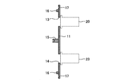
- FIG. 5 is a cross-sectional view of the counter pipe 11 for two pipes used when the heat exchange ventilation fan 50 according to the first embodiment is used as a two-pipe type heat exchange ventilation fan.
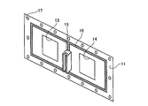
- FIG. 6 is a perspective view of the counter pipe 11 for two pipes in the first embodiment.
- the 2-pipe facing plate 11 is a plate-like member that is fixed to the flange portion 26 provided in the main body 1 and faces the back surface 6.
- the two-pipe facing plate 11 is fixed to the flange portion 26 with a screw 35 passed through the screw hole 17 to close the inside of the cylindrical surrounding wall 34.
- a packing 16 is provided between the two-pipe facing plate 11 and the flange portion 26 to prevent leakage of the supply air flow and the exhaust flow.
- a plate-side partitioning portion 15 is provided on a surface of the two-pipe facing plate 11 facing the back surface 6 side. As shown in FIG. 1, the plate-side partition 15 abuts on the housing-side partition 10 on the main body 1 side. The space surrounded by the back surface 6, the surrounding wall 34, and the two-plate facing plate 11 is in contact with the plate-side partition 15 and the housing-side partition 10, and the suction-side space that communicates with the outside air suction port 8. 37 and an exhaust outlet side space 36 communicating with the exhaust outlet 7.
- casing side partition part 10 become a shape where a mutual tip fits.
- the plate-side partition 15 and the housing-side partition 10 are in direct contact with each other, but another member is provided between the plate-side partition 15 and the housing-side partition 10. It may be a configuration in which is inserted.
- the two-pipe facing plate 11 is separately formed with a suction port side opening 14 communicating with the suction port side space 37 and an exhaust port side opening 13 communicating with the exhaust port side space 36.
- the position where the suction port side opening 14 is formed and the position where the exhaust port side opening 13 is formed are shown in FIG. 1 when the surrounding wall 34 of the main body 1 is brought into contact with the wall 30 as shown in FIG. The position coincides with the hole 30a formed in the.
- the exhaust pipe 20 and the air supply pipe 23 are inserted into the hole 30 a formed in the wall 30.
- the exhaust pipe 20 and the air supply pipe 23 are fixed to the wall 30 by a main body attachment plate 19 attached to the indoor side of the wall 30.
- An exhaust hood 21 is attached to the outdoor side of the exhaust pipe 20.
- An air supply hood 22 is attached to the outdoor side of the air supply pipe 23.
- the main body 1 to which the two-pipe counter plate 11 is attached is fixed to the wall 30 via the main body attachment plate 19, so that the exhaust air passage 32 connects the exhaust pipe 20 and the exhaust hood 21.
- the air supply air passage 33 is in communication with the outside through the air supply pipe 23 and the air supply hood 22.
- the air supply fan 3 is rotated, the air supply hood 22, the air supply pipe 23, the intake port side opening 14, the intake port side space 37, the outside air intake port 8, the supply air passage 33, the heat exchanger 5,
- the outdoor air can be supplied indoors through the outdoor air outlet 1b.
- the heat exchanging ventilator 50 can be used as a two-pipe type heat exchanging ventilator by attaching the counter plate 11 for two pipes to the flange portion 26 of the main body 1.
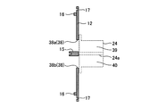
- FIG. 7 is a cross-sectional view of the one-pipe facing plate 12 used when the heat exchange ventilation fan 50 according to the first embodiment is used as a one-pipe type heat exchange ventilation fan.
- FIG. 8 is a perspective view of the counter pipe 12 for one pipe in the first embodiment.
- the counter pipe 12 for 1 pipe is a plate-like member that is fixed to the flange portion 26 provided in the main body 1 and faces the back surface 6.
- the one-pipe facing plate 12 is fixed to the flange portion 26 with a screw 35 passed through the screw hole 17, thereby closing the inside of the cylindrical surrounding wall 34.
- a packing 16 is provided between the one-pipe facing plate 12 and the flange portion 26 to prevent leakage of the supply air flow and the exhaust flow.
- a plate-side partition portion 15 is provided on the surface facing the back surface 6 side of the one-pipe facing plate 12. As shown in FIG. 2, the plate-side partition 15 abuts on the housing-side partition 10 on the main body 1 side.
- the space surrounded by the back surface 6, the surrounding wall 34, and the one-plate facing plate 12 is in contact with the plate-side partition 15 and the housing-side partition 10, and the suction-side space that communicates with the outside-air suction port 8. 37 and an exhaust outlet side space 36 communicating with the exhaust outlet 7.
- casing side partition part 10 become a shape where a mutual tip fits.
- the plate-side partition 15 and the housing-side partition 10 are in direct contact with each other, but another member is provided between the plate-side partition 15 and the housing-side partition 10. It may be a configuration in which is inserted.
- an opening 38 is formed so as to straddle the suction port side space 37 and the exhaust port side space 36.
- the plate-side partition 15 is configured to cross the opening 38.
- one side sandwiching the plate-side partition 15 is a suction port side opening 38 b communicating with the suction port side space 37
- the other side is an exhaust port side opening 38 a communicating with the exhaust port side space 36.
- the position where the opening 38 is formed is a position that coincides with the hole 31 a formed in the wall 31 when the surrounding wall 34 of the main body 1 is brought into contact with the wall 31.
- a supply / exhaust pipe 24 is inserted into the hole 31 a formed in the wall 31.
- the air supply / exhaust pipe 24 is fixed to the wall 31 by a main body attachment plate 19 attached to the indoor side of the wall 31.
- a supply / exhaust hood 25 is attached to the outdoor side of the supply / exhaust pipe 24.
- a partition plate 24 a that abuts the plate-side partition 15 of the one-pipe mounting plate 12 is provided inside the air supply / exhaust pipe 24, a partition plate 24 a that abuts the plate-side partition 15 of the one-pipe mounting plate 12 is provided. And an exhaust passage 39 through which the exhaust flow passes.
- the air supply / exhaust hood 25 can also suck or blow out the air supply flow and the exhaust flow separately.
- the main body 1 to which the one-pipe counter plate 12 is attached is fixed to the wall 31 via the main body attachment plate 19, so that the exhaust air passage 32 is the exhaust passage of the supply / exhaust pipe 24. 39 and the air supply / exhaust hood 25 communicate with the outside, and the air supply air passage 33 communicates with the outside through the air supply passage 40 of the air supply / exhaust pipe 24 and the air supply / exhaust hood 25.
- the exhaust fan 2 is rotated, the exhaust suction port 1a, the exhaust air passage 32, the heat exchanger 5, the exhaust outlet 7, the exhaust port side space 36, the exhaust port side opening 38a, the exhaust flow channel 39,
- the indoor air can be exhausted to the outside through the supply / exhaust hood 25.
- the air supply / exhaust hood 25 the air supply flow path 40, the suction port side opening 38b, the suction port side space 37, the outside air suction port 8, the air supply air passage 33, the heat exchanger 5,
- the outdoor air can be supplied indoors through the outdoor air outlet 1b.
- the heat exchange ventilation fan 50 can be used as a one-pipe type heat exchange ventilation fan by attaching the counter pipe 12 for one pipe to the flange portion 26 of the main body 1.
- the two-pipe heat exchanger ventilator can be used only by switching the counter plate attached to the flange portion 26 between the two-pipe counter plate 11 and the one-pipe counter plate 12. It can also be used as a type of heat exchange ventilation fan. Therefore, the main body 1 can be shared between the case of using as a 1-pipe type heat exchange ventilation fan and the case of using as a 2-pipe type heat exchange ventilation fan.
- the main body 1 exposed in the room is shared, the appearance is unified even when both the 1-pipe type heat exchange ventilation fan and the 2-pipe type heat exchange ventilation fan are installed in the same space. be able to.
- the configuration described in the above embodiment shows an example of the contents of the present invention, and can be combined with another known technique, and can be combined with other configurations without departing from the gist of the present invention. It is also possible to omit or change the part.
Landscapes
- Engineering & Computer Science (AREA)
- Chemical & Material Sciences (AREA)
- Combustion & Propulsion (AREA)
- Mechanical Engineering (AREA)
- General Engineering & Computer Science (AREA)
- Heat-Exchange Devices With Radiators And Conduit Assemblies (AREA)
- Devices For Blowing Cold Air, Devices For Blowing Warm Air, And Means For Preventing Water Condensation In Air Conditioning Units (AREA)
- Cooling Or The Like Of Electrical Apparatus (AREA)
- Duct Arrangements (AREA)
Abstract
Description
図1は、本発明の実施の形態1にかかる熱交換換気扇の概略構成を示す断面図であって、2パイプタイプの熱交換換気扇としての使用状態を示す図である。図2は、実施の形態1にかかる熱交換換気扇の概略構成を示す断面図であって、1パイプタイプの熱交換換気扇としての使用状態を示す図である。
Claims (5)
- 室外の空気を内部に取り込む外気吸込口と、前記外気吸込口から取り込まれた空気を室内に向けて吹き出す外気吹出口と、室内の空気を内部に取り込む排気吸込口と、前記排気吸込口から取り込まれた空気を室外に向けて吹き出す排気吹出口と、前記外気吸込口と前記外気吹出口とを結ぶ給気風路と、前記排気吸込口と前記排気吹出口とを結ぶ排気風路とが形成された筐体と、
前記給気風路に設けられて、前記給気風路の内部に前記外気吸込口から前記外気吹出口に向かう給気流を発生させる給気用ファンと、
前記排気風路に設けられて、前記排気風路の内部に前記排気吸込口から前記排気吹出口に向かう排気流を発生させる排気用ファンと、
前記筐体の内部に設けられて前記給気流と前記排気流との間で熱交換を行わせる熱交換器と、を備え、
前記外気吸込口と前記排気吹出口とは、前記筐体の背面に形成され、
前記背面に立設されて、前記外気吸込口と前記排気吹出口とをまとめて囲む囲み壁と
前記背面に設けられて、前記囲み壁に囲まれた領域を、前記外気吸込口が形成された領域と、前記排気吹出口が形成された領域とに仕切る筐体側仕切部と、
前記背面と対向して前記囲み壁の内側を覆う対向板と、をさらに備えることを特徴とする熱交換換気扇。 - 前記対向板には、前記筐体側仕切部と連結して、前記背面と前記囲み壁と前記対向板とに囲まれた空間を、前記外気吸込口に連通する吸込口側空間と、前記排気吹出口に連通する排気口側空間とに仕切る板側仕切部が設けられ、
前記対向板には、前記吸込口側空間に連通する吸込口側開口と前記排気口側空間に連通する排気口側開口とが別個に形成されていることを特徴とする請求項1に記載の熱交換換気扇。 - 前記対向板には、前記筐体側仕切部と連結して、前記背面と前記囲み壁と前記対向板とに囲まれた空間を、前記外気吸込口に連通する吸込口側空間と、前記排気吹出口に連通する排気口側空間とに仕切る板側仕切部が設けられ、
前記対向板には、前記吸込口側空間と前記排気口側空間とに跨る開口が形成されていることを特徴とする請求項1に記載の熱交換換気扇。 - 前記筐体側仕切部と前記板側仕切部とが嵌まり合って、前記背面と前記囲み壁と前記対向板とに囲まれた空間が、前記吸込口側空間と前記排気口側空間とに仕切られることを特徴とする請求項2または3に記載の熱交換換気扇。
- 前記外気吸込口を開閉させる吸込口シャッターと、
前記排気吹出口を開閉させる吹出口シャッターと、をさらに備えることを特徴とする請求項1に記載の熱交換換気扇。
Priority Applications (3)
| Application Number | Priority Date | Filing Date | Title |
|---|---|---|---|
| JP2018506717A JP6482727B2 (ja) | 2016-03-24 | 2016-03-24 | 熱交換換気扇 |
| PCT/JP2016/059498 WO2017163387A1 (ja) | 2016-03-24 | 2016-03-24 | 熱交換換気扇 |
| EP16895423.8A EP3434990A4 (en) | 2016-03-24 | 2016-03-24 | HEAT EXCHANGE VENTILATION FAN |
Applications Claiming Priority (1)
| Application Number | Priority Date | Filing Date | Title |
|---|---|---|---|
| PCT/JP2016/059498 WO2017163387A1 (ja) | 2016-03-24 | 2016-03-24 | 熱交換換気扇 |
Publications (1)
| Publication Number | Publication Date |
|---|---|
| WO2017163387A1 true WO2017163387A1 (ja) | 2017-09-28 |
Family
ID=59900100
Family Applications (1)
| Application Number | Title | Priority Date | Filing Date |
|---|---|---|---|
| PCT/JP2016/059498 Ceased WO2017163387A1 (ja) | 2016-03-24 | 2016-03-24 | 熱交換換気扇 |
Country Status (3)
| Country | Link |
|---|---|
| EP (1) | EP3434990A4 (ja) |
| JP (1) | JP6482727B2 (ja) |
| WO (1) | WO2017163387A1 (ja) |
Cited By (1)
| Publication number | Priority date | Publication date | Assignee | Title |
|---|---|---|---|---|
| WO2025164074A1 (ja) * | 2024-01-31 | 2025-08-07 | シャープ株式会社 | 全熱交換換気装置及び全熱交換換気システム |
Citations (6)
| Publication number | Priority date | Publication date | Assignee | Title |
|---|---|---|---|---|
| JPH02298746A (ja) * | 1989-05-12 | 1990-12-11 | Mitsubishi Electric Corp | 天井設置型熱交換換気装置 |
| JPH044642U (ja) * | 1990-04-25 | 1992-01-16 | ||
| JPH0413034A (ja) * | 1990-04-27 | 1992-01-17 | Mitsubishi Electric Corp | 換気装置 |
| JPH0420733A (ja) * | 1990-05-15 | 1992-01-24 | Mitsubishi Electric Corp | 換気扇 |
| JPH06313601A (ja) * | 1993-04-28 | 1994-11-08 | Matsushita Seiko Co Ltd | 熱交換形換気扇 |
| JP2005055032A (ja) * | 2003-08-01 | 2005-03-03 | Mitsubishi Electric Corp | 給排気換気扇 |
Family Cites Families (2)
| Publication number | Priority date | Publication date | Assignee | Title |
|---|---|---|---|---|
| JPS5646734U (ja) * | 1979-09-14 | 1981-04-25 | ||
| JP2012211728A (ja) * | 2011-03-31 | 2012-11-01 | Panasonic Corp | 同時給排形換気扇取付装置 |
-
2016
- 2016-03-24 JP JP2018506717A patent/JP6482727B2/ja active Active
- 2016-03-24 EP EP16895423.8A patent/EP3434990A4/en not_active Withdrawn
- 2016-03-24 WO PCT/JP2016/059498 patent/WO2017163387A1/ja not_active Ceased
Patent Citations (6)
| Publication number | Priority date | Publication date | Assignee | Title |
|---|---|---|---|---|
| JPH02298746A (ja) * | 1989-05-12 | 1990-12-11 | Mitsubishi Electric Corp | 天井設置型熱交換換気装置 |
| JPH044642U (ja) * | 1990-04-25 | 1992-01-16 | ||
| JPH0413034A (ja) * | 1990-04-27 | 1992-01-17 | Mitsubishi Electric Corp | 換気装置 |
| JPH0420733A (ja) * | 1990-05-15 | 1992-01-24 | Mitsubishi Electric Corp | 換気扇 |
| JPH06313601A (ja) * | 1993-04-28 | 1994-11-08 | Matsushita Seiko Co Ltd | 熱交換形換気扇 |
| JP2005055032A (ja) * | 2003-08-01 | 2005-03-03 | Mitsubishi Electric Corp | 給排気換気扇 |
Non-Patent Citations (1)
| Title |
|---|
| See also references of EP3434990A4 * |
Cited By (1)
| Publication number | Priority date | Publication date | Assignee | Title |
|---|---|---|---|---|
| WO2025164074A1 (ja) * | 2024-01-31 | 2025-08-07 | シャープ株式会社 | 全熱交換換気装置及び全熱交換換気システム |
Also Published As
| Publication number | Publication date |
|---|---|
| EP3434990A4 (en) | 2019-04-17 |
| JP6482727B2 (ja) | 2019-03-13 |
| JPWO2017163387A1 (ja) | 2018-06-28 |
| EP3434990A1 (en) | 2019-01-30 |
Similar Documents
| Publication | Publication Date | Title |
|---|---|---|
| KR101578528B1 (ko) | 바이패스 유로를 별도로 구비한 열회수 환기장치 | |
| CN102012074A (zh) | 通风设备 | |
| WO2011089728A1 (ja) | 換気端末装置および換気システム | |
| WO2004051152A1 (ja) | 給排気型レンジフード | |
| JP6482727B2 (ja) | 熱交換換気扇 | |
| JPH1078245A (ja) | 空気調和装置 | |
| JP6577273B2 (ja) | ミキシングチャンバー | |
| JP6097931B2 (ja) | 熱交換形換気装置 | |
| JP2009180471A (ja) | 換気装置 | |
| JP2010159909A (ja) | 空気調和装置 | |
| KR20100109666A (ko) | 일체형 급배기 후드 | |
| KR101251221B1 (ko) | 창호 환기시스템 | |
| JP5247610B2 (ja) | 熱交換換気装置 | |
| JP4391099B2 (ja) | 熱交換換気装置 | |
| KR20170035824A (ko) | 환기시스템의 바이패스장치 | |
| AU2016423907B2 (en) | Ventilation blower | |
| EP3633284A1 (en) | Duct connection port and ventilation device | |
| JP2007024358A (ja) | 空調システムおよびこの空調システムを備えた建物 | |
| JP7249485B2 (ja) | 熱交換形換気装置 | |
| WO2017056152A1 (ja) | 室内機 | |
| JP4300666B2 (ja) | 床置形空気調和機 | |
| JP4910323B2 (ja) | 熱交換型換気装置、この熱交換型換気装置を備える空調システムおよびこの空調システムを備えた建物 | |
| JP7253682B2 (ja) | 加湿ユニット | |
| JP2020197317A (ja) | 熱交換換気装置 | |
| KR20170095785A (ko) | 환기시스템의 바이패스장치 |
Legal Events
| Date | Code | Title | Description |
|---|---|---|---|
| ENP | Entry into the national phase |
Ref document number: 2018506717 Country of ref document: JP Kind code of ref document: A |
|
| NENP | Non-entry into the national phase |
Ref country code: DE |
|
| WWE | Wipo information: entry into national phase |
Ref document number: 2016895423 Country of ref document: EP |
|
| ENP | Entry into the national phase |
Ref document number: 2016895423 Country of ref document: EP Effective date: 20181024 |
|
| 121 | Ep: the epo has been informed by wipo that ep was designated in this application |
Ref document number: 16895423 Country of ref document: EP Kind code of ref document: A1 |