WO2017163405A1 - 3次元積層造形装置、3次元積層造形装置の制御方法および3次元積層造形装置の制御プログラム - Google Patents
3次元積層造形装置、3次元積層造形装置の制御方法および3次元積層造形装置の制御プログラム Download PDFInfo
- Publication number
- WO2017163405A1 WO2017163405A1 PCT/JP2016/059645 JP2016059645W WO2017163405A1 WO 2017163405 A1 WO2017163405 A1 WO 2017163405A1 JP 2016059645 W JP2016059645 W JP 2016059645W WO 2017163405 A1 WO2017163405 A1 WO 2017163405A1
- Authority
- WO
- WIPO (PCT)
- Prior art keywords
- modeling
- dimensional
- additive manufacturing
- thermal expansion
- base material
- Prior art date
- Legal status (The legal status is an assumption and is not a legal conclusion. Google has not performed a legal analysis and makes no representation as to the accuracy of the status listed.)
- Ceased
Links
Images





Classifications
-
- B—PERFORMING OPERATIONS; TRANSPORTING
- B29—WORKING OF PLASTICS; WORKING OF SUBSTANCES IN A PLASTIC STATE IN GENERAL
- B29C—SHAPING OR JOINING OF PLASTICS; SHAPING OF MATERIAL IN A PLASTIC STATE, NOT OTHERWISE PROVIDED FOR; AFTER-TREATMENT OF THE SHAPED PRODUCTS, e.g. REPAIRING
- B29C64/00—Additive manufacturing, i.e. manufacturing of three-dimensional [3D] objects by additive deposition, additive agglomeration or additive layering, e.g. by 3D printing, stereolithography or selective laser sintering
- B29C64/10—Processes of additive manufacturing
- B29C64/141—Processes of additive manufacturing using only solid materials
- B29C64/153—Processes of additive manufacturing using only solid materials using layers of powder being selectively joined, e.g. by selective laser sintering or melting
-
- B—PERFORMING OPERATIONS; TRANSPORTING
- B22—CASTING; POWDER METALLURGY
- B22F—WORKING METALLIC POWDER; MANUFACTURE OF ARTICLES FROM METALLIC POWDER; MAKING METALLIC POWDER; APPARATUS OR DEVICES SPECIALLY ADAPTED FOR METALLIC POWDER
- B22F12/00—Apparatus or devices specially adapted for additive manufacturing; Auxiliary means for additive manufacturing; Combinations of additive manufacturing apparatus or devices with other processing apparatus or devices
- B22F12/60—Planarisation devices; Compression devices
- B22F12/67—Blades
-
- B—PERFORMING OPERATIONS; TRANSPORTING
- B23—MACHINE TOOLS; METAL-WORKING NOT OTHERWISE PROVIDED FOR
- B23K—SOLDERING OR UNSOLDERING; WELDING; CLADDING OR PLATING BY SOLDERING OR WELDING; CUTTING BY APPLYING HEAT LOCALLY, e.g. FLAME CUTTING; WORKING BY LASER BEAM
- B23K15/00—Electron-beam welding or cutting
- B23K15/0046—Welding
- B23K15/0086—Welding welding for purposes other than joining, e.g. build-up welding
-
- B—PERFORMING OPERATIONS; TRANSPORTING
- B23—MACHINE TOOLS; METAL-WORKING NOT OTHERWISE PROVIDED FOR
- B23K—SOLDERING OR UNSOLDERING; WELDING; CLADDING OR PLATING BY SOLDERING OR WELDING; CUTTING BY APPLYING HEAT LOCALLY, e.g. FLAME CUTTING; WORKING BY LASER BEAM
- B23K15/00—Electron-beam welding or cutting
- B23K15/0046—Welding
- B23K15/0093—Welding characterised by the properties of the materials to be welded
-
- B—PERFORMING OPERATIONS; TRANSPORTING
- B23—MACHINE TOOLS; METAL-WORKING NOT OTHERWISE PROVIDED FOR
- B23K—SOLDERING OR UNSOLDERING; WELDING; CLADDING OR PLATING BY SOLDERING OR WELDING; CUTTING BY APPLYING HEAT LOCALLY, e.g. FLAME CUTTING; WORKING BY LASER BEAM
- B23K15/00—Electron-beam welding or cutting
- B23K15/06—Electron-beam welding or cutting within a vacuum chamber
-
- B—PERFORMING OPERATIONS; TRANSPORTING
- B29—WORKING OF PLASTICS; WORKING OF SUBSTANCES IN A PLASTIC STATE IN GENERAL
- B29C—SHAPING OR JOINING OF PLASTICS; SHAPING OF MATERIAL IN A PLASTIC STATE, NOT OTHERWISE PROVIDED FOR; AFTER-TREATMENT OF THE SHAPED PRODUCTS, e.g. REPAIRING
- B29C64/00—Additive manufacturing, i.e. manufacturing of three-dimensional [3D] objects by additive deposition, additive agglomeration or additive layering, e.g. by 3D printing, stereolithography or selective laser sintering
- B29C64/20—Apparatus for additive manufacturing; Details thereof or accessories therefor
- B29C64/205—Means for applying layers
-
- B—PERFORMING OPERATIONS; TRANSPORTING
- B29—WORKING OF PLASTICS; WORKING OF SUBSTANCES IN A PLASTIC STATE IN GENERAL
- B29C—SHAPING OR JOINING OF PLASTICS; SHAPING OF MATERIAL IN A PLASTIC STATE, NOT OTHERWISE PROVIDED FOR; AFTER-TREATMENT OF THE SHAPED PRODUCTS, e.g. REPAIRING
- B29C64/00—Additive manufacturing, i.e. manufacturing of three-dimensional [3D] objects by additive deposition, additive agglomeration or additive layering, e.g. by 3D printing, stereolithography or selective laser sintering
- B29C64/20—Apparatus for additive manufacturing; Details thereof or accessories therefor
- B29C64/264—Arrangements for irradiation
- B29C64/268—Arrangements for irradiation using laser beams; using electron beams [EB]
-
- B—PERFORMING OPERATIONS; TRANSPORTING
- B33—ADDITIVE MANUFACTURING TECHNOLOGY
- B33Y—ADDITIVE MANUFACTURING, i.e. MANUFACTURING OF THREE-DIMENSIONAL [3D] OBJECTS BY ADDITIVE DEPOSITION, ADDITIVE AGGLOMERATION OR ADDITIVE LAYERING, e.g. BY 3D PRINTING, STEREOLITHOGRAPHY OR SELECTIVE LASER SINTERING
- B33Y30/00—Apparatus for additive manufacturing; Details thereof or accessories therefor
-
- B—PERFORMING OPERATIONS; TRANSPORTING
- B22—CASTING; POWDER METALLURGY
- B22F—WORKING METALLIC POWDER; MANUFACTURE OF ARTICLES FROM METALLIC POWDER; MAKING METALLIC POWDER; APPARATUS OR DEVICES SPECIALLY ADAPTED FOR METALLIC POWDER
- B22F10/00—Additive manufacturing of workpieces or articles from metallic powder
- B22F10/20—Direct sintering or melting
- B22F10/28—Powder bed fusion, e.g. selective laser melting [SLM] or electron beam melting [EBM]
-
- B—PERFORMING OPERATIONS; TRANSPORTING
- B29—WORKING OF PLASTICS; WORKING OF SUBSTANCES IN A PLASTIC STATE IN GENERAL
- B29C—SHAPING OR JOINING OF PLASTICS; SHAPING OF MATERIAL IN A PLASTIC STATE, NOT OTHERWISE PROVIDED FOR; AFTER-TREATMENT OF THE SHAPED PRODUCTS, e.g. REPAIRING
- B29C64/00—Additive manufacturing, i.e. manufacturing of three-dimensional [3D] objects by additive deposition, additive agglomeration or additive layering, e.g. by 3D printing, stereolithography or selective laser sintering
- B29C64/20—Apparatus for additive manufacturing; Details thereof or accessories therefor
- B29C64/245—Platforms or substrates
-
- B—PERFORMING OPERATIONS; TRANSPORTING
- B29—WORKING OF PLASTICS; WORKING OF SUBSTANCES IN A PLASTIC STATE IN GENERAL
- B29C—SHAPING OR JOINING OF PLASTICS; SHAPING OF MATERIAL IN A PLASTIC STATE, NOT OTHERWISE PROVIDED FOR; AFTER-TREATMENT OF THE SHAPED PRODUCTS, e.g. REPAIRING
- B29C64/00—Additive manufacturing, i.e. manufacturing of three-dimensional [3D] objects by additive deposition, additive agglomeration or additive layering, e.g. by 3D printing, stereolithography or selective laser sintering
- B29C64/30—Auxiliary operations or equipment
- B29C64/386—Data acquisition or data processing for additive manufacturing
- B29C64/393—Data acquisition or data processing for additive manufacturing for controlling or regulating additive manufacturing processes
-
- B—PERFORMING OPERATIONS; TRANSPORTING
- B33—ADDITIVE MANUFACTURING TECHNOLOGY
- B33Y—ADDITIVE MANUFACTURING, i.e. MANUFACTURING OF THREE-DIMENSIONAL [3D] OBJECTS BY ADDITIVE DEPOSITION, ADDITIVE AGGLOMERATION OR ADDITIVE LAYERING, e.g. BY 3D PRINTING, STEREOLITHOGRAPHY OR SELECTIVE LASER SINTERING
- B33Y10/00—Processes of additive manufacturing
-
- B—PERFORMING OPERATIONS; TRANSPORTING
- B33—ADDITIVE MANUFACTURING TECHNOLOGY
- B33Y—ADDITIVE MANUFACTURING, i.e. MANUFACTURING OF THREE-DIMENSIONAL [3D] OBJECTS BY ADDITIVE DEPOSITION, ADDITIVE AGGLOMERATION OR ADDITIVE LAYERING, e.g. BY 3D PRINTING, STEREOLITHOGRAPHY OR SELECTIVE LASER SINTERING
- B33Y50/00—Data acquisition or data processing for additive manufacturing
- B33Y50/02—Data acquisition or data processing for additive manufacturing for controlling or regulating additive manufacturing processes
-
- Y—GENERAL TAGGING OF NEW TECHNOLOGICAL DEVELOPMENTS; GENERAL TAGGING OF CROSS-SECTIONAL TECHNOLOGIES SPANNING OVER SEVERAL SECTIONS OF THE IPC; TECHNICAL SUBJECTS COVERED BY FORMER USPC CROSS-REFERENCE ART COLLECTIONS [XRACs] AND DIGESTS
- Y02—TECHNOLOGIES OR APPLICATIONS FOR MITIGATION OR ADAPTATION AGAINST CLIMATE CHANGE
- Y02P—CLIMATE CHANGE MITIGATION TECHNOLOGIES IN THE PRODUCTION OR PROCESSING OF GOODS
- Y02P10/00—Technologies related to metal processing
- Y02P10/25—Process efficiency
Definitions
- the present invention relates to a control method for a three-dimensional additive manufacturing apparatus, a control method for the three-dimensional additive manufacturing apparatus, and a control program for the three-dimensional additive manufacturing apparatus.
- Patent Document 1 discloses a technique for setting the Young's modulus of the modeling plate to 150 to 800 GPa.
- An object of the present invention is to provide a technique for solving the above-described problems.
- a three-dimensional additive manufacturing apparatus Material spreading means for spreading the material of the three-dimensional layered object, An electron gun that generates an electron beam; A modeling base material on which the three-dimensional layered object is modeled; With The thermal expansion coefficient between the modeling base material and the three-dimensional layered object is the same or the difference is within a predetermined value.
- a method for controlling a three-dimensional additive manufacturing apparatus includes: A material spraying step of spraying the material of the three-dimensional layered object by a material spraying means; A modeling step of generating an electron beam by an electron gun and modeling the three-dimensional layered object on a modeling base material; Including The thermal expansion coefficient between the modeling base material and the three-dimensional layered object is the same or the difference is within a predetermined value.
- a control program for a three-dimensional additive manufacturing apparatus is: A material spraying step of spraying the material of the three-dimensional layered object by a material spraying means; A modeling step of generating an electron beam by an electron gun and modeling the three-dimensional layered object on a modeling base material; To the computer, The thermal expansion coefficient between the modeling base material and the three-dimensional layered object is the same or the difference is within a predetermined value.
- FIG. 1 shows the structure of the three-dimensional layered modeling apparatus which concerns on 1st Embodiment of this invention. It is a figure explaining the three-dimensional layered product modeled by the three-dimensional layered modeling apparatus according to the first embodiment of the present invention. It is a flowchart explaining the process sequence of the three-dimensional layered modeling apparatus which concerns on 1st Embodiment of this invention. It is a figure explaining the three-dimensional additive manufacturing object modeled by the three-dimensional additive manufacturing apparatus which concerns on the premise technique of the three-dimensional additive manufacturing apparatus which concerns on 1st Embodiment of this invention. It is a figure explaining the three-dimensional layered object modeled by the three-dimensional layered modeling apparatus concerning 2nd Embodiment of this invention.
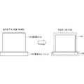
- FIG. 4 is a diagram illustrating a three-dimensional layered object modeled by the three-dimensional layered modeling apparatus according to the prerequisite technology of the three-dimensional layered modeling apparatus according to the present embodiment.
- the three-dimensional layered object 430 is in a high temperature state and in an expanded state due to the heat given by the electron beam when the modeling is completed.
- the three-dimensional layered object 430 contracts with the cooling.
- thermal stress is generated, and the defect 410 enters the three-dimensional layered object 430 or the shape of the three-dimensional layered object 430 is distorted, resulting in a decrease in modeling accuracy.
- FIG. 1 is a diagram illustrating a configuration of a three-dimensional additive manufacturing apparatus according to the present embodiment.
- the three-dimensional additive manufacturing apparatus 100 includes a vacuum container 101, an electron gun 102, a modeling frame base 103, a Z-axis drive mechanism 104, a linear funnel 105, and a modeling plate 106.
- the three-dimensional additive manufacturing apparatus 100 is a powder bed type apparatus.
- the 3D additive manufacturing apparatus 100 arranges the upper surface of the modeling plate 106 at substantially the same height as the upper surface of the modeling frame base 103. Then, the three-dimensional additive manufacturing apparatus 100 spreads the material on the modeling plate 106 (on the base plate) by the linear funnel 105 that is a material dispersion unit filled with the material of the three-dimensional additive manufacturing object 130. The three-dimensional additive manufacturing apparatus 100 irradiates the spread material with the electron beam 121 generated by the electron gun 102 to melt and solidify the material, thereby completing the lamination of one layer of material.
- the material of the modeling plate 106 is typically stainless steel, but is not limited thereto.
- the three-dimensional layered modeling apparatus 100 lowers the modeling table 140 by a height corresponding to the height of one layer by the Z-axis drive mechanism 104, so that the material of the next layer is obtained. Cover with line funnel 105. When the material is spread, the electron beam 121 is irradiated to melt and solidify the material, thereby completing the next one layer of material.
- the three-dimensional additive manufacturing apparatus 100 repeats this operation to form a desired three-dimensional additive manufacturing object in the vacuum vessel 101.
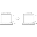
- FIG. 2 is a diagram illustrating a three-dimensional layered object that is formed by the three-dimensional layered object manufacturing apparatus according to the present embodiment.
- the three-dimensional layered object 130 is modeled on a modeling plate 106 that is a modeling base material.
- the three-dimensional layered object 130 at the time of completion of modeling is heated by heat (energy) provided by the electron beam 121 and is thermally expanded.
- the modeling plate 106 and the three-dimensional layered object 130 have the same or similar values of thermal expansion (the difference between the two is within a predetermined value), so there is no difference in the shrinkage rate during cooling, and they are pulled together. Cool and solidify without matching.
- modeling plate 106 was demonstrated to the example here as a modeling base material, a modeling base material is not limited to this, For example, another 3D layered modeling thing etc. are good also as a modeling base material. That is, for example, even when a three-dimensional layered object is formed on a certain product or part, the technique of the present embodiment may be applied.
- FIG. 3 is a flowchart for explaining the processing procedure of the three-dimensional additive manufacturing apparatus 100 according to the present embodiment.
- the three-dimensional additive manufacturing apparatus 100 acquires modeling data of the three-dimensional additive manufacturing object 130.
- a modeling plate 106 is selected that has the same coefficient of thermal expansion as that of the three-dimensional layered object 130 or a difference within a predetermined value.
- the three-dimensional additive manufacturing apparatus 100 scatters the material of the three-dimensional additive manufacturing object 130 on the modeling plate 106 and irradiates the scattered material with the electron beam 121.
- step S307 the three-dimensional additive manufacturing apparatus 100 determines whether or not the three-dimensional additive object 130 has been formed.
- step S307 When it is determined that the modeling has not been completed (NO in step S307), the three-dimensional layered modeling apparatus 100 repeats the steps after step S305. When it is determined that the modeling is completed (YES in step S307), the three-dimensional layered modeling apparatus 100 ends the process.
- the present embodiment it is possible to effectively suppress a decrease in modeling accuracy based on the difference in thermal expansion coefficient between the three-dimensional layered object and the modeling plate, and to reduce damage to the three-dimensional layered object. it can. Moreover, it is possible to effectively suppress the occurrence of defects and the occurrence of thermal strain due to the difference in thermal expansion coefficient.
- a three-dimensional layered object modeled by the three-dimensional layered object modeling apparatus according to the second embodiment of the present invention will be described with reference to FIG.
- a groove is carved on the surface of the modeling plate 506 that is a modeling base material, and the surface of the modeling plate 506 is provided with unevenness.
- the unevenness on the surface of the modeling plate 506 is provided on the surface on which the three-dimensional layered object 130 is stacked and modeled, that is, on the upper surface side of the modeling plate 506.
- corrugation provided in the surface of a modeling base material is not limited to a groove shape, For example, a wave shape, a zigzag shape, etc. may be sufficient.
- the stress on the three-dimensional layered object can be relieved with the expansion and contraction of the modeling plate, so that the occurrence of defects, thermal distortion, etc. Can be suppressed. Moreover, damage to the three-dimensional layered object can be reduced. A decrease in modeling accuracy based on the difference in thermal expansion coefficient between the three-dimensional layered object and the modeling plate can be suppressed. Moreover, generation
- the modeling plate 106 that is a modeling base material and the three-dimensional additive manufacturing object 130 are different materials.
- An intermediate layer is provided between the modeling plate 106, which is a modeling base material, and the three-dimensional layered object 130. That is, in the present embodiment, another modeling plate 601 is provided as an intermediate layer on the upper surface of the modeling plate 106.
- the modeling plate 601 as an intermediate layer is provided in order to prevent a defect or the like from occurring in the three-dimensional layered object 130 due to the difference in expansion and contraction between the modeling plate 106 and the three-dimensional layered object 130. Even if a defect occurs, a defect due to the influence of thermal stress is prevented from reaching the three-dimensional layered object 130 by entering the modeling plate 601 as an intermediate layer.
- the shape of the modeling plate 601 as the intermediate layer may be a flat plate shape or a lattice shape. For example, if the modeling plate 601 is formed in a lattice shape, when thermal stress is generated, the influence of the thermal stress on the three-dimensional layered object 130 can be reduced by damaging only the portion where the thermal stress is generated. it can.
- the intermediate layer since the intermediate layer is provided, the influence of thermal stress on the three-dimensional layered object can be mitigated. Moreover, the fall of the modeling precision based on the difference in the thermal expansion coefficient of a three-dimensional laminate modeling thing and a modeling plate can be suppressed. Moreover, generation
- a three-dimensional layered object modeled by the three-dimensional layered object modeling apparatus according to the fourth embodiment of the present invention will be described with reference to FIG.
- a plurality of intermediate layers are provided between the modeling base material 106 and the three-dimensional additive manufacturing object 130. That is, when the thermal expansion coefficients of the modeling plate 106 and the three-dimensional layered object 130 are greatly different, a plurality of intermediate layers are provided, and the influence of thermal stress transmitted from the modeling plate 106 to the three-dimensional layered object 130 is gradually increased. To be relaxed.
- the thermal expansion coefficient of the three-dimensional layered object 130 is A
- the thermal expansion coefficient of the modeling plate 106 is B
- the thermal expansion coefficient of the modeling plate 701 in the intermediate layer immediately above the modeling plate 106 is B ⁇ ⁇ , which is close to the modeling plate 106
- the thermal expansion coefficient of the modeling plate 702 on the modeling plate 701 is three-dimensionally stacked.
- a ⁇ ⁇ , which is close to the modeled object 130, is assumed. Note that the coefficient of thermal expansion ⁇ is small and does not cause thermal stress.
- the thermal expansion coefficients of the modeling plate and the three-dimensional layered object are greatly different, a plurality of intermediate layers are provided, so that the influence of thermal stress on the three-dimensional layered object is gradually increased. It can alleviate and finally suppress the occurrence of damage to the three-dimensional layered object. Moreover, the fall of the modeling precision based on the difference in the thermal expansion coefficient of a three-dimensional laminate modeling thing and a modeling plate can be suppressed. Moreover, generation
- the present invention may be applied to a system composed of a plurality of devices, or may be applied to a single device. Furthermore, the present invention can also be applied to a case where an information processing program that implements the functions of the embodiments is supplied directly or remotely to a system or apparatus. Therefore, in order to realize the functions of the present invention on a computer, a program installed on the computer, a medium storing the program, and a WWW (World Wide Web) server that downloads the program are also included in the scope of the present invention. . In particular, at least a non-transitory computer readable medium storing a program for causing a computer to execute the processing steps included in the above-described embodiments is included in the scope of the present invention.
Landscapes
- Engineering & Computer Science (AREA)
- Chemical & Material Sciences (AREA)
- Materials Engineering (AREA)
- Mechanical Engineering (AREA)
- Physics & Mathematics (AREA)
- Optics & Photonics (AREA)
- Manufacturing & Machinery (AREA)
- Plasma & Fusion (AREA)
- Health & Medical Sciences (AREA)
- Toxicology (AREA)
- Powder Metallurgy (AREA)
Abstract
3次元積層造形物と造形プレートとの熱膨張率の相違に基づく造形精度の低下を効果的に抑制すること。3次元積層造形装置であって、3次元積層造形物の材料を散布する線状漏斗を備える。また、3次元積層造形装置であって、電子ビームを発生させる電子銃を備える。さらに、3次元積層造形装置であって、前記3次元積層造形物が造形される造形母材を備える。そして、前記造形母材熱膨張率と前記3次元積層造形物との熱膨張率は、等しいか、または差が所定の値以内である。
Description
本発明は、3次元積層造形装置、3次元積層造形装置の制御方法および3次元積層造形装置の制御プログラムに関する。
上記技術分野において、特許文献1には、造形プレートのヤング率を150~800GPaとする技術が開示されている。
しかしながら、上記文献に記載の技術では、3次元積層造形物と造形プレートとの熱膨張率の相違に基づく造形精度の低下を効果的に抑制することができなかった。
本発明の目的は、上述の課題を解決する技術を提供することにある。
上記目的を達成するため、本発明に係る3次元積層造形装置は、
3次元積層造形物の材料を散布する材料散布手段と、
電子ビームを発生させる電子銃と、
前記3次元積層造形物が造形される造形母材と、
を備え、
前記造形母材熱膨張率と前記3次元積層造形物との熱膨張率は、等しいか、または差が所定の値以内である。
3次元積層造形物の材料を散布する材料散布手段と、
電子ビームを発生させる電子銃と、
前記3次元積層造形物が造形される造形母材と、
を備え、
前記造形母材熱膨張率と前記3次元積層造形物との熱膨張率は、等しいか、または差が所定の値以内である。
上記目的を達成するため、本発明に係る3次元積層造形装置の制御方法は、
3次元積層造形物の材料を材料散布手段により散布する材料散布ステップと、
電子銃により電子ビームを発生させて、造形母材に前記3次元積層造形物を造形する造形ステップと、
を含み、
前記造形母材熱膨張率と前記3次元積層造形物との熱膨張率は、等しいか、または差が所定の値以内である。
3次元積層造形物の材料を材料散布手段により散布する材料散布ステップと、
電子銃により電子ビームを発生させて、造形母材に前記3次元積層造形物を造形する造形ステップと、
を含み、
前記造形母材熱膨張率と前記3次元積層造形物との熱膨張率は、等しいか、または差が所定の値以内である。
上記目的を達成するため、本発明に係る3次元積層造形装置の制御プログラムは、
3次元積層造形物の材料を材料散布手段により散布する材料散布ステップと、
電子銃により電子ビームを発生させて、造形母材に前記3次元積層造形物を造形する造形ステップと、
をコンピュータに実行させ、
前記造形母材熱膨張率と前記3次元積層造形物との熱膨張率は、等しいか、または差が所定の値以内である。
3次元積層造形物の材料を材料散布手段により散布する材料散布ステップと、
電子銃により電子ビームを発生させて、造形母材に前記3次元積層造形物を造形する造形ステップと、
をコンピュータに実行させ、
前記造形母材熱膨張率と前記3次元積層造形物との熱膨張率は、等しいか、または差が所定の値以内である。
本発明によれば、3次元積層造形物と造形プレートとの熱膨張率の相違に基づく造形精度の低下を効果的に抑制することができる。
以下に、本発明を実施するための形態について、図面を参照して、例示的に詳しく説明記載する。ただし、以下の実施の形態に記載されている、構成、数値、処理の流れ、機能要素などは一例に過ぎず、その変形や変更は自由であって、本発明の技術範囲を以下の記載に限定する趣旨のものではない。
[第1実施形態]
本発明の第1実施形態としての3次元積層造形装置100について、図1乃至図4を用いて説明する。
本発明の第1実施形態としての3次元積層造形装置100について、図1乃至図4を用いて説明する。
<前提技術>
図4は、本実施形態に係る3次元積層造形装置の前提技術に係る3次元積層造形装置により造形される3次元積層造形物について説明する図である。
図4は、本実施形態に係る3次元積層造形装置の前提技術に係る3次元積層造形装置により造形される3次元積層造形物について説明する図である。
3次元積層造形物430は、造形完了時には、電子ビームにより与えられた熱により、高温状態にあり、膨張した状態にある。そして、造形が完了して、3次元積層造形物430を冷却すると、冷却に伴って3次元積層造形物430が収縮する。しかしながら、この収縮時に、熱応力が発生して、3次元積層造形物430に欠陥410が入ったり、3次元積層造形物430の形状が歪んだりして、造形精度が低下する。
この収縮する過程において、3次元積層造形物430の熱膨張率Aが、造形プレート(ベースプレート)406の熱膨張率Bよりも大きい場合、3次元積層造形物430に熱応力が発生し、3次元積層造形物430に欠陥410などが入り、造形精度が低下する。つまり、造形プレート406の熱膨張率が3次元積層造形物430の熱膨張率よりも小さいため、3次元積層造形物430が引っ張られるような力が働き、3次元積層造形物430に欠陥410が入る。
<本実施形態の技術>
図1は、本実施形態に係る3次元積層造形装置の構成を示す図である。3次元積層造形装置100は、真空容器101と、電子銃102と、造形枠台103と、Z軸駆動機構104と、線状漏斗105と、造形プレート106とを備える。なお、以下の説明においては、3次元積層造形装置100は、パウダーベッド方式の装置である。
図1は、本実施形態に係る3次元積層造形装置の構成を示す図である。3次元積層造形装置100は、真空容器101と、電子銃102と、造形枠台103と、Z軸駆動機構104と、線状漏斗105と、造形プレート106とを備える。なお、以下の説明においては、3次元積層造形装置100は、パウダーベッド方式の装置である。
3次元積層造形装置100は、造形プレート106上面を造形枠台103の上面とほぼ同じ高さに配置する。そして、3次元積層造形装置100は、3次元積層造形物130の材料が充填された材料散布部である線状漏斗105により造形プレート106上(ベースプレート上)に材料を敷き詰める。3次元積層造形装置100は、敷き詰めた材料に電子銃102で発生させた電子ビーム121を照射して、材料を溶融し、凝固させ、1層分の材料の積層を完成させる。なお、造形プレート106の材質は、ステンレス鋼が代表的であるが、これには限定されない。
そして、1層分の積層が完了したら、3次元積層造形装置100は、Z軸駆動機構104により1層分の高さに相当する高さだけ造形台140を下げて、次の層の材料を線状漏斗105により敷き詰める。材料を敷き詰めたら、電子ビーム121を照射して、材料を溶融し、凝固させ、次の1層分の材料の積層を完成させる。3次元積層造形装置100は、この動作を繰り返して、真空容器101内で所望の3次元積層造形物を造形する。
図2は、本実施形態に係る3次元積層造形装置により造形される3次元積層造形物について説明する図である。3次元積層造形物130は、造形母材である造形プレート106上に造形される。造形完了時の3次元積層造形物130は、電子ビーム121により与えられた熱(エネルギー)により高温となっており、熱膨張している。 この場合、造形プレート106の熱膨張率(Cb)と、3次元積層造形物130の熱膨張率(C)とを近いもの、すなわち、Cb=A±α、C=A(αは、熱応力を生じない程度に小さいものとする)としておく。そうすると、造形プレート106と3次元積層造形物130とは、熱膨張率が等しいか、または近い値(両者の差が、所定の値以内)なので、冷却時の収縮率に差がなく、互いに引っ張り合うことなく冷却し、固化する。
したがって、造形プレート106と3次元積層造形物130とは、膨張や収縮の程度に差が少なく、3次元積層造形物130の冷却が完了し、固化した後(常温状態になった後)、3次元積層造形物130に対するダメージの発生が抑制される。
なお、ここでは、造形母材として、造形プレート106を例に説明したが、造形母材はこれには限定されず、例えば、他の3次元積層造形物などを造形母材としてもよい。つまり、例えば、ある製品や部品の上に3次元積層造形物を造形するような場合であっても、本実施形態の技術を適用してもよい。
図3は、本実施形態に係る3次元積層造形装置100の処理手順を説明するフローチャートである。ステップS301において、3次元積層造形装置100は、3次元積層造形物130の造形データを取得する。ステップS303において、3次元積層造形物130の熱膨張率と等しいか、または差が所定の値以内の造形プレート106を選択する。ステップS305において、3次元積層造形装置100は、造形プレート106上に3次元積層造形物130の材料を散布し、散布した材料に電子ビーム121を照射する。ステップS307において、3次元積層造形装置100は、3次元積層造形物130の造形が終了したか否かを判断する。造形が終了していないと判断した場合(ステップS307のNO)、3次元積層造形装置100は、ステップS305以降のステップを繰りかえす。造形が終了したと判断した場合(ステップS307のYES)、3次元積層造形装置100は、処理を終了する。
本実施形態によれば、3次元積層造形物と造形プレートとの熱膨張率の相違に基づく造形精度の低下を効果的に抑制することができ、3次元積層造形物に対するダメージを緩和することができる。また、熱膨張率の差による欠陥の発生や熱歪の発生を効果的に抑制できる。
[第2実施形態]
次に本発明の第2実施形態に係る3次元積層造形装置により造形される3次元積層造形物についてについて、図5を用いて説明する。本実施形態に係る3次元積層造形装置においては、造形母材である造形プレート506の表面に溝が彫られており、造形プレート506の表面に凸凹が設けられた形状となっている。そして、造形プレート506の表面の凹凸は、3次元積層造形物130が積層され、造形される面、すなわち、造形プレート506の上面側に設けられている。
次に本発明の第2実施形態に係る3次元積層造形装置により造形される3次元積層造形物についてについて、図5を用いて説明する。本実施形態に係る3次元積層造形装置においては、造形母材である造形プレート506の表面に溝が彫られており、造形プレート506の表面に凸凹が設けられた形状となっている。そして、造形プレート506の表面の凹凸は、3次元積層造形物130が積層され、造形される面、すなわち、造形プレート506の上面側に設けられている。
なお、造形母材(造形プレート506)の表面に設ける凹凸は、溝形状には限定されず、例えば、波型形状やジグザグ形状などであってもよい。
本実施形態によれば、造形プレート表面に凹凸を設けたので、造形プレートの膨張および収縮に伴って3次元積層造形物に及ぶ応力を緩和することができるので、欠陥や熱歪などの発生を抑制できる。また、3次元積層造形物に対するダメージを緩和することができる。3次元積層造形物と造形プレートとの熱膨張率の相違に基づく造形精度の低下を抑制することができる。また、熱膨張率の差による欠陥の発生や熱歪の発生を抑制できる。
[第3実施形態]
次に本発明の第3実施形態に係る3次元積層造形装置により造形される3次元積層造形物についてについて、図6を用いて説明する。本実施形態に係る3次元積層造形装置においては、造形母材である造形プレート106と3次元積層造形物130とが異種材料である。そして、造形母材である造形プレート106と3次元積層造形物130との間に中間層を設けている。つまり、本実施形態においては、造形プレート106の上面に中間層として、もう一つ別の造形プレート601を設けた構成となっている。
次に本発明の第3実施形態に係る3次元積層造形装置により造形される3次元積層造形物についてについて、図6を用いて説明する。本実施形態に係る3次元積層造形装置においては、造形母材である造形プレート106と3次元積層造形物130とが異種材料である。そして、造形母材である造形プレート106と3次元積層造形物130との間に中間層を設けている。つまり、本実施形態においては、造形プレート106の上面に中間層として、もう一つ別の造形プレート601を設けた構成となっている。
造形プレート106と3次元積層造形物130との膨張および収縮の相違により、3次元積層造形物130に欠陥などが発生することを防止するために、中間層としての造形プレート601を設けている。そして、仮に欠陥が発生しても、中間層としての造形プレート601に欠陥が入ることで、熱応力の影響による欠陥が3次元積層造形物130に及ばないようにしている。なお、中間層としての造形プレート601の形状は、平板状であってもよいが、格子状であってもよい。例えば、造形プレート601を格子状にすれば、熱応力が生じた場合は、熱応力が発生した部分のみを破損させることで、3次元積層造形物130に及ぶ熱応力の影響を緩和することができる。
本実施形態によれば、中間層を設けたので、3次元積層造形物に及ぶ熱応力の影響を緩和することができる。また、3次元積層造形物と造形プレートとの熱膨張率の相違に基づく造形精度の低下を抑制することができる。また、熱膨張率の差による欠陥の発生や熱歪の発生を抑制できる。
[第4実施形態]
次に本発明の第4実施形態に係る3次元積層造形装置により造形される3次元積層造形物について、図7を用いて説明する。本実施形態に係る3次元積層造形装置においては、造形母材である106と3次元積層造形物130との間に複数の中間層を設けている。すなわち、造形プレート106と3次元積層造形物130との熱膨張率が大きく異なる場合には、中間層を複数設けて、造形プレート106から3次元積層造形物130へと伝わる熱応力の影響が徐々に緩和されるようにする。
次に本発明の第4実施形態に係る3次元積層造形装置により造形される3次元積層造形物について、図7を用いて説明する。本実施形態に係る3次元積層造形装置においては、造形母材である106と3次元積層造形物130との間に複数の中間層を設けている。すなわち、造形プレート106と3次元積層造形物130との熱膨張率が大きく異なる場合には、中間層を複数設けて、造形プレート106から3次元積層造形物130へと伝わる熱応力の影響が徐々に緩和されるようにする。
例えば、3次元積層造形物130の熱膨張率をA、造形プレート106の熱膨張率をBとする。この場合、造形プレート106の直上の中間層の造形プレート701の熱膨張率を、造形プレート106に近い、B±αとし、造形プレート701の上の造形プレート702の熱膨張率を、3次元積層造形物130に近い、A±αとする。なお、熱膨張率αは、小さく熱応力を生じない程度のものとする。
このような構成とすることにより、熱応力が発生したとしても、造形プレート106と3次元積層造形物130との間に、造形プレート701,702があるので、熱応力が徐々に緩和され、最終的に3次元積層造形物130に加わる熱応力を小さくできる。
本実施形態によれば、造形プレートと3次元積層造形物との熱膨張率が大きく異なっていても、中間層を複数設けているので、3次元積層造形物に及ぶ熱応力の影響を徐々に緩和でき、最終的に、3次元積層造形物に対するダメージの発生を抑制できる。また、3次元積層造形物と造形プレートとの熱膨張率の相違に基づく造形精度の低下を抑制することができる。また、熱膨張率の差による欠陥の発生や熱歪の発生を抑制できる。
[他の実施形態]
以上、実施形態を参照して本願発明を説明したが、本願発明は上記実施形態に限定されるものではない。本願発明の構成や詳細には、本願発明のスコープ内で当業者が理解し得る様々な変更をすることができる。また、それぞれの実施形態に含まれる別々の特徴を如何様に組み合わせたシステムまたは装置も、本発明の範疇に含まれる。
以上、実施形態を参照して本願発明を説明したが、本願発明は上記実施形態に限定されるものではない。本願発明の構成や詳細には、本願発明のスコープ内で当業者が理解し得る様々な変更をすることができる。また、それぞれの実施形態に含まれる別々の特徴を如何様に組み合わせたシステムまたは装置も、本発明の範疇に含まれる。
また、本発明は、複数の機器から構成されるシステムに適用されてもよいし、単体の装置に適用されてもよい。さらに、本発明は、実施形態の機能を実現する情報処理プログラムが、システムあるいは装置に直接あるいは遠隔から供給される場合にも適用可能である。したがって、本発明の機能をコンピュータで実現するために、コンピュータにインストールされるプログラム、あるいはそのプログラムを格納した媒体、そのプログラムをダウンロードさせるWWW(World Wide Web)サーバも、本発明の範疇に含まれる。特に、少なくとも、上述した実施形態に含まれる処理ステップをコンピュータに実行させるプログラムを格納した非一時的コンピュータ可読媒体(non-transitory computer readable medium)は本発明の範疇に含まれる。
Claims (8)
- 3次元積層造形物の材料を散布する材料散布手段と、
電子ビームを発生させる電子銃と、
前記3次元積層造形物が造形される造形母材と、
を備え、
前記造形母材の熱膨張率と前記3次元積層造形物の熱膨張率とは、等しいか、または差が所定の値以内である3次元積層造形装置。 - 前記造形母材と前記3次元積層造形物とが異種材料であり、熱膨張率が異なる場合、前記造形母材と前記3次元積層造形物との間に、前記造形母材の熱膨張率と前記3次元積層造形物の熱膨張率との中間の熱膨張率の中間層を少なくとも1つ設ける請求項1に記載の3次元積層造形装置。
- 前記造形母材の表面に凹凸を設ける請求項1または2に記載の3次元積層造形装置。
- 前記造形母材の表面の凹凸は、溝形状または波型形状である請求項3に記載の3次元積層造形装置。
- 前記造形母材は、平板状の造形プレートである請求項1乃至4のいずれか1項に記載の3次元積層造形装置。
- 前記造形プレートの材質は、ステンレス鋼である請求項5に記載の3次元積層造形装置。
- 3次元積層造形物の材料を材料散布手段により散布する材料散布ステップと、
電子銃により電子ビームを発生させて、造形母材に前記3次元積層造形物を造形する造形ステップと、
を含み、
前記造形母材の熱膨張率と前記3次元積層造形物の熱膨張率とは、等しいか、または差が所定の値以内である3次元積層造形装置の制御方法。 - 3次元積層造形物の材料を材料散布手段により散布させる材料散布ステップと、
電子銃により電子ビームを発生させて、造形母材に前記3次元積層造形物を造形させる造形ステップと、
をコンピュータに実行させ、
前記造形母材の熱膨張率と前記3次元積層造形物の熱膨張率とは、等しいか、または差が所定の値以内である3次元積層造形装置の制御プログラム。
Priority Applications (4)
| Application Number | Priority Date | Filing Date | Title |
|---|---|---|---|
| EP16825689.9A EP3248760A4 (en) | 2016-03-25 | 2016-03-25 | Three-dimensional additive fabrication device, method for controlling three-dimensional additive fabrication device, and program for controlling three-dimensional additive fabrication device |
| JP2016547123A JP6220459B1 (ja) | 2016-03-25 | 2016-03-25 | 3次元積層造形装置、3次元積層造形装置の制御方法および3次元積層造形装置の制御プログラム |
| PCT/JP2016/059645 WO2017163405A1 (ja) | 2016-03-25 | 2016-03-25 | 3次元積層造形装置、3次元積層造形装置の制御方法および3次元積層造形装置の制御プログラム |
| US15/123,455 US20180147779A1 (en) | 2016-03-25 | 2016-03-25 | Three-dimensional laminating and shaping apparatus, three-dimensional laminating and shaping apparatus control method, and three-dimensional laminating and shaping apparatus control program |
Applications Claiming Priority (1)
| Application Number | Priority Date | Filing Date | Title |
|---|---|---|---|
| PCT/JP2016/059645 WO2017163405A1 (ja) | 2016-03-25 | 2016-03-25 | 3次元積層造形装置、3次元積層造形装置の制御方法および3次元積層造形装置の制御プログラム |
Publications (1)
| Publication Number | Publication Date |
|---|---|
| WO2017163405A1 true WO2017163405A1 (ja) | 2017-09-28 |
Family
ID=59900991
Family Applications (1)
| Application Number | Title | Priority Date | Filing Date |
|---|---|---|---|
| PCT/JP2016/059645 Ceased WO2017163405A1 (ja) | 2016-03-25 | 2016-03-25 | 3次元積層造形装置、3次元積層造形装置の制御方法および3次元積層造形装置の制御プログラム |
Country Status (4)
| Country | Link |
|---|---|
| US (1) | US20180147779A1 (ja) |
| EP (1) | EP3248760A4 (ja) |
| JP (1) | JP6220459B1 (ja) |
| WO (1) | WO2017163405A1 (ja) |
Cited By (3)
| Publication number | Priority date | Publication date | Assignee | Title |
|---|---|---|---|---|
| WO2019005413A1 (en) * | 2017-06-29 | 2019-01-03 | Thermwood Corporation | METHODS AND APPARATUS FOR COMPENSATING THERMAL EXPANSION DURING ADDITIVE MANUFACTURING |
| WO2019171689A1 (ja) * | 2018-03-05 | 2019-09-12 | 三菱電機株式会社 | 三次元形状造形物の製造方法及びその製造装置 |
| JP2020169372A (ja) * | 2019-04-05 | 2020-10-15 | 株式会社ソディック | 三次元形状造形物の積層造形方法 |
Families Citing this family (3)
| Publication number | Priority date | Publication date | Assignee | Title |
|---|---|---|---|---|
| JP6564111B1 (ja) | 2018-07-17 | 2019-08-21 | 株式会社ソディック | 三次元造形物の製造方法 |
| US11426818B2 (en) | 2018-08-10 | 2022-08-30 | The Research Foundation for the State University | Additive manufacturing processes and additively manufactured products |
| CN113263187B (zh) * | 2021-07-21 | 2021-10-15 | 西安赛隆金属材料有限责任公司 | 一种金属材料的增材制造方法及增材制造装置 |
Citations (4)
| Publication number | Priority date | Publication date | Assignee | Title |
|---|---|---|---|---|
| JP2010100883A (ja) * | 2008-10-22 | 2010-05-06 | Panasonic Electric Works Co Ltd | 三次元形状造形物の製造方法 |
| JP2013163829A (ja) * | 2012-02-09 | 2013-08-22 | Panasonic Corp | 三次元形状造形物の製造方法および三次元形状造形物 |
| JP5302710B2 (ja) | 2009-02-24 | 2013-10-02 | パナソニック株式会社 | 三次元形状造形物の製造装置および製造方法 |
| JP2015193187A (ja) * | 2014-03-31 | 2015-11-05 | 日本電子株式会社 | 3次元積層造形装置及び3次元積層造形方法 |
Family Cites Families (6)
| Publication number | Priority date | Publication date | Assignee | Title |
|---|---|---|---|---|
| US7547978B2 (en) * | 2004-06-14 | 2009-06-16 | Micron Technology, Inc. | Underfill and encapsulation of semiconductor assemblies with materials having differing properties |
| EP2292357B1 (en) * | 2009-08-10 | 2016-04-06 | BEGO Bremer Goldschlägerei Wilh.-Herbst GmbH & Co KG | Ceramic article and methods for producing such article |
| GB2500412A (en) * | 2012-03-21 | 2013-09-25 | Eads Uk Ltd | Build Plate for an additive manufacturing process |
| JP6283554B2 (ja) * | 2014-03-31 | 2018-02-21 | 日本電子株式会社 | 三次元積層造形装置 |
| WO2015176061A1 (en) * | 2014-05-16 | 2015-11-19 | The Nanosteel Company, Inc. | Layered construction of metallic materials |
| WO2016077250A1 (en) * | 2014-11-10 | 2016-05-19 | Velo3D, Inc. | Systems, apparatuses and methods for generating three-dimensional objects with scaffold features |
-
2016
- 2016-03-25 JP JP2016547123A patent/JP6220459B1/ja active Active
- 2016-03-25 EP EP16825689.9A patent/EP3248760A4/en not_active Withdrawn
- 2016-03-25 US US15/123,455 patent/US20180147779A1/en not_active Abandoned
- 2016-03-25 WO PCT/JP2016/059645 patent/WO2017163405A1/ja not_active Ceased
Patent Citations (4)
| Publication number | Priority date | Publication date | Assignee | Title |
|---|---|---|---|---|
| JP2010100883A (ja) * | 2008-10-22 | 2010-05-06 | Panasonic Electric Works Co Ltd | 三次元形状造形物の製造方法 |
| JP5302710B2 (ja) | 2009-02-24 | 2013-10-02 | パナソニック株式会社 | 三次元形状造形物の製造装置および製造方法 |
| JP2013163829A (ja) * | 2012-02-09 | 2013-08-22 | Panasonic Corp | 三次元形状造形物の製造方法および三次元形状造形物 |
| JP2015193187A (ja) * | 2014-03-31 | 2015-11-05 | 日本電子株式会社 | 3次元積層造形装置及び3次元積層造形方法 |
Non-Patent Citations (1)
| Title |
|---|
| See also references of EP3248760A4 |
Cited By (9)
| Publication number | Priority date | Publication date | Assignee | Title |
|---|---|---|---|---|
| WO2019005413A1 (en) * | 2017-06-29 | 2019-01-03 | Thermwood Corporation | METHODS AND APPARATUS FOR COMPENSATING THERMAL EXPANSION DURING ADDITIVE MANUFACTURING |
| US10457036B2 (en) | 2017-06-29 | 2019-10-29 | Thermwood Corporation | Methods for compensating for thermal expansion during additive manufacturing |
| US10766244B2 (en) | 2017-06-29 | 2020-09-08 | Thermwood Corporation | Methods and apparatus for compensating for thermal expansion during additive manufacturing |
| US11072162B2 (en) | 2017-06-29 | 2021-07-27 | Thermwood Corporation | Methods and apparatus for compensating for thermal expansion during additive manufacturing |
| US11491739B2 (en) | 2017-06-29 | 2022-11-08 | Thermwood Corporation | Methods and apparatus for compensating for thermal expansion during additive manufacturing |
| WO2019171689A1 (ja) * | 2018-03-05 | 2019-09-12 | 三菱電機株式会社 | 三次元形状造形物の製造方法及びその製造装置 |
| JP6635227B1 (ja) * | 2018-03-05 | 2020-01-22 | 三菱電機株式会社 | 三次元形状造形物の製造方法 |
| JP2020169372A (ja) * | 2019-04-05 | 2020-10-15 | 株式会社ソディック | 三次元形状造形物の積層造形方法 |
| US11370030B2 (en) | 2019-04-05 | 2022-06-28 | Sodick Co., Ltd. | Manufacturing method for three-dimensional molded object, lamination molding apparatus, and three-dimensional molded object |
Also Published As
| Publication number | Publication date |
|---|---|
| JP6220459B1 (ja) | 2017-10-25 |
| EP3248760A1 (en) | 2017-11-29 |
| US20180147779A1 (en) | 2018-05-31 |
| JPWO2017163405A1 (ja) | 2018-04-05 |
| EP3248760A4 (en) | 2018-05-16 |
Similar Documents
| Publication | Publication Date | Title |
|---|---|---|
| JP6220459B1 (ja) | 3次元積層造形装置、3次元積層造形装置の制御方法および3次元積層造形装置の制御プログラム | |
| JP6655345B2 (ja) | 3次元物品の積層造形支援方法、コンピュータ・ソフトウェア、記録媒体および積層造形システム | |
| CN107073821B (zh) | 用于制造三维物体的方法 | |
| US10372110B2 (en) | Controlled thin wall thickness of heat exchangers through modeling of additive manufacturing process | |
| JP6170238B1 (ja) | 3次元積層造形装置、3次元積層造形装置の制御方法および3次元積層造形装置の制御プログラム | |
| JP7125764B2 (ja) | 積層造形物の解析方法及び積層造形物の解析装置、並びに積層造形物の製造方法及び積層造形物の製造装置 | |
| Xu et al. | Mask image planning for deformation control in projection-based stereolithography process | |
| US10926356B2 (en) | System and method for powder bed fusion additive manufacturing with dynamic roller rotational speed adjustment | |
| JP2017211977A (ja) | データ作成装置、3次元積層システム、設定方法及びプログラム | |
| JP2015501245A (ja) | 粉末の選択的溶融によって部品を製造するための装置 | |
| JP2017094540A (ja) | 三次元造形装置、三次元造形方法、プログラムおよび記録媒体 | |
| JP6338305B1 (ja) | 支持部材、造形モデル生成装置、制御装置、および造形物の造形方法 | |
| US20170151631A1 (en) | Additive manufacturing apparatus | |
| CN113343521A (zh) | 基于comsol预测选区激光熔化过程中层间热应力分布的方法 | |
| JP7020617B2 (ja) | 三次元的な物体を付加的に製造するための方法 | |
| JP6981100B2 (ja) | 積層造形装置及び積層造形方法 | |
| Yoon et al. | A new development of a shadow density filter for manufacturing constraint and its applications to multiphysics topology optimization | |
| White et al. | Coupling Simulated Annealing and Homogenization to Design Thermally Conductive Hybrid Lattice Support Structures for LPBF | |
| Păcurar et al. | finite element analysis to improve the accuracy of parts made by stainless steel 316L material using selective laser melting technology | |
| JP7419665B2 (ja) | 金属部品の積層造形方法 | |
| Xu et al. | An Island Scanning Path-Patten Optimization for Metal Additive Manufacturing Based on Inherent Strain Method. | |
| JP5940588B2 (ja) | 補修システム、補修データ提供装置及び補修データ生成方法 | |
| WO2018042631A1 (ja) | 3次元積層造形装置、3次元積層造形装置の制御方法および3次元積層造形装置の制御プログラム | |
| US20170151720A1 (en) | Additive manufacturing method | |
| KR101987318B1 (ko) | 3d 프린팅 장치 |
Legal Events
| Date | Code | Title | Description |
|---|---|---|---|
| ENP | Entry into the national phase |
Ref document number: 2016547123 Country of ref document: JP Kind code of ref document: A |
|
| WWE | Wipo information: entry into national phase |
Ref document number: 15123455 Country of ref document: US |
|
| REEP | Request for entry into the european phase |
Ref document number: 2016825689 Country of ref document: EP |
|
| WWE | Wipo information: entry into national phase |
Ref document number: 2016825689 Country of ref document: EP |