WO2017163516A1 - 情報処理装置、情報処理方法、およびプログラム - Google Patents
情報処理装置、情報処理方法、およびプログラム Download PDFInfo
- Publication number
- WO2017163516A1 WO2017163516A1 PCT/JP2016/088300 JP2016088300W WO2017163516A1 WO 2017163516 A1 WO2017163516 A1 WO 2017163516A1 JP 2016088300 W JP2016088300 W JP 2016088300W WO 2017163516 A1 WO2017163516 A1 WO 2017163516A1
- Authority
- WO
- WIPO (PCT)
- Prior art keywords
- information processing
- processing apparatus
- cornea
- image
- polarization image
- Prior art date
- Legal status (The legal status is an assumption and is not a legal conclusion. Google has not performed a legal analysis and makes no representation as to the accuracy of the status listed.)
- Ceased
Links
Images








Classifications
-
- G—PHYSICS
- G06—COMPUTING OR CALCULATING; COUNTING
- G06V—IMAGE OR VIDEO RECOGNITION OR UNDERSTANDING
- G06V40/00—Recognition of biometric, human-related or animal-related patterns in image or video data
- G06V40/10—Human or animal bodies, e.g. vehicle occupants or pedestrians; Body parts, e.g. hands
- G06V40/18—Eye characteristics, e.g. of the iris
- G06V40/19—Sensors therefor
-
- A—HUMAN NECESSITIES
- A61—MEDICAL OR VETERINARY SCIENCE; HYGIENE
- A61B—DIAGNOSIS; SURGERY; IDENTIFICATION
- A61B3/00—Apparatus for testing the eyes; Instruments for examining the eyes
- A61B3/10—Objective types, i.e. instruments for examining the eyes independent of the patients' perceptions or reactions
- A61B3/113—Objective types, i.e. instruments for examining the eyes independent of the patients' perceptions or reactions for determining or recording eye movement
-
- G—PHYSICS
- G02—OPTICS
- G02B—OPTICAL ELEMENTS, SYSTEMS OR APPARATUS
- G02B27/00—Optical systems or apparatus not provided for by any of the groups G02B1/00 - G02B26/00, G02B30/00
- G02B27/0093—Optical systems or apparatus not provided for by any of the groups G02B1/00 - G02B26/00, G02B30/00 with means for monitoring data relating to the user, e.g. head-tracking, eye-tracking
-
- G—PHYSICS
- G06—COMPUTING OR CALCULATING; COUNTING
- G06F—ELECTRIC DIGITAL DATA PROCESSING
- G06F3/00—Input arrangements for transferring data to be processed into a form capable of being handled by the computer; Output arrangements for transferring data from processing unit to output unit, e.g. interface arrangements
- G06F3/01—Input arrangements or combined input and output arrangements for interaction between user and computer
- G06F3/011—Arrangements for interaction with the human body, e.g. for user immersion in virtual reality
- G06F3/013—Eye tracking input arrangements
-
- G—PHYSICS
- G06—COMPUTING OR CALCULATING; COUNTING
- G06V—IMAGE OR VIDEO RECOGNITION OR UNDERSTANDING
- G06V10/00—Arrangements for image or video recognition or understanding
- G06V10/10—Image acquisition
- G06V10/12—Details of acquisition arrangements; Constructional details thereof
- G06V10/14—Optical characteristics of the device performing the acquisition or on the illumination arrangements
- G06V10/147—Details of sensors, e.g. sensor lenses
-
- G—PHYSICS
- G06—COMPUTING OR CALCULATING; COUNTING
- G06V—IMAGE OR VIDEO RECOGNITION OR UNDERSTANDING
- G06V40/00—Recognition of biometric, human-related or animal-related patterns in image or video data
- G06V40/10—Human or animal bodies, e.g. vehicle occupants or pedestrians; Body parts, e.g. hands
- G06V40/18—Eye characteristics, e.g. of the iris
Definitions
- the present disclosure relates to an information processing apparatus, an information processing method, and a program.
- a corneal reflection image in which light from a light source such as an IR LED (InfraRed Light Emitting Diode) is reflected on the cornea is also referred to.
- the corneal reflection method it is possible to obtain the three-dimensional position of the cornea center of the eye by capturing two Purkinje images with an imaging device and observing the two Purkinje images. Therefore, when the corneal reflection method is used, it is possible to detect the line of sight of a line of sight detection such as a person or an animal (hereinafter sometimes simply referred to as “detection target”).
- a light source such as an IR LED
- the accuracy of eye-gaze detection depends on the stability of the observation of Purkinje images. -Since light from a light source such as an IR LED is easily affected by sunlight, the detection accuracy of the line of sight may be reduced, for example, outdoors. -Use of light from a light source such as an IR LED may limit the estimated angle of gaze. -Since it is necessary to provide light sources, such as IR LED, the design of an apparatus may be restrict
- This disclosure proposes a new and improved information processing apparatus, information processing method, and program capable of detecting a gaze as a gaze detection target.
- an information processing apparatus including a processing unit that detects a line of sight of a detection target based on a polarization image obtained by imaging an eye of a line of sight detection.
- an information processing method executed by the information processing apparatus including a step of detecting the gaze of the detection target based on a polarization image obtained by capturing the eye of the gaze detection target.
- the information processing apparatus detects the line of sight of the detection target based on the polarization image obtained by imaging the eye of the line of sight detection target (detection process). As will be described later, the information processing apparatus according to the present embodiment estimates the central position of the cornea in the eye based on the polarization image, and detects the line of sight to be detected. As will be described later, the center position of the cornea is estimated based on the position of the pupil in the eye detected based on the polarization image and the polarization image.
- the information processing apparatus detects the line of sight to be detected based on the normal line obtained from the polarization image.
- the polarization image according to the present embodiment is a captured image captured by an imaging device using polarization imaging technology.
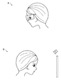
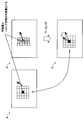
- FIG. 1 is an explanatory diagram for explaining an information processing method according to the present embodiment, and shows an application example of the information processing method according to the present embodiment.
- FIG. 1A shows an example in which the imaging device is provided in a wearable device that is used by being mounted on the head to be detected. That is, A in FIG. 1 illustrates an example in which the imaging device is fixed at a predetermined position with respect to the detection target.
- the information processing apparatus according to the present embodiment Obtain a polarized image from the device.
- the wearable device that is used by being mounted on the head to be detected include a glasses-type wearable device (eyewear) as shown in FIG. 1A, an HMD (Head Mounted Display), and the like.
- various images such as images related to UI (User Interface) are displayed on the display screen of the display device included in the wearable device.
- FIG. 1B shows an example in which the imaging device is provided in the environment.
- various images are displayed on the display screen of the display device provided in the environment. That is, B in FIG. 1 illustrates an example in which the imaging device is fixed at a predetermined position with respect to the display device.
- the information processing apparatus according to the present embodiment Obtain a polarized image from the device.
- the information processing apparatus for example, a wearable apparatus as shown in FIG. 1A, a display device as shown in FIG. 1B, or a PC (Personal) Computer) or a computer such as a server.
- the information processing apparatus according to the present embodiment is not limited to the example described above. Other application examples of the information processing apparatus according to the present embodiment will be described later.
- the polarized image is obtained, for example, by imaging with an imaging device provided in a wearable apparatus as shown in FIG. 1A or imaging with an imaging device provided in an environment as shown in FIG.
- the imaging device may be a stereo camera that captures a stereo image.
- the imaging device according to the present embodiment is a stereo camera
- the first polarization image corresponding to the right eye image (or the first polarization image corresponding to the left eye image) and the left eye are captured by the stereo camera.
- Two polarized images constituting a stereo image, ie, a second polarized image corresponding to the image (or a second polarized image corresponding to the right eye image) are obtained.
- Polarized images can be obtained by, for example, “installing a polarizing plate in front of the lens of the imaging device (subject side when viewed from the lens) and rotating the installed polarizing plate and imaging multiple times”, “for each pixel of the imaging device. On the other hand, it is obtained by arranging polarizing filters having different polarization angles and imaging once.
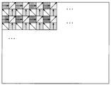
- FIG. 2 is an explanatory diagram showing an example of a polarization image acquisition method according to the present embodiment, and shows an example of a polarization filter arranged for each pixel of the imaging device.
- FIG. 2 shows an example in which polarization filters having four types of polarization angles of 0 [degree], 45 [degree], 90 [degree], and 135 [degree] are arranged for each pixel.
- the imaging device by performing imaging through a plurality of polarizing filters having different polarization angles as shown in FIG. 2, the imaging device generates a polarization image.
- the example of the polarizing filter which concerns on this embodiment is not restricted to the example shown in FIG. 2, and the acquisition method of a polarization image is not restricted to the method using a polarizing filter.
- the information processing apparatus obtains a normal line based on, for example, a polarization image obtained by imaging through a plurality of polarization filters as shown in FIG.
- the information processing apparatus for example, fits the light intensity indicated by the polarization image (the intensity obtained through a plurality of polarization filters) to a cosine curve, and specifies the normal vector of each pixel, thereby determining the normal line. obtain.
- the information processing apparatus obtains a luminance image (or an RGB image when an RGB filter is further used by taking an average of polarized images captured through a plurality of polarizing filters. It is possible to obtain
- the normal vector of each pixel is expressed by an azimuth angle and a zenith angle.
- FIG. 3 is an explanatory diagram for explaining the information processing method according to the present embodiment, and shows an example of the azimuth angle and the zenith angle corresponding to the normal vector.
- the azimuth angle can be calculated from the phase of the cosine curve, and the zenith angle can be calculated from the amplitude of the cosine curve.
- the azimuth angle has an indefiniteness of 180 degrees. Therefore, the normal vector at a certain position of the subject may not be uniquely specified.
- FIG. 4 is an explanatory diagram for explaining the information processing method according to the present embodiment, and shows an example in the case where the normal vector is not uniquely specified due to indefinite azimuth angle.
- the information processing apparatus specifies a normal corresponding to the cornea from a plurality of normals obtained from the polarization image, based on the detected position of the pupil in the eye.
- the information processing apparatus estimates a normal corresponding to the cornea based on the detected position of the pupil in the eye and the shape of the cornea.
- the information processing apparatus can obtain the normal corresponding to the cornea in the detection target eye based on the polarization image obtained by using the polarization imaging technique.
- the information processing apparatus estimates the center position of the cornea in the eye to be detected based on the normal line obtained from the polarization image.
- the information processing apparatus estimates the central position of the cornea in the eye based on, for example, the normal corresponding to the obtained cornea.
- the information processing apparatus estimates the center position of the cornea based on the normal corresponding to the cornea obtained based on the polarization image. That is, in the information processing apparatus according to the present embodiment, it is not necessary to estimate the center position of the cornea using the Purkinje image as in the case where the corneal reflection method is used.
- the information processing apparatus causes a negative effect as in the case of detecting the line of sight using the cornea reflection method by performing the detection process as the process related to the information processing method according to the present embodiment. Without doing so, it is possible to detect the line of sight of the detection target.
- the imaging device is a stereo camera
- the information processing apparatus is based on normal lines obtained from the first polarization image and the second polarization image that form the stereo image. Then, the line of sight to be detected is detected. As will be described later, the information processing apparatus according to the present embodiment estimates the center position of the cornea in the detection target eye based on the normals obtained from the first polarization image and the second polarization image, respectively. Detecting the line of sight of the detection target.
- the information processing apparatus detects the line of sight using the corneal reflection method even when the detection process is performed based on the first polarization image and the second polarization image forming the stereo image. It is possible to detect the line of sight of the detection object without causing the harmful effects as in the case.
- the information processing apparatus performs “detection processing for detecting a line of sight to be detected based on a normal obtained from a polarization image”.
- the information processing apparatus estimates the central position of the cornea in the eye based on the normal obtained from the polarization image, and detects the line of sight to be detected.
- the information processing apparatus estimates the center position of the cornea based on the normal corresponding to the cornea estimated based on the polarization image.
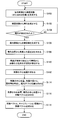
- FIG. 5 is a flowchart showing an example of processing related to the information processing method according to the present embodiment.
- the information processing apparatus generates a luminance image (or RGB image) from the polarization image (S100).
- a luminance image is generated by taking an average of polarized images captured through a plurality of polarizing filters.
- the information processing apparatus according to the present embodiment can further generate an RGB image by applying an RGB filter.
- a luminance image is generated in step S100.
- the information processing apparatus detects the pupil in the detection target eye from the luminance image (S102).
- the information processing apparatus detects the pupil from the luminance image by, for example, machine learning using dictionary data for pupil detection.
- the information processing apparatus determines whether or not a pupil is detected from the luminance image (S104).
- a pupil is detected from the luminance image (S104).
- the polarization image obtained by imaging with the imaging device is not the polarization image in which the detection target eye is captured.
- the pupil is determined in step S104 that the pupil has been detected from the luminance image, this corresponds to the case where the polarization image obtained by imaging with the imaging device is a polarization image in which the eye to be detected is imaged.
- step S104 If it is not determined in step S104 that a pupil has been detected from the luminance image, the information processing apparatus according to the present embodiment repeats the processing from step S100, for example.
- the information processing apparatus If it is determined in step S104 that a pupil has been detected from the luminance image, the information processing apparatus according to the present embodiment generates, for example, a normal image from the polarization image (S106).
- the normal image is an image represented by a normal vector specified in each pixel of the polarization image, for example. That is, the process in step S106 corresponds to a process for obtaining a normal line in each pixel of the polarization image.
- the information processing apparatus obtains the closest point on the cornea from the pupil position based on the detection result of the pupil in step S102 and the normal image generated in step S106 (S108).
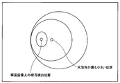
- FIG. 6 is an explanatory diagram for explaining an example of processing related to the information processing method according to the present embodiment, and shows an example of the closest point on the cornea.
- the closest point on the cornea is a point corresponding to a position on the cornea having the smallest zenith angle, for example.
- the processing in step S108 corresponds to processing for estimating a normal corresponding to the cornea based on the position of the pupil in the eye detected based on the polarization image and the normal obtained from the polarization image.
- the information processing apparatus is based on information indicating that the eye to be detected can be regarded as a sphere, that is, the cornea can be regarded as a sphere (or the cornea can be regarded as a convex sphere). Indefiniteness is removed (S110).
- FIG. 7 is an explanatory diagram for explaining an example of processing related to the information processing method according to the present embodiment, and shows an example of a normal vector after removing ambiguity indefiniteness.
- the information processing apparatus estimates the center position of the cornea (S112).
- the center position of the cornea is represented by, for example, three-dimensional coordinates.
- the information processing apparatus performs, for example, any one of the processing according to the first example shown in (1) below to the processing according to the fourth example shown in (4).
- the center position of the cornea is estimated.
- First example of processing related to estimation of center position of cornea first example of estimation based on a plurality of normals on cornea
- An information processing apparatus includes, for example, a plurality of processing on a cornea Based on the normal, the central position of the cornea is estimated.
- the information processing apparatus obtains, for example, the nearest point of a plurality of normals on the cornea and uses the found nearest point as the center position of the cornea.
- the information processing apparatus obtains the nearest points of a plurality of normals on the cornea based on the radius of the cornea, for example.
- the radius of the cornea used by the information processing apparatus according to the present embodiment for estimating the center position of the cornea may be a preset fixed value, or the fixed value is adjusted by an adjustment value corresponding to the detection target. It may be a variable value.
- the information processing apparatus according to this embodiment for example, “recognition result of detection target specified by any method such as biometric authentication and password authentication” and “detection target and The adjustment value corresponding to the detection target is specified based on the table (or database, hereinafter the same shall apply) in which the adjustment value is associated.
- Second example of processing related to estimation of center position of cornea second example of estimation based on a plurality of normals on cornea
- An information processing apparatus includes, for example, a plurality of processing on the cornea Based on the normal, the central position of the cornea is estimated.
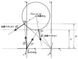
- FIG. 8 is an explanatory diagram for explaining an example of processing related to the information processing method according to the present embodiment.
- FIG. 8 shows an example in which the center position of the cornea is estimated based on two normals on the cornea.
- the normal vector on the cornea point G1 is N1
- the normal vector on the cornea point G2 is N2
- the center of the imaging device The vector from the position O toward the point G2 on the cornea is I2
- the distance between the center position O of the imaging device and the point G1 on the cornea is d1
- the distance between the center position O of the imaging device and the point G2 on the cornea Let the distance be d2.
- the distance d1 between the center position O of the imaging device and the point G1 on the cornea is referred to as “distance d1”
- the distance d2 between the center position O of the imaging device and the point G2 on the cornea is referred to as “distance”.
- d2 in some cases.
- the coordinates of the center position C of the cornea, the distance d1 between the center position O of the imaging device and the point G1 on the cornea, and the distance d2 between the center position O of the imaging device and the point G2 on the cornea Is unknown.
- the distance d1 between the center position O of the imaging device and the point G1 on the cornea is referred to as “distance d1”
- the distance d2 between the center position O of the imaging device and the point G2 on the cornea is referred to as “distance”.
- d2 in some cases.
- the information processing apparatus sets the coordinates of the center position C of the cornea, the distance d1 and the distance d2 as unknown, and solves the following mathematical formula 1 for the distance d1 and the distance d2 to thereby determine the center position C of the cornea.
- Equation 1 since each vector represented by Equation 1 has an x coordinate component, a y coordinate component, and a z coordinate component, Equation 1 corresponds to a nonlinear simultaneous equation.
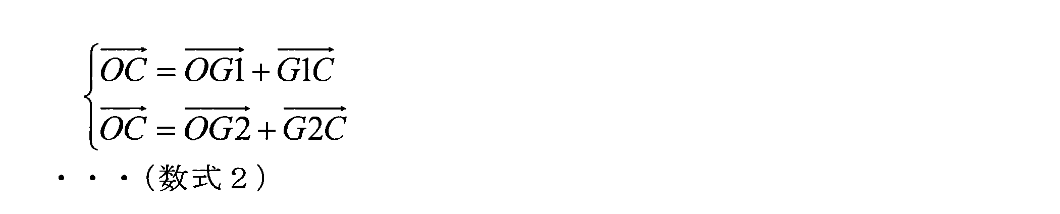
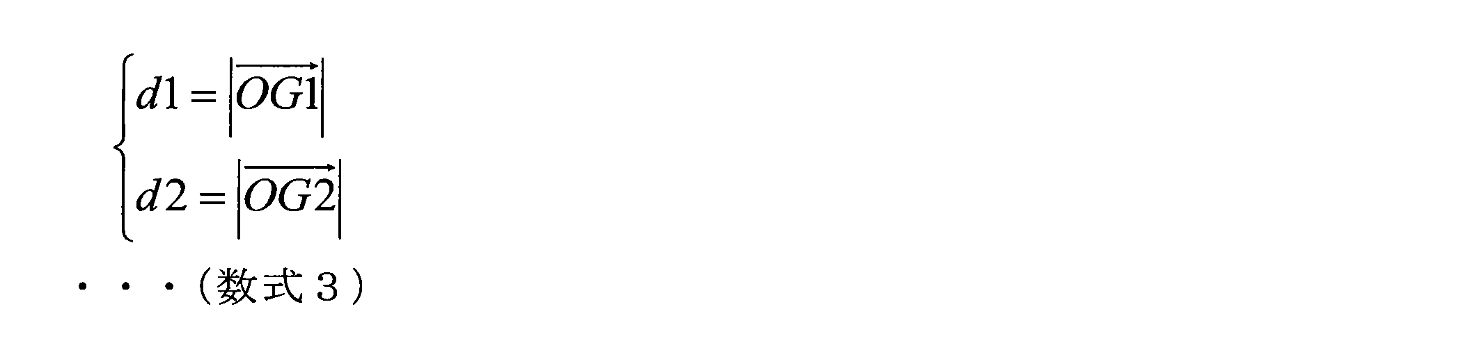
- a vector from the center position O of the imaging device to the center position C of the cornea is expressed by the following formula 2, and the distance d1 and the distance d2 are expressed by the following formula 3.
- the information processing apparatus obtains the position of the point G1 on the cornea and the position of the point G2 on the cornea based on the distance d1 and the distance d2 obtained from the expression 1 and the expression 3.
- the information processing apparatus includes the position of the point G1 on the cornea, the normal vector N1 on the point G1 on the cornea, the position of the point G2 on the cornea, and the normal vector on the point G2 on the cornea.
- the coordinates of the center position C of the cornea are obtained from N2 and the cornea radius r.
- the information processing apparatus can estimate the center position of the cornea based on two normals on the cornea as described above, for example.
- the information processing apparatus When there are N normal lines on the cornea (N is an integer of 3 or more), for example, the information processing apparatus according to the present embodiment expands Equation 1 to N normal lines, and N By determining the number of unknowns, the coordinates of the central position C of the cornea can be determined in the same manner as in the case based on the two normals on the cornea.
- N is an integer of 3 or more
- the information processing apparatus is based on the normal obtained from each of the first polarization image and the second polarization image forming the stereo image, and the center position of the cornea in the detection target eye. It is also possible to estimate
- the information processing apparatus uses the first polarization image and the second polarization image. To obtain the parallax. Then, the information processing apparatus according to the present embodiment estimates the center position of the cornea using the obtained parallax.
- FIG. 9 is a flowchart for explaining an example of processing related to the information processing method according to the present embodiment, and shows an example of processing for obtaining parallax based on the first polarization image and the second polarization image.
- the information processing apparatus generates a luminance image from the first polarization image and generates a luminance image from the second polarization image, similarly to step S100 of FIG. 5 (S200).
- first luminance image the luminance image generated from the first polarized image
- second luminance image the luminance image generated from the second polarized image
- the information processing apparatus does not perform the process of step S200, but corresponds to the luminance image and the second polarized image corresponding to the first polarization image generated by the process of step S100 of FIG. It is also possible to use the luminance image to be used for the processing after step S202.
- the information processing apparatus estimates the normal direction from each of the first polarization image and the second polarization image (S202).
- the information processing apparatus according to the present embodiment estimates the normal direction from each of the first polarization image and the second polarization image, for example, by performing the same processing as step S106 in FIG.
- a normal image generated from the first polarization image is referred to as a “first normal image”
- a normal image generated from the second polarization image is referred to as a “second normal image”. .
- the information processing apparatus can use the result of the process of step S106 in FIG. 5 for the processes after step S204 without performing the process of step S202.
- the information processing apparatus performs parallel processing on a luminance image corresponding to a stereo image (first polarization image and second polarization image; hereinafter the same) and a normal image corresponding to the stereo image. (S204).
- the information processing apparatus for example, warps the first luminance image and the second luminance image so that the normal lines of the corresponding pixels are matched, thereby luminance corresponding to the stereo image.
- the information processing apparatus according to the present embodiment for example, performs a stereo image by warping the first normal image and the second normal image so that the normal lines of the corresponding pixels match.
- the normal image corresponding to is parallelized. An example of warping will be described later.
- the information processing apparatus includes a first luminance image and a second luminance image based on a luminance image corresponding to a stereo image and normal information indicating a normal obtained from the normal image corresponding to the stereo image.
- a feature amount (hereinafter referred to as a “matching feature amount”) for matching with the luminance image is calculated (S206).
- the matching feature amount is calculated, for example, for a plurality of corresponding pixels in the stereo image.
- AD Absolute Difference
- SAD Sum Of Absolute Difference
- NCC Normalized Cross-Correlation
- Census Transform Long Term Evolution
- LBP Local Binary Pattern
- an existing technique for obtaining a feature value for matching such as “AD” is processing related to matching mainly using texture. For this reason, when only the existing method for obtaining the feature quantity for matching is used, for example, when a subject with less texture is captured by a stereo camera, the first luminance image and the second luminance image cannot be matched. Can happen.
- the information processing apparatus calculates a feature amount for matching based on a score obtained by using normal line information. Further, as will be described later, the information processing apparatus according to the present embodiment is further based on one or more scores obtained by using one or two or more existing techniques for obtaining the matching feature amount. Thus, it is also possible to calculate the feature quantity for matching.
- the information processing apparatus calculates a matching feature amount using, for example, Equation 4 below.
- “Matching Score” shown in Formula 4 corresponds to the feature quantity for matching.
- “ScoreA” shown in Equation 4 indicates a score obtained by a method for obtaining one existing matching feature amount, and “a” shown in Equation 4 is a coefficient that defines weighting for “ScoreA”.
- “ScoreB” shown in Formula 4 indicates a score obtained by another method for obtaining a feature value for matching, and “b” shown in Formula 4 is a coefficient that defines weighting for “ScoreB”.
- “ScoreC” shown in Formula 4 indicates a score obtained by using the normal line information, and “c” shown in Formula 4 is a coefficient that defines a weight for “ScoreC”.
- each of the coefficients “a”, “b”, and “c” shown in Expression 4 may be a fixed value set in advance, or may be changed by an operation of the user of the information processing apparatus according to the present embodiment. Possible variable values may be used. One or both of the coefficient “a” and the coefficient “b” shown in Formula 4 may be 0 (zero).
- the mathematical formula for calculating the feature quantity for matching is not limited to the mathematical formula 4 described above.
- the information processing apparatus according to the present embodiment can calculate a matching feature amount by using a score obtained by a method of obtaining three or more existing matching feature amounts.
- Score A is a score obtained by “Census Transform” and Score B is a score obtained by “AD”.
- An example is shown.
- an example of a score calculation method using normal line information is shown.
- FIG. 10 is an explanatory diagram for explaining an example of a method for calculating a feature value for matching according to the present embodiment, and shows an example of a score calculation method using “Census Transform”.
- a shown in FIG. 10 indicates a luminance image (first luminance image or second luminance image) corresponding to the left eye
- B shown in FIG. 10 indicates a luminance image (second luminance image) corresponding to the right eye. Or a first luminance image).
- the magnitude relationship between the target pixel and the other pixels in the luminance image corresponding to the left eye is It is expressed as 10D and is bit-patterned as shown in E of FIG.
- a feature amount of 24 [bits] is generated.
- a feature amount can be obtained similarly for a target pixel in a luminance image corresponding to the right eye.
- the target pixel in the luminance image corresponding to the right eye is identified by searching for pixels on the same line in the luminance image corresponding to the right eye, for example, with reference to the target pixel in the luminance image corresponding to the left eye. Is done.
- the hamming distance between the feature amount of the target pixel based on the luminance image corresponding to the left eye and the feature amount of the target pixel based on the luminance image corresponding to the right eye is calculated, and the calculated Hamming The distance is taken as the score.
- step S204 of FIG. 9 when the luminance image corresponding to the stereo image is parallelized, the feature amount and score of the patch centered on the target pixel are calculated, and the stereo image is converted into the stereo image.
- the warping is performed so that the normal direction of the corresponding luminance image matches, and the feature amount and score of the patch are calculated.
- FIG. 11 is an explanatory diagram for explaining an example of a method for calculating a feature amount for matching according to the present embodiment, and shows an example in which warping is performed using one normal line.
- a shown in FIG. 11 indicates a luminance image corresponding to the left eye (first luminance image or second luminance image)
- B shown in FIG. 11 indicates a luminance image corresponding to the right eye (second luminance image). Or a first luminance image).
- C shown in FIG. 11 represents a luminance image corresponding to the right eye on which warping has been performed.
- a score is calculated by “Census Transform” based on the luminance image corresponding to the left eye and the luminance image corresponding to the right eye warped as shown in FIG. It is possible to calculate a feature amount for matching that can obtain a high parallax.
- FIG. 11 shows an example in which warping is performed using one normal line, but in consideration of the above-described ambiguity of azimuth, warping is performed twice using two normal lines, It is also possible to employ a smaller value (or a larger value) after calculating the feature amount and the score, respectively.
- FIG. 12 is an explanatory diagram for explaining an example of a method for calculating a feature value for matching according to the present embodiment, and shows an example of a score calculation method using “AD”.
- a in FIG. 12 indicates a luminance image (first luminance image or second luminance image) corresponding to the left eye
- B in FIG. 12 indicates a luminance image (second luminance image) corresponding to the right eye. Or a first luminance image).
- AD the pixel value of each pixel of interest in the luminance image corresponding to the stereo image is used as the feature amount.
- AD the absolute value of the difference between the pixel values of the target pixel is used as a score.
- FIG. 13 is an explanatory diagram for explaining an example of a method for calculating a matching feature amount according to the present embodiment, and shows an example of a score calculation method using normal line information.
- a shown in FIG. 13 indicates a luminance image corresponding to the left eye (first luminance image or second luminance image), and B shown in FIG. 13 indicates a luminance image corresponding to the right eye (second luminance image). Or a first luminance image).
- the reason why there are two normals in the pixel of interest is that the azimuth angle is indefinite as described above. Since there are 4 (2 ⁇ 2) combinations for calculating the inner product, it is also possible to take inner products corresponding to the four combinations. However, as described above, even when the normal line in one image is fixed and the inner product between two normal lines in the other normal line is calculated, a sufficiently accurate score can be obtained. .
- the information processing apparatus calculates a matching feature amount by performing, for example, the calculation shown in Equation 4 above in step S206 of FIG.
- the information processing apparatus calculates the likelihood of image matching in the stereo image based on the matching feature amount calculated in step S206, and the parallax at the position of the pixel with the highest likelihood in the stereo image. Is obtained (S208).
- the information processing apparatus obtains the parallax based on the first polarization image and the second polarization image, for example, by performing the processing shown in FIG. Needless to say, the example of the process for obtaining the parallax based on the first polarization image and the second polarization image is not limited to the example shown in FIG.
- FIG. 14 is an explanatory diagram for explaining an example of processing related to the information processing method according to the present embodiment.
- FIG. 14 shows an example in which the center position of the cornea is estimated based on two normals on the cornea and the parallax.
- the center position (camera center) of one imaging device constituting the stereo camera is the origin O of the coordinate system
- the cornea radius is r
- the point on the cornea is G1
- the normal vector on the point G1 on the cornea is N1
- the normal vector on the point G2 on the cornea is N2
- the vector from the center position O of one imaging device to the point G1 on the cornea is I1
- a vector from the center position O of the imaging device to the point G2 on the cornea is I2
- a distance between the center position O of the one imaging device and the point G1 on the cornea is d1
- the center position O of the one imaging device and the cornea The distance between the upper point G2 is d2.
- distance d1 between the center position O of one imaging device and the point G1 on the cornea is referred to as “distance d1”, and the distance between the center position O of one imaging device and the point G2 on the cornea d2 may be indicated as “distance d2”.
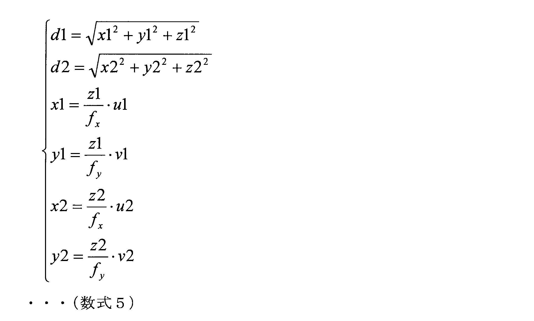
- “Z1” corresponding to the z-coordinate of the point G1 on the cornea and “z2” corresponding to the z-coordinate of the point G2 on the cornea are obtained by the parallax obtained by the process (3-1).
- the information processing apparatus calculates the distance d1 and the distance d2 by performing the calculation shown in the following Expression 5.
- “f x ” shown in Formula 5 indicates the x direction of Focal Length, which is one of the internal parameters of the imaging device
- “f y ” shown in Formula 5 indicates the y direction of Focal Length.
- (u1, v1) shown in Equation 5 indicates the coordinates on the image of the point G1 on the cornea
- (u2, v2) shown in Equation 5 indicates the coordinates on the image of the point G2 on the cornea.
- Show. “U1”, “v1”, “u2”, and “v2” shown in Formula 5 are expressed in units [pix], for example.
- the information processing apparatus When the distance d1 and the distance d2 are calculated, the information processing apparatus according to the present embodiment obtains the cornea radius r by the above mathematical formula 1 and obtains the coordinates of the central position C of the cornea.
- the information processing apparatus includes a position of the point G1 on the cornea, a normal vector N1 on the point G1 on the cornea, a position of the point G2 on the cornea, a normal vector N2 on the point G2 on the cornea, And the coordinates of the central position C of the cornea are obtained from the cornea radius r obtained by the above mathematical formula 1.
- the information processing apparatus can estimate the center position of the cornea using parallax, for example, as described above.
- the information processing apparatus When there are N normal lines on the cornea (N is an integer equal to or greater than 3), the information processing apparatus according to the present embodiment, for example, expands Equation 1 to N normal lines. Similarly to the case based on the two normals on the cornea, the coordinates of the central position C of the cornea can be obtained.
- the information processing apparatus obtains, for example, center coordinates of the cornea from M (minimum two) normal vectors, and re-projects a sphere with a radius r centered on the obtained center coordinates of the cornea onto an image. To do.
- the information processing apparatus calculates the inner product of the normal on the sphere and the normal obtained from the polarization image, and counts the number of normals exceeding the set threshold. Then, the information processing apparatus according to the present embodiment obtains the center coordinates of the sphere by optimization using the normal line having the largest number, and estimates the center position of the cornea.
- FIG. 15 is a flowchart for explaining an example of processing related to the information processing method according to the present embodiment, and shows an example of processing for estimating the center position of the cornea using RANSAC.
- the information processing apparatus calculates the coordinates of the central position of the cornea as the nearest point of the M normal vectors, for example, similarly to the process according to the first example shown in (1) above (S300). ).
- the information processing apparatus re-projects the surface of a sphere having a radius r around the coordinates calculated in step S300 onto a luminance image based on the polarization image (S302).
- the radius r corresponds to the radius of the cornea.
- the radius r may be a fixed value set in advance, or may be a variable value in which the fixed value is adjusted by an adjustment value corresponding to the detection target.
- the information processing apparatus calculates the inner product of the normal on the sphere and the normal obtained from the polarization image, and counts the number of normals exceeding the set threshold (S304).
- the threshold value may be a fixed value set in advance, or may be a variable value that can be changed by a user operation of the information processing apparatus according to the present embodiment.
- the information processing apparatus determines whether or not the number of normals counted in step S304 exceeds the maximum value (S306).
- the initial value of the maximum value includes a set value such as 0 (zero).
- the number of counted normals is It is determined that the set maximum value has been exceeded.
- step S306 If it is not determined in step S306 that the maximum value has been exceeded, the information processing apparatus according to the present embodiment performs processing from step S310 described later.
- step S306 If it is determined in step S306 that the maximum value has been exceeded, the information processing apparatus according to the present embodiment updates the maximum value to the number of counted normals, and the method exceeds the set threshold.
- the position of the line is stored in a recording medium such as a RAM (Random Access Memory) (S308).
- step S306 If it is not determined in step S306 that the maximum value has been exceeded, or if the process in step S308 is performed, the information processing apparatus according to the present embodiment performs the process L times (L is a set integer). It is determined whether it has been performed (S310).
- L may be a fixed value set in advance, or may be a variable value that can be changed by an operation of a user of the information processing apparatus according to the present embodiment.
- step S310 If it is not determined in step S310 that the processing has been performed L times, the information processing apparatus according to the present embodiment repeats the processing from step S300.
- step S310 If it is determined in step S310 that the processing has been performed L times, the information processing apparatus according to the present embodiment, for example, “has a radius r centered on the central coordinates of the cornea reprojected in step S302.
- the central coordinates of the cornea that maximize the “sum of inner products of the normal of the sphere and the normal stored in the recording medium in step S308” are obtained by optimization (S312).
- the information processing apparatus estimates the center position of the cornea by performing, for example, the processing shown in FIG. Needless to say, the processing related to the estimation of the center position of the cornea using RANSAC is not limited to the example shown in FIG.
- step S112 of FIG. 5 the information processing apparatus according to the present embodiment performs any one of the processes from the first example shown in (1) to the fourth example shown in (4), for example. To estimate the center position of the cornea.
- the information processing apparatus estimates the center position of the pupil in the eye based on the estimated center position of the cornea and the radius of the cornea (S114).
- the information processing apparatus uses the inter-pupil distance in the cornea, for example, similarly to the case where the corneal reflection method is used, and considers refraction and the like to determine the center position of the pupil. presume.
- the information processing apparatus uses the light indicating the optical axis corresponding to the line of sight to be detected based on the central position of the cornea estimated in step S112 and the central position of the pupil estimated in step S114.
- An axis vector is obtained (S116).
- the optical axis is a corneal normal passing through the center position of the pupil, and corresponds to, for example, a line connecting the center position of the cornea and the center position of the pupil.
- the information processing apparatus obtains the optical axis vector as in the case where the corneal reflection method is used, for example.
- the information processing apparatus obtains a line-of-sight vector indicating the visual axis to be detected based on the optical axis vector obtained in step S116 and the calibration information (S118).
- the visual axis is a line connecting the nodal point (the central rear surface of the crystalline lens) and the fovea and corresponds to the axis that is actually viewed by the detection target. That is, the line of sight to be detected is detected by obtaining the line-of-sight vector.
- the visual axis and the optical axis generally do not coincide with each other, and the visual axis is inclined by about 4 [°] to 8 [°] with respect to the optical axis. Further, there are individual differences in how the visual axis is tilted with respect to the optical axis.
- the optical axis vector is corrected (hereinafter referred to as “calibration”) based on the calibration information.
- the calibration is performed for each eye to be detected, for example.
- the calibration information is data for performing calibration.
- the calibration information includes data indicating a visual axis shift (hereinafter referred to as “offset”) with respect to the optical axis.
- the offset is obtained as follows, for example.
- the calibration position is viewed by the detection target, and the difference between the optical axis vector obtained at that time and the vector connecting the calibration position and the reference position corresponding to the eyeball is obtained as an offset.
- the information processing apparatus performs, for example, the processing illustrated in FIG. 5 as the detection processing according to the information processing method according to the present embodiment, thereby detecting the line of sight of the detection target based on the normal obtained from the polarization image. Is detected.
- the example of the detection process according to the information processing method according to the present embodiment is not limited to the example shown in FIG.
- processing related to information processing method according to the present embodiment is based on “the gaze of the detection target based on the normal obtained from the polarization image”. It is not limited to “detection processing to detect”.
- the information processing apparatus performs “a process for detecting various things other than the line of sight based on a normal obtained from a polarization image” (hereinafter, referred to as “other detection process”). It is possible.
- other detection processing for example, a first example shown in the following (I) to a fourth example shown in (IV) can be given.
- the information processing apparatus detects the center position of the cornea in the detection target eye based on, for example, a normal line obtained from a polarization image.
- the information processing apparatus detects the center position of the cornea, for example, by performing the processes of steps S100 to S112 in FIG.
- the information processing apparatus is indicated by the information indicating the shape based on, for example, the normal obtained from the polarization image and the information indicating the shape of the object.
- One or both of the posture of the object and a change in the posture of the object are detected.
- the information processing apparatus detects the posture of the object by, for example, estimating the posture of the object indicated by the information indicating the shape based on a combination of normals obtained from the polarization image.
- the information processing apparatus for example, changes the posture of the object indicated by the shape information by comparing combinations of normals obtained from a plurality of polarization images obtained by imaging at different time points. Is detected, a change in the posture of the object is detected.
- the information processing apparatus can further detect the position (three-dimensional position) of the object in the space based on the distance between the object indicated by the information indicating the shape and the imaging device. It is.
- the distance between the object and the imaging device is detected by a distance sensor that detects the distance by an arbitrary method such as TOF (Time Of Flight).
- the information processing apparatus includes, for example, an imaging device among objects (subjects) captured by the imaging device based on a normal obtained from a polarization image. An object facing a predetermined direction with respect to is detected.
- the information processing apparatus specifies, for example, a region included in a range of angles in which a normal vector obtained from a polarization image is set in a luminance image (or RGB image) based on the polarization image. Then, the information processing apparatus according to the present embodiment detects an object facing a predetermined direction with respect to the imaging device by performing object recognition processing according to an arbitrary object recognition technique on the specified region. To do.
- an arbitrary object such as a sign or a kanban is detected based on a polarization image captured by an imaging device mounted on a moving body such as an automobile.
- An example is given.
- the information processing apparatus matches, for example, a combination of normals obtained from a polarization image and a combination of normals indicated by information indicating the combination of normals. Then, the information processing apparatus according to the present embodiment detects, for example, a region of a normal line by detecting a region in which a combination of normal lines matches in a polarization image (or a luminance image (or RGB image) based on the polarization image). The object indicated by the information indicating the combination is detected from the polarization image.
- a combination of normals due to a difference in diffuse reflection and specular reflection caused by different materials is used, and a counterfeit product is used.
- the processing load related to the object recognition process can be reduced.
- FIG. 16 is a block diagram illustrating an example of the configuration of the information processing apparatus 100 according to the present embodiment.
- the information processing apparatus 100 includes, for example, an imaging unit 102 and a control unit 104.
- the information processing apparatus 100 is, for example, a ROM (Read Only Memory) (not shown), a RAM (not shown), a storage unit (not shown), or a communication for performing wireless or wired communication with an external device.
- a display unit (not shown) that displays various screens on a display screen, and the like.
- the information processing apparatus 100 connects the above constituent elements by, for example, a bus as a data transmission path.
- the information processing apparatus 100 connects the above constituent elements by, for example, a bus as a data transmission path.
- the information processing apparatus 100 is driven by, for example, power supplied from an internal power source such as a battery provided in the information processing apparatus 100 or power supplied from a connected external power source.
- a ROM (not shown) stores control data such as a program used by the control unit 104 and calculation parameters.
- a RAM (not shown) temporarily stores a program executed by the control unit 104.
- the storage unit (not shown) is a storage unit included in the information processing apparatus 100.
- data related to the information processing method according to the present embodiment such as dictionary data and calibration information, image data indicating a polarization image, Stores various data such as applications.
- examples of the storage unit include a magnetic recording medium such as a hard disk, a non-volatile memory such as a flash memory, and the like. Further, the storage unit (not shown) may be detachable from the information processing apparatus 100.
- Examples of the communication unit include a communication interface described later.
- the operation input device mentioned later is mentioned, for example.
- the display device mentioned later is mentioned, for example.
- FIG. 17 is an explanatory diagram illustrating an example of a hardware configuration of the information processing apparatus 100 according to the present embodiment.
- the information processing apparatus 100 includes, for example, an MPU 150, a ROM 152, a RAM 154, a recording medium 156, an input / output interface 158, an operation input device 160, a display device 162, a communication interface 164, and an imaging device 166.
- the information processing apparatus 100 connects each component with a bus 168 as a data transmission path, for example.
- the MPU 150 includes, for example, one or more processors configured with arithmetic circuits such as an MPU (Micro Processing Unit) and various processing circuits, and functions as the control unit 104 that controls the entire information processing apparatus 100. . Further, the MPU 150 plays a role of, for example, the processing unit 110 described later in the information processing apparatus 100.
- MPU Micro Processing Unit
- the ROM 152 stores programs used by the MPU 150, control data such as calculation parameters, and the like.
- the RAM 154 temporarily stores a program executed by the MPU 150, for example.
- the recording medium 156 functions as a storage unit (not shown).
- data related to the information processing method according to the present embodiment such as dictionary data and calibration information, image data indicating a polarization image, applications, and the like are various. Memorize data.
- Examples of the recording medium 156 include a magnetic recording medium such as a hard disk and a non-volatile memory such as a flash memory. Further, the recording medium 156 may be detachable from the information processing apparatus 100.
- the input / output interface 158 connects, for example, the operation input device 160 and the display device 162.
- the operation input device 160 functions as an operation unit (not shown)
- the display device 162 functions as a display unit (not shown).
- examples of the input / output interface 158 include a USB (Universal Serial Bus) terminal, a DVI (Digital Visual Interface) terminal, an HDMI (High-Definition Multimedia Interface) (registered trademark) terminal, and various processing circuits. .
- the operation input device 160 is provided on the information processing apparatus 100, for example, and is connected to the input / output interface 158 inside the information processing apparatus 100.
- Examples of the operation input device 160 include a button, a direction key, a rotary selector such as a jog dial, or a combination thereof.
- the display device 162 is provided on the information processing apparatus 100, for example, and is connected to the input / output interface 158 inside the information processing apparatus 100.
- Examples of the display device 162 include a liquid crystal display (Liquid Crystal Display), an organic EL display (Organic Electro-Luminescence Display, or an OLED display (Organic Light Emitting Diode Display)), and the like.
- the input / output interface 158 can be connected to an external device such as an operation input device (for example, a keyboard or a mouse), a display device, or an imaging device as an external device of the information processing apparatus 100.
- an operation input device for example, a keyboard or a mouse
- a display device for example, a liquid crystal display
- an imaging device as an external device of the information processing apparatus 100.
- the display device 162 may be a device capable of display and user operation, such as a touch device.
- the communication interface 164 is a communication unit included in the information processing apparatus 100, and via a network (or directly) an external device such as an external imaging device or an external display device, an external device such as a server, It functions as a communication unit (not shown) for performing wireless or wired communication.
- Examples of the communication interface 164 include a communication antenna and an RF (Radio Frequency) circuit (wireless communication), an IEEE 802.15.1 port and a transmission / reception circuit (wireless communication), an IEEE 802.11 port and a transmission / reception circuit (wireless communication), or Examples include LAN (Local Area Network) terminals and transmission / reception circuits (wired communication).
- the communication unit (not shown) has a configuration corresponding to an arbitrary standard capable of communication such as a USB (Universal Serial Bus) terminal and a transmission / reception circuit, or an arbitrary communication capable of communicating with an external device via a network. It may be a configuration.
- an arbitrary standard capable of communication such as a USB (Universal Serial Bus) terminal and a transmission / reception circuit, or an arbitrary communication capable of communicating with an external device via a network. It may be a configuration.
- a wired network such as a LAN or a WAN (Wide Area Network), a wireless LAN (WLAN: Wireless Local Area Network) or a wireless WAN via a base station (WWAN: Wireless Wide Area Area).
- a communication protocol such as TCP / IP (Transmission Control Protocol / Internet Protocol).
- the imaging device 166 is an imaging unit included in the information processing apparatus 100, and functions as the imaging unit 102 that generates a polarization image by imaging.
- the information processing apparatus 100 can perform processing related to the information processing method according to the present embodiment based on, for example, a polarized image generated by imaging in the imaging device 166.
- the imaging device 166 includes, for example, a lens / imaging device and a signal processing circuit.
- the lens / imaging device includes, for example, an optical lens and an image sensor using a plurality of imaging devices such as a CMOS (Complementary Metal Oxide Semiconductor) and a CCD (Charge-Coupled Device).
- the signal processing circuit includes, for example, an AGC (Automatic Gain Control) circuit and an ADC (Analog to Digital Converter), and converts an analog signal generated by the image sensor into a digital signal (image data).
- the signal processing circuit performs various processes related to, for example, RAW development.
- the information processing apparatus 100 performs processing related to the information processing method according to the present embodiment, for example, with the configuration shown in FIG. Note that the hardware configuration of the information processing apparatus 100 according to the present embodiment is not limited to the configuration illustrated in FIG.
- the information processing apparatus 100 may not include the imaging device 166.
- the information processing apparatus 100 when the information processing apparatus 100 is configured to perform processing in a stand-alone manner, or when performing communication using an external communication device, the information processing apparatus 100 may not include the communication interface 164. Further, the information processing apparatus 100 may be configured not to include one or more of the recording medium 156, the operation input device 160, and the display device 162.
- the imaging unit 102 generates a polarization image by imaging.
- An example of the imaging unit 102 is an imaging device 166.
- the control unit 104 is configured by, for example, an MPU and plays a role of controlling the entire information processing apparatus 100.
- the control unit 104 includes, for example, a processing unit 110 and plays a role of leading the processing related to the information processing method according to the present embodiment.
- the processing unit 110 serves to lead the detection processing according to the present embodiment, and detects the line of sight to be detected based on the normal line obtained from the polarization image.
- the processing unit 110 detects the line of sight of the detection target based on the polarization image, for example, by performing the processing shown in FIG.
- processing unit 110 performs, for example, one or more of the other detection processes according to the first example shown in (I) to the other detection processes according to the fourth example shown in (IV). Can be done.
- the processing unit 110 may perform one or more of the other detection processes according to the first example shown in (I) to the other detection processes according to the fourth example shown in (IV). If possible, the information processing apparatus 100, for example, in addition to the function of performing the detection process according to the present embodiment, the other detection processes according to the first example shown in (I) to the fourth shown in (IV). A function of further performing one or more of the other detection processes according to the example.
- the information processing apparatus 100 performs processing related to the information processing method according to the present embodiment (for example, “detection processing” or “detection processing and other detection processing”) with the configuration illustrated in FIG. 16, for example. Therefore, the information processing apparatus 100 can detect the line of sight of the line-of-sight detection target, for example, with the configuration shown in FIG.
- the information processing apparatus 100 can exhibit the effects exhibited by performing the processing related to the information processing method according to the present embodiment as described above.
- the information processing apparatus can include the processing unit 110 illustrated in FIG. 16 separately from the control unit 104 (for example, realized by another processing circuit).
- the processing unit 110 may be realized by a plurality of processing circuits, and each function may be performed by a plurality of processing circuits in a distributed manner.
- the configuration for realizing the processing related to the information processing method according to the present embodiment is not limited to the configuration illustrated in FIG. 16, and takes a configuration according to the method of dividing the processing according to the information processing method according to the present embodiment. It is possible.
- the processing unit 110 performs one or more of the other detection processes according to the first example shown in (I) to the other detection processes according to the fourth example shown in (IV).
- the information processing apparatus according to the present embodiment may be configured not to have the function of performing the detection processing according to the present embodiment.
- the present embodiment when performing processing related to the information processing method according to the present embodiment based on a polarization image captured by an external imaging device having the same function and configuration as the imaging unit 102, the present embodiment Such an information processing apparatus may not include the imaging unit 102.
- the information processing apparatus has been described as the present embodiment, but the present embodiment is not limited to such a form.
- a wearable device used by being attached to a head to be detected such as eyewear as shown in FIG. 1A
- computer such as a PC or server
- communication such as a smartphone
- Various devices capable of performing processing related to the information processing method according to the present embodiment such as “device”, “display device”, “tablet-type device”, “game machine”, and “moving body such as an automobile”.
- the present embodiment can be applied to.
- the present embodiment can be applied to a processing IC that can be incorporated in the above-described device, for example.
- the information processing apparatus according to the present embodiment can be applied to various use cases to which line-of-sight detection such as the following use cases can be applied.
- the use cases to which the information processing apparatus according to this embodiment can be applied are not limited to the use cases shown below.
- the information processing apparatus according to the present embodiment may or may not include a display device as described above.
- operation input of a medical device may be performed by detecting the line of sight of a medical worker such as a doctor (an example of a detection target).
- a patient with a physical disability can reduce the difficulty of living activities.
- a detection target For example, the line of sight of the driver (an example of a detection target), for example, the navigation operation displayed on the display screen of the display device or the driver's gaze
- Information related to an object such as a building may be displayed on a display screen of a display device, or may be transmitted to a driver by voice.
- the driver can operate the device without using his / her hand, which can reduce the possibility of sidewalks and improve driving safety.
- the driver's driving level is determined by recording the driver's gaze destination on a recording medium and comparing the recorded driver's gaze destination with gaze data of a predetermined user model. It is possible.
- the driver's attention is determined by comparing the recorded driver's gaze destination with gaze data of a predetermined user model, and the driver is alerted by voice or the like.
- the proposal of a suitable form etc. may be performed by detecting the eyes
- a product to be recommended to a marketing target may be proposed by detecting the line of sight of a marketing target (an example of a detection target).
- the person engaged in agriculture for example, supplementary information on the state of the crop that the person engaged in agriculture is gazing at, the display screen of the display device, etc. It may be provided by a display.
- the line-of-sight detection result of an animal may be used.
- the detected line of sight with the model data of the line of sight, it is possible to estimate the birth time or poor physical condition of the animal.
- the sanitary condition in the stable may be estimated from the result of eye gaze detection of the animal in the stable.
- the information processing apparatus may be applied to a processing system that is premised on connection to a network (or communication between apparatuses), such as cloud computing.
- a processing system in which processing according to the information processing method according to the present embodiment is performed for example, “a part of processing according to the information processing method according to the present embodiment is performed by one apparatus configuring the processing system.
- a system in which processing other than the partial processing of the processing according to the information processing method according to the present embodiment is performed by another device that is included in the processing system.
- a program for example, “detection process” or “detection process and other detection process”) for causing a computer to function as the information processing apparatus according to the present embodiment is a process related to the information processing method according to the present embodiment. Is executed by a processor or the like in the computer, so that the line of sight of the line of sight can be detected.
- an effect produced by the processing related to the information processing method according to the above-described embodiment by executing a program for causing the computer to function as the information processing apparatus according to the present embodiment by a processor or the like in the computer. can be show
- the computer has a function of performing one or more of the other detection processes according to the first example shown in (I) to the other detection processes according to the fourth example shown in (IV).
- a program for causing a computer to function as an information processing apparatus according to a modification of the present embodiment that does not have the function of performing the detection process according to the present embodiment is executed by a processor or the like in a computer The effect produced by the other detection processing according to the information processing method according to the present embodiment described above can be achieved.
- a program for causing a computer to function as the information processing apparatus according to the present embodiment is provided.
- the present embodiment further includes a recording in which the program is stored.
- a medium can also be provided.
- An information processing apparatus comprising: a processing unit that detects a line of sight of a detection target based on a polarization image obtained by imaging an eye of a line of sight detection.
- a processing unit estimates a center position of a cornea in the eye based on the polarization image and detects a line of sight of the detection target.
- the processing unit estimates a center position of the cornea based on a position of a pupil in the eye detected based on the polarization image and the polarization image.
- the processing unit estimates a normal corresponding to the cornea based on a position of a pupil in the eye detected based on the polarization image and a normal obtained from the polarization image.
- Information processing device (8)
- the processor is Based on the estimated center position of the cornea and the radius of the cornea, the center position of the pupil in the eye is estimated, Based on the estimated center position of the cornea and the estimated center position of the pupil, an optical axis vector corresponding to the line of sight of the detection target is obtained, and the line of sight of the detection target is detected (5) to The information processing apparatus according to any one of (7).
- the processing unit estimates a central position of the cornea in the eye based on a normal line obtained from each of the first polarization image and the second polarization image, and detects a line of sight of the detection target. ).
- the processing unit estimates a corneal radius based on a normal line and a parallax obtained from the first polarized image and the second polarized image, respectively, and based on the estimated corneal radius, the center of the cornea in the eye
- the information processing apparatus according to (13), wherein the position is estimated.
- the information processing apparatus acquires the polarization image from an imaging device fixed at a predetermined position with respect to the detection target.
- the processing unit acquires the polarization image from an imaging device fixed at a predetermined position with respect to a display device.
- the information processing apparatus according to any one of (1) to (16), further including: (18) The information processing apparatus according to (17), wherein the display device and the imaging device constitute a wearable apparatus that can be attached to the detection target.
- An information processing method executed by an information processing apparatus comprising: detecting a line of sight of a detection target based on a polarization image obtained by capturing an eye of a line of sight detection.
Landscapes
- Engineering & Computer Science (AREA)
- Health & Medical Sciences (AREA)
- Physics & Mathematics (AREA)
- Life Sciences & Earth Sciences (AREA)
- General Health & Medical Sciences (AREA)
- Human Computer Interaction (AREA)
- General Physics & Mathematics (AREA)
- Theoretical Computer Science (AREA)
- Ophthalmology & Optometry (AREA)
- Multimedia (AREA)
- Biophysics (AREA)
- Surgery (AREA)
- Veterinary Medicine (AREA)
- Biomedical Technology (AREA)
- Heart & Thoracic Surgery (AREA)
- Medical Informatics (AREA)
- Molecular Biology (AREA)
- Public Health (AREA)
- Animal Behavior & Ethology (AREA)
- General Engineering & Computer Science (AREA)
- Vascular Medicine (AREA)
- Optics & Photonics (AREA)
- Image Analysis (AREA)
- Eye Examination Apparatus (AREA)
Abstract
Description
・視線の検出精度が、プルキニエ像の観測の安定性に依存する。
・IR LEDなどの光源の光は太陽光の影響を受けやすいので、例えば屋外などでは、視線の検出精度が低下する恐れがある。
・IR LEDなどの光源の光が利用されることによって、視線の推定角度に制限がつく恐れがある。
・IR LEDなどの光源を設ける必要があるため、装置のデザインに制約が生じうる。
1.本実施形態に係る情報処理方法
2.本実施形態に係る情報処理装置
3.本実施形態に係るプログラム
まず、本実施形態に係る情報処理方法について説明する。以下では、本実施形態に係る情報処理方法に係る処理を、本実施形態に係る情報処理装置が行う場合を例に挙げる。
上述したように、角膜反射法を用いて視線の検出を行う場合には、IR LEDなどの光源の光を利用することに起因して、様々な弊害が生じうる。
本実施形態に係る情報処理装置は、“偏光画像から得られる法線に基づいて、検出対象の視線を検出する検出処理”を行う。
本実施形態に係る情報処理装置は、例えば、角膜上の複数の法線に基づいて、角膜の中心位置を推定する。
本実施形態に係る情報処理装置は、例えば、角膜上の複数の法線に基づいて、角膜の中心位置を推定する。
G2とする。また、角膜上の点G1上の法線ベクトルをN1、角膜上の点G2上の法線ベクトルをN2、撮像デバイスの中心位置Oから角膜上の点G1に向かうベクトルをI1、撮像デバイスの中心位置Oから角膜上の点G2に向かうベクトルをI2、撮像デバイスの中心位置Oと角膜上の点G1との間の距離をd1、撮像デバイスの中心位置Oと角膜上の点G2との間の距離をd2とする。以下では、撮像デバイスの中心位置Oと角膜上の点G1との間の距離d1を「距離d1」と示し、撮像デバイスの中心位置Oと角膜上の点G2との間の距離d2を「距離d2」と示す場合がある。

なお、角膜上の複数の法線に基づく推定の例は、上記第1の例に係る処理と、上記第2の例に係る処理とに限られない。
第1の偏光画像および第2の偏光画像に基づいて視差を求める処理の一例を説明する。図9は、本実施形態に係る情報処理方法に係る処理の一例を説明するための流れ図であり、第1の偏光画像および第2の偏光画像に基づき視差を求める処理の一例を示している。
・・・(数式4)
本実施形態に係る情報処理装置は、求められた視差を利用して、角膜の中心位置を推定する。
G2とする。また、角膜上の点G1上の法線ベクトルをN1、角膜上の点G2上の法線ベクトルをN2、一の撮像デバイスの中心位置Oから角膜上の点G1に向かうベクトルをI1、一の撮像デバイスの中心位置Oから角膜上の点G2に向かうベクトルをI2、一の撮像デバイスの中心位置Oと角膜上の点G1との間の距離をd1、一の撮像デバイスの中心位置Oと角膜上の点G2との間の距離をd2とする。以下では、一の撮像デバイスの中心位置Oと角膜上の点G1との間の距離d1を「距離d1」と示し、一の撮像デバイスの中心位置Oと角膜上の点G2との間の距離d2を「距離d2」と示す場合がある。
本実施形態に係る情報処理装置は、例えばRANSACを利用して最適化問題を解くことによって、角膜の中心位置を推定する。
・キャリブレーション位置を検出対象に見てもらい、その時に求められた光軸ベクトルと、眼球に対応する基準位置とキャリブレーション位置とを結んだベクトルとの差分を、オフセットとして求める。
本実施形態に係る情報処理方法に係る検出処理が行われることによって、例えば下記の効果を奏することができる。なお、本実施形態に係る情報処理方法に係る検出処理が行われることにより奏される効果が、下記に示す例に限られないことは、言うまでもない。
・偏光イメージングを利用することによって、LEDなどの光源を用いずに、撮像デバイスによる撮像のみで、検出対象の視線を検出することができる。
・LEDなどの光源が用いられないので、角膜反射法を用いて視線の検出を行う場合のような、プルキニエ像のアウトライヤによる視線精度の低下などが発生しない。
・偏光画像に基づき複数の法線ベクトルが得られるので、角膜の中心位置の推定精度の向上を図ることができる。
なお、本実施形態に係る情報処理方法に係る処理は、“偏光画像から得られる法線に基づいて、検出対象の視線を検出する検出処理”に限られない。
本実施形態に係る情報処理装置は、例えば、偏光画像から得られる法線に基づいて、検出対象の眼における角膜の中心位置を検出する。本実施形態に係る情報処理装置は、例えば、図5のステップS100~S112の処理を行うことによって、角膜の中心位置を検出する。
本実施形態に係る情報処理装置は、例えば、偏光画像から得られる法線と、オブジェクトの形状を示す情報とに基づいて、形状を示す情報が示すオブジェクトの姿勢と、当該オブジェクトの姿勢の変化との一方または双方を検出する。
本実施形態に係る情報処理装置は、例えば、偏光画像から得られる法線に基づいて、撮像デバイスにより撮像されたオブジェクト(被写体)のうち、撮像デバイスに対して所定の方向を向いているオブジェクトを検出する。
本実施形態に係る情報処理装置は、例えば、偏光画像から得られる法線と、オブジェクトの法線の組み合わせを示す情報とに基づいて、法線の組み合わせを示す情報が示すオブジェクトを、偏光画像から検出する。
次に、上述した本実施形態に係る情報処理方法に係る処理を行うことが可能な本実施形態に係る情報処理装置の構成の一例について説明する。
図17は、本実施形態に係る情報処理装置100のハードウェア構成の一例を示す説明図である。情報処理装置100は、例えば、MPU150と、ROM152と、RAM154と、記録媒体156と、入出力インタフェース158と、操作入力デバイス160と、表示デバイス162と、通信インタフェース164と、撮像デバイス166とを備える。また、情報処理装置100は、例えば、データの伝送路としてのバス168で各構成要素間を接続する。
・医療の現場においては、医師などの医療従事者(検出対象の一例)の視線を検出することによって、医療機器の操作入力が行われてもよい。これにより、医師などの医療従事者は手を使わずに医療機器を操作することができるため、例えば手術の効率や成功率を向上させることができる。また、視線検出により操作可能なデバイスを利用することによって、身体的障害を有する患者(検出対象の一例)などは生活行為の困難を軽減することができる。
・自動車などの移動体の運転時においては、運転者(検出対象の一例)の視線を検出することによって、例えば、表示デバイスの表示画面に表示されたナビゲーションの操作や、運転者の注視している建物などのオブジェクトに関連する情報の提供が、可能となる。建物などのオブジェクトに関連する情報は、例えば、表示デバイスの表示画面に表示されてもよいし、音声によって運転者に伝達されてもよい。これにより、運転車は手を使わずにデバイスを操作することができるため、わき見などの可能性を軽減し、運転の安全性を向上させることができる。また、例えば、運転者の注視先が記録媒体にに記録され、記録された運転者の注視先と予め定めたユーザモデルの注視データとが比較されることによって、運転者の運転レベルを判定することが可能である。また、例えば、記録された運転者の注視先と予め定めたユーザモデルの注視データとが比較されることによって、運転者の注意力が判定され、運転者に音声などで注意が促されてもよい。
・スポーツの現場においては、スポーツを行っている者(検出対象の一例)の視線を検出することによって、適切なフォームの提案などが行われてもよい。
・広告マーケティングにおいては、マーケティング対象者(検出対象の一例)の視線を検出することによって、例えば、マーケティング対象者に推薦すべき商品が提案されてもよい。
・農業においては、農業に従事する者(検出対象の一例)のを検出することによって、例えば、農業に従事する者が注視している作物の状態に関する補足情報などが、表示デバイスの表示画面などへの表示により提供されてもよい。
・畜産業においては、例えば動物の健康管理などのために、動物(検出対象の一例)の視線検出結果が利用されてもよい。例えば、検出された視線と視線のモデルデータとの比較により、動物の出産時期や体調不良などの推定を行うことが、可能である。また、厩舎内の動物の視線検出結果から、厩舎内の衛生状態が推定されてもよい。
コンピュータを、本実施形態に係る情報処理装置として機能させるためのプログラム(例えば、“検出処理”、または、“検出処理、および他の検出処理”など、本実施形態に係る情報処理方法に係る処理を実行することが可能なプログラム)が、コンピュータにおいてプロセッサなどにより実行されることによって、視線の検出対象の視線を検出することができる。
(1)
視線の検出対象の眼が撮像された偏光画像に基づいて、前記検出対象の視線を検出する処理部を備える、情報処理装置。
(2)
前記処理部は、前記偏光画像に基づいて前記眼における角膜の中心位置を推定して、前記検出対象の視線を検出する、(1)に記載の情報処理装置。
(3)
前記処理部は、前記偏光画像に基づき検出された前記眼における瞳孔の位置と、前記偏光画像とに基づいて、前記角膜の中心位置を推定する、(2)に記載の情報処理装置。
(4)
前記処理部は、前記偏光画像から得られる法線に基づいて、前記検出対象の視線を検出する、(1)~(4)のいずれか1つに記載の情報処理装置。
(5)
前記処理部は、前記偏光画像から得られる法線に基づいて前記眼における角膜の中心位置を推定して、前記検出対象の視線を検出する、(4)に記載の情報処理装置。
(6)
前記処理部は、前記偏光画像に基づき推定される前記角膜に対応する法線に基づいて、前記角膜の中心位置を推定する、(5)に記載の情報処理装置。
(7)
前記処理部は、前記偏光画像に基づき検出された前記眼における瞳孔の位置と、前記偏光画像から得られる法線とに基づいて、前記角膜に対応する法線を推定する、(6)に記載の情報処理装置。
(8)
前記処理部は、
推定された前記角膜の中心位置と前記角膜の半径とに基づいて、前記眼における瞳孔の中心位置を推定し、
推定された前記角膜の中心位置と、推定された前記瞳孔の中心位置とに基づいて、前記検出対象の視線に対応する光軸ベクトルを求め、前記検出対象の視線を検出する、(5)~(7)のいずれか1つに記載の情報処理装置。
(9)
前記処理部は、検出された前記眼における瞳孔の位置に基づいて、前記偏光画像から得られる複数の法線から、前記角膜に対応する法線を特定する、(7)に記載の情報処理装置。
(10)
前記処理部は、検出された前記眼における瞳孔の位置および前記角膜の形状に基づいて、前記角膜に対応する法線を推定する、(9)に記載の情報処理装置。
(11)
前記処理部は、キャリブレーション情報に基づき前記光軸ベクトルを補正し、前記検出対象の視線を検出する、(8)に記載の情報処理装置。
(12)
前記処理部は、ステレオ画像を構成する第1の前記偏光画像および第2の前記偏光画像それぞれから得られる法線に基づいて、前記検出対象の視線を検出する、(1)に記載の情報処理装置。
(13)
前記処理部は、第1の前記偏光画像および第2の前記偏光画像それぞれから得られる法線に基づいて前記眼における角膜の中心位置を推定して、前記検出対象の視線を検出する、(12)に記載の情報処理装置。
(14)
前記処理部は、第1の前記偏光画像および第2の前記偏光画像それぞれから得られる法線および視差に基づいて角膜半径を推定し、推定された前記角膜半径に基づいて前記眼における角膜の中心位置を推定する、(13)に記載の情報処理装置。
(15)
前記処理部は、前記検出対象に対する所定位置に固定された撮像デバイスから前記偏光画像を取得する、(1)~(14)のいずれか1つに記載の情報処理装置。
(16)
前記処理部は、表示デバイスに対する所定位置に固定された撮像デバイスから前記偏光画像を取得する、(1)~(14)のいずれか1つに記載の情報処理装置。
(17)
表示デバイスと、
前記表示デバイスに対して固定され、前記偏光画像を取得する撮像デバイスと、
をさらに備える、(1)~(16)のいずれか1つに記載の情報処理装置。
(18)
前記表示デバイスと前記撮像デバイスとは、前記検出対象に装着可能なウェアラブル装置を構成する、(17)に記載の情報処理装置。
(19)
視線の検出対象の眼が撮像された偏光画像に基づいて、前記検出対象の視線を検出するステップを有する、情報処理装置により実行される情報処理方法。
(20)
視線の検出対象の眼が撮像された偏光画像に基づいて、前記検出対象の視線を検出する機能を、コンピュータに実現させるためのプログラム。
102 撮像部
104 制御部
110 処理部
Claims (20)
- 視線の検出対象の眼が撮像された偏光画像に基づいて、前記検出対象の視線を検出する処理部を備える、情報処理装置。
- 前記処理部は、前記偏光画像に基づいて前記眼における角膜の中心位置を推定して、前記検出対象の視線を検出する、請求項1に記載の情報処理装置。
- 前記処理部は、前記偏光画像に基づき検出された前記眼における瞳孔の位置と、前記偏光画像とに基づいて、前記角膜の中心位置を推定する、請求項2に記載の情報処理装置。
- 前記処理部は、前記偏光画像から得られる法線に基づいて、前記検出対象の視線を検出する、請求項1に記載の情報処理装置。
- 前記処理部は、前記偏光画像から得られる法線に基づいて前記眼における角膜の中心位置を推定して、前記検出対象の視線を検出する、請求項4に記載の情報処理装置。
- 前記処理部は、前記偏光画像に基づき推定される前記角膜に対応する法線に基づいて、前記角膜の中心位置を推定する、請求項5に記載の情報処理装置。
- 前記処理部は、前記偏光画像に基づき検出された前記眼における瞳孔の位置と、前記偏光画像から得られる法線とに基づいて、前記角膜に対応する法線を推定する、請求項6に記載の情報処理装置。
- 前記処理部は、
推定された前記角膜の中心位置と前記角膜の半径とに基づいて、前記眼における瞳孔の中心位置を推定し、
推定された前記角膜の中心位置と、推定された前記瞳孔の中心位置とに基づいて、前記検出対象の視線に対応する光軸ベクトルを求め、前記検出対象の視線を検出する、請求項5に記載の情報処理装置。 - 前記処理部は、検出された前記眼における瞳孔の位置に基づいて、前記偏光画像から得られる複数の法線から、前記角膜に対応する法線を特定する、請求項7に記載の情報処理装置。
- 前記処理部は、検出された前記眼における瞳孔の位置および前記角膜の形状に基づいて、前記角膜に対応する法線を推定する、請求項9に記載の情報処理装置。
- 前記処理部は、キャリブレーション情報に基づき前記光軸ベクトルを補正し、前記検出対象の視線を検出する、請求項8に記載の情報処理装置。
- 前記処理部は、ステレオ画像を構成する第1の前記偏光画像および第2の前記偏光画像それぞれから得られる法線に基づいて、前記検出対象の視線を検出する、請求項1に記載の情報処理装置。
- 前記処理部は、第1の前記偏光画像および第2の前記偏光画像それぞれから得られる法線に基づいて前記眼における角膜の中心位置を推定して、前記検出対象の視線を検出する、請求項12に記載の情報処理装置。
- 前記処理部は、第1の前記偏光画像および第2の前記偏光画像それぞれから得られる法線および視差に基づいて角膜半径を推定し、推定された前記角膜半径に基づいて前記眼における角膜の中心位置を推定する、請求項13に記載の情報処理装置。
- 前記処理部は、前記検出対象に対する所定位置に固定された撮像デバイスから前記偏光画像を取得する、請求項1に記載の情報処理装置。
- 前記処理部は、表示デバイスに対する所定位置に固定された撮像デバイスから前記偏光画像を取得する、請求項1に記載の情報処理装置。
- 表示デバイスと、
前記表示デバイスに対して固定され、前記偏光画像を取得する撮像デバイスと、
をさらに備える、請求項1に記載の情報処理装置。 - 前記表示デバイスと前記撮像デバイスとは、前記検出対象に装着可能なウェアラブル装置を構成する、請求項17に記載の情報処理装置。
- 視線の検出対象の眼が撮像された偏光画像に基づいて、前記検出対象の視線を検出するステップを有する、情報処理装置により実行される情報処理方法。
- 視線の検出対象の眼が撮像された偏光画像に基づいて、前記検出対象の視線を検出する機能を、コンピュータに実現させるためのプログラム。
Priority Applications (3)
| Application Number | Priority Date | Filing Date | Title |
|---|---|---|---|
| EP16895539.1A EP3434174A4 (en) | 2016-03-23 | 2016-12-22 | INFORMATION PROCESSING DEVICE, INFORMATION PROCESSING PROCESS AND PROGRAM |
| KR1020187023877A KR20180121888A (ko) | 2016-03-23 | 2016-12-22 | 정보 처리 장치, 정보 처리 방법 및 프로그램 |
| US16/085,216 US10817053B2 (en) | 2016-03-23 | 2016-12-22 | Information processing apparatus and information processing method |
Applications Claiming Priority (2)
| Application Number | Priority Date | Filing Date | Title |
|---|---|---|---|
| JP2016-059122 | 2016-03-23 | ||
| JP2016059122A JP2017169803A (ja) | 2016-03-23 | 2016-03-23 | 情報処理装置、情報処理方法、およびプログラム |
Publications (1)
| Publication Number | Publication Date |
|---|---|
| WO2017163516A1 true WO2017163516A1 (ja) | 2017-09-28 |
Family
ID=59899893
Family Applications (1)
| Application Number | Title | Priority Date | Filing Date |
|---|---|---|---|
| PCT/JP2016/088300 Ceased WO2017163516A1 (ja) | 2016-03-23 | 2016-12-22 | 情報処理装置、情報処理方法、およびプログラム |
Country Status (5)
| Country | Link |
|---|---|
| US (1) | US10817053B2 (ja) |
| EP (1) | EP3434174A4 (ja) |
| JP (1) | JP2017169803A (ja) |
| KR (1) | KR20180121888A (ja) |
| WO (1) | WO2017163516A1 (ja) |
Families Citing this family (6)
| Publication number | Priority date | Publication date | Assignee | Title |
|---|---|---|---|---|
| JP2019152929A (ja) * | 2018-02-28 | 2019-09-12 | パナソニックIpマネジメント株式会社 | 認証装置及び認証方法 |
| JP6934575B2 (ja) * | 2018-09-14 | 2021-09-15 | 株式会社ソニー・インタラクティブエンタテインメント | 情報処理装置および物体検出方法 |
| US11861941B1 (en) * | 2019-02-06 | 2024-01-02 | Apple Inc. | Eye camera systems with polarized light |
| US11326763B1 (en) | 2019-02-06 | 2022-05-10 | Apple Inc. | Light-emitting diodes with optical filters |
| EP4208772B1 (en) * | 2020-09-04 | 2026-01-21 | Telefonaktiebolaget LM Ericsson (publ) | A computer software module arrangement, a circuitry arrangement, an arrangement and a method for an improved user interface |
| KR20220105194A (ko) * | 2021-01-18 | 2022-07-27 | 삼성디스플레이 주식회사 | 표시 장치 및 표시 장치 제어 방법 |
Citations (2)
| Publication number | Priority date | Publication date | Assignee | Title |
|---|---|---|---|---|
| JP2005287782A (ja) * | 2004-03-31 | 2005-10-20 | Topcon Corp | 光学系の位置合わせ装置及び方法、並びにこれを用いた三次元観察状態測定装置及び方法 |
| JP2011224213A (ja) * | 2010-04-21 | 2011-11-10 | Olympus Corp | 頭部装着型瞳孔検出装置 |
Family Cites Families (8)
| Publication number | Priority date | Publication date | Assignee | Title |
|---|---|---|---|---|
| JPH0694978A (ja) * | 1992-09-14 | 1994-04-08 | Nikon Corp | 視線検出装置 |
| JP2007029126A (ja) * | 2005-07-22 | 2007-02-08 | System Artware:Kk | 視線検出装置 |
| WO2009135084A1 (en) * | 2008-04-30 | 2009-11-05 | Amo Development, Llc | System and method for controlling measurement in an eye during ophthalmic procedure |
| US20110170061A1 (en) * | 2010-01-08 | 2011-07-14 | Gordon Gary B | Gaze Point Tracking Using Polarized Light |
| US9330302B2 (en) * | 2014-02-26 | 2016-05-03 | Microsoft Technology Licensing, Llc | Polarized gaze tracking |
| JP2016028669A (ja) * | 2014-07-23 | 2016-03-03 | 株式会社Jvcケンウッド | 瞳孔検出装置、および瞳孔検出方法 |
| ES2742416T3 (es) * | 2014-12-10 | 2020-02-14 | Ericsson Telefon Ab L M | Dispositivo y método de imagen corneal |
| US9904051B2 (en) * | 2015-10-23 | 2018-02-27 | Thalmic Labs Inc. | Systems, devices, and methods for laser eye tracking |
-
2016
- 2016-03-23 JP JP2016059122A patent/JP2017169803A/ja active Pending
- 2016-12-22 US US16/085,216 patent/US10817053B2/en active Active
- 2016-12-22 WO PCT/JP2016/088300 patent/WO2017163516A1/ja not_active Ceased
- 2016-12-22 KR KR1020187023877A patent/KR20180121888A/ko not_active Withdrawn
- 2016-12-22 EP EP16895539.1A patent/EP3434174A4/en not_active Withdrawn
Patent Citations (2)
| Publication number | Priority date | Publication date | Assignee | Title |
|---|---|---|---|---|
| JP2005287782A (ja) * | 2004-03-31 | 2005-10-20 | Topcon Corp | 光学系の位置合わせ装置及び方法、並びにこれを用いた三次元観察状態測定装置及び方法 |
| JP2011224213A (ja) * | 2010-04-21 | 2011-11-10 | Olympus Corp | 頭部装着型瞳孔検出装置 |
Non-Patent Citations (1)
| Title |
|---|
| See also references of EP3434174A4 * |
Also Published As
| Publication number | Publication date |
|---|---|
| EP3434174A1 (en) | 2019-01-30 |
| US10817053B2 (en) | 2020-10-27 |
| US20190079581A1 (en) | 2019-03-14 |
| KR20180121888A (ko) | 2018-11-09 |
| JP2017169803A (ja) | 2017-09-28 |
| EP3434174A4 (en) | 2019-03-27 |
Similar Documents
| Publication | Publication Date | Title |
|---|---|---|
| EP3228238B1 (en) | Information processing device, information processing method, and program | |
| US9750420B1 (en) | Facial feature selection for heart rate detection | |
| JP2017169803A (ja) | 情報処理装置、情報処理方法、およびプログラム | |
| US20180267323A1 (en) | Information processing apparatus, information processing method, and program | |
| JP6885935B2 (ja) | 眼の特徴を用いる眼ポーズ識別 | |
| CN111353506B (zh) | 自适应的视线估计方法和设备 | |
| US9779512B2 (en) | Automatic generation of virtual materials from real-world materials | |
| US20160011658A1 (en) | Systems and methods of eye tracking calibration | |
| US20150029322A1 (en) | Method and computations for calculating an optical axis vector of an imaged eye | |
| CN113227878A (zh) | 用于视线估计的方法和系统 | |
| CN112102389A (zh) | 确定实物至少一部分的3d重构件的空间坐标的方法和系统 | |
| JP6822482B2 (ja) | 視線推定装置、視線推定方法及びプログラム記録媒体 | |
| EP3547216B1 (en) | Deep learning for three dimensional (3d) gaze prediction | |
| JP2018028899A (ja) | 画像レジストレーションの方法及びシステム | |
| JP2016019194A (ja) | 画像処理装置、画像処理方法、および画像投影装置 | |
| Draelos et al. | Intel realsense= real low cost gaze | |
| WO2019010959A1 (zh) | 用于确定视线的方法、设备和计算机可读存储介质 | |
| CN106529409A (zh) | 一种基于头部姿态的眼睛注视视角测定方法 | |
| US20160247322A1 (en) | Electronic apparatus, method and storage medium | |
| TW202119093A (zh) | 頭戴式顯示裝置以及距離量測器 | |
| JP2014194617A (ja) | 視線方向推定装置、視線方向推定装置および視線方向推定プログラム | |
| JP6452235B2 (ja) | 顔検出方法、顔検出装置、及び顔検出プログラム | |
| US20180028861A1 (en) | Information processing device and information processing method | |
| CN114078278A (zh) | 注视点定位方法与装置、电子设备和存储介质 | |
| CN106663412B (zh) | 信息处理设备、信息处理方法及程序 |
Legal Events
| Date | Code | Title | Description |
|---|---|---|---|
| ENP | Entry into the national phase |
Ref document number: 20187023877 Country of ref document: KR Kind code of ref document: A |
|
| NENP | Non-entry into the national phase |
Ref country code: DE |
|
| WWE | Wipo information: entry into national phase |
Ref document number: 2016895539 Country of ref document: EP |
|
| ENP | Entry into the national phase |
Ref document number: 2016895539 Country of ref document: EP Effective date: 20181023 |
|
| 121 | Ep: the epo has been informed by wipo that ep was designated in this application |
Ref document number: 16895539 Country of ref document: EP Kind code of ref document: A1 |
|
| WWW | Wipo information: withdrawn in national office |
Ref document number: 2016895539 Country of ref document: EP |