WO2017163717A1 - 火力発電システム及び火力発電システムの制御方法 - Google Patents
火力発電システム及び火力発電システムの制御方法 Download PDFInfo
- Publication number
- WO2017163717A1 WO2017163717A1 PCT/JP2017/006334 JP2017006334W WO2017163717A1 WO 2017163717 A1 WO2017163717 A1 WO 2017163717A1 JP 2017006334 W JP2017006334 W JP 2017006334W WO 2017163717 A1 WO2017163717 A1 WO 2017163717A1
- Authority
- WO
- WIPO (PCT)
- Prior art keywords
- exhaust gas
- feed water
- pressure feed
- water heater
- temperature
- Prior art date
- Legal status (The legal status is an assumption and is not a legal conclusion. Google has not performed a legal analysis and makes no representation as to the accuracy of the status listed.)
- Ceased
Links
Images


Classifications
-
- F—MECHANICAL ENGINEERING; LIGHTING; HEATING; WEAPONS; BLASTING
- F01—MACHINES OR ENGINES IN GENERAL; ENGINE PLANTS IN GENERAL; STEAM ENGINES
- F01K—STEAM ENGINE PLANTS; STEAM ACCUMULATORS; ENGINE PLANTS NOT OTHERWISE PROVIDED FOR; ENGINES USING SPECIAL WORKING FLUIDS OR CYCLES
- F01K9/00—Plants characterised by condensers arranged or modified to co-operate with the engines
- F01K9/02—Arrangements or modifications of condensate or air pumps
- F01K9/023—Control thereof
-
- B—PERFORMING OPERATIONS; TRANSPORTING
- B01—PHYSICAL OR CHEMICAL PROCESSES OR APPARATUS IN GENERAL
- B01D—SEPARATION
- B01D53/00—Separation of gases or vapours; Recovering vapours of volatile solvents from gases; Chemical or biological purification of waste gases, e.g. engine exhaust gases, smoke, fumes, flue gases, aerosols
- B01D53/34—Chemical or biological purification of waste gases
- B01D53/74—General processes for purification of waste gases; Apparatus or devices specially adapted therefor
- B01D53/86—Catalytic processes
- B01D53/8621—Removing nitrogen compounds
- B01D53/8625—Nitrogen oxides
- B01D53/8631—Processes characterised by a specific device
-
- B—PERFORMING OPERATIONS; TRANSPORTING
- B01—PHYSICAL OR CHEMICAL PROCESSES OR APPARATUS IN GENERAL
- B01D—SEPARATION
- B01D53/00—Separation of gases or vapours; Recovering vapours of volatile solvents from gases; Chemical or biological purification of waste gases, e.g. engine exhaust gases, smoke, fumes, flue gases, aerosols
- B01D53/34—Chemical or biological purification of waste gases
- B01D53/74—General processes for purification of waste gases; Apparatus or devices specially adapted therefor
- B01D53/86—Catalytic processes
- B01D53/8665—Removing heavy metals or compounds thereof, e.g. mercury
-
- B—PERFORMING OPERATIONS; TRANSPORTING
- B01—PHYSICAL OR CHEMICAL PROCESSES OR APPARATUS IN GENERAL
- B01D—SEPARATION
- B01D53/00—Separation of gases or vapours; Recovering vapours of volatile solvents from gases; Chemical or biological purification of waste gases, e.g. engine exhaust gases, smoke, fumes, flue gases, aerosols
- B01D53/34—Chemical or biological purification of waste gases
- B01D53/74—General processes for purification of waste gases; Apparatus or devices specially adapted therefor
- B01D53/86—Catalytic processes
- B01D53/8696—Controlling the catalytic process
-
- F—MECHANICAL ENGINEERING; LIGHTING; HEATING; WEAPONS; BLASTING
- F01—MACHINES OR ENGINES IN GENERAL; ENGINE PLANTS IN GENERAL; STEAM ENGINES
- F01K—STEAM ENGINE PLANTS; STEAM ACCUMULATORS; ENGINE PLANTS NOT OTHERWISE PROVIDED FOR; ENGINES USING SPECIAL WORKING FLUIDS OR CYCLES
- F01K11/00—Plants characterised by the engines being structurally combined with boilers or condensers
- F01K11/02—Plants characterised by the engines being structurally combined with boilers or condensers the engines being turbines
-
- F—MECHANICAL ENGINEERING; LIGHTING; HEATING; WEAPONS; BLASTING
- F01—MACHINES OR ENGINES IN GENERAL; ENGINE PLANTS IN GENERAL; STEAM ENGINES
- F01K—STEAM ENGINE PLANTS; STEAM ACCUMULATORS; ENGINE PLANTS NOT OTHERWISE PROVIDED FOR; ENGINES USING SPECIAL WORKING FLUIDS OR CYCLES
- F01K13/00—General layout or general methods of operation of complete plants
- F01K13/02—Controlling, e.g. stopping or starting
-
- F—MECHANICAL ENGINEERING; LIGHTING; HEATING; WEAPONS; BLASTING
- F01—MACHINES OR ENGINES IN GENERAL; ENGINE PLANTS IN GENERAL; STEAM ENGINES
- F01K—STEAM ENGINE PLANTS; STEAM ACCUMULATORS; ENGINE PLANTS NOT OTHERWISE PROVIDED FOR; ENGINES USING SPECIAL WORKING FLUIDS OR CYCLES
- F01K7/00—Steam engine plants characterised by the use of specific types of engine; Plants or engines characterised by their use of special steam systems, cycles or processes; Control means specially adapted for such systems, cycles or processes; Use of withdrawn or exhaust steam for feed-water heating
- F01K7/16—Steam engine plants characterised by the use of specific types of engine; Plants or engines characterised by their use of special steam systems, cycles or processes; Control means specially adapted for such systems, cycles or processes; Use of withdrawn or exhaust steam for feed-water heating the engines being only of turbine type
- F01K7/18—Steam engine plants characterised by the use of specific types of engine; Plants or engines characterised by their use of special steam systems, cycles or processes; Control means specially adapted for such systems, cycles or processes; Use of withdrawn or exhaust steam for feed-water heating the engines being only of turbine type the turbine being of multiple-inlet-pressure type
- F01K7/20—Control means specially adapted therefor
-
- F—MECHANICAL ENGINEERING; LIGHTING; HEATING; WEAPONS; BLASTING
- F01—MACHINES OR ENGINES IN GENERAL; ENGINE PLANTS IN GENERAL; STEAM ENGINES
- F01K—STEAM ENGINE PLANTS; STEAM ACCUMULATORS; ENGINE PLANTS NOT OTHERWISE PROVIDED FOR; ENGINES USING SPECIAL WORKING FLUIDS OR CYCLES
- F01K7/00—Steam engine plants characterised by the use of specific types of engine; Plants or engines characterised by their use of special steam systems, cycles or processes; Control means specially adapted for such systems, cycles or processes; Use of withdrawn or exhaust steam for feed-water heating
- F01K7/16—Steam engine plants characterised by the use of specific types of engine; Plants or engines characterised by their use of special steam systems, cycles or processes; Control means specially adapted for such systems, cycles or processes; Use of withdrawn or exhaust steam for feed-water heating the engines being only of turbine type
- F01K7/22—Steam engine plants characterised by the use of specific types of engine; Plants or engines characterised by their use of special steam systems, cycles or processes; Control means specially adapted for such systems, cycles or processes; Use of withdrawn or exhaust steam for feed-water heating the engines being only of turbine type the turbines having inter-stage steam heating
-
- F—MECHANICAL ENGINEERING; LIGHTING; HEATING; WEAPONS; BLASTING
- F01—MACHINES OR ENGINES IN GENERAL; ENGINE PLANTS IN GENERAL; STEAM ENGINES
- F01K—STEAM ENGINE PLANTS; STEAM ACCUMULATORS; ENGINE PLANTS NOT OTHERWISE PROVIDED FOR; ENGINES USING SPECIAL WORKING FLUIDS OR CYCLES
- F01K7/00—Steam engine plants characterised by the use of specific types of engine; Plants or engines characterised by their use of special steam systems, cycles or processes; Control means specially adapted for such systems, cycles or processes; Use of withdrawn or exhaust steam for feed-water heating
- F01K7/34—Steam engine plants characterised by the use of specific types of engine; Plants or engines characterised by their use of special steam systems, cycles or processes; Control means specially adapted for such systems, cycles or processes; Use of withdrawn or exhaust steam for feed-water heating the engines being of extraction or non-condensing type; Use of steam for feed-water heating
- F01K7/38—Steam engine plants characterised by the use of specific types of engine; Plants or engines characterised by their use of special steam systems, cycles or processes; Control means specially adapted for such systems, cycles or processes; Use of withdrawn or exhaust steam for feed-water heating the engines being of extraction or non-condensing type; Use of steam for feed-water heating the engines being of turbine type
-
- F—MECHANICAL ENGINEERING; LIGHTING; HEATING; WEAPONS; BLASTING
- F01—MACHINES OR ENGINES IN GENERAL; ENGINE PLANTS IN GENERAL; STEAM ENGINES
- F01K—STEAM ENGINE PLANTS; STEAM ACCUMULATORS; ENGINE PLANTS NOT OTHERWISE PROVIDED FOR; ENGINES USING SPECIAL WORKING FLUIDS OR CYCLES
- F01K7/00—Steam engine plants characterised by the use of specific types of engine; Plants or engines characterised by their use of special steam systems, cycles or processes; Control means specially adapted for such systems, cycles or processes; Use of withdrawn or exhaust steam for feed-water heating
- F01K7/34—Steam engine plants characterised by the use of specific types of engine; Plants or engines characterised by their use of special steam systems, cycles or processes; Control means specially adapted for such systems, cycles or processes; Use of withdrawn or exhaust steam for feed-water heating the engines being of extraction or non-condensing type; Use of steam for feed-water heating
- F01K7/40—Use of two or more feed-water heaters in series
-
- F—MECHANICAL ENGINEERING; LIGHTING; HEATING; WEAPONS; BLASTING
- F22—STEAM GENERATION
- F22D—PREHEATING, OR ACCUMULATING PREHEATED, FEED-WATER FOR STEAM GENERATION; FEED-WATER SUPPLY FOR STEAM GENERATION; CONTROLLING WATER LEVEL FOR STEAM GENERATION; AUXILIARY DEVICES FOR PROMOTING WATER CIRCULATION WITHIN STEAM BOILERS
- F22D1/00—Feed-water heaters, i.e. economisers or like preheaters
- F22D1/02—Feed-water heaters, i.e. economisers or like preheaters with water tubes arranged in the boiler furnaces, fire tubes or flue ways
- F22D1/12—Control devices, e.g. for regulating steam temperature
-
- F—MECHANICAL ENGINEERING; LIGHTING; HEATING; WEAPONS; BLASTING
- F22—STEAM GENERATION
- F22D—PREHEATING, OR ACCUMULATING PREHEATED, FEED-WATER FOR STEAM GENERATION; FEED-WATER SUPPLY FOR STEAM GENERATION; CONTROLLING WATER LEVEL FOR STEAM GENERATION; AUXILIARY DEVICES FOR PROMOTING WATER CIRCULATION WITHIN STEAM BOILERS
- F22D1/00—Feed-water heaters, i.e. economisers or like preheaters
- F22D1/32—Feed-water heaters, i.e. economisers or like preheaters arranged to be heated by steam, e.g. bled from turbines
- F22D1/325—Schematic arrangements or control devices therefor
-
- F—MECHANICAL ENGINEERING; LIGHTING; HEATING; WEAPONS; BLASTING
- F22—STEAM GENERATION
- F22D—PREHEATING, OR ACCUMULATING PREHEATED, FEED-WATER FOR STEAM GENERATION; FEED-WATER SUPPLY FOR STEAM GENERATION; CONTROLLING WATER LEVEL FOR STEAM GENERATION; AUXILIARY DEVICES FOR PROMOTING WATER CIRCULATION WITHIN STEAM BOILERS
- F22D1/00—Feed-water heaters, i.e. economisers or like preheaters
- F22D1/32—Feed-water heaters, i.e. economisers or like preheaters arranged to be heated by steam, e.g. bled from turbines
- F22D1/34—Feed-water heaters, i.e. economisers or like preheaters arranged to be heated by steam, e.g. bled from turbines and returning condensate to boiler with main feed supply
-
- F—MECHANICAL ENGINEERING; LIGHTING; HEATING; WEAPONS; BLASTING
- F23—COMBUSTION APPARATUS; COMBUSTION PROCESSES
- F23J—REMOVAL OR TREATMENT OF COMBUSTION PRODUCTS OR COMBUSTION RESIDUES; FLUES
- F23J15/00—Arrangements of devices for treating smoke or fumes
- F23J15/006—Layout of treatment plant
-
- B—PERFORMING OPERATIONS; TRANSPORTING
- B01—PHYSICAL OR CHEMICAL PROCESSES OR APPARATUS IN GENERAL
- B01D—SEPARATION
- B01D2257/00—Components to be removed
- B01D2257/40—Nitrogen compounds
-
- B—PERFORMING OPERATIONS; TRANSPORTING
- B01—PHYSICAL OR CHEMICAL PROCESSES OR APPARATUS IN GENERAL
- B01D—SEPARATION
- B01D2257/00—Components to be removed
- B01D2257/60—Heavy metals or heavy metal compounds
- B01D2257/602—Mercury or mercury compounds
-
- B—PERFORMING OPERATIONS; TRANSPORTING
- B01—PHYSICAL OR CHEMICAL PROCESSES OR APPARATUS IN GENERAL
- B01D—SEPARATION
- B01D2258/00—Sources of waste gases
- B01D2258/02—Other waste gases
-
- B—PERFORMING OPERATIONS; TRANSPORTING
- B01—PHYSICAL OR CHEMICAL PROCESSES OR APPARATUS IN GENERAL
- B01D—SEPARATION
- B01D2258/00—Sources of waste gases
- B01D2258/02—Other waste gases
- B01D2258/0283—Flue gases
-
- F—MECHANICAL ENGINEERING; LIGHTING; HEATING; WEAPONS; BLASTING
- F01—MACHINES OR ENGINES IN GENERAL; ENGINE PLANTS IN GENERAL; STEAM ENGINES
- F01K—STEAM ENGINE PLANTS; STEAM ACCUMULATORS; ENGINE PLANTS NOT OTHERWISE PROVIDED FOR; ENGINES USING SPECIAL WORKING FLUIDS OR CYCLES
- F01K7/00—Steam engine plants characterised by the use of specific types of engine; Plants or engines characterised by their use of special steam systems, cycles or processes; Control means specially adapted for such systems, cycles or processes; Use of withdrawn or exhaust steam for feed-water heating
- F01K7/16—Steam engine plants characterised by the use of specific types of engine; Plants or engines characterised by their use of special steam systems, cycles or processes; Control means specially adapted for such systems, cycles or processes; Use of withdrawn or exhaust steam for feed-water heating the engines being only of turbine type
-
- F—MECHANICAL ENGINEERING; LIGHTING; HEATING; WEAPONS; BLASTING
- F23—COMBUSTION APPARATUS; COMBUSTION PROCESSES
- F23J—REMOVAL OR TREATMENT OF COMBUSTION PRODUCTS OR COMBUSTION RESIDUES; FLUES
- F23J2215/00—Preventing emissions
- F23J2215/10—Nitrogen; Compounds thereof
- F23J2215/101—Nitrous oxide (N2O)
-
- F—MECHANICAL ENGINEERING; LIGHTING; HEATING; WEAPONS; BLASTING
- F23—COMBUSTION APPARATUS; COMBUSTION PROCESSES
- F23J—REMOVAL OR TREATMENT OF COMBUSTION PRODUCTS OR COMBUSTION RESIDUES; FLUES
- F23J2215/00—Preventing emissions
- F23J2215/60—Heavy metals; Compounds thereof
-
- F—MECHANICAL ENGINEERING; LIGHTING; HEATING; WEAPONS; BLASTING
- F23—COMBUSTION APPARATUS; COMBUSTION PROCESSES
- F23J—REMOVAL OR TREATMENT OF COMBUSTION PRODUCTS OR COMBUSTION RESIDUES; FLUES
- F23J2219/00—Treatment devices
- F23J2219/10—Catalytic reduction devices
Definitions
- the present disclosure relates to a thermal power generation system and a control method for the thermal power generation system.
- the temperature of the exhaust gas is controlled to a predetermined temperature of 300 ° C. to 400 ° C. by a cooler provided upstream of the denitration catalyst. Then, the exhaust gas controlled to a predetermined temperature by the cooler is introduced into the denitration catalyst, and nitrogen oxides in the exhaust gas are reduced and removed, while metal mercury in the exhaust gas is reacted with hydrogen chloride to produce mercury chloride.
- Mercury chloride contained in the exhaust gas is dissolved in the absorbing solution and removed from the exhaust gas by a desulfurization device provided downstream of the denitration catalyst.
- Patent Document 1 when a cooler is provided upstream of the denitration catalyst, the efficiency of removing mercury in the exhaust gas can be improved, but the configuration of the thermal power generation system becomes complicated. As the configuration of the thermal power generation system becomes complicated, the efficiency of the entire system may be reduced.
- an object of at least one embodiment of the present invention is a thermal power generation capable of adjusting the temperature of exhaust gas in a catalyst device with a simple configuration and efficiently removing metallic mercury in the exhaust gas.
- a system and a control method for a thermal power generation system are provided.
- a thermal power generation system includes: At least one internal heat exchanger inserted in a circulation path through which water can circulate, and at least capable of generating steam by exchanging heat between the exhaust gas generated by burning fuel and the water A boiler having one internal heat exchanger; At least one steam turbine interposed in the circulation path and capable of outputting power using the steam; A generator capable of generating electricity using the power output by the steam turbine; A condenser capable of condensing the steam discharged from the steam turbine; The condenser is inserted into a water supply path that forms part of the circulation path extending from the condenser to the at least one internal heat exchanger, and uses steam extracted from the at least one steam turbine.
- At least one low-pressure feed water heater capable of heating the water condensed by High-pressure feed water that is located downstream of the at least one low-pressure feed water heater, is inserted into the feed water path of the circulation path, and can be sent out by increasing the pressure of the water heated by the at least one low-pressure feed water heater A pump,
- the high-pressure feed water is located between the high-pressure feed pump and the at least one internal heat exchanger, is inserted in the feed water path of the circulation path, and uses steam extracted from the at least one steam turbine.
- At least one high-pressure feed water heater capable of heating the water delivered by a pump;
- a catalyst device having at least one catalyst inserted in an exhaust path of the exhaust gas extending from the boiler and capable of promoting a reduction reaction of nitrogen oxides and an oxidation reaction of metallic mercury respectively included in the exhaust gas;
- At least one mercury oxide removing device that is located downstream of the catalyst device and is inserted into the exhaust path and capable of removing mercury oxide generated by an oxidation reaction of the metal mercury from the exhaust gas;
- An exhaust gas temperature adjusting device capable of adjusting the temperature of the exhaust gas in the catalyst device by adjusting the heating of the water by the at least one high-pressure feed water heater.
- the exhaust gas temperature adjusting device can adjust the temperature of the exhaust gas in the catalyst device by adjusting the heating of the water by the high-pressure feed water heater. Therefore, according to the said structure (1), the temperature of the exhaust gas in a catalyst apparatus can be adjusted with a simple structure, and the metal mercury in exhaust gas can be removed efficiently.
- the exhaust gas temperature adjusting device is An exhaust gas temperature sensor capable of measuring the temperature of the exhaust gas in the catalyst device; At least one bypass passage provided in parallel with the water supply passage so that at least one of the at least one high-pressure feed water heater can be bypassed; At least one bypass valve capable of adjusting the flow rate of the water in the at least one bypass path; And a control device configured to adjust an opening of the at least one bypass valve based on a measurement result of the exhaust gas temperature sensor.
- the exhaust gas temperature adjusting device adjusts the opening of at least one bypass valve based on the measurement result of the exhaust gas temperature sensor, so that the exhaust gas temperature in the catalyst device can be reduced with a simple configuration. It is possible to efficiently remove metallic mercury in the exhaust gas by adjusting the temperature accurately.
- the exhaust gas temperature adjusting device is An exhaust gas temperature sensor capable of measuring the temperature of the exhaust gas in the catalyst device; At least one extraction valve capable of adjusting a flow rate of steam extracted from the at least one steam turbine in at least one extraction passage extending between the at least one steam turbine and the at least one high-pressure feed water heater; , And a control device configured to adjust an opening of the at least one extraction valve based on a measurement result of the exhaust gas temperature sensor.
- the exhaust gas temperature adjusting device adjusts the opening degree of the extraction valve based on the measurement result of the exhaust gas temperature sensor, thereby accurately adjusting the temperature of the exhaust gas in the catalyst device with a simple configuration.
- the metallic mercury in the exhaust gas can be removed efficiently.
- the fuel is lignite;
- the exhaust gas temperature adjusting device is configured to adjust the temperature of the exhaust gas in the catalyst device to 420 ° C. or lower, preferably 400 ° C. or lower.
- the exhaust gas temperature adjusting device is configured to adjust the temperature of the exhaust gas in the catalyst device to 420 ° C. or lower, so that the chemical equilibrium between metal mercury and mercury oxide is achieved. Can be maintained in a state where metal mercury is relatively low, and mercury can be reliably and efficiently removed from the exhaust gas.
- the exhaust gas temperature adjusting device is configured to adjust the temperature of the exhaust gas in the catalyst device to 290 ° C., preferably 320 ° C. or more.
- the reduction reaction of nitrogen oxide proceeds smoothly when the temperature of the exhaust gas in the catalyst device is 290 ° C. or higher, preferably 320 ° C. or higher.
- the temperature of the exhaust gas is less than 320 ° C., depending on the concentration of SOx in the exhaust gas and the NH 3 concentration injected to obtain the required denitration performance, acidic ammonium sulfate may be deposited on the catalyst and the activity of the catalyst may be reduced. is there.
- the exhaust gas temperature adjusting device is configured to adjust the temperature of the exhaust gas in the catalyst device to 290 ° C. or higher, preferably 320 ° C. or higher. Substances are reliably and efficiently removed, and mercury in the exhaust gas is also reliably and efficiently removed.
- An oxidant supply device capable of supplying halogen to be used for the oxidation reaction of the metal mercury to the catalyst device is provided.
- mercury can be reacted with halogen to generate mercury oxide by supplying halogen to the catalyst device by the oxidant supply device.
- mercury can be reliably and efficiently removed from the exhaust gas.
- a method for controlling a thermal power generation system includes: At least one internal heat exchanger inserted in a circulation path through which water can circulate, and at least capable of generating steam by exchanging heat between the exhaust gas generated by burning fuel and the water A boiler having one internal heat exchanger; At least one steam turbine interposed in the circulation path and capable of outputting power using the steam; A generator capable of generating electricity using the power output by the steam turbine; A condenser capable of condensing the steam discharged from the steam turbine; The condenser is inserted into a water supply path that forms part of the circulation path extending from the condenser to the at least one internal heat exchanger, and uses steam extracted from the at least one steam turbine.
- At least one low-pressure feed water heater capable of heating the water condensed by High-pressure feed water that is located downstream of the at least one low-pressure feed water heater, is inserted into the feed water path of the circulation path, and can be sent out by increasing the pressure of the water heated by the at least one low-pressure feed water heater A pump,
- the high-pressure feed water is located between the high-pressure feed pump and the at least one internal heat exchanger, is inserted in the feed water path of the circulation path, and uses steam extracted from the at least one steam turbine.
- At least one high-pressure feed water heater capable of heating the water delivered by a pump;
- a catalyst device having at least one catalyst inserted in an exhaust path of the exhaust gas extending from the boiler and capable of promoting a reduction reaction of nitrogen oxides and an oxidation reaction of metallic mercury respectively included in the exhaust gas;
- At least one mercury oxide removing device that is located downstream of the catalyst device and is inserted into the exhaust path and capable of removing mercury oxide generated by an oxidation reaction of the metal mercury from the exhaust gas;
- the temperature of the exhaust gas in the catalyst device can be adjusted by adjusting the heating of the water by the high-pressure feed water heater in the exhaust gas temperature adjusting step. Therefore, according to the said structure (7), the temperature of the exhaust gas in a catalyst apparatus can be adjusted with a simple structure, and the metal mercury in exhaust gas can be removed efficiently.
- a thermal power generation system capable of adjusting the temperature of exhaust gas in a catalyst device with a simple configuration and capable of efficiently removing metallic mercury in the exhaust gas, and thermal power generation A system control method is provided.
- FIG. 1 It is a figure showing a schematic structure of a thermal power generation system concerning one embodiment of the present invention. It is a figure which shows schematically a part of structure of the thermal power generation system which concerns on other one Embodiment. It is a figure which shows schematically a part of structure of the thermal power generation system which concerns on other one Embodiment. It is a figure which shows schematically a part of structure of the thermal power generation system which concerns on other one Embodiment. It is a figure which shows schematically a part of structure of the thermal power generation system which concerns on other one Embodiment. It is a figure which shows the schematic procedure of the control method of the thermal power generation system which concerns on one Embodiment of this invention.
- an expression indicating that things such as “identical”, “equal”, and “homogeneous” are in an equal state not only represents an exactly equal state, but also has a tolerance or a difference that can provide the same function. It also represents the existing state.
- expressions representing shapes such as quadrangular shapes and cylindrical shapes represent not only geometrically strict shapes such as quadrangular shapes and cylindrical shapes, but also concave projections and chamfers as long as the same effects can be obtained. A shape including a part or the like is also expressed.
- the expressions “comprising”, “comprising”, “comprising”, “including”, or “having” one constituent element are not exclusive expressions for excluding the existence of the other constituent elements.
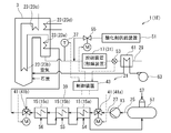
- FIG. 1 is a diagram showing a schematic configuration of a thermal power generation system 1A according to an embodiment of the present invention.
- FIG. 2 is a diagram schematically showing a part of the configuration of a thermal power generation system 1B according to another embodiment.
- FIG. 3 is a diagram schematically showing a part of the configuration of a thermal power generation system 1C according to another embodiment.
- FIG. 4 is a diagram schematically showing a part of the configuration of a thermal power generation system 1D according to another embodiment.
- FIG. 5 is a diagram schematically showing a part of the configuration of a thermal power generation system 1E according to another embodiment.
- the thermal power generation systems 1A to 1E are collectively referred to as a thermal power generation system 1.
- the thermal power generation system 1 includes a boiler 3, at least one steam turbine 5, a generator 7, a condenser 9, at least one low-pressure feed water heater 11, a high-pressure feed pump 13, and at least one It has a high-pressure feed water heater 15, a catalyst device 17, a mercury oxide removing device 19, and an exhaust gas temperature adjusting device 21.
- the boiler 3 can generate a high-temperature combustion gas (exhaust gas) by burning fuel such as coal using air.
- the boiler 3 has at least one internal heat exchanger 23, and the at least one internal heat exchanger 23 is interposed in a circulation path 25 through which water can circulate.
- At least one internal heat exchanger 23 can exchange heat between the exhaust gas and water, and can generate steam by exchanging heat between the exhaust gas and water generated by burning the fuel.
- at least one internal heat exchanger 23 includes an economizer (a economizer) 23a, an evaporator (evaporator tube) 23b, a superheater 23c, and a reheater 23d.
- the economizer (a economizer) 23a, the evaporator 23b, the superheater 23c, and the reheater 23d are inserted in the circulation path 25 in this order in the water flow direction (circulation direction).
- the at least one steam turbine 5 is inserted in the circulation path 25 and can output power using steam.
- the at least one steam turbine 5 includes a high-pressure turbine 5a, an intermediate-pressure turbine 5b, and a low-pressure turbine 5c.
- the high-pressure turbine 5a, the intermediate-pressure turbine 5b, and the low-pressure turbine 5c are inserted in the circulation path 25 in this order in the water flow direction (circulation direction).
- the high pressure turbine 5a is located downstream of the superheater 23c, and the reheater 23d is located between the high pressure turbine 5a and the intermediate pressure turbine 5b.
- the generator 7 is connected to at least one steam turbine 5 and can generate power using the power output from the steam turbine 5.
- the condenser 9 can condense the steam discharged from the at least one steam turbine 5.
- At least one low-pressure feed water heater 11 is inserted in a feed water path 27 that forms a part of the circulation path 25.
- the water supply path 27 extends between the condenser 9 and at least one internal heat exchanger 23 of the boiler 3, and is a path for supplying liquid phase water to the internal heat exchanger 23.
- the at least one low-pressure feed water heater 11 can heat the water condensed by the condenser 9 using the steam extracted from the steam turbine 5.
- the number of the low-pressure feed water heaters 11 is not particularly limited.
- the low-pressure feed water heater 11 includes a first low-pressure feed water heater 11a, a second low-pressure feed water heater 11b, and A third low-pressure feed water heater 11c is included.
- steam S1, S2, and S3 extracted from the low-pressure turbine 5c can be supplied to the first low-pressure feed water heater 11a, the second low-pressure feed water heater 11b, and the third low-pressure feed water heater 11c, respectively.
- the at least one low-pressure feed water heater 11 is a mixed feed water heater, in which water flowing through the feed water path 27 and steam supplied to heat the water are mixed.
- the high-pressure feed pump 13 is inserted in the feed path 27 of the circulation path 25, and is located downstream of the low-pressure feed water heater 11 in the water flow direction (circulation direction).
- the high-pressure feed water pump 13 can increase the pressure of the water heated by the low-pressure feed water heater 11 and send it out.
- the at least one high-pressure feed water heater 15 is inserted in the water feed path 27 of the circulation path 25 and is positioned between the high-pressure feed water pump 13 and at least one internal heat exchanger 23.
- the high-pressure feed water heater 15 can heat the water sent out by the high-pressure feed water pump 13 using the steam extracted from at least one steam turbine 5.
- the number of high-pressure feed water heaters 15 is not particularly limited.
- the high-pressure feed water heater 15 includes a first high-pressure feed water heater 15a, a second high-pressure feed water heater 15b, and A third high-pressure feed water heater 15c is included.
- steam S4, S5, and S6 extracted from the high-pressure turbine 5a can be supplied to the first high-pressure feed water heater 15a, the second high-pressure feed water heater 15b, and the third high-pressure feed water heater 15c, respectively.
- the at least one high-pressure feed water heater 15 is a surface-type feed water heater, and the water flowing through the feed water path 27 and the steam supplied to heat the water are not mixed.
- the catalyst device 17 is inserted into an exhaust gas exhaust path 29 extending from the boiler 3.
- the catalyst device 17 includes a denitration device (SCR (Selective Catalytic Reduction) catalyst device) 31.
- the exhaust path 29 is a path for discharging exhaust gas after heat exchange with at least one internal heat exchanger 23 of the boiler 3.
- the exhaust gas after heat exchange with at least one internal heat exchanger 23 contains nitrogen oxides and metallic mercury.
- the catalyst device 17 has at least one kind of catalyst. At least one type of catalyst can promote the reduction reaction of nitrogen oxides and the oxidation reaction of metallic mercury respectively contained in the exhaust gas. Although not shown, at least one catalyst is held on a support.
- the catalyst is not particularly limited as long as it can promote the reduction reaction of nitrogen oxides and the oxidation reaction of metallic mercury.
- V vanadium
- W tungsten
- Mo mobdenum
- Ni nickel
- Co cobalt
- Fe iron
- Cr chromium
- Mn manganese
- Cu copper
- Pt platinum
- Ru ruthenium
- a noble metal such as Rh (rhodium), Pd (palladium), Ir (iridium), or a mixture thereof can be used.
- titania, silica, zirconia and their composite oxides, or zeolite can be used as the carrier.
- a composition containing an oxide of Ti (titanium), Mo and / or W, V, and Bi (bismuth), and an atomic ratio of Ti: (Mo + W): V is 75 to A catalyst having 98.9: 1 to 15: 0.1 to 10 and an atomic ratio of B / (Mo + W) of 0.1 to 0.8 can be used.
- a catalyst having a ratio of 5: 2 to 10: 0.5 to 10 and an atomic ratio of P / (Mo + W + V) of 0.5 to 1.5 can be used.
- titanium oxide is the main component, and an oxide of at least one element selected from the group consisting of W, Mo and V is included as an active component, and the atomic ratio of phosphorus to the active component is 0.
- titanium oxide and phosphoric acid or ammonium phosphate of more than 1 and not more than 15% by weight with respect to titanium oxide were brought into contact with each other in the presence of water, and phosphate ions were adsorbed on the surface.
- a catalyst in which oxo acid or oxo acid salt of Mo and / or W and oxo acid salt or vanadyl salt of V are supported on titanium oxide in an amount of more than 0 to 8 atomic% or less can be used.
- TiO 2 is used as a support, V 2 O 5 and MoO 3 are supported as active components on the support, and W, Cu, Co, Ni, Zn (zinc), and these compounds are used. What carried
- supported at least 1 type of atom or compound chosen from the group which consists of can be used.
- the at least one mercury oxide removing device 19 is located downstream of the catalyst device 17 and inserted in the exhaust passage 29, and can remove mercury oxide generated by the oxidation reaction of metallic mercury from the exhaust gas.
- the mercury oxide removing device 19 includes a dust collecting device 33 and a wet desulfurization device 35.
- the dust collector 33 mercury oxide is removed from the exhaust gas together with the ash.
- the desulfurization device 35 mercury oxide is dissolved in the absorbing solution and removed from the exhaust gas.
- the exhaust path 29 extends to a chimney 36 disposed downstream of the desulfurization device 35, and the exhaust gas from which mercury has been removed is released from the chimney 36 into the atmosphere.
- the exhaust gas temperature adjusting device 21 can adjust the temperature of the exhaust gas in the catalyst device 17 by adjusting the heating of water by at least one high-pressure feed water heater 15.
- the exhaust gas temperature adjusting device 21 can adjust the temperature of the exhaust gas in the catalyst device 17 by adjusting the heating of the water by the at least one high-pressure feed water heater 15. Therefore, according to the said structure, the temperature of the exhaust gas in the catalyst apparatus 17 can be adjusted with a simple structure, and the metal mercury in exhaust gas can be removed efficiently.
- the exhaust gas temperature adjustment device 21 includes an exhaust gas temperature sensor 37, at least one bypass passage 39, at least one bypass valve 41, and a control device 43.
- the exhaust gas temperature sensor 37 can measure the temperature of the exhaust gas in the catalyst device 17.
- the exhaust gas temperature sensor 37 may be disposed upstream of the catalyst device 17 in the exhaust gas flow direction or may be disposed downstream as long as the exhaust gas temperature in the catalyst device 17 can be measured.
- the at least one bypass passage 39 is provided in parallel with the water supply passage 27 so that at least one of the at least one high-pressure feed water heater 15 can be bypassed.
- the at least one bypass valve 41 can adjust the flow rate of water in the at least one bypass passage 39.
- the control device 43 is configured by a computer, for example, and is configured to adjust the opening degree of at least one bypass valve 41 based on the measurement result of the exhaust gas temperature sensor 37.
- the control device 43 of the exhaust gas temperature adjustment device 21 can adjust the opening degree of at least one bypass valve 41 based on the measurement result of the exhaust gas temperature sensor 37. For this reason, the temperature of the exhaust gas in the catalyst device 17 can be accurately adjusted with a simple configuration, and the metallic mercury in the exhaust gas can be efficiently removed.
- the temperature of the water supplied to the internal heat exchanger 23 is lowered as the flow rate of the water flowing through the bypass passage 39 is increased, and the temperature of the exhaust gas in the catalyst device 17 can be lowered.
- the temperature of the water supplied to the internal heat exchanger 23 increases as the flow rate of the water flowing through the bypass passage 39 decreases, and the temperature of the exhaust gas in the catalyst device 17 can be increased.
- the bypass passage 39 is provided so as to bypass all of the plurality of high-pressure feed water heaters 15a, 15b, 15c.
- the at least one bypass valve 41 includes two three-way valves 41a and 41b arranged at an upstream branch point and a downstream branch point between the bypass passage 39 and the water supply passage 27. According to the above configuration, when the control device 43 switches the three-way valves 41a and 41b, all the water flowing through the water supply path 27 flows through all of the plurality of high-pressure feed water heaters 15a, 15b, and 15c. Alternatively, all can be bypassed to flow.
- the bypass passage 39 includes a first bypass passage 39a that can bypass the first high-pressure feed water heater 15a and a second bypass that can bypass the second high-pressure feed water heater 15b.
- the passage 39b and a third bypass passage 39c that can bypass the third high-pressure feed water heater 15c are included.
- the downstream side of the first bypass path 39a and the upstream side of the second bypass path 39b may overlap, and the downstream side of the second bypass path 39b and the upstream side of the third bypass path 39c may overlap.
- the at least one bypass valve 41 is provided at an upstream branch point and a downstream branch point between each of the first bypass passage 39a, the second bypass passage 39b, and the third bypass passage 39c and the water supply passage 27.
- Four three-way valves 41c, 41d, 41e, and 41f are included.
- the controller 43 switches the three-way valves 41c, 41d, 41e, and 41f, so that all the water flowing through the water supply path 27 passes through all of the plurality of high-pressure feed water heaters 15a, 15b, and 15c. It can be made to flow, to pass through only part, or to bypass all.
- the water flowing through the water supply path 27 is supplied to the internal heat exchanger 23 by allowing only a part of the plurality of high-pressure feed water heaters 15a, 15b, and 15c to flow. Fine adjustment of water temperature. As a result, the temperature of the exhaust gas in the catalyst device 17 can be adjusted more accurately, and metallic mercury in the exhaust gas can be efficiently removed.
- the exhaust gas temperature adjustment device 21 includes an exhaust gas temperature sensor 37, at least one extraction valve 45, and a control device 43.
- the exhaust gas temperature sensor 37 is the same as that described in the above embodiment.
- the at least one extraction valve 45 controls the flow rate of the steam extracted from the at least one steam turbine 5 in at least one extraction passage 47 extending between the at least one steam turbine 5 and the at least one high-pressure feed water heater 15. It can be adjusted.
- At least one extraction passage 47 has a high pressure with each of the first high-pressure feed water heater 15 a, the second high-pressure feed water heater 15 b, and the third high-pressure feed water heater 15 c.
- a first bleed passage 47a, a second bleed passage 47b, and a third bleed passage 47c extending between the turbine 5a are included.
- the at least one bleed valve 45 includes a first bleed valve 45a, a second bleed valve 45b, and a third bleed valve 45c inserted in the first bleed passage 47a, the second bleed passage 47b, and the third bleed passage 47c, respectively. Is included.
- the first bleed valve 45a, the second bleed valve 45b, and the third bleed valve 45c adjust the flow rates of the steams S4, S5, and S6 in the corresponding first bleed passage 47a, second bleed passage 47b, and third bleed passage 47c, respectively. Is possible.
- the control device 43 is configured by a computer, for example, and is configured to adjust the opening of at least one extraction valve 45 based on the measurement result of the exhaust gas temperature sensor 37. For example, the control device 43 adjusts at least one of the first bleed valve 45a, the second bleed valve 45b, and the third bleed valve 45c to thereby adjust the first high pressure feed water heater 15a and the second high pressure feed water heater. The flow rate of the steam supplied to at least one of 15b and the third high-pressure feed water heater 15c can be adjusted.
- the exhaust gas temperature adjustment device 21 adjusts the opening degree of the extraction valve 45 based on the measurement result of the exhaust gas temperature sensor 37, so that the temperature of the exhaust gas in the catalyst device 17 can be adjusted with a simple configuration.
- the metal mercury in the exhaust gas can be efficiently removed by adjusting precisely.
- the control device 43 may be configured to adjust the opening degrees of both the at least one bypass valve 41 and the at least one extraction valve 45 based on the measurement result of the exhaust gas temperature sensor 37. You may be comprised so that the opening degree of either one may be adjusted.
- the control device 43 is configured to adjust only the opening degree of the extraction valve 45, the bypass passage 39 and the bypass valve 41 can be omitted.
- the fuel supplied to the boiler 3 is lignite
- the exhaust gas temperature adjusting device 21 adjusts the temperature of the exhaust gas in the catalyst device 17 to 420 ° C. or lower, preferably 400 ° C. or lower. It is configured.
- the exhaust gas temperature adjusting device 21 is configured to adjust the temperature of the exhaust gas in the catalyst device 17 to 420 ° C. or less. The chemical equilibrium between them can be maintained in a state where metal mercury is relatively low, and mercury can be reliably and efficiently removed from the exhaust gas.
- the exhaust gas temperature adjustment device 21 is configured to adjust the temperature of the exhaust gas in the catalyst device 17 to 400 ° C. or less. According to the above configuration, the exhaust gas temperature adjusting device 21 adjusts the temperature of the exhaust gas in the catalyst device 17 to 400 ° C. or less, so that the chemical equilibrium between the metal mercury and the mercury oxide is relatively increased. It can be maintained in a small state, and mercury can be reliably and efficiently removed from the exhaust gas.
- the exhaust gas temperature adjusting device 21 is configured to adjust the temperature of the exhaust gas in the catalyst device 17 to 290 ° C. or higher, preferably 320 ° C. or higher.
- the reduction reaction of nitrogen oxide proceeds smoothly when the temperature of the exhaust gas in the catalyst device 17 is 290 ° C. or higher, preferably 320 ° C. or higher.
- the temperature of the exhaust gas is less than 320 ° C., depending on the concentration of SOx in the exhaust gas and the NH 3 concentration injected to obtain the required denitration performance, acidic ammonium sulfate may be deposited on the catalyst and the activity of the catalyst may be reduced. is there. When the activity of the catalyst is lowered, the oxidation reaction of mercury may not proceed smoothly.
- the exhaust gas temperature adjusting device 21 is configured to adjust the temperature of the exhaust gas in the catalyst device 17 to 290 ° C. or more, preferably 320 ° C. or more. Nitrogen oxides in the exhaust gas are reliably and efficiently removed, and mercury in the exhaust gas is also reliably and efficiently removed.
- the exhaust gas temperature adjustment device 21 is configured to adjust the temperature of the exhaust gas in the catalyst device 17 to 290 ° C. or more and 420 ° C. or less. In some embodiments, the exhaust gas temperature adjustment device 21 is configured to adjust the temperature of the exhaust gas in the catalyst device 17 to 320 ° C. or more and 420 ° C. or less. In some embodiments, the exhaust gas temperature adjusting device 21 is configured to adjust the temperature of the exhaust gas in the catalyst device 17 to 320 ° C. or more and 400 ° C. or less. According to this configuration, by adjusting the temperature of the exhaust gas to 400 ° C.
- the exhaust gas temperature adjustment device 21 is configured to adjust the temperature of the exhaust gas in the catalyst device 17 to 350 ° C. or more and 400 ° C. or less. According to this configuration, by adjusting the temperature of the exhaust gas to 350 ° C. or higher, precipitation of acidic ammonium sulfate is more reliably suppressed, and nitrogen oxides in the exhaust gas are reliably and efficiently removed, and in the exhaust gas Of mercury is also reliably and efficiently removed.
- the exhaust gas temperature adjustment device 21 adjusts the temperature of the exhaust gas in the catalyst device 17 to 290 ° C. or more and 420 ° C. or less when the load factor of the boiler 3 is 50% or more and 100% or less. It is configured. When the load factor of the boiler 3 is 50% or more and 100% or less, the temperature of the exhaust gas in the catalyst device 17 tends to be high. In this regard, according to the above configuration, even if the load factor of the boiler 3 is 50% or more and 100% or less, the temperature of the exhaust gas in the catalyst device 17 can be adjusted to 290 ° C. or more and 420 ° C. or less. In some embodiments, the exhaust gas temperature adjustment device 21 adjusts the temperature of the exhaust gas in the catalyst device 17 to 320 ° C.
- the exhaust gas temperature adjustment device 21 adjusts the temperature of the exhaust gas in the catalyst device 17 to 350 ° C. or more and 400 ° C. or less when the load factor of the boiler 3 is 50% or more and 100% or less. It is configured.
- the exhaust gas temperature adjustment device 21 adjusts the temperature of the exhaust gas in the catalyst device 17 to 290 ° C. or more and 420 ° C. or less when the load factor of the boiler 3 is 25% or more and 50% or less. It is configured. When the load factor of the boiler 3 is 25% or more and 50% or less, the temperature of the exhaust gas in the catalyst device 17 tends to be low. In this regard, according to the above configuration, even if the load factor of the boiler 3 is 25% or more and 50% or less, the temperature of the exhaust gas in the catalyst device 17 can be adjusted to 290 ° C. or more and 420 ° C. or less. In some embodiments, the exhaust gas temperature adjustment device 21 adjusts the temperature of the exhaust gas in the catalyst device 17 to 320 ° C.
- the exhaust gas temperature adjustment device 21 adjusts the temperature of the exhaust gas in the catalyst device 17 to 350 ° C. or more and 400 ° C. or less when the load factor of the boiler 3 is 25% or more and 100% or less. It is configured.
- the exhaust gas temperature adjusting device 21 is configured such that water is heated by all the high-pressure feed water heaters 15 when the boiler 3 is started. According to the said structure, the temperature of the water supplied to the internal heat exchanger 23 can be raised rapidly by heating water with all the high voltage
- the exhaust gas temperature adjusting device 21 is water (feed water) supplied from at least one high-pressure feed water heater 15 to at least one internal heat exchanger 23. It further has a feed water temperature sensor 49 capable of measuring the temperature. Then, the control device 43 at least 1 based on the temperature of the exhaust gas in the catalyst device 17 measured by the exhaust gas temperature sensor 37 and the temperature of the feed water to the internal heat exchanger 23 measured by the feed water temperature sensor 49. The temperature of the exhaust gas in the catalyst device 17 can be adjusted by adjusting the heating of water by the two high-pressure feed water heaters 15.
- the exhaust gas temperature adjusting device 21 is based on the temperature of the feed water to the internal heat exchanger 23 measured by the feed water temperature sensor 49 in addition to the temperature of the exhaust gas in the catalyst device 17.
- the feed water temperature sensor 49 is disposed in a portion of the feed water path 27 that extends between the boiler 3 and the high-pressure feed water heater 15.
- the exhaust gas temperature adjusting device 21 is configured to adjust the feed water temperature to the internal heat exchanger 23 to 130 ° C. or more and 300 ° C. or less.
- the exhaust gas temperature adjusting device 21 controls the exhaust gas in the catalyst device 17 when the load factor of the boiler 3 is 25% or more and 50% or less and when the load factor is 50% or more and 100% or less. The temperature is adjusted to 290 ° C. or higher and 420 ° C. or lower, and the feed water temperature to the internal heat exchanger 23 is adjusted to 130 ° C. or higher and 300 ° C. or lower. In some embodiments, the exhaust gas temperature adjusting device 21 controls the exhaust gas in the catalyst device 17 when the load factor of the boiler 3 is 25% or more and 50% or less and when the load factor is 50% or more and 100% or less. The temperature is adjusted to 320 ° C. or more and 400 ° C.
- the feed water temperature to the internal heat exchanger 23 is adjusted to 130 ° C. or more and 300 ° C. or less.
- the exhaust gas temperature adjusting device 21 controls the exhaust gas in the catalyst device 17 when the load factor of the boiler 3 is 25% or more and 50% or less and when the load factor is 50% or more and 100% or less. The temperature is adjusted to 350 ° C. or higher and 400 ° C. or lower, and the feed water temperature to the internal heat exchanger 23 is adjusted to 130 ° C. or higher and 300 ° C. or lower.
- the thermal power generation systems 1 ⁇ / b> A and 1 ⁇ / b> E further include an oxidant supply device 51.
- the oxidant supply device 51 can supply the catalyst device 17 with halogen to be used for the oxidation reaction of metallic mercury. According to the above configuration, even when the concentration of hydrogen chloride in the exhaust gas is low, by supplying halogen to the catalyst device 17 by the oxidizer supply device 51, metal mercury can be reacted with halogen to generate mercury oxide. In addition, mercury can be reliably and efficiently removed from the exhaust gas.
- the oxidant supply device 51 is configured to be able to supply an aqueous solution of ammonium halide, for example, ammonium chloride, as an oxidant upstream of the catalyst device 17.
- ammonium halide for example, ammonium chloride
- ammonium bromide or ammonium iodide can be used as the ammonium halide.
- the thermal power generation system 1 ⁇ / b> E further includes a mercury concentration sensor 53 and an oxidant supply amount adjustment valve 55.
- the mercury concentration sensor 53 is provided in the exhaust passage 29 so as to be located downstream of the catalyst device 17 and can measure the mercury concentration in the exhaust gas.
- the oxidant supply amount adjustment valve 55 is provided in the oxidant supply path to the catalyst device 17 and can adjust the flow rate of the oxidant supplied to the catalyst device 17.
- the control device 43 may be used. The control device may be prepared.
- the mercury concentration is measured, and the supply amount of the oxidant is adjusted based on the measurement results of the metallic mercury concentration and the mercury oxide concentration, so that the metallic mercury is reliably reacted with the halogen so that the mercury oxide is It can be produced and mercury can be reliably and efficiently removed from the exhaust gas.
- FIG. 6 is a flowchart showing a schematic procedure of the above-described thermal power generation system 1 control method according to an embodiment of the present invention.
- the control method of the thermal power generation system 1 has an exhaust gas temperature adjustment step S10.
- the temperature of the exhaust gas in the catalyst device 17 is adjusted by adjusting the heating of water by at least one high-pressure feed water heater 15.
- the temperature of the exhaust gas in the catalyst device 17 can be adjusted by adjusting the heating of the water by the high-pressure feed water heater 15 in the exhaust gas temperature adjustment step S10. Therefore, according to the said structure, the temperature of the exhaust gas in the catalyst apparatus 17 can be adjusted with a simple structure, and the metal mercury in exhaust gas can be removed efficiently.
- the heating of the water by the high-pressure feed water heater 15 is adjusted so that the temperature of the exhaust gas in the catalyst device 17 is 290 ° C. or higher and 420 ° C. or lower. In some embodiments, in the exhaust gas temperature adjustment step S10, the heating of the water by the high-pressure feed water heater 15 is adjusted so that the temperature of the exhaust gas in the catalyst device 17 is not less than 320 ° C and not more than 400 ° C. In some embodiments, in the exhaust gas temperature adjustment step S10, the heating of the water by the high-pressure feed water heater 15 is adjusted so that the temperature of the exhaust gas in the catalyst device 17 is 350 ° C. or higher and 400 ° C. or lower.
- the present invention is not limited to the above-described embodiments, and includes forms obtained by changing the above-described embodiments and forms obtained by combining these forms.
- a bypass duct that connects the upstream and downstream flues of the economizer (a economizer) 23a is provided so that the boiler 3 is started up or when the load factor of the boiler 3 is 50% or less (low load).
- the exhaust gas temperature itself is low, a part of the exhaust gas at the entrance of the economizer 23a is bypassed by the economizer 23a by the bypass duct, and the exit of the economizer 23a is saved.
- the operation of controlling the exhaust gas temperature in the catalyst device 17 to the above-described temperature range can also be combined by combining the flow into the catalyst device 17.
- the thermal power generation system 1 may further include a deaerator 57 for removing a gas contained in water.
- the deaerator 57 is located between the low-pressure feed water heater 11 and the high-pressure feed water pump 13 and is inserted into the feed water path 27. Then, a part of the steam (steam S7) discharged from the intermediate pressure turbine 5b may be supplied to the deaerator 57.
- the thermal power generation system 1 may further include a condensate pump 59 that sends the water condensed in the condenser 9 toward the low-pressure feed water heater 11.
- the condensate pump 59 is located between the low pressure feed water heater 11 and the high pressure feed water pump 13 and is inserted in the feed water path 27.
- the thermal power generation system 1 may have an air heater 61 for heating the air supplied to the boiler 3.
- the air heater 61 is located between the catalyst device 17 and the mercury oxide removing device 19 and is inserted in the exhaust passage 29, and can heat the air supplied to the boiler 3 by the blower 63 by heat exchange with the exhaust gas. is there.
- the thermal power generation system 1 is a coal thermal power generation system that burns coal as fuel, but the fuel is not limited to coal, and may be heavy oil or the like.
Landscapes
- Engineering & Computer Science (AREA)
- Chemical & Material Sciences (AREA)
- Mechanical Engineering (AREA)
- General Engineering & Computer Science (AREA)
- Combustion & Propulsion (AREA)
- Environmental & Geological Engineering (AREA)
- General Chemical & Material Sciences (AREA)
- Analytical Chemistry (AREA)
- Biomedical Technology (AREA)
- Oil, Petroleum & Natural Gas (AREA)
- Chemical Kinetics & Catalysis (AREA)
- Physics & Mathematics (AREA)
- Thermal Sciences (AREA)
- Health & Medical Sciences (AREA)
- Chimneys And Flues (AREA)
- Exhaust Gas Treatment By Means Of Catalyst (AREA)
- Treating Waste Gases (AREA)
- Catalysts (AREA)
Abstract
Description
例えば、特許文献1が開示する排ガス処理装置によれば、脱硝触媒の上流に設けられた冷却器によって排ガスの温度が所定の温度、300℃~400℃に制御される。そして、冷却器によって所定の温度に制御された排ガスを脱硝触媒に導入し、排ガス中の窒素酸化物を還元して除去する一方、排ガス中の金属水銀を塩化水素と反応させて塩化水銀を生成させる。排ガス中に含まれる塩化水銀は、脱硝触媒の下流に設けられた脱硫装置にて吸収液に溶解して排ガス中から除去される。かくして、特許文献1が開示する排ガス処理装置によれば、排ガス中の水銀の除去効率を向上させることができる。
水が循環可能な循環路に介挿された少なくとも1つの内部熱交換器であって、燃料を燃焼させて発生した排ガスと前記水との間で熱交換を行うことにより蒸気を生成可能な少なくとも1つの内部熱交換器を有するボイラと、
前記循環路に介挿され、前記蒸気を利用して動力を出力可能な少なくとも1つの蒸気タービンと、
前記蒸気タービンが出力した動力を利用して発電可能な発電機と、
前記蒸気タービンから排出された前記蒸気を凝縮可能な復水器と、
前記復水器から前記少なくとも1つの内部熱交換器まで延びる前記循環路の一部をなす給水経路に介挿され、前記少なくとも1つの蒸気タービンから抽気された蒸気を利用して、前記復水器によって凝縮された前記水を加熱可能な少なくとも1つの低圧給水加熱器と、
前記少なくとも1つの低圧給水加熱器の下流に位置して前記循環路の給水経路に介挿され、前記少なくとも1つの低圧給水加熱器によって加熱された前記水の圧力を上昇させて送出可能な高圧給水ポンプと、
前記高圧給水ポンプと前記少なくとも1つの内部熱交換器との間に位置して前記循環路の給水経路に介挿され、前記少なくとも1つの蒸気タービンから抽気された蒸気を利用して、前記高圧給水ポンプによって送出された前記水を加熱可能な少なくとも1つの高圧給水加熱器と、
前記ボイラから延びる前記排ガスの排気経路に介挿され、前記排ガスにそれぞれ含まれる窒素酸化物の還元反応及び金属水銀の酸化反応を促進可能な少なくとも一種の触媒を有する触媒装置と、
前記触媒装置の下流に位置して前記排気経路に介挿され、前記金属水銀の酸化反応により生成された酸化水銀を前記排ガスから除去可能な少なくとも1つの酸化水銀除去装置と、
前記少なくとも1つの高圧給水加熱器による前記水の加熱を調整することにより、前記触媒装置における前記排ガスの温度を調整可能な排ガス温度調整装置と
を備える。
前記排ガス温度調整装置は、
前記触媒装置における前記排ガスの温度を測定可能な排ガス温度センサと、
前記少なくとも1つの高圧給水加熱器のうち少なくとも1つをバイパス可能なように前記給水経路と並列に設けられた少なくとも1つのバイパス路と、
前記少なくとも1つのバイパス路における前記水の流量を調整可能な少なくとも1つのバイパス弁と、
前記排ガス温度センサの測定結果に基づいて、前記少なくとも1つのバイパス弁の開度を調整するように構成された制御装置と
を含む。
前記排ガス温度調整装置は、
前記触媒装置における前記排ガスの温度を測定可能な排ガス温度センサと、
前記少なくとも1つの蒸気タービンと前記少なくとも1つの高圧給水加熱器との間を延びる少なくとも1つの抽気路における、前記少なくとも1つの蒸気タービンから抽気された蒸気の流量を調整可能な少なくとも1つの抽気弁と、
前記排ガス温度センサの測定結果に基づいて、前記少なくとも1つの抽気弁の開度を調整するように構成された制御装置と
を含む。
前記燃料は褐炭であり、
前記排ガス温度調整装置は、前記触媒装置における前記排ガスの温度を420℃以下、好ましくは400℃以下に調整するように構成されている。
この点、上記構成(4)によれば、排ガス温度調整装置は、触媒装置における排ガスの温度を420℃以下に調整するように構成されているので、金属水銀と酸化水銀の間での化学平衡を、相対的に金属水銀が少ない状態に維持することができ、排ガス中から水銀を確実且つ効率的に除去可能である。
前記排ガス温度調整装置は、前記触媒装置における前記排ガスの温度を290℃好ましくは320℃以上に調整するように構成されている。
この点、上記構成(5)によれば、排ガス温度調整装置は、触媒装置での排ガスの温度を290℃以上好ましくは320℃以上に調整するように構成されているので、排ガス中の窒素酸化物が確実かつ効率的に除去されるとともに、排ガス中の水銀も確実且つ効率的に除去される。
前記金属水銀の酸化反応に供されるハロゲンを前記触媒装置に供給可能な酸化剤供給装置を備える。
水が循環可能な循環路に介挿された少なくとも1つの内部熱交換器であって、燃料を燃焼させて発生した排ガスと前記水との間で熱交換を行うことにより蒸気を生成可能な少なくとも1つの内部熱交換器を有するボイラと、
前記循環路に介挿され、前記蒸気を利用して動力を出力可能な少なくとも1つの蒸気タービンと、
前記蒸気タービンが出力した動力を利用して発電可能な発電機と、
前記蒸気タービンから排出された前記蒸気を凝縮可能な復水器と、
前記復水器から前記少なくとも1つの内部熱交換器まで延びる前記循環路の一部をなす給水経路に介挿され、前記少なくとも1つの蒸気タービンから抽気された蒸気を利用して、前記復水器によって凝縮された前記水を加熱可能な少なくとも1つの低圧給水加熱器と、
前記少なくとも1つの低圧給水加熱器の下流に位置して前記循環路の給水経路に介挿され、前記少なくとも1つの低圧給水加熱器によって加熱された前記水の圧力を上昇させて送出可能な高圧給水ポンプと、
前記高圧給水ポンプと前記少なくとも1つの内部熱交換器との間に位置して前記循環路の給水経路に介挿され、前記少なくとも1つの蒸気タービンから抽気された蒸気を利用して、前記高圧給水ポンプによって送出された前記水を加熱可能な少なくとも1つの高圧給水加熱器と、
前記ボイラから延びる前記排ガスの排気経路に介挿され、前記排ガスにそれぞれ含まれる窒素酸化物の還元反応及び金属水銀の酸化反応を促進可能な少なくとも一種の触媒を有する触媒装置と、
前記触媒装置の下流に位置して前記排気経路に介挿され、前記金属水銀の酸化反応により生成された酸化水銀を前記排ガスから除去可能な少なくとも1つの酸化水銀除去装置と、
を備える火力発電システムの制御方法において、
前記少なくとも1つの高圧給水加熱器による前記水の加熱を調整することにより、前記触媒装置における前記排ガスの温度を調整する工程を備える。
例えば、「ある方向に」、「ある方向に沿って」、「平行」、「直交」、「中心」、「同心」或いは「同軸」等の相対的或いは絶対的な配置を表す表現は、厳密にそのような配置を表すのみならず、公差、若しくは、同じ機能が得られる程度の角度や距離をもって相対的に変位している状態も表すものとする。
例えば、「同一」、「等しい」及び「均質」等の物事が等しい状態であることを表す表現は、厳密に等しい状態を表すのみならず、公差、若しくは、同じ機能が得られる程度の差が存在している状態も表すものとする。
例えば、四角形状や円筒形状等の形状を表す表現は、幾何学的に厳密な意味での四角形状や円筒形状等の形状を表すのみならず、同じ効果が得られる範囲で、凹突起や面取り部等を含む形状も表すものとする。
一方、一の構成要素を「備える」、「具える」、「具備する」、「含む」、又は、「有する」という表現は、他の構成要素の存在を除外する排他的な表現ではない。
なお、以下の説明では、火力発電システム1A~1Eを一括して火力発電システム1とも称する。
復水器9は、少なくとも1つの蒸気タービン5から排出された蒸気を凝縮可能である。
少なくとも1つの低圧給水加熱器11は、蒸気タービン5から抽気された蒸気を利用して、復水器9によって凝縮された水を加熱可能である。低圧給水加熱器11の数は特に限定されることはないが、例えば、図1に示したように、低圧給水加熱器11は、第1低圧給水加熱器11a、第2低圧給水加熱器11b及び第3低圧給水加熱器11cを含む。第1低圧給水加熱器11a、第2低圧給水加熱器11b及び第3低圧給水加熱器11cには、例えば、低圧タービン5cから抽気された蒸気S1,S2,S3をそれぞれ供給可能である。例えば、少なくとも1つの低圧給水加熱器11は、混合形給水加熱器であり、給水経路27を流れる水と、水を加熱するために供給された蒸気とが混合される。
排気経路29は、ボイラ3の少なくとも1つの内部熱交換器23と熱交換した後の排ガスを排出するための経路である。少なくとも1つの内部熱交換器23と熱交換した後の排ガスは、窒素酸化物及び金属水銀を含んでいる。
触媒装置17は、少なくとも一種の触媒を有している。少なくとも一種の触媒は、排ガスにそれぞれ含まれる窒素酸化物の還元反応及び金属水銀の酸化反応を促進可能である。
図示しないけれども、少なくとも一種の触媒は、担体に保持されている。
更に、例えば、触媒として、Ti、Mo及び/又はW、V、並びに、P(リン)の各酸化物を含む組成物であって、Ti:(Mo+W):Vの原子比が85~97.5:2~10:0.5~10であり、且つ、P/(Mo+W+V)の原子比が0.5~1.5である触媒を用いることができる。
更に、例えば、触媒として、TiO2を担体とし、担体上にV2O5及びMoO3を活性成分として担持し、W、Cu、Co、Ni、及びZn(亜鉛)、並びに、これらの化合物からなる群より選ばれる少なくとも一種の原子又は化合物を担持したものを用いることができる。
排ガス温度センサ37は、触媒装置17における排ガスの温度を測定可能である。なお、排ガス温度センサ37は、触媒装置17における排ガスの温度を測定可能であれば、排ガスの流れ方向にて触媒装置17の上流に配置されてもよく、又は、下流に配置されてもよい。
少なくとも1つのバイパス弁41は、少なくとも1つのバイパス路39における水の流量を調整可能である。
制御装置43は、例えばコンピュータによって構成されており、排ガス温度センサ37の測定結果に基づいて、少なくとも1つのバイパス弁41の開度を調整するように構成されている。
なお、バイパス路39を流れる水の流量を増やすほど、内部熱交換器23に供給される水の温度が低下し、触媒装置17での排ガスの温度を低下させることができる。一方、バイパス路39を流れる水の流量を減らすほど、内部熱交換器23に供給される水の温度が上昇し、触媒装置17での排ガスの温度を上昇させることができる。
上記構成によれば、制御装置43が三方弁41a,41bを切り替えることにより、給水経路27を流れる全ての水が、複数の高圧給水加熱器15a,15b,15cの全てを通過して流れるか、あるいは、全てをバイパスして流れるようにすることができる。
そして、少なくとも1つのバイパス弁41は、第1バイパス路39a、第2バイパス路39b及び第3バイパス路39cの各々と給水経路27との上流側の分岐点及び下流側の分岐点に設けられた4つの三方弁41c,41d,41e,41fを含んでいる。
排ガス温度センサ37は、上述した実施形態で説明したものと同じものである。
少なくとも1つの抽気弁45は、少なくとも1つの蒸気タービン5と少なくとも1つの高圧給水加熱器15との間を延びる少なくとも1つの抽気路47における、少なくとも1つの蒸気タービン5から抽気された蒸気の流量を調整可能である。
そして、少なくとも1つの抽気弁45は、第1抽気路47a、第2抽気路47b及び第3抽気路47cにそれぞれ介挿された第1抽気弁45a、第2抽気弁45b及び第3抽気弁45cを含んでいる。第1抽気弁45a、第2抽気弁45b及び第3抽気弁45cは、それぞれ対応する第1抽気路47a、第2抽気路47b及び第3抽気路47cにおける蒸気S4,S5,S6の流量を調整可能である。
なお、制御装置43は、排ガス温度センサ37の測定結果に基づいて、少なくとも1つのバイパス弁41及び少なくとも1つの抽気弁45の両方の開度を調整するように構成されていてもよいし、いずれか一方の開度を調整するように構成されていてもよい。制御装置43が抽気弁45の開度のみを調整するように構成されている場合、バイパス路39及びバイパス弁41は省略可能である。
上記構成によれば、排ガス温度調整装置21が、触媒装置17における排ガスの温度を400℃以下に調整することで、金属水銀と酸化水銀の間での化学平衡を、相対的に金属水銀がより少ない状態に維持することができ、排ガス中から水銀を確実且つ効率的に除去可能である。
窒素酸化物の還元反応は、触媒装置17での排ガスの温度が290℃以上好ましくは320℃以上であると円滑に進行する。一方、排ガスの温度が320℃未満では、排ガス中のSOx濃度及び必要な脱硝性能を得る為に注入されるNH3濃度によるが酸性硫安が触媒上に析出し、触媒の活性が低下する虞がある。触媒の活性が低下すると、水銀の酸化反応が円滑に進行しなくなる虞がある。
幾つかの実施形態では、排ガス温度調整装置21は、触媒装置17での排ガスの温度を320℃以上420℃以下に調整するように構成されている。
幾つかの実施形態では、排ガス温度調整装置21は、触媒装置17での排ガスの温度を320℃以上400℃以下に調整するように構成されている。
この構成によれば、排ガスの温度を400℃以下に調整することで、金属水銀と酸化水銀の間での化学平衡を、相対的に金属水銀がより一層少ない状態に維持することができ、排ガス中から水銀をより一層確実且つ効率的に除去可能である。
幾つかの実施形態では、排ガス温度調整装置21は、触媒装置17での排ガスの温度を350℃以上400℃以下に調整するように構成されている。
この構成によれば、排ガスの温度を350℃以上に調整することで、酸性硫安の析出がより一層確実に抑制され、排ガス中の窒素酸化物が確実かつ効率的に除去されるとともに、排ガス中の水銀も確実且つ効率的に除去される。
ボイラ3の負荷率が50%以上100%以下である場合、触媒装置17での排ガスの温度が高くなりやすい。この点、上記構成によれば、ボイラ3の負荷率が50%以上100%以下であっても、触媒装置17での排ガスの温度を290℃以上420℃以下に調整可能である。
幾つかの実施形態では、排ガス温度調整装置21は、ボイラ3の負荷率が50%以上100%以下である場合に、触媒装置17での排ガスの温度を320℃以上400℃以下に調整するように構成されている。
幾つかの実施形態では、排ガス温度調整装置21は、ボイラ3の負荷率が50%以上100%以下である場合に、触媒装置17での排ガスの温度を350℃以上400℃以下に調整するように構成されている。
ボイラ3の負荷率が25%以上50%以下である場合、触媒装置17での排ガスの温度が低くなりやすい。この点、上記構成によれば、ボイラ3の負荷率が25%以上50%以下であっても、触媒装置17での排ガスの温度を290℃以上420℃以下に調整可能である。
幾つかの実施形態では、排ガス温度調整装置21は、ボイラ3の負荷率が25%以上100%以下である場合に、触媒装置17での排ガスの温度を320℃以上400℃以下に調整するように構成されている。
幾つかの実施形態では、排ガス温度調整装置21は、ボイラ3の負荷率が25%以上100%以下である場合に、触媒装置17での排ガスの温度を350℃以上400℃以下に調整するように構成されている。
上記構成によれば、ボイラ3の起動時、全ての高圧給水加熱器15によって水を加熱することで、内部熱交換器23に供給される水の温度を速やかに上昇させることができ、触媒装置17での排ガスの温度を速やかに上昇させることができる。
なお、給水温度センサ49は、ボイラ3と高圧給水加熱器15との間を延びる給水経路27の部分に配置される。
幾つかの実施形態では、排ガス温度調整装置21は、ボイラ3の負荷率が25%以上50%以下である場合、及び、50%以上100%以下である場合に、触媒装置17での排ガスの温度を320℃以上400℃以下に調整し、且つ、内部熱交換器23への給水温度を130℃以上300℃以下に調整するように構成されている。
幾つかの実施形態では、排ガス温度調整装置21は、ボイラ3の負荷率が25%以上50%以下である場合、及び、50%以上100%以下である場合に、触媒装置17での排ガスの温度を350℃以上400℃以下に調整し、且つ、内部熱交換器23への給水温度を130℃以上300℃以下に調整するように構成されている。
上記構成によれば、排ガス中の塩化水素濃度が低い場合でも、酸化剤供給装置51によって触媒装置17にハロゲンを供給することによって、金属水銀をハロゲンと反応させて酸化水銀を生成することができ、排ガス中から水銀を確実且つ効率的に除去可能である。
上記構成によれば、窒素酸化物の還元反応に供されるアンモニウムも触媒装置17に同時に供給することができる。
なお、ハロゲン化アンモニウムとして、塩化アンモニウムの外に、臭化アンモニウムやヨウ化アンモニウムを用いることができる。
水銀濃度センサ53は、例えば、触媒装置17よりも下流に位置して排気経路29に設けられ、排ガス中の水銀濃度を測定可能である。酸化剤供給量調整弁55は、触媒装置17への酸化剤の供給路に設けられ、触媒装置17に供給される酸化剤の流量を調整可能である。そして、水銀濃度センサ53の金属水銀濃度と酸化水銀濃度の測定結果に基づいて、触媒装置17に供給される酸化剤の流量を調整可能とするために、制御装置43を用いてもよく、別の制御装置を用意してもよい。
上記した構成によれば、水銀濃度を測定し、金属水銀濃度と酸化水銀濃度の測定結果に基づいて酸化剤の供給量を調整することで、金属水銀をハロゲンと確実に反応させて酸化水銀を生成することができ、排ガス中から水銀を確実且つ効率的に除去可能である。
図6に示したように、火力発電システム1の制御方法は、排ガス温度調整工程S10を有している。排ガス温度調整工程S10では、少なくとも1つの高圧給水加熱器15による水の加熱を調整することにより、触媒装置17における排ガスの温度を調整する。
上記構成を有する火力発電システム1の制御方法によれば、排ガス温度調整工程S10において、高圧給水加熱器15による水の加熱を調整することにより、触媒装置17における排ガスの温度を調整可能である。従って、上記構成によれば、簡単な構成にて、触媒装置17における排ガスの温度を調整し、排ガス中の金属水銀を効率的に除去可能である。
幾つかの実施形態では、排ガス温度調整工程S10にて、触媒装置17での排ガスの温度が320℃以上400℃以下になるように、高圧給水加熱器15による水の加熱が調整される。
幾つかの実施形態では、排ガス温度調整工程S10にて、触媒装置17での排ガスの温度が350℃以上400℃以下になるように、高圧給水加熱器15による水の加熱が調整される。
例えば、エコノマイザ(節炭器)23aの上流と下流の煙道を互いに連通するバイパスダクトを設け、ボイラ3の起動時や、ボイラ3の負荷率が50%以下の部分負荷時(低負荷時)に、排ガス温度自体が低いときは、エコノマイザ(節炭器)23a入口の排ガスの一部を、前記バイパスダクトにより、エコノマイザ(節炭器)23aをバイパスし、エコノマイザ(節炭器)23aの出口で合流させて、触媒装置17へと流すことにより、触媒装置17における排ガス温度を前述した温度範囲に制御する運用を組み合わせることもできる。
また例えば、火力発電システム1は、復水器9で凝縮させられた水を低圧給水加熱器11に向けて送出する復水ポンプ59を更に有していてもよい。この場合、復水ポンプ59は、低圧給水加熱器11と高圧給水ポンプ13との間に位置して、給水経路27に介挿される。
更に例えば、火力発電システム1は、ボイラ3に供給される空気を加熱するための空気加熱器61を有していてもよい。空気加熱器61は、触媒装置17と酸化水銀除去装置19との間に位置して排気経路29に介挿され、送風機63によってボイラ3に供給される空気を排ガスとの熱交換によって加熱可能である。
また例えば、上述した実施形態では、火力発電システム1は、燃料として石炭を燃焼させる石炭火力発電システムであったが、燃料は石炭に限定されることはなく、重油等であってもよい。
3 ボイラ
5 蒸気タービン
5a 高圧タービン
5b 中圧タービン
5c 低圧タービン
7 発電機
9 復水器
11 低圧給水加熱器
11a 第1低圧給水加熱器
11b 第2低圧給水加熱器
11c 第3低圧給水加熱器
13 高圧給水ポンプ
15 高圧給水加熱器
15a 第1高圧給水加熱器
15b 第2高圧給水加熱器
15c 第3高圧給水加熱器
17 触媒装置
19 酸化水銀除去装置
21 排ガス温度調整装置
23 内部熱交換器
23a エコノマイザ
23b 蒸発器
23c 過熱器
23d 再熱器
25 循環路
27 給水経路
29 排気経路
31 脱硝装置
33 集塵装置
35 脱硫装置
36 煙突
37 排ガス温度センサ
39 バイパス路
39a 第1バイパス路
39b 第2バイパス路
39c 第3バイパス路
41 バイパス弁
41a,41b,41c,41d,41e,41f 三方弁
43 制御装置
45 抽気弁
45a 第1抽気弁
45b 第2抽気弁
45c 第3抽気弁
47 抽気路
47a 第1抽気路
47b 第2抽気路
47c 第3抽気路
49 給水温度センサ
51 酸化剤供給装置
53 水銀濃度センサ
55 酸化剤供給量調整弁
57 脱気器
59 復水ポンプ
61 空気加熱器
63 送風機
Claims (7)
- 水が循環可能な循環路に介挿された少なくとも1つの内部熱交換器であって、燃料を燃焼させて発生した排ガスと前記水との間で熱交換を行うことにより蒸気を生成可能な少なくとも1つの内部熱交換器を有するボイラと、
前記循環路に介挿され、前記蒸気を利用して動力を出力可能な少なくとも1つの蒸気タービンと、
前記蒸気タービンが出力した動力を利用して発電可能な発電機と、
前記蒸気タービンから排出された前記蒸気を凝縮可能な復水器と、
前記復水器から前記少なくとも1つの内部熱交換器まで延びる前記循環路の一部をなす給水経路に介挿され、前記少なくとも1つの蒸気タービンから抽気された蒸気を利用して、前記復水器によって凝縮された前記水を加熱可能な少なくとも1つの低圧給水加熱器と、
前記少なくとも1つの低圧給水加熱器の下流に位置して前記循環路の給水経路に介挿され、前記少なくとも1つの低圧給水加熱器によって加熱された前記水の圧力を上昇させて送出可能な高圧給水ポンプと、
前記高圧給水ポンプと前記少なくとも1つの内部熱交換器との間に位置して前記循環路の給水経路に介挿され、前記少なくとも1つの蒸気タービンから抽気された蒸気を利用して、前記高圧給水ポンプによって送出された前記水を加熱可能な少なくとも1つの高圧給水加熱器と、
前記ボイラから延びる前記排ガスの排気経路に介挿され、前記排ガスにそれぞれ含まれる窒素酸化物の還元反応及び金属水銀の酸化反応を促進可能な少なくとも一種の触媒を有する触媒装置と、
前記触媒装置の下流に位置して前記排気経路に介挿され、前記金属水銀の酸化反応により生成された酸化水銀を前記排ガスから除去可能な少なくとも1つの酸化水銀除去装置と、
前記少なくとも1つの高圧給水加熱器による前記水の加熱を調整することにより、前記触媒装置における前記排ガスの温度を調整可能な排ガス温度調整装置と
を備える
ことを特徴とする火力発電システム。 - 前記排ガス温度調整装置は、
前記触媒装置における前記排ガスの温度を測定可能な排ガス温度センサと、
前記少なくとも1つの高圧給水加熱器のうち少なくとも1つをバイパス可能なように前記給水経路と並列に設けられた少なくとも1つのバイパス路と、
前記少なくとも1つのバイパス路における前記水の流量を調整可能な少なくとも1つのバイパス弁と、
前記排ガス温度センサの測定結果に基づいて、前記少なくとも1つのバイパス弁の開度を調整するように構成された制御装置と
を含む
ことを特徴とする請求項1に記載の火力発電システム。 - 前記排ガス温度調整装置は、
前記触媒装置における前記排ガスの温度を測定可能な排ガス温度センサと、
前記少なくとも1つの蒸気タービンと前記少なくとも1つの高圧給水加熱器との間を延びる少なくとも1つの抽気路における、前記少なくとも1つの蒸気タービンから抽気された蒸気の流量を調整可能な少なくとも1つの抽気弁と、
前記排ガス温度センサの測定結果に基づいて、前記少なくとも1つの抽気弁の開度を調整するように構成された制御装置と
を含む
ことを特徴とする請求項1又は2に記載の火力発電システム。 - 前記燃料は褐炭であり、
前記排ガス温度調整装置は、前記触媒装置における前記排ガスの温度を420℃以下に調整するように構成されている
ことを特徴とする請求項1乃至3の何れか1項に記載の火力発電システム。 - 前記排ガス温度調整装置は、前記触媒装置における前記排ガスの温度を290℃以上に調整するように構成されている
ことを特徴とする請求項1乃至4の何れか1項に記載の火力発電システム。 - 前記金属水銀の酸化反応に供されるハロゲンを前記触媒装置に供給可能な酸化剤供給装置を備える
ことを特徴とする請求項1乃至5の何れか1項に記載の火力発電システム。 - 水が循環可能な循環路に介挿された少なくとも1つの内部熱交換器であって、燃料を燃焼させて発生した排ガスと前記水との間で熱交換を行うことにより蒸気を生成可能な少なくとも1つの内部熱交換器を有するボイラと、
前記循環路に介挿され、前記蒸気を利用して動力を出力可能な少なくとも1つの蒸気タービンと、
前記蒸気タービンが出力した動力を利用して発電可能な発電機と、
前記蒸気タービンから排出された前記蒸気を凝縮可能な復水器と、
前記復水器から前記少なくとも1つの内部熱交換器まで延びる前記循環路の一部をなす給水経路に介挿され、前記少なくとも1つの蒸気タービンから抽気された蒸気を利用して、前記復水器によって凝縮された前記水を加熱可能な少なくとも1つの低圧給水加熱器と、
前記少なくとも1つの低圧給水加熱器の下流に位置して前記循環路の給水経路に介挿され、前記少なくとも1つの低圧給水加熱器によって加熱された前記水の圧力を上昇させて送出可能な高圧給水ポンプと、
前記高圧給水ポンプと前記少なくとも1つの内部熱交換器との間に位置して前記循環路の給水経路に介挿され、前記少なくとも1つの蒸気タービンから抽気された蒸気を利用して、前記高圧給水ポンプによって送出された前記水を加熱可能な少なくとも1つの高圧給水加熱器と、
前記ボイラから延びる前記排ガスの排気経路に介挿され、前記排ガスにそれぞれ含まれる窒素酸化物の還元反応及び金属水銀の酸化反応を促進可能な少なくとも一種の触媒を有する触媒装置と、
前記触媒装置の下流に位置して前記排気経路に介挿され、前記金属水銀の酸化反応により生成された酸化水銀を前記排ガスから除去可能な少なくとも1つの酸化水銀除去装置と、
を備える火力発電システムの制御方法において、
前記少なくとも1つの高圧給水加熱器による前記水の加熱を調整することにより、前記触媒装置における前記排ガスの温度を調整する工程を備える
ことを特徴とする火力発電システムの制御方法。
Priority Applications (3)
| Application Number | Priority Date | Filing Date | Title |
|---|---|---|---|
| US15/776,595 US10968783B2 (en) | 2016-03-25 | 2017-02-21 | Thermal power generation system and control method for same |
| EP17769763.8A EP3434974B1 (en) | 2016-03-25 | 2017-02-21 | Thermal power generation system and control method for same |
| PL17769763T PL3434974T3 (pl) | 2016-03-25 | 2017-02-21 | Układ wytwarzania energii cieplnej i sposób sterowania nim |
Applications Claiming Priority (2)
| Application Number | Priority Date | Filing Date | Title |
|---|---|---|---|
| JP2016-061214 | 2016-03-25 | ||
| JP2016061214A JP6737611B2 (ja) | 2016-03-25 | 2016-03-25 | 火力発電システム及び火力発電システムの制御方法 |
Publications (1)
| Publication Number | Publication Date |
|---|---|
| WO2017163717A1 true WO2017163717A1 (ja) | 2017-09-28 |
Family
ID=59901003
Family Applications (1)
| Application Number | Title | Priority Date | Filing Date |
|---|---|---|---|
| PCT/JP2017/006334 Ceased WO2017163717A1 (ja) | 2016-03-25 | 2017-02-21 | 火力発電システム及び火力発電システムの制御方法 |
Country Status (5)
| Country | Link |
|---|---|
| US (1) | US10968783B2 (ja) |
| EP (1) | EP3434974B1 (ja) |
| JP (1) | JP6737611B2 (ja) |
| PL (1) | PL3434974T3 (ja) |
| WO (1) | WO2017163717A1 (ja) |
Cited By (1)
| Publication number | Priority date | Publication date | Assignee | Title |
|---|---|---|---|---|
| CN108211693A (zh) * | 2017-12-20 | 2018-06-29 | 大唐南京环保科技有限责任公司 | 平板式脱硝催化剂电加热装置及加热方法 |
Families Citing this family (12)
| Publication number | Priority date | Publication date | Assignee | Title |
|---|---|---|---|---|
| JP6739998B2 (ja) * | 2016-05-20 | 2020-08-12 | 三菱日立パワーシステムズ株式会社 | 蒸気タービンプラント |
| JP6891090B2 (ja) * | 2017-10-04 | 2021-06-18 | 三菱パワー株式会社 | 発電プラント及びその運転方法 |
| CN109603530A (zh) * | 2019-01-03 | 2019-04-12 | 飞潮(无锡)过滤技术有限公司 | 一种热尾气内循环复合净化工艺 |
| CN110215768B (zh) * | 2019-05-31 | 2021-08-17 | 南京杰科丰环保技术装备研究院有限公司 | 一种除尘脱硝脱汞一体化滤料及其制备方法 |
| CN110479065A (zh) * | 2019-07-22 | 2019-11-22 | 河南禾力能源股份有限公司 | 一种排渣气味光氧吸收治理设备 |
| US11702964B2 (en) * | 2020-10-30 | 2023-07-18 | Doosan Enerbility Co., Ltd. | Hybrid power generation equipment and control method thereof |
| WO2022176846A1 (ja) * | 2021-02-16 | 2022-08-25 | 三菱重工業株式会社 | 火力発電プラントおよび火力発電プラントの制御方法 |
| CN113187568B (zh) * | 2021-05-28 | 2022-12-20 | 西安热工研究院有限公司 | 一种高背压供热机组反向提高供电及供热能力的系统及方法 |
| CN113404563B (zh) * | 2021-06-18 | 2022-08-02 | 东方电气集团东方汽轮机有限公司 | 一种低压缸切缸供热机组低加回热系统 |
| US11927344B2 (en) * | 2021-12-23 | 2024-03-12 | General Electric Technology Gmbh | System and method for warmkeeping sub-critical steam generator |
| CN115121101B (zh) * | 2022-04-25 | 2023-10-10 | 江苏国信靖江发电有限公司 | 一种火电机组中scr系统进烟端温度的调节方法 |
| CN116481011B (zh) * | 2023-05-15 | 2025-12-19 | 西安交通大学 | 一种带熔盐储热的燃煤机组调峰系统及运行方法 |
Citations (9)
| Publication number | Priority date | Publication date | Assignee | Title |
|---|---|---|---|---|
| JP2587445B2 (ja) * | 1988-02-01 | 1997-03-05 | 三菱重工業株式会社 | 抽気タービンの抽気制御装置 |
| JP2004532373A (ja) * | 2001-05-29 | 2004-10-21 | アンドリツ オサケユキチュア | パルプ・ミルで電気エネルギーを生産する方法および装置 |
| JP2007167698A (ja) | 2005-12-19 | 2007-07-05 | Mitsubishi Heavy Ind Ltd | 排ガス処理装置および排ガス処理方法 |
| JP2012189297A (ja) * | 2011-03-14 | 2012-10-04 | Nippon Steel Engineering Co Ltd | ボイラ設備及びその出口ガス温度の制御方法 |
| US20120272649A1 (en) * | 2009-08-04 | 2012-11-01 | Alstom Technology Ltd | Method for operating a forced-flow steam generator operating at a steam temperature above 650°c and forced-flow steam generator |
| JP2014149148A (ja) * | 2014-03-10 | 2014-08-21 | Mitsubishi Heavy Ind Ltd | 水銀除去システム及び水銀含有高温排ガスの水銀除去方法 |
| WO2014188790A1 (ja) * | 2013-05-23 | 2014-11-27 | 電源開発株式会社 | 火力発電プラント及び火力発電プラントの運転方法 |
| WO2015041122A1 (ja) * | 2013-09-18 | 2015-03-26 | 株式会社Ihi | 酸素燃焼ボイラの排ガスクーラ蒸気発生防止装置 |
| EP2942495A1 (en) * | 2014-05-08 | 2015-11-11 | Alstom Technology Ltd | Coal fired oxy plant with heat integration |
Family Cites Families (11)
| Publication number | Priority date | Publication date | Assignee | Title |
|---|---|---|---|---|
| DE10001997A1 (de) | 2000-01-19 | 2001-07-26 | Alstom Power Schweiz Ag Baden | Verbund-Kraftwerk sowie Verfahren zum Betrieb eines solchen Verbund-Kraftwerkes |
| US7615200B2 (en) * | 2000-12-01 | 2009-11-10 | Fuel Tech, Inc. | Selective catalytic reduction of NOx enabled by urea decomposition in heat-exchanger bypass |
| WO2004065763A2 (en) * | 2003-01-22 | 2004-08-05 | Vast Power Systems Inc. | Thermodynamic cycles using thermal diluent |
| US8955466B2 (en) * | 2009-02-26 | 2015-02-17 | Doosan Babcock Energy America | Heat recovery system and method |
| US8071036B2 (en) * | 2009-07-06 | 2011-12-06 | Mitsubishi Heavy Industries, Ltd. | Mercury reduction system |
| US7931881B2 (en) * | 2009-09-25 | 2011-04-26 | Babcock Power Environmental Inc. | Integrated boiler and air pollution control systems |
| JP5260585B2 (ja) | 2010-03-12 | 2013-08-14 | 株式会社日立製作所 | 石炭火力発電プラント及び石炭火力発電プラントの運転方法 |
| US9091182B2 (en) * | 2010-12-20 | 2015-07-28 | Invensys Systems, Inc. | Feedwater heater control system for improved rankine cycle power plant efficiency |
| JP5468562B2 (ja) * | 2011-02-17 | 2014-04-09 | バブコック日立株式会社 | 二酸化炭素回収システムを備えた石炭焚きボイラシステム |
| US9488369B2 (en) * | 2012-05-05 | 2016-11-08 | General Electric Technology Gmbh | Enhanced flue gas damper mixing device |
| CN203784915U (zh) * | 2014-03-05 | 2014-08-20 | 华电电力科学研究院 | 一种火电厂scr脱硝反应器工作温度控制装置 |
-
2016
- 2016-03-25 JP JP2016061214A patent/JP6737611B2/ja not_active Expired - Fee Related
-
2017
- 2017-02-21 EP EP17769763.8A patent/EP3434974B1/en active Active
- 2017-02-21 US US15/776,595 patent/US10968783B2/en not_active Expired - Fee Related
- 2017-02-21 WO PCT/JP2017/006334 patent/WO2017163717A1/ja not_active Ceased
- 2017-02-21 PL PL17769763T patent/PL3434974T3/pl unknown
Patent Citations (9)
| Publication number | Priority date | Publication date | Assignee | Title |
|---|---|---|---|---|
| JP2587445B2 (ja) * | 1988-02-01 | 1997-03-05 | 三菱重工業株式会社 | 抽気タービンの抽気制御装置 |
| JP2004532373A (ja) * | 2001-05-29 | 2004-10-21 | アンドリツ オサケユキチュア | パルプ・ミルで電気エネルギーを生産する方法および装置 |
| JP2007167698A (ja) | 2005-12-19 | 2007-07-05 | Mitsubishi Heavy Ind Ltd | 排ガス処理装置および排ガス処理方法 |
| US20120272649A1 (en) * | 2009-08-04 | 2012-11-01 | Alstom Technology Ltd | Method for operating a forced-flow steam generator operating at a steam temperature above 650°c and forced-flow steam generator |
| JP2012189297A (ja) * | 2011-03-14 | 2012-10-04 | Nippon Steel Engineering Co Ltd | ボイラ設備及びその出口ガス温度の制御方法 |
| WO2014188790A1 (ja) * | 2013-05-23 | 2014-11-27 | 電源開発株式会社 | 火力発電プラント及び火力発電プラントの運転方法 |
| WO2015041122A1 (ja) * | 2013-09-18 | 2015-03-26 | 株式会社Ihi | 酸素燃焼ボイラの排ガスクーラ蒸気発生防止装置 |
| JP2014149148A (ja) * | 2014-03-10 | 2014-08-21 | Mitsubishi Heavy Ind Ltd | 水銀除去システム及び水銀含有高温排ガスの水銀除去方法 |
| EP2942495A1 (en) * | 2014-05-08 | 2015-11-11 | Alstom Technology Ltd | Coal fired oxy plant with heat integration |
Cited By (2)
| Publication number | Priority date | Publication date | Assignee | Title |
|---|---|---|---|---|
| CN108211693A (zh) * | 2017-12-20 | 2018-06-29 | 大唐南京环保科技有限责任公司 | 平板式脱硝催化剂电加热装置及加热方法 |
| CN108211693B (zh) * | 2017-12-20 | 2020-11-13 | 大唐南京环保科技有限责任公司 | 平板式脱硝催化剂电加热装置及加热方法 |
Also Published As
| Publication number | Publication date |
|---|---|
| JP2017172911A (ja) | 2017-09-28 |
| EP3434974B1 (en) | 2021-01-13 |
| PL3434974T3 (pl) | 2021-07-05 |
| US10968783B2 (en) | 2021-04-06 |
| US20180328231A1 (en) | 2018-11-15 |
| EP3434974A1 (en) | 2019-01-30 |
| EP3434974A4 (en) | 2019-11-13 |
| JP6737611B2 (ja) | 2020-08-12 |
Similar Documents
| Publication | Publication Date | Title |
|---|---|---|
| JP6737611B2 (ja) | 火力発電システム及び火力発電システムの制御方法 | |
| JP6067848B2 (ja) | 化石燃料燃焼発電設備の排気から窒素酸化物を還元する排気浄化装置と方法 | |
| JP7417013B2 (ja) | 火力発電所の排ガス処理方法 | |
| RU2543096C1 (ru) | СПОСОБ И УСТРОЙСТВО ДЛЯ СЕЛЕКТИВНОГО КАТАЛИТИЧЕСКОГО ВОССТАНОВЛЕНИЯ NOx В ЭНЕРГЕТИЧЕСКОМ КОТЛЕ | |
| US8449851B2 (en) | Mercury removing system and mercury removing method | |
| US9851101B2 (en) | Boiler system and power plant including the same | |
| JP4388542B2 (ja) | 水銀除去方法及び水銀除去システム | |
| US20140010748A1 (en) | SYSTEM USING SELECTIVE CATALYTIC REDUCTION FOR IMPROVING LOW-TEMPERATURE De-NOx EFFICIENCY AND REDUCING YELLOW PLUME | |
| JP7234663B2 (ja) | 燃料電池システムおよび燃料電池システムの運転方法 | |
| JP4898751B2 (ja) | 排ガス処理装置及び排ガス処理システム | |
| WO2016133116A1 (ja) | 排ガス熱回収システム | |
| CN119233941A (zh) | 用于裂解氨的方法 | |
| JP5284251B2 (ja) | 酸素燃焼方式の排ガス処理装置と該排ガス処理装置の運用方法 | |
| JP6702547B2 (ja) | 脱硝システム及び脱硝方法 | |
| JP2010036158A (ja) | 排ガス処理装置及び排ガス処理システム | |
| JP5945093B2 (ja) | 水銀除去装置 | |
| JP6667867B2 (ja) | ボイラー設備およびその運転方法 | |
| JP2011131196A (ja) | ボイラプラント | |
| WO2019026583A1 (ja) | Co酸化システムの制御方法及びco酸化システム | |
| JP2014005964A (ja) | ボイラのNOx処理システム | |
| JP2010046596A (ja) | 排ガス処理装置及び排ガス処理システム |
Legal Events
| Date | Code | Title | Description |
|---|---|---|---|
| WWE | Wipo information: entry into national phase |
Ref document number: 15776595 Country of ref document: US |
|
| NENP | Non-entry into the national phase |
Ref country code: DE |
|
| WWE | Wipo information: entry into national phase |
Ref document number: 2017769763 Country of ref document: EP |
|
| ENP | Entry into the national phase |
Ref document number: 2017769763 Country of ref document: EP Effective date: 20181025 |
|
| 121 | Ep: the epo has been informed by wipo that ep was designated in this application |
Ref document number: 17769763 Country of ref document: EP Kind code of ref document: A1 |