WO2017163823A1 - Engin de chantier - Google Patents
Engin de chantier Download PDFInfo
- Publication number
- WO2017163823A1 WO2017163823A1 PCT/JP2017/008527 JP2017008527W WO2017163823A1 WO 2017163823 A1 WO2017163823 A1 WO 2017163823A1 JP 2017008527 W JP2017008527 W JP 2017008527W WO 2017163823 A1 WO2017163823 A1 WO 2017163823A1
- Authority
- WO
- WIPO (PCT)
- Prior art keywords
- frame
- camera
- blade
- motor grader
- sensor
- Prior art date
- Legal status (The legal status is an assumption and is not a legal conclusion. Google has not performed a legal analysis and makes no representation as to the accuracy of the status listed.)
- Ceased
Links
Images


Classifications
-
- E—FIXED CONSTRUCTIONS
- E02—HYDRAULIC ENGINEERING; FOUNDATIONS; SOIL SHIFTING
- E02F—DREDGING; SOIL-SHIFTING
- E02F3/00—Dredgers; Soil-shifting machines
- E02F3/04—Dredgers; Soil-shifting machines mechanically-driven
- E02F3/76—Graders, bulldozers, or the like with scraper plates or ploughshare-like elements; Levelling scarifying devices
- E02F3/7636—Graders with the scraper blade mounted under the tractor chassis
-
- E—FIXED CONSTRUCTIONS
- E02—HYDRAULIC ENGINEERING; FOUNDATIONS; SOIL SHIFTING
- E02F—DREDGING; SOIL-SHIFTING
- E02F3/00—Dredgers; Soil-shifting machines
- E02F3/04—Dredgers; Soil-shifting machines mechanically-driven
- E02F3/76—Graders, bulldozers, or the like with scraper plates or ploughshare-like elements; Levelling scarifying devices
- E02F3/80—Component parts
- E02F3/84—Drives or control devices therefor, e.g. hydraulic drive systems
- E02F3/844—Drives or control devices therefor, e.g. hydraulic drive systems for positioning the blade, e.g. hydraulically
- E02F3/845—Drives or control devices therefor, e.g. hydraulic drive systems for positioning the blade, e.g. hydraulically using mechanical sensors to determine the blade position, e.g. inclinometers, gyroscopes, pendulums
-
- E—FIXED CONSTRUCTIONS
- E02—HYDRAULIC ENGINEERING; FOUNDATIONS; SOIL SHIFTING
- E02F—DREDGING; SOIL-SHIFTING
- E02F3/00—Dredgers; Soil-shifting machines
- E02F3/04—Dredgers; Soil-shifting machines mechanically-driven
- E02F3/76—Graders, bulldozers, or the like with scraper plates or ploughshare-like elements; Levelling scarifying devices
- E02F3/7622—Scraper equipment with the scraper blade mounted on a frame to be hitched to the tractor by bars, arms, chains or the like, the frame having no ground supporting means of its own, e.g. drag scrapers
- E02F3/7627—Scraper equipment with the scraper blade mounted on a frame to be hitched to the tractor by bars, arms, chains or the like, the frame having no ground supporting means of its own, e.g. drag scrapers with the scraper blade adjustable relative to the frame about a vertical axis
-
- E—FIXED CONSTRUCTIONS
- E02—HYDRAULIC ENGINEERING; FOUNDATIONS; SOIL SHIFTING
- E02F—DREDGING; SOIL-SHIFTING
- E02F3/00—Dredgers; Soil-shifting machines
- E02F3/04—Dredgers; Soil-shifting machines mechanically-driven
- E02F3/76—Graders, bulldozers, or the like with scraper plates or ploughshare-like elements; Levelling scarifying devices
- E02F3/80—Component parts
- E02F3/84—Drives or control devices therefor, e.g. hydraulic drive systems
- E02F3/844—Drives or control devices therefor, e.g. hydraulic drive systems for positioning the blade, e.g. hydraulically
- E02F3/847—Drives or control devices therefor, e.g. hydraulic drive systems for positioning the blade, e.g. hydraulically using electromagnetic, optical or acoustic beams to determine the blade position, e.g. laser beams
-
- E—FIXED CONSTRUCTIONS
- E02—HYDRAULIC ENGINEERING; FOUNDATIONS; SOIL SHIFTING
- E02F—DREDGING; SOIL-SHIFTING
- E02F9/00—Component parts of dredgers or soil-shifting machines, not restricted to one of the kinds covered by groups E02F3/00 - E02F7/00
- E02F9/26—Indicating devices
- E02F9/261—Surveying the work-site to be treated
-
- G—PHYSICS
- G01—MEASURING; TESTING
- G01C—MEASURING DISTANCES, LEVELS OR BEARINGS; SURVEYING; NAVIGATION; GYROSCOPIC INSTRUMENTS; PHOTOGRAMMETRY OR VIDEOGRAMMETRY
- G01C11/00—Photogrammetry or videogrammetry, e.g. stereogrammetry; Photographic surveying
- G01C11/02—Picture taking arrangements specially adapted for photogrammetry or photographic surveying, e.g. controlling overlapping of pictures
-
- G—PHYSICS
- G01—MEASURING; TESTING
- G01C—MEASURING DISTANCES, LEVELS OR BEARINGS; SURVEYING; NAVIGATION; GYROSCOPIC INSTRUMENTS; PHOTOGRAMMETRY OR VIDEOGRAMMETRY
- G01C3/00—Measuring distances in line of sight; Optical rangefinders
- G01C3/02—Details
- G01C3/06—Use of electric means to obtain final indication
- G01C3/08—Use of electric radiation detectors
-
- G—PHYSICS
- G01—MEASURING; TESTING
- G01C—MEASURING DISTANCES, LEVELS OR BEARINGS; SURVEYING; NAVIGATION; GYROSCOPIC INSTRUMENTS; PHOTOGRAMMETRY OR VIDEOGRAMMETRY
- G01C7/00—Tracing profiles
- G01C7/02—Tracing profiles of land surfaces
- G01C7/04—Tracing profiles of land surfaces involving a vehicle which moves along the profile to be traced
-
- G—PHYSICS
- G01—MEASURING; TESTING
- G01S—RADIO DIRECTION-FINDING; RADIO NAVIGATION; DETERMINING DISTANCE OR VELOCITY BY USE OF RADIO WAVES; LOCATING OR PRESENCE-DETECTING BY USE OF THE REFLECTION OR RERADIATION OF RADIO WAVES; ANALOGOUS ARRANGEMENTS USING OTHER WAVES
- G01S13/00—Systems using the reflection or reradiation of radio waves, e.g. radar systems; Analogous systems using reflection or reradiation of waves whose nature or wavelength is irrelevant or unspecified
- G01S13/86—Combinations of radar systems with non-radar systems, e.g. sonar, direction finder
- G01S13/867—Combination of radar systems with cameras
-
- G—PHYSICS
- G01—MEASURING; TESTING
- G01S—RADIO DIRECTION-FINDING; RADIO NAVIGATION; DETERMINING DISTANCE OR VELOCITY BY USE OF RADIO WAVES; LOCATING OR PRESENCE-DETECTING BY USE OF THE REFLECTION OR RERADIATION OF RADIO WAVES; ANALOGOUS ARRANGEMENTS USING OTHER WAVES
- G01S13/00—Systems using the reflection or reradiation of radio waves, e.g. radar systems; Analogous systems using reflection or reradiation of waves whose nature or wavelength is irrelevant or unspecified
- G01S13/88—Radar or analogous systems specially adapted for specific applications
- G01S13/89—Radar or analogous systems specially adapted for specific applications for mapping or imaging
-
- B—PERFORMING OPERATIONS; TRANSPORTING
- B62—LAND VEHICLES FOR TRAVELLING OTHERWISE THAN ON RAILS
- B62D—MOTOR VEHICLES; TRAILERS
- B62D49/00—Tractors
- B62D49/08—Tractors having means for preventing overturning or tipping
-
- G—PHYSICS
- G01—MEASURING; TESTING
- G01S—RADIO DIRECTION-FINDING; RADIO NAVIGATION; DETERMINING DISTANCE OR VELOCITY BY USE OF RADIO WAVES; LOCATING OR PRESENCE-DETECTING BY USE OF THE REFLECTION OR RERADIATION OF RADIO WAVES; ANALOGOUS ARRANGEMENTS USING OTHER WAVES
- G01S13/00—Systems using the reflection or reradiation of radio waves, e.g. radar systems; Analogous systems using reflection or reradiation of waves whose nature or wavelength is irrelevant or unspecified
- G01S13/88—Radar or analogous systems specially adapted for specific applications
- G01S13/93—Radar or analogous systems specially adapted for specific applications for anti-collision purposes
- G01S13/931—Radar or analogous systems specially adapted for specific applications for anti-collision purposes of land vehicles
- G01S2013/9327—Sensor installation details
- G01S2013/93271—Sensor installation details in the front of the vehicles
Definitions
- the present invention relates to a work vehicle.
- Patent Document 1 discloses a motor grader in which an operator cab is mounted on a vehicle body frame and a camera is mounted on the ceiling of the operator cab.
- Patent Document 2 discloses a work vehicle equipped with a scanner that continuously measures distances to many points on the ground.
- the current topography of the work target is accurately and efficiently measured, and the work target is determined based on both the design topography and the current topography as the target shape of the work target. It needs to be constructed.
- An object of the present invention is to provide a work vehicle that can accurately acquire the current topography of a work target.
- a blade is arranged between the front end and the rear end of the body frame.
- the front wheel is disposed in front of the blade.
- the front wheels pass through the ground before the blades are leveled.
- the position of the blade in the vertical direction changes corresponding to the unevenness of the ground.
- the front wheel passes the convex portion, the position of the blade moves upward, the blade moves away from the ground, and the leveling work becomes insufficient.
- the front wheel passes through the recess, the position of the blade moves downward and the blade erodes the ground. As a result, the ground after the blade passes does not match the design surface.
- the present inventor has found that it is necessary to accurately acquire the topography that the front wheel is about to pass in order to improve the construction accuracy of the leveling work using the motor grader, and has completed the present invention.
- the work vehicle according to the present invention includes a body frame, a blade, and a sensor.
- the blade is disposed between the front end of the body frame and the rear end of the body frame.
- the sensor is configured to obtain the current topography in front of the body frame.
- the sensor is attached to the body frame.
- the sensor is disposed in front of the blade.
- FIG. 3 is an enlarged perspective view of a front end portion of a front frame of the motor grader shown in FIG. 2. It is a schematic diagram which shows the imaging range by a stereo camera. It is an expansion perspective view of the front-end
- FIG. 1 It is an expansion perspective view of the front-end
- FIG. 1 is a perspective view schematically showing a configuration of a motor grader 1 based on the first embodiment.
- FIG. 2 is a side view schematically showing the configuration of the motor grader 1 based on the first embodiment.
- the motor grader 1 of the present embodiment mainly includes traveling wheels 11 and 12, a body frame 2, a cab 3, and a work implement 4.
- the motor grader 1 includes components such as an engine disposed in the engine room 6.
- the work machine 4 includes a blade 42.
- the motor grader 1 can perform operations such as leveling work, snow removal work, light cutting, and material mixing with the blade 42.
- the traveling wheels 11 and 12 include a front wheel 11 and a rear wheel 12.
- FIGS. 1 and 2 all six traveling wheels including two front wheels 11 on one side and four rear wheels 12 on two sides are shown, but the number and arrangement of front wheels and rear wheels are shown. Are not limited to the examples shown in FIGS.
- the direction in which the motor grader 1 travels straight is referred to as the front-rear direction of the motor grader 1.
- the front-rear direction of the motor grader 1 the side on which the front wheels 11 are disposed with respect to the work implement 4 is defined as the front direction.
- the front-rear direction of the motor grader 1 the side on which the rear wheel 12 is disposed with respect to the work implement 4 is defined as the rear direction.
- the left-right direction of the motor grader 1 is a direction orthogonal to the front-rear direction in plan view. When viewed from the front, the right and left sides in the left-right direction are the right direction and the left direction, respectively.
- the vertical direction of the motor grader 1 is a direction orthogonal to a plane defined by the front-rear direction and the left-right direction. In the vertical direction, the side with the ground is the lower side, and the side with the sky is the upper side.
- the front-rear direction is the front-rear direction of the operator seated in the driver's seat in the cab 3.
- the left-right direction is the left-right direction of the operator seated on the driver's seat.
- the left-right direction is the vehicle width direction of the motor grader 1.
- the up-down direction is the up-down direction of the operator seated on the driver's seat.
- the direction facing the operator seated in the driver's seat is the forward direction
- the rear direction of the operator seated in the driver's seat is the backward direction.
- the right side and the left side are the right direction and the left direction, respectively.
- the feet of the operator seated in the driver's seat are the lower side and the upper head is the upper side.
- the front wheel 11 has a rearmost part 11R.
- the rearmost part 11 ⁇ / b> R is a part of the front wheel 11 that is located most rearward.
- the body frame 2 extends in the front-rear direction (left-right direction in FIG. 2).
- the vehicle body frame 2 has a foremost front end 2F and a rearmost rear end 2R.
- the vehicle body frame 2 includes a rear frame 21 and a front frame 22.
- the rear frame 21 supports the exterior cover 25 and components such as an engine disposed in the engine compartment 6.
- the exterior cover 25 covers the engine chamber 6.
- each of the four rear wheels 12 described above is attached to the rear frame 21 so as to be rotationally driven by a driving force from the engine.
- the front frame 22 is attached in front of the rear frame 21.
- the front frame 22 is rotatably connected to the rear frame 21.
- the front frame 22 extends in the front-rear direction.
- the front frame 22 has a proximal end connected to the rear frame 21 and a distal end opposite to the proximal end.
- the base end portion of the front frame 22 is connected to the front end portion of the rear frame 21 by a vertical center pin.
- An articulating cylinder 23 is attached between the front frame 22 and the rear frame 21.
- the front frame 22 is provided so as to be rotatable with respect to the rear frame 21 by expansion and contraction of the articulate cylinder 23.
- the articulate cylinder 23 is provided so as to be extendable and retractable by operation of an operation lever provided inside the cab 3.
- the front frame 22 has a front end 22F.
- the front end 22F is included in the front end portion of the front frame 22.
- the two front wheels 11 described above are rotatably attached to the front end portion of the front frame 22.
- the front wheel 11 is attached to the front frame 22 so as to be turnable by expansion and contraction of the steering cylinder 7.
- the motor grader 1 can change the traveling direction by expansion and contraction of the steering cylinder 7.
- the steering cylinder 7 can be expanded and contracted by operating a handle or a steering operation lever provided inside the cab 3.
- the front frame 22 has an upper surface 22U.
- the upper surface 22U includes a front upper surface 22U1 and a rear upper surface 22U2.
- the front upper surface 22U1 constitutes the upper surface of the front end portion of the front frame 22.
- the rear upper surface 22U2 constitutes the upper surface of the base end portion of the front frame 22.
- the front upper surface 22U1 is inclined obliquely downward and forward.
- the front frame 22 has an inclined region in which the upper surface is inclined forward and obliquely downward.
- the front upper surface 22U1 constitutes the upper surface of the inclined region.
- a counterweight 51 is attached to the front end 22F of the front frame 22 (or the front end 2F of the vehicle body frame 2).
- the counterweight 51 is a kind of attachment attached to the front frame 22.
- the counterweight 51 is attached to the front frame 22 in order to increase the downward load applied to the front wheel 11 to enable steering and to increase the pressing load of the blade 42.
- the cab 3 is placed on the front frame 22. Inside the cab 3 are provided operating portions (not shown) such as a handle, a speed change lever, an operation lever of the work machine 4, a brake, an accelerator pedal, an inching pedal, and the like.
- the cab 3 may be placed on the rear frame 21.
- the work machine 4 mainly has a draw bar 40, a turning circle 41, and a blade 42.
- the front end portion of the draw bar 40 is swingably attached to the front end portion of the front frame 22.
- the rear end portion of the draw bar 40 is supported on the front frame 22 by a pair of lift cylinders 44 and 45.
- the rear end of the draw bar 40 can be moved up and down with respect to the front frame 22 by the expansion and contraction of the lift cylinders 44 and 45.
- the draw bar 40 can swing up and down about an axis along the vehicle traveling direction by the expansion and contraction of the lift cylinders 44 and 45.
- the draw bar 40 is movable to the left and right with respect to the front frame 22 by expansion and contraction of the draw bar shift cylinder 46.
- the turning circle 41 is attached to the rear end portion of the draw bar 40 so as to be capable of turning (rotating).
- the turning circle 41 can be turned by the hydraulic motor 49 in both the clockwise direction and the counterclockwise direction when viewed from above the vehicle with respect to the draw bar 40.
- the inclination angle of the blade 42 with respect to the front-rear direction of the motor grader 1 is adjusted.
- the inclination angle of the blade 42 with respect to the longitudinal direction of the front frame 22 is adjusted.
- the blade 42 is disposed between the front wheel 11 and the rear wheel 12.
- the blade 42 is disposed between the front end 2F of the vehicle body frame 2 (or the front end 22F of the front frame 22) and the rear end 2R of the vehicle body frame 2.
- the blade 42 is supported by the turning circle 41.
- the blade 42 is supported by the front frame 22 via the turning circle 41 and the draw bar 40.
- the blade 42 is supported so as to be movable in the left-right direction with respect to the turning circle 41.
- the blade shift cylinder 47 is attached to the turning circle 41 and the blade 42, and is disposed along the longitudinal direction of the blade 42.
- the blade 42 can move in the left-right direction with respect to the turning circle 41 by the blade shift cylinder 47.
- the blade 42 is movable in a direction that intersects the longitudinal direction of the front frame 22.
- the blade 42 is supported so as to be swingable with respect to the turning circle 41 about an axis extending in the longitudinal direction of the blade 42.
- a tilt cylinder (not shown) is attached to the turning circle 41 and the blade 42. By extending and retracting the tilt cylinder, the blade 42 swings about the axis extending in the longitudinal direction of the blade 42 with respect to the turning circle 41, and the inclination angle of the blade 42 with respect to the vehicle traveling direction can be changed.
- the blade 42 moves up and down with respect to the vehicle, swings about the axis along the traveling direction of the vehicle, changes in the inclination angle with respect to the front-rear direction, and left-right direction via the draw bar 40 and the turning circle 41. And swinging about an axis extending in the longitudinal direction of the blade 42 is possible.
- the camera 60 is fixed to the upper surface 22U of the front frame 22.
- the camera 60 is an imaging device for capturing an image of a front area ahead of the vehicle body and acquiring a current landform of the front area.
- the camera 60 is configured to be able to acquire the current landform in front of the body frame 2.
- the camera 60 can image the ground in front of the front wheels 11.
- the camera 60 is attached to the front frame 22 among the front frame 22 and the rear frame 21 constituting the vehicle body frame 2.
- the camera 60 is fixed to the front upper surface 22U1 of the front frame 22.
- the camera 60 is disposed at the front end portion of the front frame 22.
- the camera 60 is disposed in the inclined area of the front frame 22.
- the camera 60 is disposed in front of the cab 3.
- the camera 60 is disposed in front of the blade 42.
- the camera 60 is disposed in front of the lift cylinder 44.
- the camera 60 is disposed in front of the rearmost part 11R of the front wheel 11.
- FIG. 3 is an enlarged perspective view of the front end portion of the front frame 22 of the motor grader 1 shown in FIG.
- FIG. 3 shows a front end portion of the front frame 22 as viewed from the upper right front of the vehicle body.
- the camera 60 includes a first imaging unit 61 and a second imaging unit 62.
- the first imaging unit 61 and the second imaging unit 62 are synchronized with each other and constitute a stereo camera.
- the first imaging unit 61 and the second imaging unit 62 are disposed at the same height.
- the first imaging unit 61 and the second imaging unit 62 are arranged side by side in the left-right direction.
- the first imaging unit 61 is disposed on the right side in the left-right direction with respect to the second imaging unit 62.
- the second imaging unit 62 is disposed on the left side in the left-right direction with respect to the first imaging unit 61.
- the first imaging unit 61 and the second imaging unit 62 are the same device.
- Each imaging unit includes an optical processing unit, a light receiving processing unit, and an image processing unit.
- the optical processing unit has a lens for condensing light.
- the optical axis of the imaging unit is an axis that passes through the center of the lens surface and is perpendicular to the lens surface.
- the light reception processing unit has an image sensor.
- the image sensor is, for example, a CMOS.
- the imaging element has a light receiving surface.
- the light receiving surface is a surface orthogonal to the optical axis of the imaging unit.
- the light receiving surface has a flat rectangular shape.
- FIG. 4 is a schematic diagram showing an imaging range by a stereo camera.
- An optical axis AX indicated by a one-dot chain line in FIG. 4 indicates the optical axis of the camera 60.
- the optical axis AX forms a downward angle with respect to the horizontal direction in front of the vehicle body of the motor grader 1.
- the optical axis AX is tilted at a depression angle with respect to the horizontal direction in front of the vehicle body.
- the quadrangular pyramid where the camera 60 is at the apex position indicates the angle of view V of the camera 60.
- a hatched range shown in FIG. 4 indicates an imaging range IR by the camera 60.
- the camera 60 images the terrain included in the angle of view V.
- the camera 60 images the current terrain within the imaging range IR.
- the imaging range IR includes the current landform in front of the motor grader 1.
- the imaging range IR includes the ground G in front of the front wheels 11.
- the imaging range IR includes the ground G that is 1 to 3 m ahead of the vehicle body of the motor grader 1.
- the imaging range IR includes the topography that the front wheel 11 is about to pass when the motor grader 1 travels forward.
- the ground G captured by the camera 60 is the ground G through which the front wheel 11 of the motor grader 1 traveling forward passes immediately after imaging.
- the camera 60 images the ground G through which the front wheel 11 passes immediately before the front wheel 11 passes through the ground.
- the first imaging unit 61 and the second imaging unit 62 of the camera 60 each capture a two-dimensional image.
- image data relating to the three-dimensional shape of the front region that is the imaging target is calculated. More specifically, based on the parallax between the first imaging unit 61 and the second imaging unit 62, using the principle of triangulation, the distance from the first imaging unit 61 to the imaging range IR, The distance from the second imaging unit 62 to the imaging range IR is calculated, and the three-dimensional shape of the front region is obtained.
- the three-dimensional shape of the topography in front of the vehicle body is obtained. Since the three-dimensional shape of the terrain that the front wheel 11 is about to pass through can be acquired with high accuracy, the terrain data can be used for the operation of the blade 42 to perform highly accurate and highly efficient leveling work. For example, by displaying the terrain data on a monitor installed in the cab 3, the operator who has boarded the cab 3 can accurately grasp the three-dimensional shape of the terrain.
- the blade 42 can be operated in consideration of the movement of In addition, the operation of the blade 42 can be automatically controlled based on the terrain data.
- FIGS. 5 and 6 are enlarged perspective views of the front end portion of the front frame 22 of the motor grader 1 according to the second embodiment.
- the camera 60 is fixed to the upper surface 22U of the front frame 22, but the arrangement of the camera 60 is not limited to this example.
- the camera 60 is fixed to both the left and right sides of the front frame 22. Using the camera 60 arranged in this manner, the three-dimensional shape of the terrain that the front wheel 11 is about to pass through in front of the vehicle body can be obtained with high accuracy, as in the first embodiment.
- the front frame 22 has a right surface 22R as shown in FIG.
- a bracket 63 is fixed to the right surface 22R.
- a first imaging unit 61 is attached to the tip of the bracket 63.
- the front frame 22 has a left surface 22L as shown in FIG.
- a bracket 64 is fixed to the left surface 22L.
- a second imaging unit 62 is attached to the tip of the bracket 64.
- the first imaging unit 61 and the second imaging unit 62 are arranged with a gap in the left-right direction. For this reason, the accuracy of the imaging data of the camera 60 is improved. Since the current terrain in front of the vehicle body frame 2 can be accurately imaged, the terrain data can be used for the operation of the blade 42 to perform highly accurate and highly efficient leveling work.
- FIG. 7 is a side view schematically showing the configuration of the motor grader 1 based on the third embodiment.
- FIG. 8 is an enlarged perspective view of the front end portion of the front frame 22 of the motor grader 1 shown in FIG.
- the camera 60 is directly fixed to the upper surface 22U of the front frame 22, but the arrangement of the camera 60 is not limited to this example.
- the camera 60 may be fixed to another device or member fixed to the front frame 22 and may be indirectly attached to the front frame 22 via the other device or member.
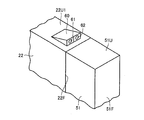
- the camera 60 of the third embodiment is fixed to a counterweight 51 attached to the front end 2F of the vehicle body frame 2 (the front end 22F of the front frame 22).
- the counterweight 51 has an upper surface 51U and a front surface 51F.
- the camera 60 of the third embodiment is fixed to the upper surface 51U of the counterweight 51.
- the camera 60 includes the first imaging unit 61 and the second imaging unit 62 described in the first embodiment.
- the camera 60 is disposed in front of the rotation shaft 11 ⁇ / b> A that is the rotation center of the front wheel 11.
- the camera 60 is disposed in front of the front end 2F of the vehicle body frame 2 (the front end 22F of the front frame 22).
- the three-dimensional shape of the terrain that the front wheel 11 is about to pass in front of the vehicle main body can be obtained with high accuracy, as in the first embodiment.
- the camera 60 By disposing the camera 60 on the upper surface 51U of the counterweight 51, the camera 60 is disposed more forward than in the first embodiment. Therefore, the constituent elements of the motor grader 1 are unlikely to exist within the angle of view V (FIG. 4) of the camera 60. Since the imaging range IR of the camera 60 can include a wider range of the ground in front of the body frame 2, the three-dimensional shape of the terrain that the front wheel 11 is about to pass through in front of the vehicle body is surely acquired. Can do.
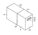
- FIG. 9 is an enlarged perspective view of the front end portion of the front frame 22 of the motor grader 1 based on the fourth embodiment. Similar to the third embodiment, the camera 60 is fixed to a counterweight 51 attached to the front end 2F of the vehicle body frame 2 (the front end 22F of the front frame 22). The camera 60 according to the fourth embodiment is embedded in the counterweight 51. The optical processing units of the first imaging unit 61 and the second imaging unit 62 are exposed on the front surface 51F of the counterweight 51.
- the three-dimensional shape of the terrain that the front wheel 11 is about to pass in front of the vehicle main body can be obtained with high accuracy, as in the first embodiment. Since the camera 60 is disposed so as to be exposed on the front surface 51F of the counterweight 51, the camera 60 is disposed more forward than the first embodiment. Therefore, the constituent elements of the motor grader 1 are unlikely to exist within the angle of view V (FIG. 4) of the camera 60. Since the imaging range IR of the camera 60 can include a wider range of the ground in front of the body frame 2, the three-dimensional shape of the terrain that the front wheel 11 is about to pass through in front of the vehicle body is surely acquired. Can do.
- the counter weight 51 is provided to increase the downward load applied to the front wheel 11.
- the counter weight 51 may not be attached to the front frame 22.
- the camera 60 may be fixed to the front frame 22 as described in the first and second embodiments.
- FIG. 10 is a schematic diagram showing a scanning range by the radar.
- the motor grader 1 includes the camera 60 for imaging the current terrain has been described.
- the motor grader 1 may include a radar 70 that scans the current landform as shown in FIG.
- the three-dimensional shape of the terrain that the front wheel 11 is about to pass in front of the vehicle body can be obtained with high accuracy. Since the three-dimensional shape of the terrain that the front wheel 11 is about to pass through can be acquired with high accuracy, the terrain data can be used for the operation of the blade 42 to perform highly accurate and highly efficient leveling work.
- the motor grader 1 as an example of the work vehicle in the embodiment includes a vehicle body frame 2 and a blade 42.
- the body frame 2 includes a front frame 22 and a rear frame 21.
- the blade 42 is disposed between the front end 2F of the vehicle body frame 2 and the rear end 2R of the vehicle body frame 2.
- the motor grader 1 further includes a sensor configured to acquire the current topography in front of the body frame 2.
- the sensor may be a camera 60 that captures the current terrain as shown in FIGS.
- the sensor may be a radar 70 for manipulating the current terrain as shown in FIG.
- the sensor is attached to the front frame 22.
- the sensor is disposed in front of the blade 42.
- the motor grader 1 in the embodiment can measure the current landform in front of the body frame 2 using a sensor. Since the shape of the terrain that the front wheel 11 is about to pass through can be acquired with high accuracy, the terrain data can be used for the operation of the blade 42 to perform highly accurate and highly efficient leveling work.
- the sensor is disposed at the front end portion of the front frame 22.
- the sensor can be arranged at a position closer to the ground in front of the vehicle body frame 2 where the current terrain should be acquired using the sensor, and the current terrain in front of the vehicle body frame 2 can be acquired more accurately. Can do.
- the constituent elements of the motor grader 1 are less likely to be present within the angle of view of the sensor, and the constituent elements of the motor grader 1 are suppressed from becoming an obstacle to acquisition of the current landform using the sensor. Thereby, the present landform of the wider range ahead of the body frame 2 can be acquired reliably.
- the motor grader 1 further includes an articulate cylinder 23 attached between the front frame 22 and the rear frame 21.
- the front frame 22 can be rotated with respect to the rear frame 21, and the front frame 22 can be bent with respect to the rear frame 21.
- the turning radius at the time of turning of the motor grader 1 can be made small.
- groove excavation work and slope cutting work by offset traveling of the motor grader 1 can be performed. In the offset traveling, the direction in which the front frame 22 is bent with respect to the rear frame 21 and the direction in which the front wheels 11 are turned with respect to the front frame 22 are opposite to each other so that the motor grader 1 travels straight. That means.
- the motor grader 1 further includes a front wheel 11 rotatably attached to the front frame 22.
- the sensor is arranged in front of the rearmost part 11R of the front wheel 11. In this way, the current terrain ahead of the front wheel 11 can be reliably acquired using the sensor, and therefore the shape of the terrain that the front wheel 11 is about to pass through can be accurately acquired.
- the front frame 22 has an inclined region in which the upper surface 22U is inclined toward the front obliquely downward direction.
- the sensor is disposed in the inclined area. By arranging the sensor using the inclined region, the sensor can be easily arranged. Moreover, since it is suppressed that a sensor obstructs the operator's visual field in the cab 3, an operator's visual field can be ensured widely.
- the senor is fixed to the upper surface 22U of the front frame 22.
- the sensor By fixing the sensor to the upper surface 22U, which is the uppermost position of the front frame 22, it is possible to reliably acquire a wider range of current landforms in front of the body frame 2.
- the sensor is fixed to the left and right sides of the front frame 22.
- the sensors By arranging the sensors at intervals in the left-right direction, the current landform in front of the body frame 2 can be accurately imaged.
- the motor grader 1 further includes a counterweight 51 as an example of an attachment attached to the front end 2F of the vehicle body frame 2.
- the sensor is fixed to the counterweight 51.
- the components of the motor grader 1 are less likely to be present within the angle of view of the sensor, and the components of the motor grader 1 are suppressed from becoming an obstacle to acquisition of the current landform using the sensor. .
- the present landform of the wider range ahead of the body frame 2 can be acquired reliably.
- the motor grader 1 has the cab 3, but the motor grader 1 does not necessarily have the cab 3.
- the motor grader 1 is not limited to a specification in which an operator gets on the motor grader 1 and operates the motor grader 1, but may be a specification that operates by remote operation from the outside. In this case, the motor grader 1 does not need the cab 3 for the operator to board, and therefore does not need to have the cab 3.
- 1 motor grader 2 body frame, 2F, 22F front end, 2R rear end, 3 cab, 4 work equipment, 11 front wheel, 11A rotating shaft, 11R rear end, 12 rear wheel, 21 rear frame, 22 front frame, 22L left side, 22R right surface, 22U, 51U top surface, 22U1 front top surface, 22U2 rear top surface, 25 exterior cover, 40 drawbar, 41 turning circle, 42 blade, 44 lift cylinder, 51 counterweight, 51F front surface, 60 camera, 61 first imaging Section, 62 second imaging section, 63, 64 bracket, 70 radar, AX optical axis, IR imaging range, V angle of view.
Landscapes
- Engineering & Computer Science (AREA)
- Remote Sensing (AREA)
- Physics & Mathematics (AREA)
- Radar, Positioning & Navigation (AREA)
- General Engineering & Computer Science (AREA)
- Civil Engineering (AREA)
- Structural Engineering (AREA)
- Mining & Mineral Resources (AREA)
- General Physics & Mathematics (AREA)
- Mechanical Engineering (AREA)
- Electromagnetism (AREA)
- Multimedia (AREA)
- Computer Networks & Wireless Communication (AREA)
- Optics & Photonics (AREA)
- Acoustics & Sound (AREA)
- Measurement Of Optical Distance (AREA)
- Component Parts Of Construction Machinery (AREA)
- Operation Control Of Excavators (AREA)
- Road Paving Machines (AREA)
Abstract
L'invention concerne un engin de chantier qui permet d'obtenir avec précision la forme de terrain actuelle d'une zone sur laquelle un travail doit être réalisé. Dans l'engin de chantier, une niveleuse (1) comprend une ossature de carrosserie de véhicule (2), une lame (42) et une caméra (60). La lame (42) est disposée entre le bord avant (2F) de l'ossature de carrosserie de véhicule (2) et le bord arrière (2R) de l'ossature de carrosserie de véhicule (2). La caméra (60) est configurée pour obtenir la forme de terrain actuelle en face de l'ossature de carrosserie de véhicule (2). La caméra (60) est montée sur l'ossature de carrosserie de véhicule (2). La caméra (60) est disposée davantage vers l'avant que la lame (42).
Priority Applications (2)
| Application Number | Priority Date | Filing Date | Title |
|---|---|---|---|
| US16/082,633 US20190078292A1 (en) | 2016-03-23 | 2017-03-03 | Work vechile |
| CN201780011009.4A CN108603355A (zh) | 2016-03-23 | 2017-03-03 | 作业车辆 |
Applications Claiming Priority (2)
| Application Number | Priority Date | Filing Date | Title |
|---|---|---|---|
| JP2016058838A JP6754594B2 (ja) | 2016-03-23 | 2016-03-23 | モータグレーダ |
| JP2016-058838 | 2016-03-23 |
Publications (1)
| Publication Number | Publication Date |
|---|---|
| WO2017163823A1 true WO2017163823A1 (fr) | 2017-09-28 |
Family
ID=59901161
Family Applications (1)
| Application Number | Title | Priority Date | Filing Date |
|---|---|---|---|
| PCT/JP2017/008527 Ceased WO2017163823A1 (fr) | 2016-03-23 | 2017-03-03 | Engin de chantier |
Country Status (4)
| Country | Link |
|---|---|
| US (1) | US20190078292A1 (fr) |
| JP (1) | JP6754594B2 (fr) |
| CN (1) | CN108603355A (fr) |
| WO (1) | WO2017163823A1 (fr) |
Cited By (6)
| Publication number | Priority date | Publication date | Assignee | Title |
|---|---|---|---|---|
| US11111653B2 (en) | 2017-03-31 | 2021-09-07 | Komatsu Ltd. | Control system for work vehicle, method for setting trajectory of work implement, and work vehicle |
| US11142890B2 (en) | 2018-08-08 | 2021-10-12 | Deere & Company | System and method of soil management for an implement |
| US11180902B2 (en) | 2018-08-08 | 2021-11-23 | Deere & Company | Forward looking sensor for predictive grade control |
| US11193255B2 (en) | 2019-07-31 | 2021-12-07 | Deere & Company | System and method for maximizing productivity of a work vehicle |
| WO2022176586A1 (fr) * | 2021-02-19 | 2022-08-25 | 株式会社小松製作所 | Système de surveillance d'environnement d'une machine de travail, machine de travail et procédé de surveillance d'environnement d'une machine de travail |
| US11891782B2 (en) | 2020-04-30 | 2024-02-06 | Deere & Company | Ground engaging tool control system and method |
Families Citing this family (11)
| Publication number | Priority date | Publication date | Assignee | Title |
|---|---|---|---|---|
| JP6850078B2 (ja) * | 2016-03-23 | 2021-03-31 | 株式会社小松製作所 | モータグレーダ |
| US10883248B2 (en) * | 2018-10-22 | 2021-01-05 | Deere & Company | Road maintenance using stored maintenance passes |
| JP7458155B2 (ja) * | 2019-07-31 | 2024-03-29 | 株式会社小松製作所 | 表示システム、遠隔操作システム、及び表示方法 |
| CN111959622B (zh) * | 2020-07-21 | 2024-09-17 | 山东临工工程机械有限公司 | 一种牵引车 |
| US12209389B2 (en) | 2022-03-04 | 2025-01-28 | Deere &Company | Work vehicle having a work implement and sensors for maintaining a view of an area of interest throughout movement of the work implement |
| US12077948B2 (en) | 2022-03-04 | 2024-09-03 | Deere &Company | System and method for maintaining a view of an area of interest proximate a work vehicle |
| US11680387B1 (en) | 2022-04-21 | 2023-06-20 | Deere & Company | Work vehicle having multi-purpose camera for selective monitoring of an area of interest |
| US12180686B2 (en) | 2022-04-21 | 2024-12-31 | Deere & Company | Work vehicle having enhanced visibility throughout implement movement |
| US12516506B2 (en) | 2022-04-21 | 2026-01-06 | Deere & Company | Work vehicle having controlled transitions between different display modes for a moveable area of interest |
| EP4324988B1 (fr) * | 2022-08-17 | 2025-11-26 | Leica Geosystems Technology A/S | Procédé et système de configuration d'une unité de commande de machine d'une machine de construction |
| US12489860B2 (en) | 2023-03-08 | 2025-12-02 | Deere & Company | Digital panning system and method for a work machine |
Citations (7)
| Publication number | Priority date | Publication date | Assignee | Title |
|---|---|---|---|---|
| JPS5826130A (ja) * | 1981-08-10 | 1983-02-16 | Meidensha Electric Mfg Co Ltd | 土建作業方法 |
| JPH0399061U (fr) * | 1990-01-22 | 1991-10-16 | ||
| JPH05339959A (ja) * | 1992-06-05 | 1993-12-21 | Kensetsusho Tohoku Chiho Kensetsu Kyokucho | モータグレーダの振動抑制装置 |
| JP2000120099A (ja) * | 1999-11-30 | 2000-04-25 | Komatsu Est Corp | モ―タグレ―ダの操作装置 |
| JP2008144379A (ja) * | 2006-12-06 | 2008-06-26 | Shin Caterpillar Mitsubishi Ltd | 遠隔操縦作業機の画像処理システム |
| JP2009541778A (ja) * | 2007-08-02 | 2009-11-26 | インハ インダストリー パートナーシップ インスティテュート | 構造光を使用した土工量算出装置及び方法 |
| JP2010043446A (ja) * | 2008-08-11 | 2010-02-25 | Tokyo Keiki Inc | モータグレーダのブレード高さ制御装置 |
Family Cites Families (77)
| Publication number | Priority date | Publication date | Assignee | Title |
|---|---|---|---|---|
| US3708232A (en) * | 1970-09-16 | 1973-01-02 | R Walsh | Read-out means for locating and positioning objects with respect to a laser beam reference |
| CH529699A (fr) * | 1970-09-17 | 1972-10-31 | Battelle Memorial Institute | Corps allongé en verre renforcé et procédé de fabrication de ce corps |
| US4507910A (en) * | 1983-11-21 | 1985-04-02 | Ezra C. Lundahl, Inc. | Automatic sonar activated height control for a header |
| DE3507570A1 (de) * | 1985-03-04 | 1986-09-04 | Willi Eisen GmbH, 3060 Stadthagen | Verfahren und vorrichtung zur automatischen lenkung eines fahrzeuges, insbesondere eines landwirtschaftlichen fahrzeuges, entlang eines in fahrtrichtung orientierten musters |
| JPS61281915A (ja) * | 1985-06-07 | 1986-12-12 | Kokusai Kogyo Kk | 路面性状計測車両装置 |
| JPS6434202A (en) * | 1987-07-30 | 1989-02-03 | Kubota Ltd | Working wagon of automatic conduct type |
| DE3738221A1 (de) * | 1987-11-11 | 1989-06-08 | Bayerische Motoren Werke Ag | Verfahren und einrichtung zum erkennen des zustandes einer strasse |
| US4899296A (en) * | 1987-11-13 | 1990-02-06 | Khattak Anwar S | Pavement distress survey system |
| US4954962A (en) * | 1988-09-06 | 1990-09-04 | Transitions Research Corporation | Visual navigation and obstacle avoidance structured light system |
| US5327345A (en) * | 1991-02-15 | 1994-07-05 | Laser Alignment, Inc. | Position control system for a construction implement such as a road grader |
| US5442552A (en) * | 1993-03-16 | 1995-08-15 | The Regents Of The University Of California | Robotic cultivator |
| EP0801885B1 (fr) * | 1996-04-19 | 2002-01-09 | Carnegie-Mellon University | Guidage par rapport à ligne de récolte basé sur la vision |
| JPH1088625A (ja) * | 1996-09-13 | 1998-04-07 | Komatsu Ltd | 自動掘削機、自動掘削方法および自動積み込み方法 |
| US5735352A (en) * | 1996-12-17 | 1998-04-07 | Caterpillar Inc. | Method for updating a site database using a triangular irregular network |
| DE19719939A1 (de) * | 1997-05-13 | 1998-11-19 | Claas Ohg | Automatisch lenkbare Erntemaschine |
| US6055042A (en) * | 1997-12-16 | 2000-04-25 | Caterpillar Inc. | Method and apparatus for detecting obstacles using multiple sensors for range selective detection |
| US6173215B1 (en) * | 1997-12-19 | 2001-01-09 | Caterpillar Inc. | Method for determining a desired response to detection of an obstacle |
| JP3720972B2 (ja) * | 1998-01-22 | 2005-11-30 | 株式会社小松製作所 | 地形形状計測装置 |
| US8478492B2 (en) * | 1998-11-27 | 2013-07-02 | Caterpillar Trimble Control Technologies, Inc. | Method and system for performing non-contact based determination of the position of an implement |
| US6278955B1 (en) * | 1998-12-10 | 2001-08-21 | Caterpillar Inc. | Method for automatically positioning the blade of a motor grader to a memory position |
| US6129156A (en) * | 1998-12-18 | 2000-10-10 | Caterpillar Inc. | Method for automatically moving the blade of a motor grader from a present blade position to a mirror image position |
| US6736216B2 (en) * | 2000-05-05 | 2004-05-18 | Leica Geosystems Gr, Llc | Laser-guided construction equipment |
| DE10060903C2 (de) * | 2000-12-07 | 2002-10-31 | Moba Mobile Automation Gmbh | Laser-Höhenregeleinrichtung für eine Baumaschine |
| DE10129136A1 (de) * | 2001-06-16 | 2002-12-19 | Deere & Co | Einrichtung zur selbsttätigen Lenkung eines landwirtschaftlichen Arbeitsfahrzeugs |
| US6661524B2 (en) * | 2001-07-09 | 2003-12-09 | United Defense, L.P. | Vehicle regional scanner |
| DE10214648A1 (de) * | 2002-04-02 | 2003-10-16 | Claas Selbstfahr Erntemasch | Messeinrichtung an einer landwirtschaftlichen Maschine |
| US7068815B2 (en) * | 2003-06-13 | 2006-06-27 | Sarnoff Corporation | Method and apparatus for ground detection and removal in vision systems |
| DE10351861A1 (de) * | 2003-11-06 | 2005-06-09 | Deere & Company, Moline | Verfahren und Lenksystem zum selbsttätigen Lenken einer landwirtschaftlichen Maschine |
| US7325636B2 (en) * | 2004-08-30 | 2008-02-05 | Caterpillar Inc. | Front-wheel drive steering compensation method and system |
| US7184926B2 (en) * | 2005-03-16 | 2007-02-27 | Trimble Navigation Limited | Method for estimating the orientation of a machine |
| US8139109B2 (en) * | 2006-06-19 | 2012-03-20 | Oshkosh Corporation | Vision system for an autonomous vehicle |
| US7865285B2 (en) * | 2006-12-27 | 2011-01-04 | Caterpillar Inc | Machine control system and method |
| KR100758705B1 (ko) * | 2007-02-01 | 2007-09-21 | 위성동 | 도로의 포장상태 자동 조사장치 |
| US9176235B2 (en) * | 2008-04-11 | 2015-11-03 | Caterpillar Trimble Control Technologies Llc | System and method for presenting topographical data for an earthmoving operation |
| US20100076710A1 (en) * | 2008-09-19 | 2010-03-25 | Caterpillar Inc. | Machine sensor calibration system |
| JP5227139B2 (ja) * | 2008-11-12 | 2013-07-03 | 株式会社トプコン | 建設機械 |
| US8169596B2 (en) * | 2009-08-17 | 2012-05-01 | Seegrid Corporation | System and method using a multi-plane curtain |
| US8744693B2 (en) * | 2010-11-22 | 2014-06-03 | Caterpillar Inc. | Object detection system having adjustable focus |
| US8985233B2 (en) * | 2010-12-22 | 2015-03-24 | Caterpillar Inc. | System and method for controlling a rotation angle of a motor grader blade |
| US9970180B2 (en) * | 2011-03-14 | 2018-05-15 | Caterpillar Trimble Control Technologies Llc | System for machine control |
| GB2494414A (en) * | 2011-09-06 | 2013-03-13 | Land Rover Uk Ltd | Terrain visualisation for vehicle using combined colour camera and time of flight (ToF) camera images for augmented display |
| JP2013195086A (ja) * | 2012-03-15 | 2013-09-30 | Komatsu Ltd | 障害物検出機構付きダンプトラック |
| US20130255977A1 (en) * | 2012-03-27 | 2013-10-03 | Caterpillar, Inc. | Control for Motor Grader Curb Operations |
| US20130304331A1 (en) * | 2012-05-10 | 2013-11-14 | Caterpillar, Inc. | Display-Based Control for Motor Grader |
| US9213331B2 (en) * | 2012-12-19 | 2015-12-15 | Caterpillar Inc. | Remote control system for a machine |
| WO2014152470A2 (fr) * | 2013-03-15 | 2014-09-25 | Tk Holdings, Inc. | Détection de trajectoire utilisant un éclairage structuré |
| US9957692B2 (en) * | 2013-03-15 | 2018-05-01 | Hexagon Technology Center Gmbh | System and method for heavy equipment navigation and working edge positioning using an image acquisition device that provides distance information |
| JP6091977B2 (ja) * | 2013-04-22 | 2017-03-08 | 日立建機株式会社 | 建設機械 |
| US20140326471A1 (en) * | 2013-05-03 | 2014-11-06 | Caterpillar Inc. | Motor Grader Cross Slope Control With Articulation Compensation |
| CN203603187U (zh) * | 2013-08-15 | 2014-05-21 | 湖南三一路面机械有限公司 | 一种平地机 |
| US20150070498A1 (en) * | 2013-09-06 | 2015-03-12 | Caterpillar Inc. | Image Display System |
| BE1021107B1 (nl) * | 2013-10-28 | 2016-01-18 | Cnh Industrial Belgium Nv | Zwadsensor voor veldhakselaar |
| JP5602929B1 (ja) * | 2013-11-08 | 2014-10-08 | 株式会社小松製作所 | モータグレーダのリッパー装置およびこれを備えたモータグレーダ |
| WO2015106799A1 (fr) * | 2014-01-14 | 2015-07-23 | Sandvik Mining And Construction Oy | Véhicule minier, système de commande de mine et procédé de cartographie |
| US20140232871A1 (en) * | 2014-05-01 | 2014-08-21 | Caterpillar Inc. | Method for manually calibrating a camera mounted on vehicle |
| US20150376863A1 (en) * | 2014-06-30 | 2015-12-31 | Caterpillar Inc. | Cushion hitch for motor grader |
| JP2016065422A (ja) * | 2014-09-26 | 2016-04-28 | 株式会社日立製作所 | 外界認識装置および外界認識装置を用いた掘削機械 |
| US9807933B2 (en) * | 2014-10-20 | 2017-11-07 | Cnh Industrial America Llc | Sensor equipped agricultural harvester |
| CN204362509U (zh) * | 2014-10-20 | 2015-06-03 | 北京农业信息技术研究中心 | Gnss平地机 |
| WO2016072975A1 (fr) * | 2014-11-04 | 2016-05-12 | Volvo Construction Equipment Ab | Module de bloc de poussée pour extrémité avant de niveleuses motorisées |
| US20160137125A1 (en) * | 2014-11-17 | 2016-05-19 | Caterpillar Inc. | Imaging system using virtual projection geometry |
| US9667875B2 (en) * | 2015-01-21 | 2017-05-30 | Caterpillar Inc. | Vision system and method of monitoring surroundings of machine |
| US20160301863A1 (en) * | 2015-04-10 | 2016-10-13 | Caterpillar Inc. | Image processing system for generating a surround-view image |
| US20160301864A1 (en) * | 2015-04-10 | 2016-10-13 | Caterpillar Inc. | Imaging processing system for generating a surround-view image |
| US9938688B2 (en) * | 2015-07-02 | 2018-04-10 | Caterpillar Inc. | Excavation system providing impact detection |
| US9732502B2 (en) * | 2015-07-02 | 2017-08-15 | Caterpillar Inc. | Excavation system providing impact detection |
| KR101815269B1 (ko) * | 2015-10-15 | 2018-01-04 | 가부시키가이샤 고마쓰 세이사쿠쇼 | 위치 계측 시스템 및 위치 계측 방법 |
| JP6666180B2 (ja) * | 2016-03-23 | 2020-03-13 | 株式会社小松製作所 | モータグレーダの制御方法およびモータグレーダ |
| JP6689638B2 (ja) * | 2016-03-23 | 2020-04-28 | 株式会社小松製作所 | モータグレーダの制御方法およびモータグレーダ |
| WO2017176773A1 (fr) * | 2016-04-08 | 2017-10-12 | Ace/Avant Concrete Construction Co., Inc. | Mesure d'excavation |
| US9885169B2 (en) * | 2016-07-01 | 2018-02-06 | GK Technology, Inc. | Automated backslope cutting system |
| WO2018051742A1 (fr) * | 2016-09-16 | 2018-03-22 | 株式会社小松製作所 | Système de commande pour engin de chantier, procédé de commande de système de commande pour engin de chantier, et engin de chantier |
| US10123475B2 (en) * | 2017-02-03 | 2018-11-13 | Cnh Industrial America Llc | System and method for automatically monitoring soil surface roughness |
| JP6251453B1 (ja) * | 2017-02-09 | 2017-12-20 | 株式会社小松製作所 | 作業車両の周辺監視システム、作業車両、及び作業車両の周辺監視方法 |
| JP6346375B1 (ja) * | 2017-02-09 | 2018-06-20 | 株式会社小松製作所 | 作業車両及び表示装置 |
| US10262411B2 (en) * | 2017-09-01 | 2019-04-16 | Deere & Company | Site scanning using a work machine with a camera |
| US10519631B2 (en) * | 2017-09-22 | 2019-12-31 | Caterpillar Inc. | Work tool vision system |
-
2016
- 2016-03-23 JP JP2016058838A patent/JP6754594B2/ja not_active Expired - Fee Related
-
2017
- 2017-03-03 CN CN201780011009.4A patent/CN108603355A/zh active Pending
- 2017-03-03 WO PCT/JP2017/008527 patent/WO2017163823A1/fr not_active Ceased
- 2017-03-03 US US16/082,633 patent/US20190078292A1/en not_active Abandoned
Patent Citations (7)
| Publication number | Priority date | Publication date | Assignee | Title |
|---|---|---|---|---|
| JPS5826130A (ja) * | 1981-08-10 | 1983-02-16 | Meidensha Electric Mfg Co Ltd | 土建作業方法 |
| JPH0399061U (fr) * | 1990-01-22 | 1991-10-16 | ||
| JPH05339959A (ja) * | 1992-06-05 | 1993-12-21 | Kensetsusho Tohoku Chiho Kensetsu Kyokucho | モータグレーダの振動抑制装置 |
| JP2000120099A (ja) * | 1999-11-30 | 2000-04-25 | Komatsu Est Corp | モ―タグレ―ダの操作装置 |
| JP2008144379A (ja) * | 2006-12-06 | 2008-06-26 | Shin Caterpillar Mitsubishi Ltd | 遠隔操縦作業機の画像処理システム |
| JP2009541778A (ja) * | 2007-08-02 | 2009-11-26 | インハ インダストリー パートナーシップ インスティテュート | 構造光を使用した土工量算出装置及び方法 |
| JP2010043446A (ja) * | 2008-08-11 | 2010-02-25 | Tokyo Keiki Inc | モータグレーダのブレード高さ制御装置 |
Cited By (9)
| Publication number | Priority date | Publication date | Assignee | Title |
|---|---|---|---|---|
| US11111653B2 (en) | 2017-03-31 | 2021-09-07 | Komatsu Ltd. | Control system for work vehicle, method for setting trajectory of work implement, and work vehicle |
| US11142890B2 (en) | 2018-08-08 | 2021-10-12 | Deere & Company | System and method of soil management for an implement |
| US11180902B2 (en) | 2018-08-08 | 2021-11-23 | Deere & Company | Forward looking sensor for predictive grade control |
| US11193255B2 (en) | 2019-07-31 | 2021-12-07 | Deere & Company | System and method for maximizing productivity of a work vehicle |
| US11891782B2 (en) | 2020-04-30 | 2024-02-06 | Deere & Company | Ground engaging tool control system and method |
| WO2022176586A1 (fr) * | 2021-02-19 | 2022-08-25 | 株式会社小松製作所 | Système de surveillance d'environnement d'une machine de travail, machine de travail et procédé de surveillance d'environnement d'une machine de travail |
| JP2022127328A (ja) * | 2021-02-19 | 2022-08-31 | 株式会社小松製作所 | 作業機械の周辺監視システム、作業機械、及び作業機械の周辺監視方法 |
| JP7662352B2 (ja) | 2021-02-19 | 2025-04-15 | 株式会社小松製作所 | 作業機械の周辺監視システム、作業機械、及び作業機械の周辺監視方法 |
| JP2025092752A (ja) * | 2021-02-19 | 2025-06-19 | 株式会社小松製作所 | 周辺監視システム、作業機械、及び作業機械の周辺監視方法 |
Also Published As
| Publication number | Publication date |
|---|---|
| US20190078292A1 (en) | 2019-03-14 |
| CN108603355A (zh) | 2018-09-28 |
| JP2017172185A (ja) | 2017-09-28 |
| JP6754594B2 (ja) | 2020-09-16 |
Similar Documents
| Publication | Publication Date | Title |
|---|---|---|
| JP6754594B2 (ja) | モータグレーダ | |
| CN108603357B (zh) | 机动平路机的控制方法以及机动平路机 | |
| CN108699805B (zh) | 机动平路机的控制方法以及机动平路机 | |
| CN108633293B (zh) | 作业车辆以及显示装置 | |
| JP5546427B2 (ja) | 作業機械の周囲監視装置 | |
| JP6827473B2 (ja) | 作業車両の制御システム、作業車両の制御システムの制御方法および作業車両 | |
| JP6850078B2 (ja) | モータグレーダ | |
| WO2016013490A1 (fr) | Dispositif d'affichage des alentours destiné à une machine réalisant une opération de rotation | |
| WO2017164054A1 (fr) | Procédé de commande de niveleuse, niveleuse, et système de gestion de travail de niveleuse | |
| JP2022090113A (ja) | 作業機械 | |
| US11713560B2 (en) | Hydraulic excavator and system | |
| WO2017056268A1 (fr) | Véhicule de travail | |
| WO2020241640A1 (fr) | Système et procédé d'affichage | |
| JP2017082415A (ja) | 表示システム | |
| WO2022070728A1 (fr) | Système de nivellement automatique | |
| WO2021090678A1 (fr) | Dispositif de surveillance de périphérie pour machine de travail | |
| WO2017056267A1 (fr) | Dispositif d'imagerie | |
| JP2025134295A (ja) | モータグレーダおよびモータグレーダのドローバ姿勢算出方法 | |
| JP2025134297A (ja) | モータグレーダおよびモータグレーダのドローバ姿勢算出方法 | |
| WO2025187259A1 (fr) | Niveleuse et procédé de calcul d'attitude de timon d'une niveleuse | |
| JP2025075525A (ja) | 作業機械および作業機械の取付装置 | |
| WO2024071405A1 (fr) | Système d'affichage d'une image autour d'un véhicule de travail, procédé et véhicule de travail | |
| JP2026000069A (ja) | 遠隔操作支援システム、作業車両の遠隔操作装置、および遠隔操作支援方法 | |
| CN121712951A (zh) | 工程机械及作业系统 | |
| JP2025101847A (ja) | 道路機械 |
Legal Events
| Date | Code | Title | Description |
|---|---|---|---|
| NENP | Non-entry into the national phase |
Ref country code: DE |
|
| 121 | Ep: the epo has been informed by wipo that ep was designated in this application |
Ref document number: 17769868 Country of ref document: EP Kind code of ref document: A1 |
|
| 122 | Ep: pct application non-entry in european phase |
Ref document number: 17769868 Country of ref document: EP Kind code of ref document: A1 |