WO2017163917A1 - アクチュエータ及び触感呈示装置 - Google Patents
アクチュエータ及び触感呈示装置 Download PDFInfo
- Publication number
- WO2017163917A1 WO2017163917A1 PCT/JP2017/009607 JP2017009607W WO2017163917A1 WO 2017163917 A1 WO2017163917 A1 WO 2017163917A1 JP 2017009607 W JP2017009607 W JP 2017009607W WO 2017163917 A1 WO2017163917 A1 WO 2017163917A1
- Authority
- WO
- WIPO (PCT)
- Prior art keywords
- diaphragm
- piezoelectric element
- actuator
- support portion
- vibration
- Prior art date
- Legal status (The legal status is an assumption and is not a legal conclusion. Google has not performed a legal analysis and makes no representation as to the accuracy of the status listed.)
- Ceased
Links
Images



Classifications
-
- H—ELECTRICITY
- H10—SEMICONDUCTOR DEVICES; ELECTRIC SOLID-STATE DEVICES NOT OTHERWISE PROVIDED FOR
- H10N—ELECTRIC SOLID-STATE DEVICES NOT OTHERWISE PROVIDED FOR
- H10N30/00—Piezoelectric or electrostrictive devices
- H10N30/20—Piezoelectric or electrostrictive devices with electrical input and mechanical output, e.g. functioning as actuators or vibrators
- H10N30/202—Piezoelectric or electrostrictive devices with electrical input and mechanical output, e.g. functioning as actuators or vibrators using longitudinal or thickness displacement combined with bending, shear or torsion displacement
-
- B—PERFORMING OPERATIONS; TRANSPORTING
- B06—GENERATING OR TRANSMITTING MECHANICAL VIBRATIONS IN GENERAL
- B06B—METHODS OR APPARATUS FOR GENERATING OR TRANSMITTING MECHANICAL VIBRATIONS OF INFRASONIC, SONIC, OR ULTRASONIC FREQUENCY, e.g. FOR PERFORMING MECHANICAL WORK IN GENERAL
- B06B1/00—Methods or apparatus for generating mechanical vibrations of infrasonic, sonic, or ultrasonic frequency
- B06B1/02—Methods or apparatus for generating mechanical vibrations of infrasonic, sonic, or ultrasonic frequency making use of electrical energy
- B06B1/06—Methods or apparatus for generating mechanical vibrations of infrasonic, sonic, or ultrasonic frequency making use of electrical energy operating with piezoelectric effect or with electrostriction
- B06B1/0644—Methods or apparatus for generating mechanical vibrations of infrasonic, sonic, or ultrasonic frequency making use of electrical energy operating with piezoelectric effect or with electrostriction using a single piezoelectric element
- B06B1/0662—Methods or apparatus for generating mechanical vibrations of infrasonic, sonic, or ultrasonic frequency making use of electrical energy operating with piezoelectric effect or with electrostriction using a single piezoelectric element with an electrode on the sensitive surface
- B06B1/0666—Methods or apparatus for generating mechanical vibrations of infrasonic, sonic, or ultrasonic frequency making use of electrical energy operating with piezoelectric effect or with electrostriction using a single piezoelectric element with an electrode on the sensitive surface used as a diaphragm
-
- G—PHYSICS
- G06—COMPUTING OR CALCULATING; COUNTING
- G06F—ELECTRIC DIGITAL DATA PROCESSING
- G06F3/00—Input arrangements for transferring data to be processed into a form capable of being handled by the computer; Output arrangements for transferring data from processing unit to output unit, e.g. interface arrangements
- G06F3/01—Input arrangements or combined input and output arrangements for interaction between user and computer
-
- G—PHYSICS
- G06—COMPUTING OR CALCULATING; COUNTING
- G06F—ELECTRIC DIGITAL DATA PROCESSING
- G06F3/00—Input arrangements for transferring data to be processed into a form capable of being handled by the computer; Output arrangements for transferring data from processing unit to output unit, e.g. interface arrangements
- G06F3/01—Input arrangements or combined input and output arrangements for interaction between user and computer
- G06F3/016—Input arrangements with force or tactile feedback as computer generated output to the user
-
- G—PHYSICS
- G06—COMPUTING OR CALCULATING; COUNTING
- G06F—ELECTRIC DIGITAL DATA PROCESSING
- G06F3/00—Input arrangements for transferring data to be processed into a form capable of being handled by the computer; Output arrangements for transferring data from processing unit to output unit, e.g. interface arrangements
- G06F3/01—Input arrangements or combined input and output arrangements for interaction between user and computer
- G06F3/03—Arrangements for converting the position or the displacement of a member into a coded form
- G06F3/041—Digitisers, e.g. for touch screens or touch pads, characterised by the transducing means
-
- H—ELECTRICITY
- H02—GENERATION; CONVERSION OR DISTRIBUTION OF ELECTRIC POWER
- H02N—ELECTRIC MACHINES NOT OTHERWISE PROVIDED FOR
- H02N2/00—Electric machines in general using piezoelectric effect, electrostriction or magnetostriction
- H02N2/0005—Electric machines in general using piezoelectric effect, electrostriction or magnetostriction producing non-specific motion; Details common to machines covered by H02N2/02 - H02N2/16
- H02N2/005—Mechanical details, e.g. housings
- H02N2/0055—Supports for driving or driven bodies; Means for pressing driving body against driven body
-
- H—ELECTRICITY
- H02—GENERATION; CONVERSION OR DISTRIBUTION OF ELECTRIC POWER
- H02N—ELECTRIC MACHINES NOT OTHERWISE PROVIDED FOR
- H02N2/00—Electric machines in general using piezoelectric effect, electrostriction or magnetostriction
- H02N2/02—Electric machines in general using piezoelectric effect, electrostriction or magnetostriction producing linear motion, e.g. actuators; Linear positioners ; Linear motors
- H02N2/04—Constructional details
-
- H—ELECTRICITY
- H02—GENERATION; CONVERSION OR DISTRIBUTION OF ELECTRIC POWER
- H02N—ELECTRIC MACHINES NOT OTHERWISE PROVIDED FOR
- H02N2/00—Electric machines in general using piezoelectric effect, electrostriction or magnetostriction
- H02N2/02—Electric machines in general using piezoelectric effect, electrostriction or magnetostriction producing linear motion, e.g. actuators; Linear positioners ; Linear motors
- H02N2/06—Drive circuits; Control arrangements or methods
-
- H—ELECTRICITY
- H10—SEMICONDUCTOR DEVICES; ELECTRIC SOLID-STATE DEVICES NOT OTHERWISE PROVIDED FOR
- H10N—ELECTRIC SOLID-STATE DEVICES NOT OTHERWISE PROVIDED FOR
- H10N30/00—Piezoelectric or electrostrictive devices
- H10N30/20—Piezoelectric or electrostrictive devices with electrical input and mechanical output, e.g. functioning as actuators or vibrators
- H10N30/204—Piezoelectric or electrostrictive devices with electrical input and mechanical output, e.g. functioning as actuators or vibrators using bending displacement, e.g. unimorph, bimorph or multimorph cantilever or membrane benders
- H10N30/2041—Beam type
Definitions
- the present disclosure relates to an actuator and a tactile sensation presentation apparatus.
- an actuator that generates vibration is disposed in a touch sensor or the like.
- the actuator is, for example, a unimorph.
- a vibration target such as a touch sensor
- a tactile sensation is presented to the user who touches the vibration target (see, for example, Patent Document 1).
- the vibration of the actuator is efficiently transmitted to the vibration target, and the actuator is required to be configured with a small number of parts.
- An actuator includes a piezoelectric element, a diaphragm, and a support portion.
- the diaphragm is joined to the piezoelectric element and vibrates according to the displacement of the piezoelectric element.
- the support portion supports the diaphragm.
- the diaphragm and the support portion are integrally molded.
- a tactile sensation providing apparatus includes an actuator having a piezoelectric element, a diaphragm, and a support portion.
- the diaphragm is joined to the piezoelectric element and vibrates according to the displacement of the piezoelectric element.
- the support portion supports the diaphragm.
- the tactile sensation providing apparatus includes a vibration target that transmits vibrations of the diaphragm and presents a tactile sensation to the user.
- the diaphragm and the support portion are integrally molded.
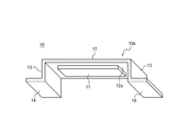
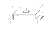
- FIG. It is the perspective view which looked at the structural example of the actuator from the side joined to a housing
- 3 is an example of functional blocks of the tactile sensation providing apparatus according to the first embodiment. It is an example of the cross-sectional shape of a flame
- the tactile sensation presented to the user by the tactile sensation presentation apparatus can be determined according to the magnitude of vibration of the vibration target. It is required that the vibration generated by the actuator is increased so that the vibration is efficiently transmitted to the vibration target so that the vibration target is greatly vibrated.
- a support member for supporting the actuator on a housing or the like is provided.
- a part such as rubber may be used as the support member.
- parts such as rubber are used, the number of parts increases. An increase in the number of parts may lead to a decrease in reliability. An increase in the number of parts may lead to an increase in manufacturing cost.
- the actuator according to the present embodiment can be used for various devices.
- the tactile sensation providing apparatus according to the present embodiment can be a car navigation system or an in-vehicle device such as a steering or power window switch.
- the tactile sensation providing apparatus can be a mobile phone, a smartphone, a tablet PC (Personal Computer), a notebook PC, or the like.
- the tactile sensation providing device is not limited to these, and may be various electronic devices such as a desktop PC, a home appliance, an industrial device or an FA (Factory Automation) device, or a dedicated terminal.
- the drawings used in the following description are schematic. The dimensional ratios on the drawings do not necessarily match the actual ones.
- the tactile sensation providing apparatus 1 includes an actuator 10, a housing 20, and a vibration target 30.
- the actuator 10 includes a piezoelectric element 11, a diaphragm 12, a support part 13, a fixing part 14, and a holding part 15.
- the actuator 10 is joined to the housing 20 via the fixing portion 14.
- the vibration target 30 is joined to the actuator 10 via the holding unit 15.
- the piezoelectric element 11 has a rectangular shape, for example.
- the piezoelectric element 11 is expanded and contracted in various patterns in the longitudinal direction according to the applied voltage signal.
- the piezoelectric element 11 may have other shapes.
- the piezoelectric element 11 may be a piezoelectric film or a piezoelectric ceramic. Piezoelectric ceramics can generate vibrations with greater vibrational energy than piezoelectric films.
- the piezoelectric element 11 may be replaced with a magnetostrictive element.
- the magnetostrictive element expands and contracts according to the applied magnetic field.
- a magnetostrictive element When a magnetostrictive element is used, a coil or the like that converts an applied voltage signal into a magnetic field is also used.
- the diaphragm 12 is a rectangular plate-like member having a predetermined thickness.
- the diaphragm 12 may be a member having another shape.
- the diaphragm 12 is, for example, a thin plate having elasticity.
- the diaphragm 12 may be made of metal, resin, or a composite material such as metal and resin.
- the diaphragm 12 may be a metal thin plate.
- the metal thin plate is also called a shim plate.
- the surface facing the housing 20 side is also referred to as a first main surface 12a.
- the surface facing the vibration target 30 side is also referred to as a second main surface 12b.
- the piezoelectric element 11 is provided on the first main surface 12 a of the diaphragm 12.
- the piezoelectric element 11 is provided so that the longitudinal direction of the piezoelectric element 11 coincides with the longitudinal direction of the diaphragm 12.
- a holding portion 15 is provided on the second main surface 12 b of the diaphragm 12. Each of the piezoelectric element 11 and the holding portion 15 is joined to the diaphragm 12 by a method such as adhesion.
- the structure in which the piezoelectric element 11 is provided on the first main surface 12a of the diaphragm 12 is a so-called monomorph.
- the monomorph expansion / contraction displacement of the piezoelectric element 11 causes bending vibration of the diaphragm 12.
- the diaphragm 12 has the maximum amplitude in the normal direction of the first main surface 12 a at the other end of the diaphragm 12. Vibrates like When both ends of the diaphragm 12 are supported by the housing 20, the diaphragm 12 vibrates so that the amplitude in the normal direction of the first main surface 12 a near the center of the diaphragm 12 is maximized.
- Support portions 13 are provided at both ends in the longitudinal direction of the diaphragm 12.
- the support unit 13 maintains a clearance between the piezoelectric element 11 and the housing 20 so that the diaphragm 12 does not collide with the housing 20 even if the diaphragm 12 vibrates according to the displacement of the piezoelectric element 11.
- the support portion 13 is a thin plate having elasticity, for example, like the diaphragm 12.
- the support portion 13 may be made of the same material as the diaphragm 12 or may be made of a different material.
- the fixing unit 14 may be fixed to the housing 20 by, for example, screwing or bonding.
- the fixed portion 14 may be a thin plate having elasticity, for example, like the diaphragm 12.
- the fixing portion 14 may be made of the same material as the diaphragm 12 or may be made of a different material.
- the diaphragm 12, the support portion 13, and the fixed portion 14 are integrally molded.
- a member in which the diaphragm 12, the support portion 13, and the fixing portion 14 are integrally molded is also referred to as a frame 10 a of the actuator 10.
- the frame 10a according to the present embodiment is composed of the same material as a whole.
- the frame 10a may be integrally formed by, for example, bending a single metal thin plate by sheet metal processing.
- the frame 10a may be integrally molded by welding the diaphragm 12, the support portion 13, and the fixed portion 14, respectively.
- the frame 10a may be made by integral molding of resin.
- the holding unit 15 may be made of, for example, a rubber material.
- the holding part 15 is not limited to a rubber material or the like, and may be made of another material such as a metal.
- the holding part 15 is provided on the second main surface 12 b side of the diaphragm 12.
- the holding part 15 is joined to the diaphragm 12 by using a method such as adhesion.
- the holding portion 15 is provided near the center on the second main surface 12b side.
- the position where the holding part 15 is provided is not limited to the vicinity of the center.
- the holding unit 15 may be provided in a portion having the maximum amplitude of the diaphragm 12.
- the vibrating object 30 is bonded to the holding unit 15 by using a method such as adhesion.
- the holding unit 15 may have a large elastic coefficient in the vibration direction of the diaphragm 12, that is, the normal direction of the first main surface 12a, so that the vibration of the diaphragm 12 is efficiently transmitted to the vibration target 30.
- the holding part 15 may have a small elastic coefficient in a direction parallel to the first main surface 12 a of the diaphragm 12.
- the actuator 10 is joined to the housing 20 by the fixing portion 14.
- the housing 20 has a larger mass and higher rigidity than the actuator 10.
- the housing 20 is assumed to be a rigid body.
- the vibration target 30 may be, for example, a touch sensor 50 (see FIG. 3) or a switch provided in the device.
- the actuator 10 is joined to the vibration target 30 by the holding unit 15.
- vibration generated by the actuator 10 is mainly transmitted to the vibration target 30. By transmitting vibration from the actuator 10 to the vibration target 30, the vibration target 30 can present a tactile sensation to the touched user.
- the tactile sensation providing apparatus 1 further includes a controller 40.
- the controller 40 can be configured by a processor or a microcomputer that can execute application software.
- the controller 40 may appropriately include a storage unit configured by a memory or the like that can store various types of information as necessary.
- the controller 40 is connected to the actuator 10.
- the controller 40 outputs a drive signal to the actuator 10.
- the drive signal may be a voltage signal applied to the piezoelectric element 11 of the actuator 10.
- the piezoelectric element 11 expands and contracts in the longitudinal direction according to the drive signal acquired from the controller 40.
- the diaphragm 12 of the actuator 10 exemplified in FIGS. 1, 2A and 2B bends according to the displacement of the piezoelectric element 11.
- the piezoelectric element 11 When the piezoelectric element 11 is displaced in a direction contracting in the longitudinal direction of the diaphragm 12, the diaphragm 12 bends so that the second main surface 12b side is convex.
- the piezoelectric element 11 is displaced in a direction extending in the longitudinal direction of the diaphragm 12, the diaphragm 12 is bent so that the first main surface 12a side is convex.
- the displacement of the piezoelectric element 11 is converted into vibration in the normal direction of the first main surface 12a of the diaphragm 12.
- the piezoelectric element 11 is displaced only in the direction of contraction in response to application of a voltage signal.
- the diaphragm 12 vibrates between a state bent so that the second main surface 12b side is convex and a normal straight state.
- the displacement of the piezoelectric element 11 is not limited to the direction in which the piezoelectric element 11 contracts in response to the application of the voltage signal.
- the piezoelectric element 11 may be configured to be displaced in an extending direction in response to application of a voltage signal, or may be configured to be displaced in either an extending direction or a contracting direction.
- the controller 40 drives the actuator 10 to vibrate the diaphragm 12.
- the vibration of the diaphragm 12 is transmitted to the vibration target 30 through the holding unit 15.
- the tactile sensation is presented to the user who touched the vibration target 30 by the vibration transmitted to the vibration target 30.
- the controller 40 may be connected to a touch sensor 50 as shown in FIG. 3, for example.
- the controller 40 may output a drive signal to the actuator 10 according to the signal acquired from the touch sensor 50.
- the touch sensor 50 may be the vibration target 30 of the tactile sensation providing apparatus 1.
- the touch sensor 50 detects that the user is touching the vibration target 30.
- the controller 40 vibrates the vibration target 30 when the user is touching the vibration target 30. By doing so, the tactile sensation providing apparatus 1 can present a tactile sensation to the user who has touched the vibration target 30.
- the touch sensor 50 may be provided as a separate configuration from the vibration target 30 of the tactile sensation providing apparatus 1.
- the frame 10 a of the actuator 10 is elastically deformed according to the driving of the actuator 10.
- the support portion 13 is substantially upright with respect to the fixed portion 14 as illustrated in FIGS. 1, 2A, and 2B.
- the piezoelectric element 11 is not expanded and contracted, the support portion 13 is substantially upright with respect to the fixed portion 14.
- the piezoelectric element 11 is displaced in the contracting direction, as shown in FIG. 4, the diaphragm 12 bends so that the second main surface 12b side is convex.
- the upper portion of the support portion 13 is pulled by the diaphragm 12 according to the bending of the diaphragm 12.
- the lower part of the support part 13 is fixed by a fixing part 14. As a result, the support part 13 is inclined. Compared with the frame 10a illustrated in FIGS. 1, 2A, and 2B, the angle formed by the diaphragm 12 and the support portion 13 and the angle formed by the support portion 13 and the fixing portion 14 are larger. .
- the joint portion between the diaphragm 12 and the support portion 13 and the joint portion between the support portion 13 and the fixing portion 14 are elastically deformed so as not to disturb the vibration of the diaphragm 12.
- the support portion 13 may be bent and function like a leaf spring.
- the angle formed by the diaphragm 12 and the support portion 13 and the angle formed by the support portion 13 and the fixed portion 14 may be obtuse.
- the cross-sectional shape of the support portion 13 may be a zigzag folded shape.
- the support unit 13 may be configured to transmit vibration to the vibration target 30 via the holding unit 15 without absorbing vibration of the diaphragm 12 as much as possible.
- the support portion 13 may be configured such that the elastic coefficient in the vibration direction of the diaphragm 12 increases and the elastic coefficient in the expansion / contraction direction of the piezoelectric element 11 decreases.
- the vibration direction of the diaphragm 12 corresponds to the normal direction of the first main surface 12 a of the diaphragm 12.
- the expansion / contraction direction of the piezoelectric element 11 corresponds to the longitudinal direction of the first main surface 12 a of the diaphragm 12.
- the support portion 13 may be configured such that the end portion of the diaphragm 12 is displaced in the longitudinal direction larger than the normal direction of the diaphragm 12 in accordance with the expansion and contraction of the piezoelectric element 11.
- the support portion 13 is configured so that the displacement of the end portion of the vibration plate 12 in the normal direction of the vibration plate 12 is reduced, the vibration of the vibration plate 12 is efficiently transmitted to the vibration target 30.
- the support portion 13 is configured so that the displacement of the end portion of the diaphragm 12 in the longitudinal direction of the diaphragm 12 is increased, vibration attenuation of the diaphragm 12 is reduced.
- the diaphragm 12 and the support portion 13 are integrally molded. Compared with the case where the diaphragm 12 and the support portion 13 are configured as separate components, the vibration attenuation of the diaphragm 12 generated according to the expansion and contraction displacement of the piezoelectric element 11 is reduced by the support portion 13, and the component The number of points and assembly man-hours are reduced. In addition, by not using an adhesive between the diaphragm 12 and the support portion 13, an average failure interval is extended and a yield at the time of assembly is improved. The average failure interval is also called MTBF (Mean Time Between Failure).
- MTBF Mel Time Between Failure
- the frame 10a of the actuator 10 is composed of the same material as a whole.
- the material of the diaphragm 12 and the material of the support portion 13 are different from each other.
- the configuration example of the tactile sensation providing apparatus 1 according to the second embodiment shown in FIG. 6 has points that are different from those in FIG. Hereinafter, differences from FIG. 1 will be described.
- the diaphragm 12 may be a thin plate having elasticity, for example, as in the first embodiment.
- the support part 13 shall be comprised with a resin material.
- the resin material may be a rubber material such as silicon rubber, or may be a sponge material such as a hard sponge.
- the support unit 13 is configured to be elastically deformed so as to reduce the vibration attenuation of the diaphragm 12.
- the support portion 13 is directly joined to the housing 20 by a method such as adhesion.
- the diaphragm 12 and the support portion 13 are integrally molded.
- the diaphragm 12 and the support portion 13 may be integrally formed by molding a resin that becomes the support portion 13 around the metal diaphragm 12.
- the diaphragm 12 and the support part 13 may be integrally formed by fitting the support part 13 made of resin in the fitting part provided on the metal diaphragm 12.
- the diaphragm 12 and the support portion 13 may be integrally formed by applying a primer to a joint surface provided on the surface of the metal diaphragm 12 and molding a resin on the joint surface.
- the diaphragm 12 and the support portion 13 may be integrally formed by performing fine processing on a joint surface provided on the surface of the metal diaphragm 12 and molding a resin on the joint surface.
- the diaphragm 12 and the support portion 13 made of different materials are integrally formed.
- the vibration attenuation of the diaphragm 12 generated according to the displacement of the piezoelectric element 11 can be reduced by the support portion 13, and the component The number of points and assembly man-hours can be reduced.
- the average failure interval can be extended and the yield during assembly can be improved.
- the actuator 10 may be configured not to include the fixing unit 14.
- the end portion of the support portion 13 is joined to the housing 20 by adhesion or the like.
- the end portion of the support portion 13 may be configured to be swingable about the joined portion.
- the number of parts can be reduced, and reliability can be improved and cost can be reduced.
Landscapes
- Engineering & Computer Science (AREA)
- General Engineering & Computer Science (AREA)
- Theoretical Computer Science (AREA)
- Human Computer Interaction (AREA)
- Physics & Mathematics (AREA)
- General Physics & Mathematics (AREA)
- Mechanical Engineering (AREA)
- Apparatuses For Generation Of Mechanical Vibrations (AREA)
- User Interface Of Digital Computer (AREA)
- General Electrical Machinery Utilizing Piezoelectricity, Electrostriction Or Magnetostriction (AREA)
Abstract
Description
本実施形態に係るアクチュエータは、種々の機器に用いられうる。本実施形態に係る触感呈示装置は、カーナビゲーションシステム、又は、ステアリング若しくはパワーウィンドウのスイッチ等の車載機器とされうる。触感呈示装置は、携帯電話、スマートフォン、タブレット型PC(Personal Computer)、ノートPC等とすることができる。触感呈示装置はこれらに限定されるものではなく、デスクトップPC、家電製品、産業用機器若しくはFA(Factory Automation)機器、又は専用端末等、種々の電子機器とされうる。以下の説明で用いられる図は模式的なものである。図面上の寸法比率等は現実のものとは必ずしも一致していない。
図1に示されるように、本実施形態に係る触感呈示装置1は、アクチュエータ10と、筐体20と、振動対象30とを備える。
図3に示されるように、触感呈示装置1は、コントローラ40をさらに備える。コントローラ40は、アプリケーションソフトウェアを実行可能なプロセッサまたはマイクロコンピュータ等によって構成されうる。コントローラ40は、必要に応じて各種情報を記憶することができるメモリ等によって構成される記憶部等も適宜含みうる。
アクチュエータ10のフレーム10aは、アクチュエータ10の駆動に応じて弾性変形する。圧電素子11に電圧信号が印加されていない場合、図1、図2A及び図2Bに例示されるように、支持部13は、固定部14に対して略直立である。言い換えれば、圧電素子11が伸縮変位していない場合、支持部13は、固定部14に対して略直立である。一方で圧電素子11が縮む方向に変位した場合、図4に示されるように、振動板12は、第2主面12bの側が凸になるように屈曲する。振動板12の屈曲に応じて、支持部13の上部は振動板12に引っ張られる。支持部13の下部は固定部14で固定される。結果として、支持部13は傾く。図1、図2A及び図2Bに例示されるフレーム10aと比較して、振動板12と支持部13とがなす角度、及び、支持部13と固定部14とがなす角度がそれぞれ大きくなっている。
実施形態1では、アクチュエータ10のフレーム10aが全体として同一の材料で構成されるものとした。実施形態2では、振動板12の材料と支持部13の材料とが異なる構成とされるものとする。図6に示される、実施形態2に係る触感呈示装置1の構成例は、図1と共通する点と相違する点とを有する。以下、図1との相違点についての説明がなされる。
実施形態1又は2において、アクチュエータ10は、固定部14を備えない構成とされてよい。この場合、支持部13の端部が、接着等により筐体20に接合される。支持部13の端部は、接合された部分を中心に揺動可能に構成されてよい。
10 アクチュエータ
10a フレーム
11 圧電素子
12 振動板
12a 第1主面
12b 第2主面
13 支持部
14 固定部
15 保持部
20 筐体
30 振動対象
40 コントローラ
50 タッチセンサ
Claims (6)
- 圧電素子と、
前記圧電素子が接合され、前記圧電素子の変位に応じて振動する振動板と、
前記振動板を支持する支持部と
を備え、
前記振動板と前記支持部とが一体成型されている、アクチュエータ。 - 前記振動板と前記支持部とは、それぞれ異なる材料からなる、請求項1に記載のアクチュエータ。
- 前記支持部は、前記圧電素子の変位に応じて、前記振動板の端部が前記振動板の法線方向よりも長手方向に大きく変位するように構成される、請求項1又は2に記載のアクチュエータ。
- 圧電素子と、
前記圧電素子が接合され、前記圧電素子の変位に応じて振動する振動板と、
前記振動板を支持する支持部と
を有するアクチュエータと、
前記振動板の振動が伝達され、ユーザに対して触感を呈示する振動対象と
を備え、
前記振動板と前記支持部とが一体成型されている、触感呈示装置。 - 前記振動板と前記支持部とは、それぞれ異なる材料からなる、請求項4に記載の触感呈示装置。
- 前記支持部は、前記圧電素子の変位に応じて、前記振動板の端部が前記振動板の法線方向よりも長手方向に大きく変位するように構成される、請求項4又は5に記載の触感呈示装置。
Priority Applications (2)
| Application Number | Priority Date | Filing Date | Title |
|---|---|---|---|
| EP17769961.8A EP3442109B1 (en) | 2016-03-24 | 2017-03-09 | Tactile sensation presentation device |
| US16/083,523 US11527704B2 (en) | 2016-03-24 | 2017-03-09 | Actuator and tactile sensation providing apparatus |
Applications Claiming Priority (2)
| Application Number | Priority Date | Filing Date | Title |
|---|---|---|---|
| JP2016060589A JP2017175805A (ja) | 2016-03-24 | 2016-03-24 | アクチュエータ及び触感呈示装置 |
| JP2016-060589 | 2016-03-24 |
Publications (1)
| Publication Number | Publication Date |
|---|---|
| WO2017163917A1 true WO2017163917A1 (ja) | 2017-09-28 |
Family
ID=59901225
Family Applications (1)
| Application Number | Title | Priority Date | Filing Date |
|---|---|---|---|
| PCT/JP2017/009607 Ceased WO2017163917A1 (ja) | 2016-03-24 | 2017-03-09 | アクチュエータ及び触感呈示装置 |
Country Status (4)
| Country | Link |
|---|---|
| US (1) | US11527704B2 (ja) |
| EP (1) | EP3442109B1 (ja) |
| JP (1) | JP2017175805A (ja) |
| WO (1) | WO2017163917A1 (ja) |
Cited By (3)
| Publication number | Priority date | Publication date | Assignee | Title |
|---|---|---|---|---|
| WO2019130773A1 (ja) * | 2017-12-27 | 2019-07-04 | Tdk株式会社 | 振動デバイス |
| JP2019197248A (ja) * | 2018-05-07 | 2019-11-14 | Njコンポーネント株式会社 | 振動伝達装置 |
| WO2019230367A1 (ja) * | 2018-05-28 | 2019-12-05 | 京セラ株式会社 | アクチュエータ及び触感呈示装置 |
Families Citing this family (5)
| Publication number | Priority date | Publication date | Assignee | Title |
|---|---|---|---|---|
| TWI637303B (zh) * | 2017-10-11 | 2018-10-01 | 聯陽半導體股份有限公司 | 觸控裝置及觸控裝置的操作方法 |
| JP7038601B2 (ja) * | 2018-05-28 | 2022-03-18 | 京セラ株式会社 | ユニット及び触感呈示装置 |
| JP7162508B2 (ja) * | 2018-11-28 | 2022-10-28 | 京セラ株式会社 | アクチュエータ及び触感呈示装置 |
| US10852833B2 (en) * | 2019-03-29 | 2020-12-01 | Google Llc | Global and local haptic system and mobile devices including the same |
| JP2022109645A (ja) * | 2021-01-15 | 2022-07-28 | Tdk株式会社 | 振動デバイス |
Citations (3)
| Publication number | Priority date | Publication date | Assignee | Title |
|---|---|---|---|---|
| JP2005258666A (ja) * | 2004-03-10 | 2005-09-22 | Sony Corp | 入力装置および電子機器並びに電子機器の感触フィードバック入力方法 |
| WO2007026736A1 (ja) * | 2005-08-31 | 2007-03-08 | Nec Corporation | 圧電アクチュエータ、音響素子、及び電子機器 |
| JP5452729B2 (ja) * | 2010-10-21 | 2014-03-26 | 京セラ株式会社 | タッチパネル装置 |
Family Cites Families (14)
| Publication number | Priority date | Publication date | Assignee | Title |
|---|---|---|---|---|
| JP3967140B2 (ja) * | 2001-09-18 | 2007-08-29 | 大成プラス株式会社 | 携帯通信装置 |
| JP3798287B2 (ja) * | 2001-10-10 | 2006-07-19 | Smk株式会社 | タッチパネル入力装置 |
| US7336266B2 (en) * | 2003-02-20 | 2008-02-26 | Immersion Corproation | Haptic pads for use with user-interface devices |
| EP2209201B1 (en) * | 2007-11-13 | 2014-11-05 | Kohei Hayamizu | Power generation unit |
| WO2009141970A1 (ja) * | 2008-05-19 | 2009-11-26 | 株式会社村田製作所 | 振動装置 |
| EP2184664A1 (en) * | 2008-10-30 | 2010-05-12 | Research In Motion Limited | Portable electronic device including touch-sensitive input device and method of controlling same |
| KR101067066B1 (ko) * | 2009-04-03 | 2011-09-22 | 삼성전기주식회사 | 터치스크린 장치 |
| JP5116902B2 (ja) * | 2011-01-15 | 2013-01-09 | 京セラ株式会社 | 電子機器、およびこれを備えた携帯端末 |
| US9559688B2 (en) * | 2012-04-11 | 2017-01-31 | Ford Global Technologies, Llc | Proximity switch assembly having pliable surface and depression |
| KR20130137960A (ko) * | 2012-06-08 | 2013-12-18 | 삼성전자주식회사 | 전기활성 폴리머를 이용한 액추에이터 및 이를 구비한 전자기기 |
| JP5781495B2 (ja) * | 2012-12-28 | 2015-09-24 | 京セラドキュメントソリューションズ株式会社 | タッチパネル装置 |
| KR101319974B1 (ko) * | 2013-05-20 | 2013-10-18 | 주식회사 이노칩테크놀로지 | 압전 진동 장치 |
| JP5768198B1 (ja) * | 2014-12-02 | 2015-08-26 | 太陽誘電株式会社 | 電気音響変換装置 |
| FR3091414B1 (fr) * | 2018-12-31 | 2023-05-12 | Hap2U | Actionneurs piézoélectriques à déformation amplifiée |
-
2016
- 2016-03-24 JP JP2016060589A patent/JP2017175805A/ja active Pending
-
2017
- 2017-03-09 WO PCT/JP2017/009607 patent/WO2017163917A1/ja not_active Ceased
- 2017-03-09 US US16/083,523 patent/US11527704B2/en active Active
- 2017-03-09 EP EP17769961.8A patent/EP3442109B1/en active Active
Patent Citations (3)
| Publication number | Priority date | Publication date | Assignee | Title |
|---|---|---|---|---|
| JP2005258666A (ja) * | 2004-03-10 | 2005-09-22 | Sony Corp | 入力装置および電子機器並びに電子機器の感触フィードバック入力方法 |
| WO2007026736A1 (ja) * | 2005-08-31 | 2007-03-08 | Nec Corporation | 圧電アクチュエータ、音響素子、及び電子機器 |
| JP5452729B2 (ja) * | 2010-10-21 | 2014-03-26 | 京セラ株式会社 | タッチパネル装置 |
Non-Patent Citations (1)
| Title |
|---|
| See also references of EP3442109A4 * |
Cited By (9)
| Publication number | Priority date | Publication date | Assignee | Title |
|---|---|---|---|---|
| WO2019130773A1 (ja) * | 2017-12-27 | 2019-07-04 | Tdk株式会社 | 振動デバイス |
| JP2019118009A (ja) * | 2017-12-27 | 2019-07-18 | Tdk株式会社 | 振動デバイス |
| JP2019197248A (ja) * | 2018-05-07 | 2019-11-14 | Njコンポーネント株式会社 | 振動伝達装置 |
| WO2019216111A1 (ja) * | 2018-05-07 | 2019-11-14 | Njコンポーネント株式会社 | 振動伝達装置 |
| JP7313799B2 (ja) | 2018-05-07 | 2023-07-25 | Njコンポーネント株式会社 | 振動伝達装置 |
| WO2019230367A1 (ja) * | 2018-05-28 | 2019-12-05 | 京セラ株式会社 | アクチュエータ及び触感呈示装置 |
| JP2019207504A (ja) * | 2018-05-28 | 2019-12-05 | 京セラ株式会社 | アクチュエータ及び触感呈示装置 |
| JP7154040B2 (ja) | 2018-05-28 | 2022-10-17 | 京セラ株式会社 | アクチュエータ及び触感呈示装置 |
| US11620882B2 (en) | 2018-05-28 | 2023-04-04 | Kyocera Corporation | Actuator and tactile sensation providing apparatus |
Also Published As
| Publication number | Publication date |
|---|---|
| US11527704B2 (en) | 2022-12-13 |
| JP2017175805A (ja) | 2017-09-28 |
| EP3442109A4 (en) | 2019-11-20 |
| EP3442109A1 (en) | 2019-02-13 |
| EP3442109B1 (en) | 2025-06-18 |
| US20190081231A1 (en) | 2019-03-14 |
Similar Documents
| Publication | Publication Date | Title |
|---|---|---|
| WO2017163917A1 (ja) | アクチュエータ及び触感呈示装置 | |
| JP6955843B2 (ja) | アクチュエータ及び触感呈示装置 | |
| US11877515B2 (en) | Actuator and tactile sensation providing apparatus | |
| JP6626755B2 (ja) | アクチュエータ及び触感呈示装置 | |
| US10969868B2 (en) | Tactile sensation providing apparatus | |
| JP7162508B2 (ja) | アクチュエータ及び触感呈示装置 | |
| JP7154040B2 (ja) | アクチュエータ及び触感呈示装置 | |
| JP6613153B2 (ja) | 触感呈示装置 | |
| JP6811297B2 (ja) | 触感呈示装置 | |
| JP6926029B2 (ja) | 構造体及び触感呈示装置 | |
| KR102216082B1 (ko) | 유닛 및 촉감 제시 장치 | |
| WO2017130768A1 (ja) | 触感呈示装置 |
Legal Events
| Date | Code | Title | Description |
|---|---|---|---|
| NENP | Non-entry into the national phase |
Ref country code: DE |
|
| WWE | Wipo information: entry into national phase |
Ref document number: 2017769961 Country of ref document: EP |
|
| ENP | Entry into the national phase |
Ref document number: 2017769961 Country of ref document: EP Effective date: 20181024 |
|
| 121 | Ep: the epo has been informed by wipo that ep was designated in this application |
Ref document number: 17769961 Country of ref document: EP Kind code of ref document: A1 |
|
| WWG | Wipo information: grant in national office |
Ref document number: 2017769961 Country of ref document: EP |