WO2017164009A1 - 営農支援システム、営農支援方法、制御装置、通信端末、制御方法、及び、制御プログラムが記録された記録媒体 - Google Patents
営農支援システム、営農支援方法、制御装置、通信端末、制御方法、及び、制御プログラムが記録された記録媒体 Download PDFInfo
- Publication number
- WO2017164009A1 WO2017164009A1 PCT/JP2017/010222 JP2017010222W WO2017164009A1 WO 2017164009 A1 WO2017164009 A1 WO 2017164009A1 JP 2017010222 W JP2017010222 W JP 2017010222W WO 2017164009 A1 WO2017164009 A1 WO 2017164009A1
- Authority
- WO
- WIPO (PCT)
- Prior art keywords
- field
- position information
- information
- field area
- communication terminal
- Prior art date
- Legal status (The legal status is an assumption and is not a legal conclusion. Google has not performed a legal analysis and makes no representation as to the accuracy of the status listed.)
- Ceased
Links
Images


Classifications
-
- G—PHYSICS
- G01—MEASURING; TESTING
- G01C—MEASURING DISTANCES, LEVELS OR BEARINGS; SURVEYING; NAVIGATION; GYROSCOPIC INSTRUMENTS; PHOTOGRAMMETRY OR VIDEOGRAMMETRY
- G01C21/00—Navigation; Navigational instruments not provided for in groups G01C1/00 - G01C19/00
- G01C21/26—Navigation; Navigational instruments not provided for in groups G01C1/00 - G01C19/00 specially adapted for navigation in a road network
- G01C21/28—Navigation; Navigational instruments not provided for in groups G01C1/00 - G01C19/00 specially adapted for navigation in a road network with correlation of data from several navigational instruments
- G01C21/30—Map- or contour-matching
- G01C21/32—Structuring or formatting of map data
-
- G—PHYSICS
- G06—COMPUTING OR CALCULATING; COUNTING
- G06Q—INFORMATION AND COMMUNICATION TECHNOLOGY [ICT] SPECIALLY ADAPTED FOR ADMINISTRATIVE, COMMERCIAL, FINANCIAL, MANAGERIAL OR SUPERVISORY PURPOSES; SYSTEMS OR METHODS SPECIALLY ADAPTED FOR ADMINISTRATIVE, COMMERCIAL, FINANCIAL, MANAGERIAL OR SUPERVISORY PURPOSES, NOT OTHERWISE PROVIDED FOR
- G06Q50/00—Information and communication technology [ICT] specially adapted for implementation of business processes of specific business sectors, e.g. utilities or tourism
- G06Q50/02—Agriculture; Fishing; Forestry; Mining
-
- G—PHYSICS
- G06—COMPUTING OR CALCULATING; COUNTING
- G06F—ELECTRIC DIGITAL DATA PROCESSING
- G06F16/00—Information retrieval; Database structures therefor; File system structures therefor
- G06F16/20—Information retrieval; Database structures therefor; File system structures therefor of structured data, e.g. relational data
- G06F16/24—Querying
- G06F16/245—Query processing
- G06F16/2457—Query processing with adaptation to user needs
- G06F16/24573—Query processing with adaptation to user needs using data annotations, e.g. user-defined metadata
-
- G—PHYSICS
- G06—COMPUTING OR CALCULATING; COUNTING
- G06F—ELECTRIC DIGITAL DATA PROCESSING
- G06F16/00—Information retrieval; Database structures therefor; File system structures therefor
- G06F16/20—Information retrieval; Database structures therefor; File system structures therefor of structured data, e.g. relational data
- G06F16/29—Geographical information databases
-
- G—PHYSICS
- G06—COMPUTING OR CALCULATING; COUNTING
- G06Q—INFORMATION AND COMMUNICATION TECHNOLOGY [ICT] SPECIALLY ADAPTED FOR ADMINISTRATIVE, COMMERCIAL, FINANCIAL, MANAGERIAL OR SUPERVISORY PURPOSES; SYSTEMS OR METHODS SPECIALLY ADAPTED FOR ADMINISTRATIVE, COMMERCIAL, FINANCIAL, MANAGERIAL OR SUPERVISORY PURPOSES, NOT OTHERWISE PROVIDED FOR
- G06Q10/00—Administration; Management
- G06Q10/06—Resources, workflows, human or project management; Enterprise or organisation planning; Enterprise or organisation modelling
-
- G—PHYSICS
- G06—COMPUTING OR CALCULATING; COUNTING
- G06V—IMAGE OR VIDEO RECOGNITION OR UNDERSTANDING
- G06V20/00—Scenes; Scene-specific elements
- G06V20/10—Terrestrial scenes
- G06V20/188—Vegetation
-
- G—PHYSICS
- G09—EDUCATION; CRYPTOGRAPHY; DISPLAY; ADVERTISING; SEALS
- G09B—EDUCATIONAL OR DEMONSTRATION APPLIANCES; APPLIANCES FOR TEACHING, OR COMMUNICATING WITH, THE BLIND, DEAF OR MUTE; MODELS; PLANETARIA; GLOBES; MAPS; DIAGRAMS
- G09B29/00—Maps; Plans; Charts; Diagrams, e.g. route diagram
- G09B29/003—Maps
- G09B29/006—Representation of non-cartographic information on maps, e.g. population distribution, wind direction, radiation levels, air and sea routes
- G09B29/007—Representation of non-cartographic information on maps, e.g. population distribution, wind direction, radiation levels, air and sea routes using computer methods
-
- G—PHYSICS
- G09—EDUCATION; CRYPTOGRAPHY; DISPLAY; ADVERTISING; SEALS
- G09B—EDUCATIONAL OR DEMONSTRATION APPLIANCES; APPLIANCES FOR TEACHING, OR COMMUNICATING WITH, THE BLIND, DEAF OR MUTE; MODELS; PLANETARIA; GLOBES; MAPS; DIAGRAMS
- G09B29/00—Maps; Plans; Charts; Diagrams, e.g. route diagram
- G09B29/10—Map spot or coordinate position indicators; Map reading aids
Definitions
- the present invention relates to a farming support system, a farming support method, a control device, a communication terminal, and a control method and control program thereof.
- Patent Document 1 discloses that satellite images are acquired, the satellite images are analyzed, the map information and the satellite images are superimposed, the planting status is estimated, and the real estate registration information database is collated.
- Patent Document 2 discloses a farming support system that allocates workers and equipment for work in a plurality of spaced farm fields.
- Patent Document 3 discloses a system that creates data in which qualities relating to agricultural products are combined, analyzes the created data, and warns a user or the like based on the analysis result.
- Patent Document 1 estimates the planting situation by superimposing the analysis result of the satellite image on the map information. Therefore, according to the technique, the determination accuracy regarding the field area depends on the accuracy of the satellite image. Further, according to the technique, when the obstacle is reflected in the satellite image, the field area cannot be accurately determined.
- One of the objects of the present invention is to provide a technique for solving the above-mentioned problems.
- the control device includes: Receiving means for receiving the position information acquired by the position information acquiring means carried by the worker in the field; First storage means for storing the position information received by the receiving means; Based on the accumulated position information, a generation unit that generates a field area represented by a field identifier in a map including the field; Is provided.
- the control method includes: The position information acquired by the position information acquisition means carried by the operator in the field is received, the received position information is stored in the storage means, and the field identifier is based on the position information stored in the storage means A field area corresponding to is generated on a map including the field.
- the control program is: A reception function for receiving position information acquired by position information acquisition means carried by an operator in the field; A storage function for storing the position information received by the reception function in a storage unit; Based on the accumulated position information, a generation function for generating on the map a field area corresponding to the field identifier; Is executed on the computer.
- a communication terminal includes: An activation means for activating the farming support application; Display means for displaying the field area generated on the map based on the position information acquired and stored by the position information acquisition means carried by the worker in the field by the farming support application; With The display means displays farming information in the field area according to an instruction of the field area.
- a communication terminal control method includes: The farming support application is activated, and the farm support application is used to display the field area generated on the map based on the position information acquired and stored by the position information acquiring means carried by the worker in the field. It controls to display, and when the said display means is instruct
- a communication terminal control program includes: Start function to start farming support application, A display function for displaying, on the display means, the field area generated on the map based on the position information acquired and stored by the position information acquisition means carried by the worker in the field by the farming support application; To the computer, In the display function, the display means displays farming information in the field area according to an instruction from the field area.
- Farming support system An acquisition means for the operator to carry in the field and acquire position information; Storage means for storing the position information acquired by the acquisition means; Generating means for generating on the map a field area corresponding to the field identifier based on the accumulated position information; Display means for displaying the field area generated on the map in an identifiable manner on the communication terminal; Is provided.
- the farming support method is: Position information is acquired by the position information acquisition means carried by the operator in the field, the acquired position information is stored in the storage means, and the field area corresponding to the field identifier is determined based on the stored position information. It produces
- an arrow represents an example of a flow direction of a certain signal (data, information), and therefore a certain signal (data, information) may advance in a direction opposite to the arrow.
- a control apparatus 100 as a first embodiment of the present invention will be described with reference to FIG.
- the control device 100 is a device that supports farming.
- the control device 100 includes a reception unit 101, a first storage unit 102, and a generation unit 103.
- the receiving unit 101 receives the position information acquired by the position information acquiring unit 110 carried by the worker in the field.
- the first accumulation unit 102 accumulates the position information received by the reception unit 101.
- the generation unit 103 generates a field area 131 represented by the field identifier 132 so as to be superimposed on the map image 133 based on the accumulated position information.
- the field area is generated based on the position information acquired by the position information acquisition unit carried by the worker in the field, the field area can be determined with high accuracy.
- a farming support system having an agricultural field management device as a control device will be described.
- a field area represented by a field identifier is generated on a map based on position information acquired by a position information acquisition unit 210 (FIG. 2, which will be described later) carried by an operator in the field.
- the field area is displayed so as to be identifiable on the communication terminal used by the operator for farming support in the field.
- information related to the setting screen used when registering the farm field area is presented to the communication terminal. Therefore, the registration process of the worker in the field is surely smoothly realized.
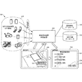
- FIG. 2 is a diagram showing an outline of the configuration and operation of the farming support system 200 according to the present embodiment.
- the farming support system 200 includes a position information acquisition unit 210, an agricultural field management device 220 as a control device, a communication terminal 230, an agricultural field information database 240, and a map information database 250.
- the farm field information database 240 and the map information database 250 may be included in the farm field management apparatus 220.
- the position information acquisition unit 210 may be, for example, a GPS (Global Positioning System) function mounted on various devices carried by the worker in the field. As shown in FIG. 2, the position information acquisition unit 210 is mounted on a smartphone, a tablet, a wearable device, a farming machine, or the like. Note that the position information acquisition unit 210 may be a simple device having a function of acquiring and transmitting position information.
- the field management device 220 acquires position information from the position information acquisition unit 210 using the information stored in the field information database 240 regarding the field and the map information held in the map information database 250, and acquires the acquired position. A field region is generated based on the information.
- the farm field management device 220 creates image information in which the created farm field area is superimposed on the map, and displays the created image information on the communication terminal 230 of the operator. Further, the field management device 220 requests farming support related to the field area by instructing the field area displayed on the communication terminal 230.
- the farm field management apparatus 220 provides a farm field registration screen 233 that allows an operator to register a farm field with a simple operation in response to the process of registering in the farming support application relating to the farm field.
- the communication terminal 230 is, for example, a smartphone, a tablet, or a PC (Personal Computer) used by a farm worker.
- the field area generated by the field management device 220 based on the position information is displayed superimposed on the map.
- the field management device 220 is used when registering the field area 231 in response to the operator's own field area 231 and the registration processing menu 232 being instructed, which are included in the display screen.
- a field registration screen 233 is displayed. On the farm field registration screen 233, information related to the basic farm field area 231 is displayed.
- the operator determines whether the information is correct and, based on the determination result, starts correction input by pressing the correction button 234 or registers the field region 231 by pressing the registration button 235 on the confirmation screen. Determine if it is complete.
- Information relating to the field area 231 includes, for example, owner information, planting information, farming information, harvest information, and history thereof.
- FIG. 3 is a sequence diagram showing an operation procedure of the farming support system 200 according to the present embodiment.
- a position information collection application is activated in step S301.
- the communication terminal 230 is involved in (or relays) the collection of position information
- the communication terminal 230 is added to the position information collection application.
- the position information acquisition unit 210 acquires position information and transmits the acquired position information to the field management device 220. If necessary, the communication terminal 230 relays the process of transmitting the position information to the field management device 220 in step S304.
- the field management device 220 accumulates the collected position information in step S305.
- the field management device 220 generates a field area based on the collected position information in step S311.
- the field management device 220 acquires field information from the field information database 240, and assigns the field ID (identifier) of the generated field area based on the field information.
- the field management device 220 generates a map image in which the field area can be identified by superimposing the field area on the map acquired from the map information database 250.
- step S321 an agricultural field management application is started in step S321.
- step S323 the field management device 220 transmits a map image mapping the field area generated according to the process shown in step S315 to the communication terminal 230 as a start-up screen related to the field management application.
- step S325 the communication terminal 230 displays the received mapped map image.
- step S327 the communication terminal 230 requests the field management device 220 for a field registration screen in response to an instruction of the field area selected by the operator and the registration process related to the field area.
- step S329 the field management device 220 acquires field information from the field information database 240 in response to the communication terminal 230 requesting a field registration screen.
- the field management device 220 generates a field registration screen including field information collected regarding the field area selected by the operator, and transmits the generated field registration screen to the communication terminal 230.
- step S331 the communication terminal 230 instructs the field management device 220 to perform field registration processing related to the field area in accordance with a desired operation performed by the operator on the field registration screen.
- step S333 the farm field management apparatus 220 executes a farm field registration process related to the farmer's farm field area.
- FIG. 4 is a block diagram showing a functional configuration of the field management device 220 as a control device according to the present embodiment.
- the field management device 220 includes a communication control unit 401, a position information reception unit 402, a position information database 403, a field region generation unit 404, a field information acquisition unit 405, a field identifier provision unit 406, and a field region database 407. And comprising.
- the farm field management apparatus 220 includes a map information acquisition unit 408, a mapping image generation unit 409, and a mapping image provision unit 410. Further, the farm field management apparatus 220 includes a farm field registration processing unit 411, a farm field registration screen generation unit 412 included in the farm field registration processing unit 411, and a farm field registration database 413.
- the communication control unit 401 controls communication with the position information acquisition unit 210 and the communication terminal 230. Further, if the field information database 240 and the map information database 250 are independent information providing providers, the communication control unit 401 controls communication with them.
- the location information reception unit 402 receives the location information transmitted from the location information acquisition unit 210 via the communication control unit 401.
- the position information database 403 registers the position information from the position information receiving unit 402 in association with the identifier of the position information acquiring unit 210 if necessary.
- the field area generation unit 404 generates a field area from the position information accumulated in the position information database 403.
- the farm field information acquisition unit 405 acquires the farm field information from the farm field information database 240, in this example, the identifier for identifying the farm field via the communication control unit 401.
- the farm field identifier assigning unit 406 gives a farm field identifier (hereinafter referred to as a farm field ID) to the farm field area generated by the farm field area generating unit 404.
- the field area database 407 stores the field area so as to be searchable by the field ID. With reference to such a field area database 407, on the contrary, it is possible to search the field ID from the field area, and it is also possible to acquire field information from the subsequent field area instructions.
- the map information acquisition unit 408 acquires map information including the field area of interest from the map information database 250.
- the mapping image generation unit 409 maps the farm field area accumulated in the farm field area database 407 on the map to generate a mapping image.
- the mapping image providing unit 410 provides the mapping image generated by the mapping image generating unit 409 to the communication terminal 230 that has activated the field management application.
- the field registration processing unit 411 When the communication terminal 230 activates the field management application and the mapping image is displayed and the mapping field is displayed, the field registration processing unit 411 indicates the target field area and the registration process. Based on the field ID, the field registration screen generation unit 412 generates a field registration screen referring to the field information in the field information database 240. The farm field registration processing unit 411 provides the generated farm field registration screen to the communication terminal 230. Then, the farm field registration processing unit 411 acquires the farm field registration information received from the communication terminal 230. The farm field registration database 413 registers the farm field information instructed by the farm operator from the communication terminal 230 so as to be searchable. This farm field registration information is used in subsequent farming support processing by the farm field management application.
- FIG. 5 is a block diagram illustrating a functional configuration of the communication terminal 230 according to the present embodiment.
- the communication terminal 230 includes a communication control unit 501, an application acquisition unit 502, an application database 503, an application execution unit 504, a display unit 505, and an operation unit 506.
- the communication control unit 501 controls communication between the field management device 220 as a control device and the communication terminal 230.
- the application acquisition unit 502 acquires an application executed by the communication terminal 230 from the server (the field management device 220 in this example) via the communication control unit 501.
- the application database 503 stores applications including a field management application executed by the communication terminal 230.
- the application execution unit 504 executes an application stored in the application database 503.
- Display unit 505 displays notification information received from communication terminal 230.
- the operation unit 506 receives an operation instruction for the communication terminal 230.
- the application execution unit 504 includes a mapping image acquisition unit 541, a display control unit 542, a menu selection unit 543, an agricultural field registration screen acquisition unit 544, an agricultural field registration screen display control unit 545, and an agricultural field registration instruction unit 546.
- a mapping image acquisition unit 541 a display control unit 542
- a menu selection unit 543 a menu selection unit 543
- an agricultural field registration screen acquisition unit 544 a display control unit 544
- an agricultural field registration screen display control unit 545 an agricultural field registration instruction unit 546.
- the mapping image acquisition unit 541 acquires a mapping image obtained by superimposing the field area on the map from the field management device 220 when the field management application is activated.
- the display control unit 542 controls processing for displaying the mapping image acquired by the mapping image acquisition unit 541 and the menu image on the display unit 505.
- the menu selection unit 543 instructs execution of the menu selected by the operation unit 506. In the present embodiment, it is assumed that the farm field registration process is executed.
- the field registration screen acquisition unit 544 requests a field registration screen from the field management device 220 in accordance with an instruction from the menu selection unit 543, and acquires the requested field registration screen from the field management device 220.
- the field registration screen display control unit 545 controls the display unit 505 to display the acquired field registration screen.
- the farm field registration instruction unit 546 registers the farm field via the farm field registration screen according to the operation input to the operation unit 506.
- FIG. 6A is a diagram showing a configuration of the position information database 403 according to the present embodiment.
- the position information database 403 is the position information acquired by the position information acquisition unit 210 and can store the position information collected by the agricultural field management apparatus 220.
- the position information accumulated in the position information database 403 is used as a basis for generating a field area.
- the location information database 403 stores location information acquisition date and time 612 and location information 613 in association with the location acquisition device ID 611.
- the location information database 403 stores the communication terminal 614 in association with the location acquisition device ID 611.
- FIG. 6B is a diagram showing a configuration of the field region database 407 according to the present embodiment.
- the farm field database 407 registers farm field information 621 related to the farm field generated based on the collected position information in association with the farm field ID 622.
- the farm field database 407 further generates an image in which the farm field represented by the farm field information 621 is superimposed on the map.
- the image generated by the field area database 407 is used in a process of acquiring field information based on an instruction regarding the field area received from the communication terminal 230.
- the field area database 407 stores the generated field area information 621 and the field ID 622 in association with each other.
- the generated field area information 621 includes, for example, contour information of the field area, center information of the field area, connection information with other field areas, and the like.
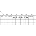
- FIG. 6C is a diagram showing a configuration of the field registration database 413 according to the present embodiment.
- the farm field registration database 413 stores registration information about a farm field of an operator who uses the communication terminal 230 when receiving an instruction about farm field registration from the communication terminal 230.
- the field registration database 413 is predicted by the field registration date 632, owner information 633, planting information 634, farming information 635, harvest information 636, and the field management device 220 in association with the registered field ID 631.
- the farm management prediction information 637 of the farm field is stored.
- the planting information 634, the farm management information 635, and the harvest information 636 include current information and past history information.
- FIG. 7A is a block diagram showing a hardware configuration of a field management device 220 as a control device according to the present embodiment.
- a CPU (Central Processing Unit) 710 is a processor that performs arithmetic control, and implements the functional components shown in FIG. 4 by executing a program.
- a ROM (Read Only Memory) 720 stores initial data and fixed data such as a program and a program.
- the communication control unit 401 controls communication with the position information acquisition unit 210 and the communication terminal 230 via the communication network.
- a RAM (Random Access Memory) 740 is a random access memory that the CPU 710 can use as a work area for temporary storage. In the RAM 740, an area for storing data necessary for realizing the present embodiment is secured.
- the position information 741 is information received from the position information acquisition unit 210.
- the field area information 742 is information indicating the field area generated from the position information.
- the farm field information 743 is information acquired from the farm field information database 240.
- the map information 744 is information acquired from the map information database 250.
- the mapping image 745 including the menu image is an image in which the generated field area is mapped to the map.
- the farm field registration screen 746 is screen information generated in response to receiving a farm field registration request from the communication terminal 230.
- Transmission / reception data 747 is data communicated via the communication control unit 401.
- the storage 750 stores a database, various parameters, or the following data or programs necessary for realizing the present embodiment.
- the location information database 403 is a database that stores location information collected as shown in FIG. 6A.
- the field area database 407 is a database that stores the field area generated from the position information as shown in FIG. 6B.
- the farm field registration database 413 is a database that stores farm field information registered by a registration instruction of the communication terminal 230 as shown in FIG. 6C.
- the storage 750 stores the following programs.
- the control program 751 of the farm field management apparatus is a program that controls the entire farm field management apparatus 220.
- the position information collection module 752 is a module that collects position information from the position information acquisition unit 210.
- the farm field generation module 753 is a module that generates a farm field from the collected position information.
- the mapping image generation module 754 is a module that generates an image obtained by mapping a field area on a map.
- the farm field registration processing module 755 is a module that processes farm field registration from the communication terminal 230 shown in the present embodiment.
- RAM 740 and storage 750 in FIG. 7A do not show programs and data related to general-purpose functions and other feasible functions that the field management device 220 has.
- FIG. 7B is a diagram showing a configuration of the field area generation table 760 according to the present embodiment.
- the field area generation table 760 is a table temporarily generated in the RAM 740 that is used when a field area is generated from the position information collected by the field management device 220.
- the feature extraction information 763 generated based on the collected position information 761 and history information 762, field area information 764, and field ID 765 are stored.
- the feature extraction information 763 includes information (for example, contour, dredging, irrigation, facility construction, farming work, etc.) that is a feature related to the field extracted based on the collected position information 761 and its history information 762. Information extracted from a set of position information) is stored.
- the field area information 764 includes center position information and contour information of the field area. Note that the feature extraction information 763 used when generating the farm field region is not limited to FIG. 7B. Also, the information representing the field area information 764 representing the field area is not limited to FIG. 7B.
- FIG. 7C is a diagram showing a configuration of the superimposed display generation table 770 according to the present embodiment.
- the superimposed display generation table 770 is a table that is temporarily generated in the RAM 740 used in the process of mapping the generated field area to the map.
- the superimposed display generation table 770 stores a map image 771, a certain field area image 772 in the generated map, and a superimposed image 773 obtained by superimposing the image.
- the map image 771 and each field area image 772 include information indicating the size, and a superimposed image 773 is generated so as to match the sizes.
- FIG. 8 is a flowchart showing a processing procedure of the field management device 220 as the control device according to the present embodiment. This flowchart is executed by the CPU 710 in FIG. 7A using the RAM 740, and implements the functional configuration unit in FIG.
- the field management device 220 collects position information from the position information acquisition unit 210 in step S801. In step S803, the field management device 220 executes a field area generation process for generating a field area based on the collected position information.
- the field management device 220 acquires map information from the map information database 250 in step S805. In step S807, the field management device 220 superimposes the generated field area on the map.
- the field management device 220 determines whether or not the field management application has been activated in the communication terminal 230 in step S809. If the farm management application is activated, in this embodiment, the farm management apparatus 220 executes farm registration processing in step S811.
- FIG. 9A is a flowchart showing the procedure of the field area generation processing (step S803 in FIG. 8) according to the present embodiment.
- the field management device 220 acquires the position information collected from the position information database 403 in step S911. If necessary, the field management device 220 acquires history information from the position information database 403 in step S913. In step S915, the farm field management device 220 extracts the farm field features based on the position information or the history information. In step S917, the field management device 220 generates a field area based on the characteristics of the field.
- FIG. 9B is a flowchart showing the procedure of the field registration process (step S811 in FIG. 8) according to the present embodiment.
- step S921 the field management device 220 provides the communication terminal 230 with the mapping image in which the field area on the map is mapped together with the menu image in this example.
- step S923 the farm field management device 220 determines whether a farm field registration request has been received from the communication terminal 230.
- the field management apparatus 220 acquires the field ID representing the field area selected by the communication terminal 230 from the field area database 407 in step S925.
- step S927 the field management device 220 acquires the field information associated with the field ID from the field information database 240, for example.
- the farm field information may be collected by the farm field management apparatus 220.
- step S929 the farm field management device 220 generates a farm field registration screen using the acquired farm field information, and provides the generated farm field registration screen to the communication terminal 230. Then, the farm field management apparatus 220 waits for an instruction regarding farm field registration from the communication terminal 230 in step S931. When there is an instruction regarding field registration, the field management device 220 executes field registration processing for the field registration database 413 in step S933.
- FIG. 10A is a block diagram illustrating a hardware configuration of the communication terminal 230 according to the present embodiment.
- a CPU 1010 is a processor that executes arithmetic control, and implements the functional components shown in FIG. 5 by executing a program.
- the ROM 1020 stores fixed data and programs such as initial data and programs.
- the communication control unit 501 controls communication with the field management device 220 via the communication network.
- the RAM 1040 is a random access memory used by the CPU 1010 as a temporary storage work area. In the RAM 1040, an area capable of storing data necessary for realizing the present embodiment is secured.
- the application 1041 is a downloaded program.
- the mapping image 1042 including the menu image is an image transmitted from the field management device 220 when the field management application is started, and is an image in which the field area is mapped to the map.
- the farm field registration screen information 1043 is screen information received from the farm field management apparatus 220 at the time of farm field registration.
- the field registration information 1044 is field information registered in the field management device 220 from the communication terminal 230.
- Transmission / reception data 1045 is data communicated via the communication control unit 501.
- the input / output data 1046 is data input / output from / to a peripheral device via the input / output interface 1060.
- the storage 1050 stores a database, various parameters, or the following data or programs necessary for realizing the present embodiment.
- the application database 503 is a database in which applications executed on the communication terminal 230 are stored.
- the storage 1050 stores the following programs.
- the communication terminal control program 1051 is a program that controls the entire communication terminal 230.
- the application program 1052 is an application currently being executed, and in this embodiment, is an agricultural field management application.
- the application program 1052 that is a field management application includes a mapping image display module 1053 that displays the received mapping image, a field registration screen display module 1054 that displays the received field registration screen, and a field that instructs field registration.
- a registration instruction module 1055 includes a mapping image display module 1053 that displays the received mapping image, a field registration screen display module 1054 that displays the received field registration screen, and a field that instructs field registration.
- the input / output interface 1060 interfaces input / output with peripheral devices.
- a GPS position acquisition unit 1061 is connected to the input / output interface 1060.
- RAM 1040 and storage 1050 in FIG. 10A do not show programs and data related to general-purpose functions and other realizable functions of the communication terminal 230.
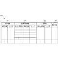
- FIG. 10B is a diagram showing a configuration of the farm field registration table 1070 according to the present embodiment.
- the farm field registration table 1070 is used in a process of transmitting farm field information when the communication terminal 230 registers a farm field.
- the farm field registration table 1070 stores a registration date 1072, owner information 1073, planting information 1074, farming information 1075, harvest information 1076, and the like in association with the farm field ID 1071. This information is transmitted to the field management device 220 and then stored in the field registration database 413 in the field management device 220.
- FIG. 11 is a flowchart showing a processing procedure of the communication terminal 230 according to the present embodiment. This flowchart is executed by the CPU 1010 of FIG. 10A using the RAM 1040, and implements the functional configuration unit of FIG.
- step S1101 the communication terminal 230 waits for an application to start.
- the communication terminal 230 acquires a mapping screen including a menu image from the field management device 220 in step S1103 and displays the acquired mapping image on the display unit 505.
- the communication terminal 230 determines whether there is an instruction for the target field area and the field registration process on the display screen.
- the communication terminal 230 acquires the field registration screen provided from the field management device 220 in step S1107 and displays the acquired field registration number.
- step S1109 the communication terminal 230 determines whether or not there is an instruction to correct the field registration information from the field operator. When there is a correction instruction, the communication terminal 230 receives an input representing the correction content in step S1111. Next, in step S ⁇ b> 1113, the communication terminal 230 waits for an instruction regarding field registration by the field operator. If there is an instruction regarding field registration by a field operator, the communication terminal 230 executes a field registration request to the field management apparatus 220 in step S1115.
- a highly accurate field area is generated based on the position information acquired by the position information acquisition unit carried by the worker in the field, and an image in which the generated field area and the map are superimposed is displayed on the communication terminal.
- the image is used as a key in the farming support registration process. For this reason, according to this embodiment, the registration process to farming support can be performed by a simple operation.
- the farming support system according to this embodiment is a field represented by a field identifier based on predetermined position information acquired by a position information acquisition unit carried by an operator in the field. The difference is that the area is generated on the map. Since other configurations and operations are the same as those of the second embodiment, the same configurations and operations are denoted by the same reference numerals, and detailed description thereof is omitted.
- the predetermined position information may be an entry position and an exit position that cross the field area, or a irrigation section or a ridge that is information surrounding the field area.
- FIG. 12 is a diagram showing an outline of the configuration and operation of the farming support system 1200 according to the present embodiment.
- the same components as those in FIG. 12 are identical to FIG. 12 in FIG. 12, the same components as those in FIG. 12 in FIG. 12, the same components as those in FIG. 12
- the position information acquisition unit 1210 is not limited as shown in FIG. 2, but has a predetermined limit. For example, when the worker transmits position information to the field management device 1220 while walking along the ridge of the field, or when the worker transmits position information to the field management device 1220 while walking along the irrigation pipe. Or the case where the worker walks across the field and enters the field and the point where the worker leaves the field is transmitted to the field management device 1220. In addition, when a farm field is very large, it may be moved by a work vehicle instead of an operator walking.
- the field management device 1220 generates a field area based on position information in which these contents are determined in advance. In this way, a field area can be quickly generated from a small amount of position information.
- the subsequent processing is the same as in FIG.
- FIG. 13 is a diagram showing a configuration of the field area generation table 1360 according to the present embodiment.
- the field area generation table 1360 is used when a field area is generated in accordance with a predetermined position information acquisition condition.
- the field area generation table 1360 includes position information 1362 to be acquired, acquisition information 1363 obtained from the position information 1362, field area information 1364 generated from the acquisition information 1363, and a field ID 1365 associated with the field area information 1364. Is stored in association with the position information acquisition condition 1361.
- the position information acquisition condition 1361 is “ ⁇ ”
- the position information 1362 is position information related to the bag.
- the acquisition information 1363 is area information regarding each bag.
- the field area information 1364 is information on the field area obtained by combining the area information on the straw.
- the position information acquisition condition 1361 is “irrigation pipe”
- the position information 1362 is position information regarding the irrigation pipe.
- the acquisition information 1363 is each irrigation area information.
- the field area information 1364 is information on the field area obtained by combining the irrigation area information.
- the position information 1362 includes position information indicating a point to enter the field area, It is the positional information showing the point which leaves from an agricultural field area
- the acquisition information 1363 is area information having a predetermined shape generated based on the position information regarding the entry point and the position information regarding the exit point.
- the field area information 1364 is area information itself having a predetermined shape. For example, when the position information acquisition condition 1361 is “entrance point and exit point”, the relationship between the field and the entry point and the exit point is determined in advance, and the field region is calculated, or the shape of the field is determined in advance.
- the shape to be arranged based on the entry point and the exit point may be set as the farm field.
- FIG. 14 is a flowchart showing the procedure of the field area generation process (step S803) according to the present embodiment.
- the field management device 1220 sets an acquisition condition related to position information in step S1401.
- the acquisition condition is, for example, “ ⁇ ”, “irrigation pipe”, or “entrance / exit of field”.
- the farm management apparatus 1220 acquires position information corresponding to the acquisition condition from the position information acquisition unit 1210.
- the field management device 1220 generates region information according to a protocol according to the acquisition condition.
- the farm field management apparatus 1220 generates a final farm field area based on the area information.
- an image in which the field area represented by the field identifier is superimposed on the map based on the predetermined position information is generated, so the field area can be easily generated.
- the farming support system which concerns on this embodiment is a field area
- the farming support registration of the worker is promoted by displaying a specific farm field area identifiable on the communication terminal. Since other configurations and operations are the same as those of the second embodiment or the third embodiment, the same configurations and operations are denoted by the same reference numerals, and detailed description thereof is omitted.
- FIG. 15 is a diagram showing an outline of the configuration and operation of the farming support system 1500 according to the present embodiment.
- the same components as those in FIGS. 2 and 12 are denoted by the same reference numerals, and redundant description is omitted.
- the farm field management device 1520 generates a farm field area according to the method shown in the second embodiment or the third embodiment, and creates an image in which the farm field area is superimposed on the map.
- the field management device 1520 displays a predetermined field area in an identifiable manner based on information acquired from the field information database 240 and the field registration database 413.
- the field area 1531 registered in the field management apparatus 1520 that is, under the management
- the farm field 1532 (indicated by a thick frame) is displayed so as to be identifiable.
- the field area 1533 relating to the worker who has the communication terminal 230 connected to the field management apparatus 1520 is displayed in an identifiable manner. With such a display, it is possible to prompt the field operator to perform field registration processing.
- FIG. 16 is a diagram showing a configuration of a specific farm field area table 1600 according to the present embodiment.
- the specific farm field table 1600 is used in a process of identifying a farm field and presenting the identified farm field to an operator of the farm so as to be identifiable.
- the same reference numerals are given to the same components as those in FIG. 6B, and duplicate descriptions are omitted.
- the farm field status 1623 to be identified is stored in association with the farm field information 621 and the farm field ID 622.
- the field situation 1623 to be specified there is information indicating whether it is under the management of the field management device 1520 (that is, whether it has been registered from the operator's communication terminal), or an occurrence of an abnormality (alert) in the field area. Or information indicating that it is the field area of the worker who has accessed the field management device 1520, and the like.
- the farm field management device 1520 displays these farm field situations 1623 on the communication terminal of the farm worker as an identification image. Note that the farm field management device 1520 may display the farm field status 1623 so as to be individually identifiable, or may be displayed in combination so as to be identifiable.
- a specific farm field area (for example, a farm field area during farming support or a farmer field area of a worker) is displayed in an identifiable manner on the communication terminal used by the worker in the farm field, thereby Support registration can be encouraged.
- the farming support system according to the present embodiment uses an image captured from above the field for processing for recognizing the field area. Is different. Since other configurations and operations are the same as those in the second to fourth embodiments, the same configurations and operations are denoted by the same reference numerals, and detailed description thereof is omitted.
- captured images taken from the sky include satellite photographs, images or moving images taken by helicopters, light aircraft, drones, and the like. According to these photographed images, it is possible to recognize the type of crop cultivated in the field, the growth process, the growth situation, or the harvest situation.
- stores a captured image with an imaging area identifier is performed in multiple times, and an agricultural field area
- the estimated field area is referred to, and a field area represented by the field identifier is generated on the map. Further, in the present embodiment, the field area can be corrected by using the estimated field area.
- FIG. 17 is a diagram showing an outline of the configuration and operation of the farming support system 1700 according to this embodiment.
- an aerial image database 1780 is added in addition to FIG. In the aerial image database 1780, satellite images, helicopters, light aircraft, or aerial images taken by drones are stored.
- the farm field management device 1720 superimposes the image acquired from the sky image database 1780 on the image obtained by superimposing the field area generated in the above embodiment on the map, and further adjusts the size and the like.
- the aerial image contains abundant information such as farming targets, growing conditions, and harvesting conditions, and the field areas 1731 of the superimposed images can confirm different situations at a glance.
- the field region can be estimated by accumulating the aerial photograph over a plurality of times and analyzing it, and the field region based on the position information of the above embodiment. Can be used with. For example, it is possible to perform a correction process that takes advantage of each other's advantages, and to generate a more accurate field area.
- FIG. 18 is a diagram showing the configuration of the size adjustment table 1870 according to this embodiment.
- the size adjustment table 1870 is used in the process of adjusting the size when the captured image captured from above is further superimposed on the map on which the field area is superimposed.
- the same components as those in FIG. 7C are denoted by the same reference numerals, and description thereof is omitted.
- the sky image 1873 adjusted in size to the superimposed map image 771 and the field area image 772 and the superimposed image 1874 are stored.
- the sky image 1873 stores the sky photograph information and size.
- the size includes not only the size but also a value obtained by adjusting an angle or the like.
- the sky photograph information is a low-sky photograph taken using a drone or the like, it is obtained by adjusting the size of the plurality of photographs, particularly the image periphery, and combining them.
- FIG. 19 is a diagram showing a configuration of the farm field correction table 1970 according to the present embodiment.
- the farm field correction table 1970 is used in the process of correcting the farm field area generated by the position information from the operator in the farm field based on the characteristics such as the color obtained from the aerial photograph information.
- the farm field correction table 1970 stores a farm field information estimated image 1973 estimated from an aerial photograph and a superimposed image 1974 in which farm field information is corrected.
- the correction regarding the field information does not give priority to the field information estimation image 1973, but the field area image 772 generated based on the position information from the operator in the field and the field information estimation image 1973 estimated from the sky photograph. It is desirable to correct both of them.
- the operator's communication terminal in the farm field displays abundant farm management information in the farm field area by superimposing and displaying the image captured from above the farm field on the farm field area determined based on the position information. Can be.
- the farming support system according to the present embodiment is information related to the correction of the field area included in the instruction operation information received from the operator's communication terminal. Is different in that the field area superimposed on the map can be corrected. Since other configurations and operations are the same as those in the second to fifth embodiments, the same configurations and operations are denoted by the same reference numerals, and detailed description thereof is omitted.
- FIG. 20 is a diagram showing an outline of the configuration and operation of the farming support system 2000 according to the present embodiment.
- the same reference numerals are assigned to the same components as those in FIG. 2, FIG. 12, FIG. 15, or FIG.
- the field area when the field area is different from the communication terminal 230 based on the image in which the field area generated on the map in each of the above embodiments is superimposed, the field area can be corrected.
- the lower left diagram in FIG. 20 shows that the field area to be corrected and the correction process are instructed.
- the field management device 2020 that has received the correction instruction enlarges the designated field area and displays the enlarged field area 2032 on the communication terminal 230 as shown in the lower center diagram. Then, the field operator can correct the field area 2033 by moving the boundary of the field area enlarged on the display screen.
- the field area information stored in the field area database 407 or the field registration database 413 in the field management apparatus 2020 can be corrected.
- FIG. 21 is a diagram showing a configuration of the farm field correction table 2170 according to the present embodiment.
- the field correction table 2170 is used in the process of correcting the field area by an operation on the display screen based on the information regarding the correction of the field area included in the instruction operation information performed by the operator using the communication terminal.
- the same components as those in FIG. 7C are denoted by the same reference numerals, and description thereof is omitted.
- the field correction table 2170 stores a field area image (after correction) 2172 that has been corrected by an operation on the display screen from the field area image (before correction) 772.
- the map image 771 stores a superimposed image 2173 in which the farm field image (after correction) 2172 is superimposed.
- the field area can be corrected by an operator who owns the field or who works on the field, a more accurate field area can be generated.
- the farming support system according to the present embodiment is generated not only based on the registration operation as described above in the second embodiment but also based on position information collected from the worker.
- the farming support information is provided using the field area superimposed and displayed as a main key. Since other configurations and operations are the same as those of the second embodiment, the same configurations and operations are denoted by the same reference numerals, and detailed description thereof is omitted.
- the field management device 220 presents information related to the presentation screen representing the farming state in the field area to the communication terminal based on the instruction operation information received from the communication terminal. Further, the field management device 220 performs processing for presenting information regarding a setting screen used in processing for presenting a farming history regarding a field area or processing for farming in the field area based on the instruction operation information received from the communication terminal. Information related to the presentation screen used is displayed on the communication terminal.
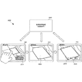
- FIG. 22 is a diagram illustrating an example of an outline of farming support by the farming support system 2200 according to the present embodiment.
- FIG. 22 the same components as those in FIG. 2, FIG. 12, FIG. 15, FIG. 17, or FIG.
- the communication terminal 230 displays the farming status as farming support for the designated field area or displays the farming history in addition to the registration process described in the second embodiment after the farm management application is activated. It can be displayed and farming operations can be displayed.
- the information provided by farming support is not limited to the above example.
- the communication terminal 230 displays the farming information 2234 of the target field area managed by the field management apparatus 220 as shown in the upper right diagram in FIG.
- the farming information 2234 includes detection data such as the amount of sunlight, fertilizer, and moisture, and farming support information such as future weather forecasts and harvest forecasts.
- the communication terminal 230 displays the farming history 2235 in the period from planting to harvesting as shown in the right center diagram.
- the farming history 2235 during the period from planting to harvesting can be realized by displaying a moving image at a high speed.
- each work is displayed as shown in the lower right figure. In the lower right diagram of FIG. 22, the tilling work by the tiller is displayed, for example, the movement history 2236 of the tiller and the animation 2237 regarding the tilling work are displayed, which is used for confirming or improving the farming work or for learning newcomers. You can also
- various farming support information can be provided based on a simple instruction operation using the field area from the communication terminal as a key.
- the present invention may be applied to a system composed of a plurality of devices, or may be applied to a single device. Furthermore, the present invention can also be applied to a case where a control program that realizes the functions of the embodiments is supplied directly or remotely to a system or apparatus. Therefore, in order to realize the functions of the present invention with a computer, a program installed in the computer, a medium storing the program, and a WWW (World Wide Web) server for downloading the program are also included in the scope of the present invention. . In particular, at least a non-transitory computer readable medium that stores a program that causes a computer to execute the processing steps included in the above-described embodiments is included in the scope of the present invention.
- a control device comprising:
- Appendix 2 The control apparatus according to appendix 1, further comprising display control means for controlling the communication terminal used in the field so that the field area generated on the map is identifiable.
- appendix 3 Based on the instruction operation information from the communication terminal used in the field, information on the setting screen for registering the field area or information on the presentation screen for presenting the farming state of the field area is sent to the communication terminal.
- the position information is information representing an entry position included in the position information crossing the field area, and information representing an exit position
- the generation means generates the field area based on the entrance position and the exit position.
- the control device according to any one of appendices 1 to 4.
- the position information is information representing a irrigation section or a fence surrounding the field,
- the generating means generates the field region based on the position information;
- the control device according to any one of appendices 1 to 4.
- the generation unit corrects the field area based on the instruction operation information when receiving instruction operation information for correcting the field area from a communication terminal.
- the control device according to appendices 1 to 6.
- Appendix 8 An acquisition means for acquiring a captured image in which an area including the field is captured from above; The control device according to any one of appendices 1 to 7, wherein the generation unit further superimposes the photographed image having a matching size on the map.
- Appendix 9 A second accumulator that executes a process of accumulating the acquired captured image in association with the imaging region identifier a plurality of times; An estimation means for estimating the field area based on the captured images over a plurality of times; Further comprising The generation means generates a field area represented by the field identifier on the map with reference to the estimated field area.
- the control device according to appendix 8.
- control device (Appendix 10) The control device according to any one of supplementary notes 1 to 9, further comprising display control means for controlling to select and display a specific field area on a communication terminal.
- a reception function for receiving position information acquired by position information acquisition means carried by an operator in the field;
- a storage function for storing the position information received by the reception function in a storage unit;
- a generation function for generating on the map a field area corresponding to the field identifier;
- a recording medium on which a control program for causing a computer to execute is recorded.
- An activation means for activating the farming support application Display means for displaying the field area generated on the map based on the position information acquired and stored by the position information acquisition means carried by the worker in the field by the farming support application; With The said display means is a communication terminal which displays the farming information in the said field area by the instruction
- the farming support application is activated, and the farm support application is used to display the field area generated on the map based on the position information acquired and stored by the position information acquiring means carried by the worker in the field.
- (Appendix 15) Start function to start farming support application, A display function for displaying, on the display means, the field area generated on the map based on the position information acquired and stored by the position information acquisition means carried by the worker in the field by the farming support application; To the computer, In the display function, the display means is a recording medium on which a control program of a communication terminal is recorded, which displays farming information in the field area according to an instruction from the field area.
- (Appendix 16) An acquisition means for the operator to carry in the field and acquire position information; Storage means for storing the position information acquired by the acquisition means; Generating means for generating on the map a field area corresponding to the field identifier based on the accumulated position information; Display means for displaying the field area generated on the map in an identifiable manner on the communication terminal; Farming support system with
- Position information is acquired by the position information acquisition means carried by the operator in the field, the acquired position information is stored in the storage means, and the field area corresponding to the field identifier is determined based on the stored position information.
Landscapes
- Engineering & Computer Science (AREA)
- Theoretical Computer Science (AREA)
- Physics & Mathematics (AREA)
- General Physics & Mathematics (AREA)
- Business, Economics & Management (AREA)
- Remote Sensing (AREA)
- Radar, Positioning & Navigation (AREA)
- Databases & Information Systems (AREA)
- General Engineering & Computer Science (AREA)
- Educational Administration (AREA)
- Strategic Management (AREA)
- Human Resources & Organizations (AREA)
- Economics (AREA)
- Data Mining & Analysis (AREA)
- Health & Medical Sciences (AREA)
- Entrepreneurship & Innovation (AREA)
- General Health & Medical Sciences (AREA)
- Educational Technology (AREA)
- Marketing (AREA)
- Mathematical Physics (AREA)
- Life Sciences & Earth Sciences (AREA)
- Tourism & Hospitality (AREA)
- General Business, Economics & Management (AREA)
- Computational Linguistics (AREA)
- Library & Information Science (AREA)
- Automation & Control Theory (AREA)
- Animal Husbandry (AREA)
- Game Theory and Decision Science (AREA)
- Operations Research (AREA)
- Quality & Reliability (AREA)
- Multimedia (AREA)
- Development Economics (AREA)
- Ecology (AREA)
- Computer Hardware Design (AREA)
- Primary Health Care (AREA)
- Mining & Mineral Resources (AREA)
- Marine Sciences & Fisheries (AREA)
- Agronomy & Crop Science (AREA)
- Management, Administration, Business Operations System, And Electronic Commerce (AREA)
- Instructional Devices (AREA)
Abstract
Description
圃場における作業者が携帯している位置情報取得手段が取得した位置情報を受信する受信手段と、
前記受信手段が受信した位置情報を蓄積する第1蓄積手段と、
蓄積された前記位置情報に基づいて、圃場識別子が表す圃場領域を、前記圃場を含む地図に生成する生成手段と、
を備える。
圃場における作業者が携帯している位置情報取得手段が取得した位置情報を受信し、受信した前記位置情報を蓄積手段に蓄積し、前記蓄積手段に蓄積された前記位置情報に基づいて、圃場識別子に対応する圃場領域を、前記圃場を含む地図に生成する。
前記圃場における作業者が携帯する位置情報取得手段が取得した位置情報を受信する受信機能と、
前記受信機能により受信した位置情報を蓄積手段に蓄積する蓄積機能と、
蓄積された前記位置情報に基づいて、圃場識別子に対応する圃場領域を地図上に生成する生成機能と、
をコンピュータに実行させる。
営農支援アプリケーションを起動する起動手段と、
前記営農支援アプリケーションにより、圃場における作業者が携帯する位置情報取得手段により取得され蓄積された位置情報に基づいて、地図上に生成された圃場領域を表示する表示手段と、
を備え、
前記表示手段は、前記圃場領域の指示により前記圃場領域における営農情報を表示する。
営農支援アプリケーションを起動し、前記営農支援アプリケーションにより、圃場における作業者が携帯している位置情報取得手段により取得され蓄積された位置情報に基づいて、地図上に生成された圃場領域を表示手段に表示するよう制御し、前記表示手段が前記圃場領域を表示している期間に前記圃場領域を指示された場合に、前記圃場領域における営農情報を前記表示手段に表示するよう制御する。
営農支援アプリケーションを起動する起動機能と、
前記営農支援アプリケーションにより、圃場における作業者が携帯する位置情報取得手段により取得され蓄積された位置情報に基づいて、地図上に生成された圃場領域を表示手段に表示する表示機能と、
をコンピュータに実行させ、
前記表示機能において、前記表示手段は、前記圃場領域の指示により前記圃場領域における営農情報を表示する。
圃場において作業者が携帯し、位置情報を取得する取得手段と、
前記取得手段が取得した位置情報を蓄積する蓄積手段と、
蓄積された前記位置情報に基づいて、圃場識別子に対応する圃場領域を地図上に生成する生成手段と、
前記地図上に生成された圃場領域を、通信端末において識別可能に表示する表示手段と、
を備える。
圃場において作業者が携帯している位置情報取得手段により、位置情報を取得し、取得した位置情報を蓄積手段に蓄積し、蓄積された前記位置情報に基づいて、圃場識別子に対応する圃場領域を地図上に生成し、前記地図上に生成された圃場領域を、通信端末において識別可能に表示する。
本発明の第1実施形態としての制御装置100について、図1を用いて説明する。制御装置100は、営農支援をする装置である。
次に、本発明の第2実施形態に係る制御装置としての圃場管理装置を有する営農支援システムについて説明する。本実施形態に係る営農支援システムにおいては、圃場における作業者が携帯する位置情報取得部210(図2、後述する)が取得した位置情報に基づいて、圃場識別子が表す圃場領域を地図上に生成して、圃場において作業者が営農支援に使用する通信端末に圃場領域を識別可能に表示する。そして、作業者による圃場領域を主キー(Primary Key)とした営農支援への登録の指示操作情報に基づいて、圃場領域を登録する場合に用いる設定画面に関する情報が通信端末に提示される。そのため、圃場における作業者の登録処理が間違いなく円滑に実現される。
図2および図3を参照して、本実施形態の営農支援システム200の構成および動作を説明する。
図2は、本実施形態に係る営農支援システム200の構成および動作の概要を示す図である。
図3は、本実施形態に係る営農支援システム200の動作手順を示すシーケンス図である。
図4は、本実施形態に係る制御装置としての圃場管理装置220の機能構成を示すブロック図である。
図5は、本実施形態に係る通信端末230の機能構成を示すブロック図である。
図6Aは、本実施形態に係る位置情報データベース403の構成を示す図である。位置情報データベース403は、位置情報取得部210が取得した位置情報であって、圃場管理装置220が収集した位置情報を蓄積することができる。位置情報データベース403に蓄積された位置情報は、圃場領域を生成する基として使用される。
図6Bは、本実施形態に係る圃場領域データベース407の構成を示す図である。圃場領域データベース407は、収集した位置情報に基づき生成された圃場領域に関する圃場領域情報621を圃場ID622に関連付けて登録する。圃場領域データベース407は、さらに、圃場領域情報621が表す圃場領域を地図に重畳した画像を生成する。圃場領域データベース407によって生成された画像は、通信端末230から受け取った、圃場領域に関する指示に基づいて、圃場情報を取得する処理にて使用される。
図6Cは、本実施形態に係る圃場登録データベース413の構成を示す図である。圃場登録データベース413は、通信端末230から圃場登録に関する指示を受けた場合に、通信端末230を使用する作業者の圃場に関する登録情報を格納する。
図7Aは、本実施形態に係る制御装置としての圃場管理装置220のハードウェア構成を示すブロック図である。
図7Bは、本実施形態に係る圃場領域生成テーブル760の構成を示す図である。圃場領域生成テーブル760は、圃場管理装置220が収集した位置情報から圃場領域を生成する場合に使用されるRAM740に一時生成されるテーブルである。
図7Cは、本実施形態に係る重畳表示生成テーブル770の構成を示す図である。重畳表示生成テーブル770は、生成された圃場領域を地図にマッピングする処理において使用されるRAM740に一時生成されるテーブルである。
図8は、本実施形態に係る制御装置としての圃場管理装置220の処理手順を示すフローチャートである。このフローチャートは、図7AのCPU710がRAM740を使用して実行し、図4の機能構成部を実現する。
図9Aは、本実施形態に係る圃場領域生成処理(図8におけるステップS803)の手順を示すフローチャートである。
図9Bは、本実施形態に係る圃場登録処理(図8におけるステップS811)の手順を示すフローチャートである。
図10Aは、本実施形態に係る通信端末230のハードウェア構成を示すブロック図である。
図10Bは、本実施形態に係る圃場登録テーブル1070の構成を示す図である。圃場登録テーブル1070は、通信端末230が圃場を登録する時に、圃場情報を送信する処理において使用される。
図11は、本実施形態に係る通信端末230の処理手順を示すフローチャートである。このフローチャートは、図10AのCPU1010がRAM1040を使用して実行し、図5の機能構成部を実現する。
次に、本発明の第3実施形態に係る制御装置としての圃場管理装置を有する営農支援システムについて説明する。本実施形態に係る営農支援システムは、第2実施形態と比べ、圃場における作業者が携帯している位置情報取得部によって取得された、あらかじめ決められた位置情報に基づいて、圃場識別子が表す圃場領域を地図に生成する点で異なる。その他の構成および動作は、第2実施形態と同様であるため、同じ構成および動作については同じ符号を付してその詳しい説明を省略する。ここで、あらかじめ決められた位置情報は、圃場領域を横断する入場位置と退場位置とであったり、圃場領域を囲む情報である灌水区画または畝であったりする。
図12は、本実施形態に係る営農支援システム1200の構成および動作の概要を示す図である。なお、図12において、図2と同様の構成要素には同じ参照番号を付して、説明を省略する。
図13は、本実施形態に係る圃場領域生成テーブル1360の構成を示す図である。圃場領域生成テーブル1360は、あらかじめ決められた位置情報の取得条件に対応して、圃場領域を生成する場合に使用される。
図14は、本実施形態に係る圃場領域生成処理(ステップS803)の手順を示すフローチャートである。
次に、本発明の第4実施形態に係る制御装置としての圃場管理装置を有する営農支援システムについて説明する。本実施形態に係る営農支援システムは、第2実施形態および第3実施形態と比べると、圃場における作業者が携帯している位置情報取得部によって取得された位置情報に基づき生成された圃場領域の内、通信端末において特定の圃場領域を識別可能に表示することにより作業者の営農支援登録を促す点に関して異なる。その他の構成および動作は、第2実施形態または第3実施形態と同様であるため、同じ構成および動作については同じ符号を付してその詳しい説明を省略する。
図15は、本実施形態に係る営農支援システム1500の構成および動作の概要を示す図である。なお、図15において、図2や図12と同様の構成要素には同じ参照番号を付して、重複する説明を省略する。
図16は、本実施形態に係る特定圃場領域テーブル1600の構成を示す図である。特定圃場領域テーブル1600は、圃場領域を特定し、特定した圃場領域を識別可能に圃場の作業者に提示する処理にて使用される。図16において、図6Bと同様の構成要素には同じ参照番号を付して、重複する説明を省略する。
次に、本発明の第5実施形態に係る営農支援システムについて説明する。本実施形態に係る営農支援システムは、第2実施形態乃至第4実施形態に示されたシステムと比べると、圃場の上空から撮像された画像を、圃場領域を認識する処理に利用する点にて異なっている。その他の構成および動作は、第2実施形態から第4実施形態と同様であるため、同じ構成および動作については同じ符号を付してその詳しい説明を省略する。
図17は、本実施形態に係る営農支援システム1700の構成および動作の概要を示す図である。なお、図17において、図2、図12または図15と同様の構成要素には同じ参照番号を付して、重複する説明を省略する。
図18は、本実施形態に係るサイズ調整テーブル1870の構成を示す図である。サイズ調整テーブル1870は、上空から撮像された撮影画像を、圃場領域が重畳された地図にさらに重畳する場合に、サイズを調整する処理にて使用される。なお、図18において、図7Cと同様の構成要素には同じ参照番号を付して、説明を省略する。
図19は、本実施形態に係る圃場修正テーブル1970の構成を示す図である。圃場修正テーブル1970は、上空写真情報により得られた色などの特徴により、圃場における作業者からの位置情報により生成された圃場領域を修正する処理において使用される。
次に、本発明の第6実施形態に係る制御装置としての圃場管理装置を有する営農支援システムについて説明する。本実施形態に係る営農支援システムは、第2実施形態乃至第5実施形態に示されたシステムと比べると、作業者の通信端末から受信した指示操作情報に含まれている圃場領域の修正に関する情報に基づいて、地図に重畳表示された圃場領域を修正できる点で異なる。その他の構成および動作は、第2実施形態から第5実施形態と同様であるため、同じ構成および動作については同じ符号を付してその詳しい説明を省略する。
図20は、本実施形態に係る営農支援システム2000の構成および動作の概要を示す図である。なお、図20において、図2、図12、図15あるいは図17と同様の構成要素には同じ参照番号を付して、重複する説明を省略する。
図21は、本実施形態に係る圃場修正テーブル2170の構成を示す図である。圃場修正テーブル2170は、作業者が通信端末を用いて行った指示操作情報に含まれる圃場領域の修正に関する情報に基づいて、表示画面に対する操作により、圃場領域を修正する処理にて使用される。なお、図21において図7Cと同様の構成要素には同じ参照番号を付して、説明を省略する。
次に、本発明の第7実施形態に係る制御装置としての圃場管理装置を有する営農支援システムについて説明する。本実施形態に係る営農支援システムは、第2実施形態乃至第6実施形態と比べると、第2実施形態において上述したような登録操作のみでなく、作業者から収集された位置情報に基づいて生成され、かつ、重畳表示された圃場領域を主キーとして営農支援情報が提供される点にて異なる。その他の構成および動作は、第2実施形態と同様であるため、同じ構成および動作については同じ符号を付してその詳しい説明を省略する。
図22は、本実施形態に係る営農支援システム2200による営農支援の概要の一例を示す図である。なお、図22において、図2、図12、図15、図17あるいは図20と同様の構成要素には同じ参照番号を付して、重複する説明を省略する。
以上、実施形態を参照して本発明を説明したが、本発明は上記実施形態に限定されるものではない。本発明の構成や詳細には、本発明のスコープ内で当業者が理解し得る様々な変更をすることができる。また、それぞれの実施形態に含まれる別々の特徴を如何様に組み合わせたシステムまたは装置も、本発明の範疇に含まれる。
圃場における作業者が携帯している位置情報取得手段が取得した位置情報を受信する受信手段と、
前記受信手段が受信した位置情報を蓄積する第1蓄積手段と、
蓄積された前記位置情報に基づいて、圃場識別子が表す圃場領域を、前記圃場を含む地図に生成する生成手段と、
を備える制御装置。
前記圃場にて使用される通信端末に、前記地図に生成された前記圃場領域を識別可能に表示するよう制御する表示制御手段
を備える付記1に記載の制御装置。
前記圃場にて使用される通信端末からの指示操作情報に基づいて、前記圃場領域を登録する設定画面に関する情報、あるいは、前記圃場領域の営農状態を提示する提示画面に関する情報を、前記通信端末に送信する送信手段
をさらに備える付記1または2に記載の制御装置。
前記圃場にて使用される通信端末からの指示操作情報に基づいて、前記圃場領域での営農履歴を提示する設定画面に関する情報、あるいは、前記圃場における営農作業を提示する提示画面に関する情報を前記通信端末に送信する送信手段
をさらに備える付記1乃至3のいずれか1項に記載の制御装置。
前記位置情報は、前記圃場領域を横断する前記位置情報に含まれる入場位置を表す情報と、退場位置を表す情報とであり、
前記生成手段は、前記入場位置と前記退場位置とに基づき、前記圃場領域を生成する、
付記1乃至4のいずれか1項に記載の制御装置。
前記位置情報は、前記圃場を囲む灌水区画または畝を表す情報であり、
前記生成手段は、前記位置情報に基づき前記圃場領域を生成する、
付記1乃至4のいずれか1項に記載の制御装置。
前記生成手段は、前記圃場領域を修正する指示操作情報を通信端末から受信した場合に、前記指示操作情報に基づいて前記圃場領域を修正する、
付記1乃至6に記載の制御装置。
上空から前記圃場を含む領域が撮影された撮影画像を取得する取得手段
をさらに備え、
前記生成手段は、前記地図に、さらに、サイズを合わせた前記撮影画像を重畳する
付記1乃至7のいずれか1項に記載の制御装置。
複数回、前記取得した撮像画像を撮像領域識別子に関連付けて蓄積する処理を実行する第2蓄積手段と、
前記複数回に亘る撮像画像に基づいて、前記圃場領域を推定する推定手段と、
をさらに備え、
前記生成手段は、前記推定した圃場領域を参照して、前記圃場識別子が表す圃場領域を、前記地図に生成する、
付記8に記載の制御装置。
特定の前記圃場領域を選択して通信端末に表示するよう制御する表示制御手段
を備える付記1乃至9のいずれか1項に記載の制御装置。
圃場における作業者が携帯している位置情報取得手段が取得した位置情報を受信し、受信した前記位置情報を蓄積手段に蓄積し、前記蓄積手段に蓄積された前記位置情報に基づいて、圃場識別子に対応する圃場領域を、前記圃場を含む地図に生成する制御方法。
前記圃場における作業者が携帯する位置情報取得手段が取得した位置情報を受信する受信機能と、
前記受信機能により受信した位置情報を蓄積手段に蓄積する蓄積機能と、
蓄積された前記位置情報に基づいて、圃場識別子に対応する圃場領域を地図上に生成する生成機能と、
をコンピュータに実行させる制御プログラムが記録された記録媒体。
営農支援アプリケーションを起動する起動手段と、
前記営農支援アプリケーションにより、圃場における作業者が携帯する位置情報取得手段により取得され蓄積された位置情報に基づいて、地図上に生成された圃場領域を表示する表示手段と、
を備え、
前記表示手段は、前記圃場領域の指示により前記圃場領域における営農情報を表示する、通信端末。
営農支援アプリケーションを起動し、前記営農支援アプリケーションにより、圃場における作業者が携帯している位置情報取得手段により取得され蓄積された位置情報に基づいて、地図上に生成された圃場領域を表示手段に表示するよう制御し、前記表示手段が前記圃場領域を表示している期間に前記圃場領域を指示された場合に、前記圃場領域における営農情報を前記表示手段に表示するよう制御する制御方法。
営農支援アプリケーションを起動する起動機能と、
前記営農支援アプリケーションにより、圃場における作業者が携帯する位置情報取得手段により取得され蓄積された位置情報に基づいて、地図上に生成された圃場領域を表示手段に表示する表示機能と、
をコンピュータに実行させ、
前記表示機能において、前記表示手段は、前記圃場領域の指示により前記圃場領域における営農情報を表示する、通信端末の制御プログラムが記録された記録媒体。
圃場において作業者が携帯し、位置情報を取得する取得手段と、
前記取得手段が取得した位置情報を蓄積する蓄積手段と、
蓄積された前記位置情報に基づいて、圃場識別子に対応する圃場領域を地図上に生成する生成手段と、
前記地図上に生成された圃場領域を、通信端末において識別可能に表示する表示手段と、
を備える営農支援システム。
圃場において作業者が携帯している位置情報取得手段により、位置情報を取得し、取得した位置情報を蓄積手段に蓄積し、蓄積された前記位置情報に基づいて、圃場識別子に対応する圃場領域を地図上に生成し、前記地図上に生成された圃場領域を、通信端末において識別可能に表示する
営農支援方法。
Claims (17)
- 圃場における作業者が携帯している位置情報取得手段が取得した位置情報を受信する受信手段と、
前記受信手段が受信した位置情報を蓄積する第1蓄積手段と、
蓄積された前記位置情報に基づいて、圃場識別子が表す圃場領域を、前記圃場を含む地図に生成する生成手段と、
を備える制御装置。 - 前記圃場にて使用される通信端末に、前記地図に生成された前記圃場領域を識別可能に表示するよう制御する表示制御手段
を備える請求項1に記載の制御装置。 - 前記圃場にて使用される通信端末からの指示操作情報に基づいて、前記圃場領域を登録する設定画面に関する情報、あるいは、前記圃場領域の営農状態を提示する提示画面に関する情報を、前記通信端末に送信する送信手段
をさらに備える請求項1または2に記載の制御装置。 - 前記圃場にて使用される通信端末からの指示操作情報に基づいて、前記圃場領域での営農履歴を提示する設定画面に関する情報、あるいは、前記圃場における営農作業を提示する提示画面に関する情報を前記通信端末に送信する送信手段
をさらに備える請求項1乃至3のいずれか1項に記載の制御装置。 - 前記位置情報は、前記圃場領域を横断する前記位置情報に含まれる入場位置を表す情報と、退場位置を表す情報とであり、
前記生成手段は、前記入場位置と前記退場位置とに基づき、前記圃場領域を生成する、
請求項1乃至4のいずれか1項に記載の制御装置。 - 前記位置情報は、前記圃場を囲む灌水区画または畝を表す情報であり、
前記生成手段は、前記位置情報に基づき前記圃場領域を生成する、
請求項1乃至4のいずれか1項に記載の制御装置。 - 前記生成手段は、前記圃場領域を修正する指示操作情報を通信端末から受信した場合に、前記指示操作情報に基づいて前記圃場領域を修正する、
請求項1乃至6のいずれか1項に記載の制御装置。 - 上空から前記圃場を含む領域が撮影された撮影画像を取得する取得手段
をさらに備え、
前記生成手段は、前記地図に、さらに、サイズを合わせた前記撮影画像を重畳する
請求項1乃至7のいずれか1項に記載の制御装置。 - 複数回、前記取得した撮像画像を撮像領域識別子に関連付けて蓄積する処理を実行する第2蓄積手段と、
前記複数回に亘る撮像画像に基づいて、前記圃場領域を推定する推定手段と、
をさらに備え、
前記生成手段は、前記推定した圃場領域を参照して、前記圃場識別子が表す圃場領域を、前記地図に生成する、
請求項8に記載の制御装置。 - 特定の前記圃場領域を選択して通信端末に表示するよう制御する表示制御手段
を備える請求項1乃至9のいずれか1項に記載の制御装置。 - 圃場における作業者が携帯している位置情報取得手段が取得した位置情報を受信し、受信した前記位置情報を蓄積手段に蓄積し、前記蓄積手段に蓄積された前記位置情報に基づいて、圃場識別子に対応する圃場領域を、前記圃場を含む地図に生成する制御方法。
- 前記圃場における作業者が携帯する位置情報取得手段が取得した位置情報を受信する受信機能と、
前記受信機能により受信した位置情報を蓄積手段に蓄積する蓄積機能と、
蓄積された前記位置情報に基づいて、圃場識別子に対応する圃場領域を地図上に生成する生成機能と、
をコンピュータに実行させる制御プログラムが記録された記録媒体。 - 営農支援アプリケーションを起動する起動手段と、
前記営農支援アプリケーションにより、圃場における作業者が携帯する位置情報取得手段により取得され蓄積された位置情報に基づいて、地図上に生成された圃場領域を表示する表示手段と、
を備え、
前記表示手段は、前記圃場領域の指示により前記圃場領域における営農情報を表示する、通信端末。 - 営農支援アプリケーションを起動し、前記営農支援アプリケーションにより、圃場における作業者が携帯している位置情報取得手段により取得され蓄積された位置情報に基づいて、地図上に生成された圃場領域を表示手段に表示するよう制御し、前記表示手段が前記圃場領域を表示している期間に前記圃場領域を指示された場合に、前記圃場領域における営農情報を前記表示手段に表示するよう制御する制御方法。
- 営農支援アプリケーションを起動する起動機能と、
前記営農支援アプリケーションにより、圃場における作業者が携帯する位置情報取得手段により取得され蓄積された位置情報に基づいて、地図上に生成された圃場領域を表示手段に表示する表示機能と、
をコンピュータに実行させ、
前記表示機能において、前記表示手段は、前記圃場領域の指示により前記圃場領域における営農情報を表示する、通信端末の制御プログラムが記録された記録媒体。 - 圃場において作業者が携帯し、位置情報を取得する取得手段と、
前記取得手段が取得した位置情報を蓄積する蓄積手段と、
蓄積された前記位置情報に基づいて、圃場識別子に対応する圃場領域を地図上に生成する生成手段と、
前記地図上に生成された圃場領域を、通信端末において識別可能に表示する表示手段と、
を備える営農支援システム。 - 圃場において作業者が携帯している位置情報取得手段により、位置情報を取得し、取得した位置情報を蓄積手段に蓄積し、蓄積された前記位置情報に基づいて、圃場識別子に対応する圃場領域を地図上に生成し、前記地図上に生成された圃場領域を、通信端末において識別可能に表示する
営農支援方法。
Priority Applications (3)
| Application Number | Priority Date | Filing Date | Title |
|---|---|---|---|
| JP2018507253A JP6973375B2 (ja) | 2016-03-24 | 2017-03-14 | 制御装置、制御方法、及び、制御プログラム |
| EP17770052.3A EP3438954A4 (en) | 2016-03-24 | 2017-03-14 | AGRICULTURAL SUPPORT SYSTEM, AGRICULTURAL SUPPORT PROCESS, CONTROL DEVICE, COMMUNICATION TERMINAL, CONTROL METHOD AND RECORDING MEDIUM WITH A CONTROL PROGRAM RECORDED THEREOF |
| US16/086,279 US20200292321A1 (en) | 2016-03-24 | 2017-03-14 | Control device, control method, and non-transitory recoding medium storing control program |
Applications Claiming Priority (2)
| Application Number | Priority Date | Filing Date | Title |
|---|---|---|---|
| JP2016-060450 | 2016-03-24 | ||
| JP2016060450 | 2016-03-24 |
Publications (1)
| Publication Number | Publication Date |
|---|---|
| WO2017164009A1 true WO2017164009A1 (ja) | 2017-09-28 |
Family
ID=59899456
Family Applications (1)
| Application Number | Title | Priority Date | Filing Date |
|---|---|---|---|
| PCT/JP2017/010222 Ceased WO2017164009A1 (ja) | 2016-03-24 | 2017-03-14 | 営農支援システム、営農支援方法、制御装置、通信端末、制御方法、及び、制御プログラムが記録された記録媒体 |
Country Status (4)
| Country | Link |
|---|---|
| US (1) | US20200292321A1 (ja) |
| EP (1) | EP3438954A4 (ja) |
| JP (1) | JP6973375B2 (ja) |
| WO (1) | WO2017164009A1 (ja) |
Cited By (7)
| Publication number | Priority date | Publication date | Assignee | Title |
|---|---|---|---|---|
| WO2019130568A1 (ja) * | 2017-12-28 | 2019-07-04 | スカパーJsat株式会社 | 評価情報生成システム、評価情報生成方法、およびプログラム |
| JP2020017008A (ja) * | 2018-07-24 | 2020-01-30 | ヤンマー株式会社 | 生育情報表示システム |
| JP2021009524A (ja) * | 2019-06-28 | 2021-01-28 | 株式会社クボタ | 作業支援システム、作業車両 |
| JP2022084655A (ja) * | 2018-01-23 | 2022-06-07 | エックス デベロップメント エルエルシー | 画像における作物タイプ分類 |
| JP2023084983A (ja) * | 2021-12-08 | 2023-06-20 | 井関農機株式会社 | 水田引水管理システム |
| KR20230108132A (ko) * | 2022-01-10 | 2023-07-18 | 라온피플 주식회사 | 위치 정보 기억 기반 출입 관리 장치 및 방법 |
| JP2025023105A (ja) * | 2022-03-18 | 2025-02-14 | ヤンマーホールディングス株式会社 | 領域管理方法、領域管理システム、及び領域管理プログラム |
Citations (7)
| Publication number | Priority date | Publication date | Assignee | Title |
|---|---|---|---|---|
| JP2003143959A (ja) * | 2001-11-08 | 2003-05-20 | Hitachi Eng Co Ltd | 圃場における農産物の生育情報提供システム |
| JP2004220149A (ja) * | 2003-01-10 | 2004-08-05 | National Agriculture & Bio-Oriented Research Organization | 圃場作付け状況確認システム |
| JP2007310463A (ja) * | 2006-05-16 | 2007-11-29 | Hitachi Software Eng Co Ltd | 圃場管理支援方法及びシステム |
| JP2012093825A (ja) * | 2010-10-25 | 2012-05-17 | Fujitsu Ltd | 圃場管理支援装置、圃場管理支援プログラムおよび圃場管理支援方法 |
| JP2013230088A (ja) * | 2012-04-27 | 2013-11-14 | Mitsubishi Electric Corp | 農業用管理システム |
| WO2013168481A1 (ja) * | 2012-05-09 | 2013-11-14 | 株式会社クボタ | 作業情報抽出システム及び作業情報抽出方法 |
| JP2015084749A (ja) * | 2013-11-01 | 2015-05-07 | ヤンマー株式会社 | 圃場認識システム |
Family Cites Families (1)
| Publication number | Priority date | Publication date | Assignee | Title |
|---|---|---|---|---|
| WO2011064445A1 (en) * | 2009-11-25 | 2011-06-03 | Nokia Corporation | Method and apparatus for agricultural resource mapping |
-
2017
- 2017-03-14 JP JP2018507253A patent/JP6973375B2/ja active Active
- 2017-03-14 WO PCT/JP2017/010222 patent/WO2017164009A1/ja not_active Ceased
- 2017-03-14 US US16/086,279 patent/US20200292321A1/en not_active Abandoned
- 2017-03-14 EP EP17770052.3A patent/EP3438954A4/en not_active Ceased
Patent Citations (7)
| Publication number | Priority date | Publication date | Assignee | Title |
|---|---|---|---|---|
| JP2003143959A (ja) * | 2001-11-08 | 2003-05-20 | Hitachi Eng Co Ltd | 圃場における農産物の生育情報提供システム |
| JP2004220149A (ja) * | 2003-01-10 | 2004-08-05 | National Agriculture & Bio-Oriented Research Organization | 圃場作付け状況確認システム |
| JP2007310463A (ja) * | 2006-05-16 | 2007-11-29 | Hitachi Software Eng Co Ltd | 圃場管理支援方法及びシステム |
| JP2012093825A (ja) * | 2010-10-25 | 2012-05-17 | Fujitsu Ltd | 圃場管理支援装置、圃場管理支援プログラムおよび圃場管理支援方法 |
| JP2013230088A (ja) * | 2012-04-27 | 2013-11-14 | Mitsubishi Electric Corp | 農業用管理システム |
| WO2013168481A1 (ja) * | 2012-05-09 | 2013-11-14 | 株式会社クボタ | 作業情報抽出システム及び作業情報抽出方法 |
| JP2015084749A (ja) * | 2013-11-01 | 2015-05-07 | ヤンマー株式会社 | 圃場認識システム |
Non-Patent Citations (1)
| Title |
|---|
| See also references of EP3438954A4 * |
Cited By (16)
| Publication number | Priority date | Publication date | Assignee | Title |
|---|---|---|---|---|
| WO2019130568A1 (ja) * | 2017-12-28 | 2019-07-04 | スカパーJsat株式会社 | 評価情報生成システム、評価情報生成方法、およびプログラム |
| JPWO2019130568A1 (ja) * | 2017-12-28 | 2020-02-27 | スカパーJsat株式会社 | 評価情報生成システム、評価情報生成方法、およびプログラム |
| US11494784B2 (en) | 2017-12-28 | 2022-11-08 | Sky Perfect Jsat Corporation | Evaluation information generation system, evaluation information generation method, and program |
| JP7345583B2 (ja) | 2018-01-23 | 2023-09-15 | ミネラル アース サイエンシズ エルエルシー | 画像における作物タイプ分類 |
| JP2022084655A (ja) * | 2018-01-23 | 2022-06-07 | エックス デベロップメント エルエルシー | 画像における作物タイプ分類 |
| JP2020017008A (ja) * | 2018-07-24 | 2020-01-30 | ヤンマー株式会社 | 生育情報表示システム |
| WO2020021904A1 (ja) * | 2018-07-24 | 2020-01-30 | ヤンマー株式会社 | 生育情報表示システム |
| JP7152212B2 (ja) | 2018-07-24 | 2022-10-12 | ヤンマーパワーテクノロジー株式会社 | 生育情報表示システム |
| JP7242446B2 (ja) | 2019-06-28 | 2023-03-20 | 株式会社クボタ | 作業支援システム、作業車両 |
| JP2021009524A (ja) * | 2019-06-28 | 2021-01-28 | 株式会社クボタ | 作業支援システム、作業車両 |
| JP2023084983A (ja) * | 2021-12-08 | 2023-06-20 | 井関農機株式会社 | 水田引水管理システム |
| JP7755808B2 (ja) | 2021-12-08 | 2025-10-17 | 井関農機株式会社 | 水田引水管理システム |
| KR20230108132A (ko) * | 2022-01-10 | 2023-07-18 | 라온피플 주식회사 | 위치 정보 기억 기반 출입 관리 장치 및 방법 |
| KR102649575B1 (ko) | 2022-01-10 | 2024-03-20 | 라온피플 주식회사 | 위치 정보 기억 기반 출입 관리 장치 및 방법 |
| JP2025023105A (ja) * | 2022-03-18 | 2025-02-14 | ヤンマーホールディングス株式会社 | 領域管理方法、領域管理システム、及び領域管理プログラム |
| JP7839858B2 (ja) | 2022-03-18 | 2026-04-02 | ヤンマーホールディングス株式会社 | 領域管理方法、領域管理システム、及び領域管理プログラム |
Also Published As
| Publication number | Publication date |
|---|---|
| EP3438954A4 (en) | 2019-08-28 |
| EP3438954A1 (en) | 2019-02-06 |
| JP6973375B2 (ja) | 2021-11-24 |
| US20200292321A1 (en) | 2020-09-17 |
| JPWO2017164009A1 (ja) | 2019-01-31 |
Similar Documents
| Publication | Publication Date | Title |
|---|---|---|
| JP6973375B2 (ja) | 制御装置、制御方法、及び、制御プログラム | |
| JP7129069B2 (ja) | ドローンを用いた作業を支援するシステムおよび方法 | |
| JP2018169995A5 (ja) | ||
| JP7126995B2 (ja) | 運転支援方法、設備、無人運転設備及び読み取り可能な記憶媒体 | |
| RU2649916C2 (ru) | Система и способ управления системой автоматического вождения сельскохозяйственного транспортного средства | |
| DE102019122343A1 (de) | Abweichungskorrektur für industrielle anwendungen mit erweiterter realität | |
| CN110648283A (zh) | 图像拼接方法、装置、电子设备和计算机可读存储介质 | |
| DE112018004395T5 (de) | Virtueller zugriff auf ein zugriffsbeschränktes objekt | |
| US12087172B2 (en) | Image processing device and image processing method | |
| CN112948270A (zh) | 自动驾驶车辆道路测试仿真分析方法、装置、设备和介质 | |
| WO2019100188A1 (zh) | 无人机作业航线的规划方法及地面端设备 | |
| US10254748B2 (en) | Inspection work support device, inspection work support system, and inspection work support method | |
| KR102193844B1 (ko) | 농업 방제용 드론의 관리 및 제어 시스템과, 그 제어 방법 | |
| WO2021124654A1 (ja) | 作業支援サーバ、作業支援方法および作業支援システム | |
| WO2021153187A1 (ja) | 作業支援サーバおよび作業支援システム | |
| KR20210062156A (ko) | 현장설비 정비 시스템 | |
| WO2022176539A1 (ja) | 圃場管理方法、圃場管理装置、圃場管理システム、及び記憶媒体 | |
| EP4053664A1 (en) | Method, apparatus, and computer program for defining geo-fencing data, and respective utility vehicle | |
| CN114066973A (zh) | 虚拟现实的应用方法、装置、设备和计算机可读存储介质 | |
| WO2020021904A1 (ja) | 生育情報表示システム | |
| CN114066813B (zh) | 一种无人机农田核查方法 | |
| JPWO2021130980A1 (ja) | 飛行体の飛行経路表示方法及び情報処理装置 | |
| Sriram et al. | Collaboration between UAVs and UGVs for weed classification and detection | |
| Kakarla et al. | Preflight and Flight Instructions on the Use of Unmanned Aerial Vehicles (UAVs) for Agricultural Applications: AE535, 11/2019 | |
| JP5670092B2 (ja) | 地形表示システム、携帯端末、地形表示方法およびプログラム |
Legal Events
| Date | Code | Title | Description |
|---|---|---|---|
| WWE | Wipo information: entry into national phase |
Ref document number: 2018507253 Country of ref document: JP |
|
| NENP | Non-entry into the national phase |
Ref country code: DE |
|
| WWE | Wipo information: entry into national phase |
Ref document number: 2017770052 Country of ref document: EP |
|
| ENP | Entry into the national phase |
Ref document number: 2017770052 Country of ref document: EP Effective date: 20181024 |
|
| 121 | Ep: the epo has been informed by wipo that ep was designated in this application |
Ref document number: 17770052 Country of ref document: EP Kind code of ref document: A1 |