WO2017164206A1 - 複合織物の製造方法、複合織物及び炭素繊維強化成形体 - Google Patents
複合織物の製造方法、複合織物及び炭素繊維強化成形体 Download PDFInfo
- Publication number
- WO2017164206A1 WO2017164206A1 PCT/JP2017/011336 JP2017011336W WO2017164206A1 WO 2017164206 A1 WO2017164206 A1 WO 2017164206A1 JP 2017011336 W JP2017011336 W JP 2017011336W WO 2017164206 A1 WO2017164206 A1 WO 2017164206A1
- Authority
- WO
- WIPO (PCT)
- Prior art keywords
- woven fabric
- carbon fiber
- composite fabric
- dispersion
- fabric
- Prior art date
- Legal status (The legal status is an assumption and is not a legal conclusion. Google has not performed a legal analysis and makes no representation as to the accuracy of the status listed.)
- Ceased
Links
Images


Classifications
-
- D—TEXTILES; PAPER
- D06—TREATMENT OF TEXTILES OR THE LIKE; LAUNDERING; FLEXIBLE MATERIALS NOT OTHERWISE PROVIDED FOR
- D06M—TREATMENT, NOT PROVIDED FOR ELSEWHERE IN CLASS D06, OF FIBRES, THREADS, YARNS, FABRICS, FEATHERS OR FIBROUS GOODS MADE FROM SUCH MATERIALS
- D06M11/00—Treating fibres, threads, yarns, fabrics or fibrous goods made from such materials, with inorganic substances or complexes thereof; Such treatment combined with mechanical treatment, e.g. mercerising
- D06M11/73—Treating fibres, threads, yarns, fabrics or fibrous goods made from such materials, with inorganic substances or complexes thereof; Such treatment combined with mechanical treatment, e.g. mercerising with carbon or compounds thereof
- D06M11/74—Treating fibres, threads, yarns, fabrics or fibrous goods made from such materials, with inorganic substances or complexes thereof; Such treatment combined with mechanical treatment, e.g. mercerising with carbon or compounds thereof with carbon or graphite; with carbides; with graphitic acids or their salts
-
- D—TEXTILES; PAPER
- D02—YARNS; MECHANICAL FINISHING OF YARNS OR ROPES; WARPING OR BEAMING
- D02G—CRIMPING OR CURLING FIBRES, FILAMENTS, THREADS, OR YARNS; YARNS OR THREADS
- D02G3/00—Yarns or threads, e.g. fancy yarns; Processes or apparatus for the production thereof, not otherwise provided for
- D02G3/44—Yarns or threads characterised by the purpose for which they are designed
- D02G3/443—Heat-resistant, fireproof or flame-retardant yarns or threads
-
- D—TEXTILES; PAPER
- D03—WEAVING
- D03D—WOVEN FABRICS; METHODS OF WEAVING; LOOMS
- D03D1/00—Woven fabrics designed to make specified articles
-
- D—TEXTILES; PAPER
- D03—WEAVING
- D03D—WOVEN FABRICS; METHODS OF WEAVING; LOOMS
- D03D13/00—Woven fabrics characterised by the special disposition of the warp or weft threads, e.g. with curved weft threads, with discontinuous warp threads, with diagonal warp or weft
- D03D13/004—Woven fabrics characterised by the special disposition of the warp or weft threads, e.g. with curved weft threads, with discontinuous warp threads, with diagonal warp or weft with weave pattern being non-standard or providing special effects
-
- D—TEXTILES; PAPER
- D06—TREATMENT OF TEXTILES OR THE LIKE; LAUNDERING; FLEXIBLE MATERIALS NOT OTHERWISE PROVIDED FOR
- D06M—TREATMENT, NOT PROVIDED FOR ELSEWHERE IN CLASS D06, OF FIBRES, THREADS, YARNS, FABRICS, FEATHERS OR FIBROUS GOODS MADE FROM SUCH MATERIALS
- D06M10/00—Physical treatment of fibres, threads, yarns, fabrics or fibrous goods made from such materials, e.g. by ultrasonic waves, corona discharge, irradiation, electric currents or magnetic fields; Physical treatment combined with treatment with chemical compounds or elements
- D06M10/02—Sonic or ultrasonic waves; Corona discharge
-
- D—TEXTILES; PAPER
- D06—TREATMENT OF TEXTILES OR THE LIKE; LAUNDERING; FLEXIBLE MATERIALS NOT OTHERWISE PROVIDED FOR
- D06M—TREATMENT, NOT PROVIDED FOR ELSEWHERE IN CLASS D06, OF FIBRES, THREADS, YARNS, FABRICS, FEATHERS OR FIBROUS GOODS MADE FROM SUCH MATERIALS
- D06M2101/00—Chemical constitution of the fibres, threads, yarns, fabrics or fibrous goods made from such materials, to be treated
- D06M2101/40—Fibres of carbon
-
- D—TEXTILES; PAPER
- D10—INDEXING SCHEME ASSOCIATED WITH SUBLASSES OF SECTION D, RELATING TO TEXTILES
- D10B—INDEXING SCHEME ASSOCIATED WITH SUBLASSES OF SECTION D, RELATING TO TEXTILES
- D10B2331/00—Fibres made from polymers obtained otherwise than by reactions only involving carbon-to-carbon unsaturated bonds, e.g. polycondensation products
- D10B2331/04—Fibres made from polymers obtained otherwise than by reactions only involving carbon-to-carbon unsaturated bonds, e.g. polycondensation products polyesters, e.g. polyethylene terephthalate [PET]
-
- D—TEXTILES; PAPER
- D10—INDEXING SCHEME ASSOCIATED WITH SUBLASSES OF SECTION D, RELATING TO TEXTILES
- D10B—INDEXING SCHEME ASSOCIATED WITH SUBLASSES OF SECTION D, RELATING TO TEXTILES
- D10B2505/00—Industrial
- D10B2505/04—Filters
Definitions
- the present invention relates to a method for producing a composite fabric, a composite fabric, and a carbon fiber reinforced molded body, and particularly to a fabric using a carbon fiber bundle as a woven yarn.
- Patent Document 1 As a composite material, a CNT / carbon fiber composite material having a structure in which a plurality of carbon nanotubes (hereinafter referred to as “CNT”) are entangled on the surface of a carbon fiber to form a CNT network thin film has been proposed (for example, Patent Document 1).
- CNT carbon nanotubes
- Patent Document 1 in a state where a carbon fiber bundle is immersed in a dispersion in which CNTs are isolated and dispersed, energy is applied to the isolated dispersion by vibration, light irradiation, heat, etc. It is disclosed that a network structure of CNTs can be formed.
- a composite fabric composed of a woven fabric made of carbon fiber as a composite material and a CNT network structure formed on the surface of the woven fabric is treated in the same manner as in Patent Document 1, that is, the woven fabric is made of CNT. Even if energy such as vibration is applied to the isolated dispersion liquid in a state where the carbon fiber bundle is immersed in the separated dispersion liquid, there is a problem that a large amount of CNT aggregates adhere to the surface of the woven fabric. There is a concern that the aggregate of CNTs causes a decrease in the strength of a carbon fiber reinforced molded product obtained by impregnating a composite fabric with a resin, and in addition, the design property decreases.
- An object of the present invention is to provide a method for producing a composite fabric, a composite fabric and a carbon fiber reinforced molded product that can further improve the strength of the carbon fiber reinforced molded product.
- the surface of the filter section through which the dispersion solvent and the carbon nanotubes dispersed in the dispersion solvent pass is brought into contact with at least one surface of a woven fabric having a carbon fiber bundle as a woven yarn. Dipping the woven fabric holding the filter part in a dispersion containing the dispersion solvent and the dispersed carbon nanotubes, and applying ultrasonic vibration to the dispersion; Removing the woven fabric on which the filter unit is held from the dispersion and removing the filter unit from the woven fabric.
- a composite fabric according to the present invention includes a woven fabric having a carbon fiber bundle as a woven yarn, and a structure including a plurality of carbon nanotubes formed on a surface of the woven fabric, wherein the structure includes the plurality of carbons.
- the present invention is characterized in that a network structure part in which the nanotubes are directly connected to each other is included, and the abundance ratio of the aggregated part in which the plurality of carbon nanotubes are aggregated is 25% or less per unit area.
- the carbon fiber reinforced molded product according to the present invention is characterized by comprising the above composite fabric.
- the strength of the carbon fiber reinforced molded body using the composite fabric can be further improved.
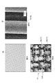
- FIG. 3A is an enlarged image of the composite fabric
- FIG. 3A is a composite fabric according to Example 1
- FIG. 3B is a composite fabric according to Comparative Example 1.
- FIG. 4A is an enlarged image of a carbon fiber bundle
- FIG. 4B is an enlarged image of a carbon fiber.
- FIG. 4A is a scanning electron microscope (SEM) image of the composite fabric according to Example 1.
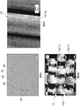
- FIG. 5A and 5B are diagrams for explaining Example 2, in which FIG.
- FIG. 5A is an enlarged image of a dispersion liquid in which CNTs are isolated and dispersed
- FIG. 5B is an enlarged image of a composite fabric
- FIG. 5C is an SEM image of a carbon fiber bundle
- FIG. 6A is an enlarged view of a dispersion liquid in which aggregates of CNTs are mixed
- FIG. 6B is an enlarged image of a composite fabric
- FIG. 6C is an SEM image of a carbon fiber bundle.
- FIG. 7A is a composite fabric according to Example 4
- FIG. 7B is a composite fabric according to Example 5
- FIG. 7C is a composite fabric according to Example 6
- FIG. 7D is a composite according to Example 7.
- the fabric, FIG. 7E is a composite fabric according to Comparative Example 2.
- FIG. 11A is an SEM image of a carbon fiber bundle obtained by a method for manufacturing a composite fabric according to a modification
- FIG. 11A is one end which is the outermost side of a laminate wound in a roll shape
- FIG. 11B is an overlapped portion of the laminate
- FIG. 11C shows the other end which is the innermost side.
- the composite fabric 10 shown in FIG. 1 includes a woven fabric 12A and structures 14 formed on both surfaces of the woven fabric 12A.
- the woven fabric 12A is a carbon fiber cloth using a carbon fiber bundle 17 in which a plurality of carbon fibers are bundled as a woven yarn.
- the woven fabric 12A shown in this figure is formed by a plain weave with the carbon fiber bundle 17 as warps 18 and wefts 20.
- Carbon fiber is a fiber having a diameter of about 5 to 20 ⁇ m obtained by firing organic fiber derived from petroleum such as polyacrylonitrile, rayon and pitch, coal, coal tar, organic fiber derived from wood or plant fiber. .
- the structure 14 includes a plurality of CNTs 16 that are evenly distributed over the entire surface of the woven fabric 12A.
- the structure 14 has a network structure part in which a plurality of CNTs 16 are directly connected to each other.
- the direct connection means that the CNTs 16 are not covered with a dispersant, a surfactant, an adhesive, or the like and are intertwined with each other, and the adhesive, the dispersant, the surfactant, etc. are between the CNTs 16. This means that the connection is made without going through any inclusions, and includes physical connection (simple contact) and chemical connection.
- the CNT 16 is preferably a multilayer. Moreover, it is preferable that CNT16 is 0.1 micrometer or more and 50 micrometers or less in length. If the length of the CNTs 16 is 0.1 ⁇ m or more, the CNTs 16 are entangled and directly connected. Further, when the length of the CNT 16 is 50 ⁇ m or less, it becomes easy to disperse evenly. On the other hand, if the length of the CNT 16 is less than 0.1 ⁇ m, the CNTs 16 are less likely to be entangled with each other. Further, when the length of the CNT 16 exceeds 50 ⁇ m, the CNT 16 tends to aggregate.
- CNT16 preferably has a diameter of 30 nm or less.
- the diameter of the CNT 16 is 30 nm or less, the CNT 16 is rich in flexibility and deforms along the curved surface of the surface of the carbon fiber.
- the diameter of the CNT 16 is more than 30 nm, the flexibility becomes poor and it is difficult to deform along the surface of the carbon fiber.
- the diameter of CNT16 is more preferably 20 nm or less.
- the diameter of the CNT 16 was taken by a transmission electron microscope (TEM) before taking out a part of the CNT 16 used for attachment before attaching the CNT 16 to the carbon fiber by the method described below. The average diameter measured using the image.
- TEM transmission electron microscope
- Such a structure 14 is directly fixed to the surface of the woven fabric 12A. That is, the CNT 16 is not fixed to the surface of the carbon fiber by being covered with an adhesive, a dispersant, a surfactant, or the like together with the surface of the carbon fiber, but via an adhesive, a dispersant, a surfactant, or the like. Instead of being fixed to the carbon fiber, it is directly fixed to the surface of the carbon fiber.
- the term “fixation” as used herein includes bonding of carbon fiber and CNT 16 by van der Waals force, and chemical bonding of carbon fiber and CNT 16 via a hydroxy group or a carboxy group formed on the surface of CNT 16. .
- the structure 14 may include an agglomerated part (not shown in the drawing) in which a plurality of CNTs 16 are aggregated.
- the agglomerated part here means a state in which two or more CNTs 16 are physically intertwined.
- the abundance ratio of aggregated portions in the woven fabric is 25% or less per unit area.
- the composite fabric 10 can be applied to a CFRTP (Carbon Fiber Reinforced Thermoplastics) material as a carbon fiber reinforced molded body by impregnating a thermoplastic resin as a base material, for example.
- CFRTP Carbon Fiber Reinforced Thermoplastics
- the composite fabric 10 can be manufactured by preparing the CNTs 16, adjusting the dispersion containing the CNTs 16, and forming the structure 14 on the surface of the woven fabric 12 A using the dispersion. Hereinafter, each process is demonstrated in order.
- the CNT 16 can be manufactured using a thermal CVD method as described in, for example, Japanese Patent Application Laid-Open No. 2007-12611. In this case, first, a catalyst film made of aluminum and iron is formed on a silicon substrate, and the catalyst film is heat-treated to form catalyst particles on the surface of the catalyst film. Next, CNT16 can be produced by bringing hydrocarbon gas into contact with the catalyst particles in a heated atmosphere and growing CNT16 from the catalyst particles.
- the CNTs 16 thus produced are linearly oriented in the direction perpendicular to the substrate surface on the substrate and have a high aspect ratio of several hundred to several thousand.
- the CNT 16 is used by cutting from the substrate.
- the cut CNT 16 may contain catalyst residues such as catalyst particles and fragments thereof.
- the catalyst residue is desirably removed by annealing the produced CNT 16 at a high temperature in an inert gas or by acid treatment.
- CNT16 can also be obtained by other production methods such as an arc discharge method and a laser evaporation method, it is desirable to produce CNT16 by a method that does not contain impurities (such as catalyst residues) other than CNT16 as much as possible. It is desirable to remove this impurity as well as the catalyst residue.
- impurities such as catalyst residues
- a dispersion liquid in which the CNT 16 produced by the above method is isolated and dispersed is prepared.
- the isolated dispersion means that the CNTs 16 are dispersed in the dispersion solvent in a state where the CNTs 16 are not physically separated and entangled one by one, and the ratio of the aggregate in which two or more CNTs 16 are gathered in a bundle is 10% or less. It means a certain state.
- the ratio of the aggregate in which the CNTs 16 are aggregated is obtained by measuring the number of the CNTs 16 and the number of the aggregates from the TEM image.
- the CNT 16 produced by the above method is oxidized in an oxygen atmosphere at a predetermined temperature.
- a functional group such as a hydroxy group or a carboxy group is formed on the surface of the CNT 16 on a part of the surface of the CNT 16.
- the CNT 16 may be oxidized using an ozone treatment device, for example, a mixed acid of nitric acid and sulfuric acid (the ratio can be arbitrarily determined), or a hydrogen peroxide-sulfuric acid sulfuric acid persulfate (the ratio is arbitrarily determined).
- CNT16 may be immersed in the substrate and oxidized.
- the CNT 16 whose surface is oxidized is put into a dispersion solvent so as to have a predetermined mass concentration, and the CNT 16 is isolated and dispersed by uniformly dispersing the CNT 16 with a homogenizer, high-pressure shear, an ultrasonic disperser or the like. Dispersion can be produced.
- Dispersion solvents include water, alcohols (ethanol, methanol, isopropyl alcohol, etc.), organic solvents (toluene, acetone, tetrahydrofuran (THF), methyl ethyl ketone (MEK), hexane, normal hexane, ethyl ether, xylene, methyl acetate, acetic acid. Ethyl) and the like.
- the dispersion may contain a dispersant, a surfactant, an adhesive, and the like as long as the functions of the woven fabric 12A and the CNT 16 are not limited.
- the dispersion is not limited to the case where the above-mentioned aggregate ratio is 10% or less, and preferably contains a certain amount of isolated and dispersed CNT16.
- a woven fabric 12A, a filter part 22A, and a holding part 24, which are cut into a predetermined size, are prepared.
- the woven fabric 12A is a carbon fiber cloth, and a sizing agent is applied to the surface.
- the filter part 22A can use a mesh formed of a synthetic resin.
- the synthetic resin is sufficient if it has resistance to the dispersion solvent, and can be selected from, for example, polypropylene, polyethylene, polyamide, polyester, and the like.
- the mesh opening of the filter portion 22A is preferably 840 ⁇ m or less, and more preferably 41 ⁇ m or less.
- the mesh size is represented by (25.4 / Md), where M is the number of meshes between 1 inch (25.4 mm) of the vertical and horizontal lines, and d is the wire diameter.
- the holding part 24 can use a wire mesh.
- the holding part 24 has an opening (about 0.6 mm) through which ultrasonic waves can pass, and the center of the surface is curved and protrudes in the thickness direction.
- the laminated body 25 is obtained by arranging the filter portion 22A and the holding portion 24 in this order on both sides of the woven fabric 12A.
- the holding part 24 is arranged so that the curved and protruding surface is in contact with the filter part 22A.
- the laminated body 25 is integrated by sandwiching the end portions of the holding portion 24 with a clip (not shown). Thereby, the filter part 22A is pressed against the surface of the woven fabric 12A by the holding part 24.
- the gap between the woven fabric 12A and the filter portion 22A is preferably 100 ⁇ m or less.
- the laminate 25 is immersed in a resin remover to remove the sizing agent applied to the surface of the woven fabric 12A.
- a resin remover for example, an organic solvent such as MEK can be used as the resin remover.
- MEK organic solvent
- the sizing agent is removed, the carbon fiber bundles 17 are unbound, but the woven fabric 12A is held in a plain weave state by being fixed by the holding portion 24.
- the laminate 25 is immersed in the dispersion liquid prepared as described above, and ultrasonic vibration is applied to the dispersion liquid.
- ultrasonic vibration is applied to the dispersion, a reversible reaction state in which the CNT 16 is dispersed and aggregated is repeated in the dispersion. This reversible reaction state also occurs while the laminate 25 is immersed in the dispersion.
- the ultrasonic vibration passes through the holding unit 24 and the filter unit 22A and reaches the woven fabric 12A.
- the isolated and dispersed CNT 16 passes through the holding unit 24 and the filter unit 22A by this ultrasonic vibration and reaches the woven fabric 12A.
- a structure 14 is formed on the carbon fiber.
- the CNTs 16 When the CNTs 16 are aggregated, the CNTs 16 are fixed to the surface of the carbon fiber via a hydroxy group or a carboxy group formed on the surface of the CNT 16 or van der Waals force acting between the carbon fiber and the CNT 16.
- the aggregate contained in the dispersion cannot pass through the filter portion 22A and does not reach the woven fabric 12A. Therefore, although the aggregate of CNTs adheres to the filter part 22A, it is prevented from adhering to the surface of the woven fabric 12A by being blocked by the filter part 22A.
- the gap between the woven fabric 12A and the filter portion 22A is maintained at 100 ⁇ m or less, no flow such as convection of the dispersion occurs on the surface of the woven fabric 12A, and the CNTs 16 are only in the dispersion by ultrasonic vibration. Moving. This prevents the CNTs 16 once attached to the woven fabric 12A from being peeled off by the flow of the dispersion liquid, so that the attached amount of the CNTs 16 increases dramatically.
- the laminate 25 is taken out from the dispersion, washed with MEK, the clip is removed, and the filter portion 22A and the holding portion 24 are removed from the woven fabric 12A.
- the laminate 25 is dried.
- the composite fabric 10 including the woven fabric 12A on which the structure 14 is formed can be obtained.
- the structure 14 is not formed because the CNTs 16 do not enter between the carbon fiber bundles 17 in the weave of the woven fabric 12, that is, the portions where the carbon fiber bundles 17 overlap each other.
- the laminate 25 may be taken out of the dispersion, and the clip may be immediately removed to remove the filter portion 22A and the holding portion 24 from the woven fabric 12A, and then washed with MEK.
- the composite fabric 10 according to the present embodiment has the CNT 16 formed by ultrasonic vibration in the dispersion liquid with the filter portion 22A provided on the surface of the woven fabric 12A so that the gap is 100 ⁇ m or less.
- the structure 14 is formed on the surface of the woven fabric 12A by being attached, and is manufactured. Aggregates of CNTs adhering to the filter unit 22A become dried CNT aggregates on the filter unit 22A and are removed together with the filter unit 22A.
- the composite fabric 10 having the structure 14 including the CNTs 16 on the surface has fine unevenness caused by the structure 14 on the surface. Therefore, the adhesive force between the composite fabric 10 and the base material is enhanced by the anchor effect.
- a base material made of a cured resin material has a low elastic modulus.
- a composite layer is formed by a part of the base material and the CNTs 16 at the interface between the woven fabric and the base material.
- the composite layer interposed between the woven fabric 12A and the base material alleviates stress concentration at the interface between the woven fabric 12A and the base material by suppressing a sudden change in elastic modulus, and the strength of the carbon fiber reinforced molded body. Can be improved.
- the stress since the stress is concentrated in the agglomerated portion included in the structure, it causes a decrease in the strength of the carbon fiber reinforced molded body.
- the composite fabric 10 can form the structure 14 with few agglomerated parts of the CNTs 16 on the surface of the woven fabric 12A. Thereby, the composite fabric 10 can improve the strength of the carbon fiber reinforced molded body. Therefore, since the carbon fiber reinforced molded body using the composite fabric 10 can obtain a uniform composite layer, the strength can be further improved. Moreover, since the composite fabric 10 has few CNT16 aggregation parts on the surface, the design of the surface of the carbon fiber reinforced molded body using the composite fabric 10 can be improved.
- the composite fabric 10 according to Example 1 was manufactured according to the procedure shown in the above “(2) Manufacturing Method”.
- Example 1 as the CNT 16, multi-walled carbon nanotubes grown on a silicon substrate to have a diameter of 10 to 15 nm and a length of 100 ⁇ m or more by the above-described thermal CVD method were used.
- the produced CNT16 is immersed in a mixed acid of nitric acid and sulfuric acid (ratio can be determined arbitrarily) or hydrogen peroxide solution and sulfuric acid / hydrogen peroxide (ratio can be determined arbitrarily), washed and filtered and dried. The catalyst residue was removed.
- the CNT 16 is not separately oxidized.
- the length of the produced CNT16 is as long as 100 ⁇ m or more, after the CNT16 is put into MEK as a dispersion solvent, the CNT16 is crushed with an ultrasonic homogenizer until the CNT16 becomes 0.5 to 10 ⁇ m in length. Evenly dispersed.
- the concentration of CNT 16 in the dispersion was 0.025 wt%.
- Carbon fiber fabric (made by Sakai Obex, model (product) number: SA-32021, size 50 ⁇ 50 mm) as woven fabric 12A, and nylon mesh (made by NYTAL, model (product) number: NY41-HC, size) as filter section 22A
- a work net (manufactured by Takashi Yoshida, mold (product) number: 2004-45 (T), size 70 ⁇ 70 mm) was used as the holding portion 24.
- the laminate 25 was immersed in a resin remover to remove the sizing agent. MEK was used as the resin remover.
- the laminate 25 was immersed in the dispersion, and 130 kHz ultrasonic waves were continuously applied to the dispersion for 1 minute 30 seconds.
- a composite fabric 10 was obtained.
- a composite fabric 10 according to Comparative Example 1 was produced under the same conditions as in Example 1 except that the filter part 22A and the holding part 24 were not used.
- the CNTs 16 are uniformly attached to the surface of the carbon fibers 21, and the carbon fibers 21 constituting the carbon fiber bundle 17 are connected to each other by the CNTs 16. It was confirmed.
- Example 2 The composite fabric 10 according to Example 2 was produced under the same conditions as in Example 1.
- the composite fabric 10 according to Example 2 was produced under the same conditions as in Example 1 except that the solvent of the dispersion was changed to ethanol.
- the results of Example 2 are shown in FIGS. 5A to 5C, and the results of Example 3 are shown in FIGS. 6A to 6C.
- FIG. 5A since the CNT 16 was completely isolated and dispersed in the dispersion liquid 26 used in Example 2, no aggregate was confirmed.
- FIG. 5A since the CNT 16 was completely isolated and dispersed in the dispersion liquid 26 used in Example 2, no aggregate was confirmed.
- FIG. 5A since the CNT 16 was completely isolated and dispersed in the dispersion liquid 26 used in Example 2, no aggregate was confirmed.
- FIG. 5A since the CNT 16 was completely isolated and dispersed in the dispersion liquid 26 used in Example 2, no aggregate was confirmed.
- FIG. 5A since the CNT 16 was completely isolated and dispersed in the dispersion liquid 26 used
- Example 6A in the dispersion liquid 28 used in Example 3, a plurality of aggregates 29 of CNTs 16 were observed. However, not only in Example 2, but also in the composite fabric 10 according to Example 3, almost no agglomerated portion is observed on the surface of the woven fabric 12A, and the CNTs 16 are uniformly attached to the surface of the carbon fiber 21, and the difference between the two. The result that there was no. From this, by using the manufacturing method according to the present embodiment, the filter portion 22A prevents the aggregate 29 of the CNTs 16 included in the dispersion from adhering to the woven fabric 12A, thereby including aggregates. It could be confirmed that the composite fabric 10 having few aggregated portions can be obtained even with the dispersion.
- the filter part 22A of Example 4 is made of NYTAL (model (product) number: NY10-HC, opening 10 ⁇ m)
- the filter part 22A of Example 5 is made of NYTAL (model (product) number: NY20-HC, opening 20 ⁇ m).
- the filter part 22A of Example 6 is manufactured by NYTAL (type (product) number: NY41-HC, opening 41 ⁇ m)
- the filter part 22A of Example 7 is manufactured by DIO Kasei Co., Ltd.
- Comparative Example 2 (model number: DIO CROWN NET, opening) 840 ⁇ m) was used.
- a composite fabric 10 of Comparative Example 2 was produced under the same conditions as in Example 1 except that the filter part 22A and the holding part 24 were not used. The results are shown in FIGS. 7A to 7E.
- Comparative Example 2 that does not use the filter portion 22A, a large number of island-like aggregated portions 101 were observed (FIG. 7E), whereas, as shown in FIG. 7D, the filter portion 22A having an aperture of 840 ⁇ m was used for aggregation. It was confirmed that the portion 101 was small and punctiform and the number decreased. From this, it was confirmed that by using the filter portion 22A having an opening of 840 ⁇ m or less, the composite fabric 10 with few aggregated portions 101 can be produced.
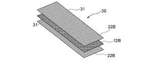
- the filter unit 22B is disposed on both sides of the woven fabric 12B, and the laminate 30 is obtained.
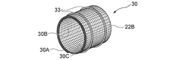
- the other end 30C of the laminate 30 is rounded toward the one end 30A.
- the laminated body 30 is held in a rubber band 33 while being wound in a roll shape (FIG. 10).
- a spacer may be provided at each of the edge portions (FIG. 8) 31 parallel to the longitudinal direction of the filter portion 22A disposed inside.
- the dispersion liquid easily penetrates between the stacked bodies 30 by providing a gap in a portion where the stacked bodies 30 overlap each other when wound in a roll shape.
- the spacer is an elastically deformable resin member and is preferably provided over the entire length of the filter portion 22B.
- the composite fabric 10 in which the structure 14 is formed on the surface of the woven fabric 12B by immersing the laminate 30 in the dispersion and applying ultrasonic vibration to the dispersion as in the above embodiment. Can be obtained. Since the filter unit 22B blocks the aggregate of the CNTs 16 in the dispersion liquid and the aggregate does not reach the woven fabric 12B, the same effect as in the above embodiment can be obtained.
- the gap between the woven fabric 12B and the filter portion 22B can be reduced to 100 ⁇ m or less by holding the laminated body 30 in a roll shape, so the holding portion 24 is omitted. be able to.
- the filter portions 22B are arranged on both sides of the woven fabric 12B.
- the present invention is not limited to this, and the filter portion 22B arranged on the inner side when rolled up is omitted. Also good.
- a composite fabric 10 according to Example 8 was produced according to the manufacturing method according to this modification.
- Carbon fiber fabric made by Sakai Obex, mold (product) number: SA-32021, size 50 ⁇ 400 mm
- woven fabric 12B As woven fabric 12B, and manufactured by Dio Kasei Co., Ltd. (model number: Dio Crown Net, size 70 ⁇ 450 mm)
- a composite fabric 10 was produced under the same conditions as in Example 1 except that was used.
- the laminated body 30 was wound in roll shape so that an outer diameter might be set to 55 mm.
Landscapes
- Engineering & Computer Science (AREA)
- Textile Engineering (AREA)
- Physics & Mathematics (AREA)
- Plasma & Fusion (AREA)
- Mechanical Engineering (AREA)
- Woven Fabrics (AREA)
- Chemical Or Physical Treatment Of Fibers (AREA)
Abstract
Description
図1に示す複合織物10は、織布12Aと、当該織布12Aの両面に形成された構造体14とを備える。織布12Aは、複数の炭素繊維を束ねた炭素繊維束17を織糸とする炭素繊維クロスである。本図に示す織布12Aは、炭素繊維束17を経糸18及び緯糸20とした平織りで形成されている。炭素繊維は、ポリアクリルニトリル、レーヨン、ピッチなどの石油、石炭、コールタール由来の有機繊維、木材や植物繊維由来の有機繊維を焼成することによって得られる、直径が約5~20μmの繊維である。
次に、本実施形態に係る複合織物10の製造方法を説明する。複合織物10は、CNT16を作製し、当該CNT16を含む分散液を調整し、当該分散液を用いて構造体14を織布12A表面に形成することにより製造することができる。以下、各工程について順に説明する。
CNT16は、例えば特開2007-126311号公報に記載されているような熱CVD法を用いて作製することができる。この場合、まず、シリコン基板上にアルミ、鉄からなる触媒膜を成膜し、触媒膜を熱処理して触媒膜表面に触媒粒子を形成する。次に、加熱雰囲気中で炭化水素ガスを触媒粒子に接触させて触媒粒子からCNT16を成長させることで、CNT16を作製できる。
上記の方法で作製したCNT16が単離分散した分散液を調整する。単離分散とは、CNT16が1本ずつ物理的に分離して絡み合っていない状態で分散溶媒中に分散しており、2以上のCNT16が束状に集合した集合物の割合が10%以下である状態を意味する。CNT16が凝集した集合物の割合は、TEM画像からCNT16の本数と集合物の個数を測定して求める。
図2に示すように、所定の大きさに切断した、織布12Aと、フィルタ部22Aと、保持部24とを準備する。織布12Aは、炭素繊維クロスであり、表面にサイズ剤が塗布されている。フィルタ部22Aは、合成樹脂で形成されたメッシュを用いることができる。合成樹脂は、上記分散溶媒に対し耐性を有していれば足り、例えば、ポリプロピレン、ポリエチレン、ポリアミド、ポリエステル等から選択することができる。フィルタ部22Aとしてのメッシュの目開きは、840μm以下が好ましく、より好ましくは41μm以下である。なお目開きは、縦線及び横線の1インチ(25.4mm)間による目数をM、線径をdとすると、(25.4/M-d)で表される。保持部24は、金網を用いることができる。保持部24は、超音波が通過し得る目開き(0.6mm程度)を有しており、表面の中央が、厚さ方向に湾曲して突出している。
本実施形態に係る複合織物10は、織布12Aの表面に隙間が100μm以下となるようにフィルタ部22Aを設けた状態で、分散液中で超音波振動により、CNT16を付着させ織布12Aの表面に構造体14を形成して、作製することとした。フィルタ部22Aに付着したCNTの集合物は、フィルタ部22A上で乾燥後CNTの凝集部となって、フィルタ部22Aと共に取り除かれる。
本発明は上記実施形態に限定されるものではなく、本発明の趣旨の範囲内で適宜変更することが可能である。
12A、12B 織布
14 構造体
17 炭素繊維束
18 経糸(織糸)
20 緯糸(織糸)
22A、22B フィルタ部
24 保持部
Claims (6)
- 分散溶媒と当該分散溶媒中に分散したカーボンナノチューブとを通過させるフィルタ部の表面を、炭素繊維束を織糸とする織布の少なくとも1表面に接触させて保持する工程と、
前記分散溶媒と前記分散したカーボンナノチューブとを含む分散液中に、前記フィルタ部が保持された前記織布を浸漬し、前記分散液に超音波振動を印加する工程と、
前記分散液から前記フィルタ部が保持された前記織布を取り出し、前記織布から前記フィルタ部を取り外す工程と
を備えることを特徴とする複合織物の製造方法。 - 前記フィルタ部を前記織布に保持する工程は、
前記フィルタ部を、前記織布の両面に設け、前記織布に押し付けた状態で保持する
ことを特徴とする請求項1記載の複合織物の製造方法。 - 前記フィルタ部は、表面が厚さ方向に湾曲して突出した保持部によって、前記織布に押し付けた状態で保持されていることを特徴とする請求項2記載の複合織物の製造方法。
- 前記フィルタ部を前記織布に保持する工程は、
前記フィルタ部が外側となるように前記織布をロール状に巻いた状態で保持する
ことを特徴とする請求項1記載の複合織物の製造方法。 - 炭素繊維束を織糸とする織布と、
前記織布の表面に形成され、複数のカーボンナノチューブを含む構造体と
を備え、
前記構造体は、
前記複数のカーボンナノチューブが互いに直接接続されたネットワーク構造部を含み、前記複数のカーボンナノチューブが凝集した凝集部の存在比率が単位面積あたり25%以下であることを特徴とする複合織物。 - 請求項5記載の複合織物を備えることを特徴とする炭素繊維強化成形体。
Priority Applications (4)
| Application Number | Priority Date | Filing Date | Title |
|---|---|---|---|
| EP17770246.1A EP3434823B1 (en) | 2016-03-25 | 2017-03-22 | Method for manufacturing a composite fabric |
| KR1020187030432A KR20180121655A (ko) | 2016-03-25 | 2017-03-22 | 복합 직물의 제조 방법, 복합 직물 및 탄소 섬유 강화 성형체 |
| CN201780012218.0A CN108884628B (zh) | 2016-03-25 | 2017-03-22 | 复合织物的制造方法、复合织物及碳纤维增强成形体 |
| US16/079,257 US10689797B2 (en) | 2016-03-25 | 2017-03-22 | Method for manufacturing composite fabric, composite fabric, and carbon fiber reinforced molding |
Applications Claiming Priority (2)
| Application Number | Priority Date | Filing Date | Title |
|---|---|---|---|
| JP2016062113A JP6703427B2 (ja) | 2016-03-25 | 2016-03-25 | 複合織物の製造方法 |
| JP2016-062113 | 2016-03-25 |
Publications (1)
| Publication Number | Publication Date |
|---|---|
| WO2017164206A1 true WO2017164206A1 (ja) | 2017-09-28 |
Family
ID=59899442
Family Applications (1)
| Application Number | Title | Priority Date | Filing Date |
|---|---|---|---|
| PCT/JP2017/011336 Ceased WO2017164206A1 (ja) | 2016-03-25 | 2017-03-22 | 複合織物の製造方法、複合織物及び炭素繊維強化成形体 |
Country Status (6)
| Country | Link |
|---|---|
| US (1) | US10689797B2 (ja) |
| EP (1) | EP3434823B1 (ja) |
| JP (1) | JP6703427B2 (ja) |
| KR (1) | KR20180121655A (ja) |
| CN (1) | CN108884628B (ja) |
| WO (1) | WO2017164206A1 (ja) |
Cited By (1)
| Publication number | Priority date | Publication date | Assignee | Title |
|---|---|---|---|---|
| CN111201343A (zh) * | 2017-10-13 | 2020-05-26 | 国立研究开发法人产业技术综合研究所 | 由碳纳米管构成的纤维和其制造方法 |
Families Citing this family (6)
| Publication number | Priority date | Publication date | Assignee | Title |
|---|---|---|---|---|
| TWI660800B (zh) * | 2018-02-14 | 2019-06-01 | 黃振正 | Multi-layer thin composite cloth |
| JP6608086B2 (ja) * | 2018-03-16 | 2019-11-20 | 株式会社アプリコ | 袋体開口装置 |
| EP3819424A4 (en) * | 2018-06-11 | 2022-05-11 | Nitta Corporation | COMPOSITE MATERIAL, PREPREG, CARBON FIBER REINFORCED MOLDED PRODUCT AND METHOD FOR PRODUCING THE COMPOSITE MATERIAL |
| KR102203637B1 (ko) * | 2019-05-14 | 2021-01-18 | 세방전지(주) | 저 전도성 직물시트를 이용한 전극용 활성탄 시트의 제조 방법 |
| WO2021100859A1 (ja) * | 2019-11-20 | 2021-05-27 | ニッタ株式会社 | 複合素材及びその製造方法 |
| JP7406959B2 (ja) * | 2019-11-20 | 2023-12-28 | ニッタ株式会社 | 複合素材、炭素繊維強化成形体及び複合素材の製造方法 |
Citations (3)
| Publication number | Priority date | Publication date | Assignee | Title |
|---|---|---|---|---|
| JP2009535530A (ja) * | 2006-05-02 | 2009-10-01 | ロール インコーポレイテッド | ナノ補強材を用いた複合材料中に用いられる補強繊維トウの修飾 |
| JP2013509503A (ja) * | 2009-11-02 | 2013-03-14 | アプライド ナノストラクチャード ソリューションズ リミテッド ライアビリティー カンパニー | Cnt浸出炭素繊維材料及びその製造プロセス |
| JP2013076198A (ja) * | 2011-09-13 | 2013-04-25 | Nitta Ind Corp | Cnt/炭素繊維複合素材、この複合素材を用いた繊維強化成形品、および複合素材の製造方法 |
Family Cites Families (9)
| Publication number | Priority date | Publication date | Assignee | Title |
|---|---|---|---|---|
| JP4273092B2 (ja) * | 2005-03-30 | 2009-06-03 | 株式会社Gsiクレオス | プリプレグの製造方法およびプリプレグの製造装置 |
| JP5057010B2 (ja) | 2005-11-01 | 2012-10-24 | ニッタ株式会社 | カーボンファイバの製造方法 |
| US7867468B1 (en) * | 2008-02-28 | 2011-01-11 | Carbon Solutions, Inc. | Multiscale carbon nanotube-fiber reinforcements for composites |
| KR101265847B1 (ko) * | 2008-12-22 | 2013-05-20 | 도요타지도샤가부시키가이샤 | 복합형 탄소 및 그 제조방법 |
| CN101700705B (zh) * | 2009-06-08 | 2013-07-10 | 电子科技大学 | 一种热固性树脂玻纤层压复合材料及其制备方法 |
| US9107292B2 (en) * | 2012-12-04 | 2015-08-11 | Applied Nanostructured Solutions, Llc | Carbon nanostructure-coated fibers of low areal weight and methods for producing the same |
| CN103396656A (zh) * | 2013-08-27 | 2013-11-20 | 连云港神鹰碳纤维自行车有限责任公司 | 一种纳米改性碳纤维预浸料用环氧树脂体系的制备方法 |
| CN104327454B (zh) | 2014-10-11 | 2016-07-06 | 沈阳航空航天大学 | 一种碳纳米管/连续纤维混杂增强复合材料的制备方法 |
| JP6875047B2 (ja) * | 2016-01-14 | 2021-05-19 | ニッタ株式会社 | バイオ燃料電池用電極及びバイオ燃料電池 |
-
2016
- 2016-03-25 JP JP2016062113A patent/JP6703427B2/ja active Active
-
2017
- 2017-03-22 US US16/079,257 patent/US10689797B2/en active Active
- 2017-03-22 CN CN201780012218.0A patent/CN108884628B/zh active Active
- 2017-03-22 WO PCT/JP2017/011336 patent/WO2017164206A1/ja not_active Ceased
- 2017-03-22 EP EP17770246.1A patent/EP3434823B1/en active Active
- 2017-03-22 KR KR1020187030432A patent/KR20180121655A/ko not_active Withdrawn
Patent Citations (3)
| Publication number | Priority date | Publication date | Assignee | Title |
|---|---|---|---|---|
| JP2009535530A (ja) * | 2006-05-02 | 2009-10-01 | ロール インコーポレイテッド | ナノ補強材を用いた複合材料中に用いられる補強繊維トウの修飾 |
| JP2013509503A (ja) * | 2009-11-02 | 2013-03-14 | アプライド ナノストラクチャード ソリューションズ リミテッド ライアビリティー カンパニー | Cnt浸出炭素繊維材料及びその製造プロセス |
| JP2013076198A (ja) * | 2011-09-13 | 2013-04-25 | Nitta Ind Corp | Cnt/炭素繊維複合素材、この複合素材を用いた繊維強化成形品、および複合素材の製造方法 |
Non-Patent Citations (1)
| Title |
|---|
| See also references of EP3434823A4 * |
Cited By (3)
| Publication number | Priority date | Publication date | Assignee | Title |
|---|---|---|---|---|
| CN111201343A (zh) * | 2017-10-13 | 2020-05-26 | 国立研究开发法人产业技术综合研究所 | 由碳纳米管构成的纤维和其制造方法 |
| EP3696303A4 (en) * | 2017-10-13 | 2021-04-07 | National Institute Of Advanced Industrial Science | CARBON NANOTUBE FIBER AND METHOD FOR MANUFACTURING IT |
| US11686019B2 (en) | 2017-10-13 | 2023-06-27 | National Institute Of Advanced Industrial Science And Technology | Fiber constituted from carbon nanotube and method for manufacturing same |
Also Published As
| Publication number | Publication date |
|---|---|
| EP3434823B1 (en) | 2021-05-12 |
| EP3434823A1 (en) | 2019-01-30 |
| EP3434823A4 (en) | 2019-12-04 |
| JP2017172088A (ja) | 2017-09-28 |
| KR20180121655A (ko) | 2018-11-07 |
| US20190048519A1 (en) | 2019-02-14 |
| CN108884628B (zh) | 2021-03-26 |
| CN108884628A (zh) | 2018-11-23 |
| US10689797B2 (en) | 2020-06-23 |
| JP6703427B2 (ja) | 2020-06-03 |
Similar Documents
| Publication | Publication Date | Title |
|---|---|---|
| JP6703427B2 (ja) | 複合織物の製造方法 | |
| JP6521701B2 (ja) | 複合素材の製造方法 | |
| KR102453189B1 (ko) | 복합 소재 및 강화 섬유 | |
| KR100564774B1 (ko) | 나노복합체 섬유, 그 제조방법 및 용도 | |
| JP7256502B2 (ja) | シート及びその製造方法 | |
| WO2012086682A1 (ja) | 炭素繊維集合体の製造方法および炭素繊維強化プラスチックの製造方法 | |
| CN104822622A (zh) | 制造碳纳米结构涂布的纤维的方法 | |
| CN102598875A (zh) | 碳-碳复合材料中的并入cnt的纤维 | |
| EP3690133B1 (en) | Composite material, prepreg, carbon-fiber-reinforced molded body, and method for manufacturing composite material | |
| US20070144780A1 (en) | Field emission element and method for manufacturing same | |
| JPWO2015146984A1 (ja) | 導電性多孔体、固体高分子形燃料電池、及び導電性多孔体の製造方法 | |
| US10934637B2 (en) | Process for producing fabric of continuous graphene fiber yarns from functionalized graphene sheets | |
| JP2007070593A (ja) | プリプレグ及びその製造方法,炭素繊維並びに繊維体 | |
| JP7737899B2 (ja) | カーボンナノチューブ-樹脂複合体及びカーボンナノチューブ-樹脂複合体の製造方法 | |
| CN114729500B (zh) | 复合材料、碳纤维增强成型体以及复合材料的制造方法 | |
| US20190352805A1 (en) | Fabric of continuous graphene fiber yarns from functionalized graphene sheets | |
| JP6208510B2 (ja) | 複合素材の製造方法 | |
| US11898305B2 (en) | Composite material, and prepreg using same | |
| KR102898017B1 (ko) | 탄소나노섬유 및 이의 제조 방법 | |
| JP6520621B2 (ja) | Cnt構造体の製造方法および製造装置 | |
| TWI448416B (zh) | 線熱源的製備方法 | |
| JP2012162812A (ja) | 糸状カーボンナノ構造物の製造方法 |
Legal Events
| Date | Code | Title | Description |
|---|---|---|---|
| NENP | Non-entry into the national phase |
Ref country code: DE |
|
| ENP | Entry into the national phase |
Ref document number: 20187030432 Country of ref document: KR Kind code of ref document: A |
|
| WWE | Wipo information: entry into national phase |
Ref document number: 2017770246 Country of ref document: EP |
|
| ENP | Entry into the national phase |
Ref document number: 2017770246 Country of ref document: EP Effective date: 20181025 |
|
| 121 | Ep: the epo has been informed by wipo that ep was designated in this application |
Ref document number: 17770246 Country of ref document: EP Kind code of ref document: A1 |