WO2017164209A1 - 積層透明導電膜、積層配線膜及び積層配線膜の製造方法 - Google Patents
積層透明導電膜、積層配線膜及び積層配線膜の製造方法 Download PDFInfo
- Publication number
- WO2017164209A1 WO2017164209A1 PCT/JP2017/011343 JP2017011343W WO2017164209A1 WO 2017164209 A1 WO2017164209 A1 WO 2017164209A1 JP 2017011343 W JP2017011343 W JP 2017011343W WO 2017164209 A1 WO2017164209 A1 WO 2017164209A1
- Authority
- WO
- WIPO (PCT)
- Prior art keywords
- film
- transparent conductive
- atomic
- laminated
- conductive oxide
- Prior art date
- Legal status (The legal status is an assumption and is not a legal conclusion. Google has not performed a legal analysis and makes no representation as to the accuracy of the status listed.)
- Ceased
Links
Images


Classifications
-
- H—ELECTRICITY
- H01—ELECTRIC ELEMENTS
- H01B—CABLES; CONDUCTORS; INSULATORS; SELECTION OF MATERIALS FOR THEIR CONDUCTIVE, INSULATING OR DIELECTRIC PROPERTIES
- H01B5/00—Non-insulated conductors or conductive bodies characterised by their form
- H01B5/14—Non-insulated conductors or conductive bodies characterised by their form comprising conductive layers or films on insulating-supports
-
- B—PERFORMING OPERATIONS; TRANSPORTING
- B32—LAYERED PRODUCTS
- B32B—LAYERED PRODUCTS, i.e. PRODUCTS BUILT-UP OF STRATA OF FLAT OR NON-FLAT, e.g. CELLULAR OR HONEYCOMB, FORM
- B32B15/00—Layered products comprising a layer of metal
- B32B15/01—Layered products comprising a layer of metal all layers being exclusively metallic
-
- C—CHEMISTRY; METALLURGY
- C01—INORGANIC CHEMISTRY
- C01G—COMPOUNDS CONTAINING METALS NOT COVERED BY SUBCLASSES C01D OR C01F
- C01G23/00—Compounds of titanium
-
- C—CHEMISTRY; METALLURGY
- C04—CEMENTS; CONCRETE; ARTIFICIAL STONE; CERAMICS; REFRACTORIES
- C04B—LIME, MAGNESIA; SLAG; CEMENTS; COMPOSITIONS THEREOF, e.g. MORTARS, CONCRETE OR LIKE BUILDING MATERIALS; ARTIFICIAL STONE; CERAMICS; REFRACTORIES; TREATMENT OF NATURAL STONE
- C04B35/00—Shaped ceramic products characterised by their composition; Ceramics compositions; Processing powders of inorganic compounds preparatory to the manufacturing of ceramic products
- C04B35/01—Shaped ceramic products characterised by their composition; Ceramics compositions; Processing powders of inorganic compounds preparatory to the manufacturing of ceramic products based on oxide ceramics
- C04B35/453—Shaped ceramic products characterised by their composition; Ceramics compositions; Processing powders of inorganic compounds preparatory to the manufacturing of ceramic products based on oxide ceramics based on zinc, tin, or bismuth oxides or solid solutions thereof with other oxides, e.g. zincates, stannates or bismuthates
-
- C—CHEMISTRY; METALLURGY
- C23—COATING METALLIC MATERIAL; COATING MATERIAL WITH METALLIC MATERIAL; CHEMICAL SURFACE TREATMENT; DIFFUSION TREATMENT OF METALLIC MATERIAL; COATING BY VACUUM EVAPORATION, BY SPUTTERING, BY ION IMPLANTATION OR BY CHEMICAL VAPOUR DEPOSITION, IN GENERAL; INHIBITING CORROSION OF METALLIC MATERIAL OR INCRUSTATION IN GENERAL
- C23C—COATING METALLIC MATERIAL; COATING MATERIAL WITH METALLIC MATERIAL; SURFACE TREATMENT OF METALLIC MATERIAL BY DIFFUSION INTO THE SURFACE, BY CHEMICAL CONVERSION OR SUBSTITUTION; COATING BY VACUUM EVAPORATION, BY SPUTTERING, BY ION IMPLANTATION OR BY CHEMICAL VAPOUR DEPOSITION, IN GENERAL
- C23C14/00—Coating by vacuum evaporation, by sputtering or by ion implantation of the coating forming material
- C23C14/06—Coating by vacuum evaporation, by sputtering or by ion implantation of the coating forming material characterised by the coating material
- C23C14/08—Oxides
-
- C—CHEMISTRY; METALLURGY
- C23—COATING METALLIC MATERIAL; COATING MATERIAL WITH METALLIC MATERIAL; CHEMICAL SURFACE TREATMENT; DIFFUSION TREATMENT OF METALLIC MATERIAL; COATING BY VACUUM EVAPORATION, BY SPUTTERING, BY ION IMPLANTATION OR BY CHEMICAL VAPOUR DEPOSITION, IN GENERAL; INHIBITING CORROSION OF METALLIC MATERIAL OR INCRUSTATION IN GENERAL
- C23C—COATING METALLIC MATERIAL; COATING MATERIAL WITH METALLIC MATERIAL; SURFACE TREATMENT OF METALLIC MATERIAL BY DIFFUSION INTO THE SURFACE, BY CHEMICAL CONVERSION OR SUBSTITUTION; COATING BY VACUUM EVAPORATION, BY SPUTTERING, BY ION IMPLANTATION OR BY CHEMICAL VAPOUR DEPOSITION, IN GENERAL
- C23C14/00—Coating by vacuum evaporation, by sputtering or by ion implantation of the coating forming material
- C23C14/06—Coating by vacuum evaporation, by sputtering or by ion implantation of the coating forming material characterised by the coating material
- C23C14/14—Metallic material, boron or silicon
-
- H—ELECTRICITY
- H01—ELECTRIC ELEMENTS
- H01B—CABLES; CONDUCTORS; INSULATORS; SELECTION OF MATERIALS FOR THEIR CONDUCTIVE, INSULATING OR DIELECTRIC PROPERTIES
- H01B13/00—Apparatus or processes specially adapted for manufacturing conductors or cables
Definitions
- the present invention relates to a laminated transparent conductive film that can be used as a transparent electrode film such as a display or a touch panel, a laminated wiring film comprising the laminated transparent conductive film, and a method for producing the laminated wiring film.
- a laminated transparent conductive film that can be used as a transparent electrode film such as a display or a touch panel
- a laminated wiring film comprising the laminated transparent conductive film
- a method for producing the laminated wiring film is based on Japanese Patent Application No. 2016-058937 filed in Japan on March 23, 2016, and Japanese Patent Application No. 2017-024386 filed in Japan on February 13, 2017. The contents are incorporated herein.
- a transparent conductive film as shown in, for example, Patent Documents 1-4 is provided as a transparent electrode film.
- This transparent conductive film is required to have high light transmittance in the visible light region and low electrical resistance.
- Patent Document 1 an ITO film made of ITO (In 2 O 3 + Sn), which is a kind of transparent conductive oxide, is used as the transparent conductive film.
- ITO film the electrical resistance is lowered.
- the transmittance in the visible light region is lowered. Therefore, it has been difficult to achieve both high transmittance and low electrical resistance.
- Patent Document 2 a metal mesh material such as Cu is used, but in order to reduce the electrical resistance in this metal mesh material, it is necessary to widen the width of the metal portion, and the transmittance is also low. There was a problem of being lowered. In addition, since the metal mesh material may be visually recognized due to light reflection, it is necessary to form a blackened film or the like on the surface of the metal mesh material.
- Patent Documents 3 and 4 propose a laminated transparent conductive film in which an Ag film and a transparent conductive oxide film are laminated.
- this laminated transparent conductive film since the conductivity is ensured by the Ag film, it is not necessary to form a thick transparent conductive oxide film in order to reduce the electrical resistance, and a relatively high transmittance can be obtained. It becomes possible.
- the barrier property against moisture of the transparent conductive oxide film is low, moisture reaches the Ag film in a high humidity environment, Ag aggregation is promoted in the Ag film, and the transmittance and conductivity are reduced. There was a risk of it.
- a wiring pattern is formed on the laminated transparent conductive film.
- a wiring pattern is formed by etching, and then the resist film is removed.
- an electrode pattern is obtained by etching. Since the Ag alloy film has a higher etching rate than that of the ITO film, the overetching of the Ag alloy film becomes large when the same etching solution is used. There was a risk of occurrence.
- the present invention has been made in view of the above-described circumstances, and has a sufficiently high transmittance, a sufficiently low electrical resistance, excellent environmental resistance and alkali resistance, and forms a wiring pattern by an etching method. It is an object of the present invention to provide a laminated transparent conductive film in which over-etching is unlikely to occur, a laminated wiring film composed of the laminated transparent conductive film, and a method for manufacturing the laminated wiring film.
- the laminated transparent conductive film of the present invention has an Ag film made of Ag or an Ag alloy, and a transparent conductive oxide film disposed on both sides of the Ag film, and the transparent conductive film
- the oxide film is formed of an oxide containing Zn, Ga, and Ti.
- the transparent conductive oxide film made of an oxide containing Zn, Ga and Ti is formed on both surfaces of the Ag film, the Ag film is formed by the transparent conductive oxide film on the lower surface.
- the wettability of the Ag film is improved, and aggregation of Ag in the Ag film can be suppressed even when the Ag film is thinly formed.
- the transparent conductive oxide film is excellent in environmental resistance (durability in a high-temperature and high-humidity environment), even when used in a high-humidity environment, the transparent conductive oxide film is formed on the upper surface of the Ag film.
- the formed transparent conductive oxide film can suppress the intrusion of moisture into the Ag film and suppress the aggregation of Ag. Therefore, it is possible to provide a laminated transparent conductive film having a sufficiently high transmittance and a sufficiently low electric resistance.
- an acidic mixed solution containing phosphoric acid and acetic acid is used as an etchant, the difference in etching rate between the Ag film and the transparent conductive oxide film is small, and the accuracy can be obtained even when the laminated transparent conductive film is collectively etched.
- a wiring pattern can be formed well.
- this transparent conductive oxide film has high alkali resistance, even when the resist film is removed using an alkaline resist removing solution when forming a wiring pattern, the deterioration of the characteristics of the laminated transparent conductive film is suppressed. Can do.
- the atomic ratio of all metal elements contained in the transparent conductive oxide film is Ga: 0.5 atomic% to 30.0 atomic%, Ti: 0.1 It is preferable that the atomic percent is not less than 10.0 atomic percent and not more than Zn.
- the Ga content in all the metal elements contained in the transparent conductive oxide film is in the range of 0.5 atomic% to 30 atomic%, the aggregation of the Ag film is suppressed, and the electric resistance Can be suppressed.
- the Ti content is in the range of 0.1 atomic% or more and 10.0 atomic% or less, it is possible to improve alkali resistance and environmental resistance while suppressing an increase in electrical resistance.
- the atomic ratio of all metal elements contained in the transparent conductive oxide film is Ga: 0.5 atomic% to 18.0 atomic%, Ti: 0.1 It is more preferable that the atomic percent is 10.0 atomic percent or less and the remaining Zn.
- the Ga content in all the metal elements contained in the transparent conductive oxide film is in the range of 0.5 atomic% or more and 18.0 atomic% or less, the aggregation of the Ag film is further suppressed. The increase in electrical resistance can be further suppressed.
- the Ti content is in the range of 0.1 atomic% or more and 10.0 atomic% or less, it is possible to improve alkali resistance and environmental resistance while suppressing an increase in electrical resistance.
- the atomic ratio of all metal elements contained in the transparent conductive oxide film is Ga: 0.5 atomic% or more and 14.0 atomic% or less, Ti; More preferably, it is 1 atomic% or more and 10.0 atomic% or less and the remaining Zn.
- the Ga content in all the metal elements contained in the transparent conductive oxide film is in the range of 0.5 atomic% to 14.0 atomic%, the aggregation of the Ag film is further suppressed. Further, the increase in electrical resistance can be further suppressed.
- the Ti content is in the range of 0.1 atomic% or more and 10.0 atomic% or less, it is possible to improve alkali resistance and environmental resistance while suppressing an increase in electrical resistance.
- the oxide forming the transparent conductive oxide film may further contain Y.
- the oxide forming the transparent conductive oxide film contains Y, alkali resistance and environmental resistance can be further improved while suppressing an increase in electrical resistance.
- the oxide forming the transparent conductive oxide film contains Y
- the atomic ratio of all metal elements contained in the transparent conductive oxide film is Ga; It is preferable that 0 atomic% or less, Ti; 0.1 atomic% or more and 10.0 atomic% or less, Y: 0.1 atomic% or more and 10.0 atomic% or less, and the remaining Zn.
- the Ga content in all the metal elements contained in the transparent conductive oxide film is in the range of 0.5 atomic% to 30 atomic%, the aggregation of the Ag film is suppressed, and the electric resistance Can be suppressed.
- the Ti content is in the range of 0.1 atomic% or more and 10.0 atomic% or less, it is possible to improve alkali resistance and environmental resistance while suppressing an increase in electrical resistance. Furthermore, since the Y content is in the range of 0.1 atomic% to 10.0 atomic%, alkali resistance can be improved while suppressing an increase in electrical resistance.
- the Ag film includes Cu, Sn, Sb, Ti, Mg, Zn, Ge, In, Al, Ga, Pd, Au, Pt, Bi, Mn, Sc, An Ag alloy containing one or more of Y, Nd, Sm, Eu, Gd, Tb, Er in a total of 0.2 atomic% to 10.0 atomic%, with the balance being Ag and inevitable impurities It is preferable that it is comprised.
- the thickness of the Ag film is 10 nm or less.
- the transmittance can be improved.
- the above-described transparent conductive oxide film is formed on both surfaces of the Ag film, even if the thickness of the Ag film is 10 nm or less, the Ag film does not aggregate and becomes a continuous film. it can.
- the average transmittance in the visible light region having a wavelength of 400 to 800 nm is 85% or more, and the sheet resistance value is 20 ⁇ / sq.
- the average transmittance in the visible light region is 85% or more, and the sheet resistance value is 20 ⁇ / sq. Accordingly, the laminated transparent conductive film has a sufficiently high transmittance and a sufficiently low electrical resistance, and can be used as a miniaturized transparent electrode film or transparent wiring film.
- the laminated wiring film of the present invention is composed of the above-mentioned laminated transparent conductive film and has a wiring pattern. Since the laminated wiring film of the present invention is composed of the above-described laminated transparent conductive film, it has low electrical resistance and high transmittance.
- the method for producing a laminated wiring film of the present invention is the above-described method for producing a laminated wiring film, wherein the laminated transparent conductive film including the Ag film and the transparent conductive oxide film is formed on a film formation surface of a substrate.
- the difference in etching rate between the Ag film and the transparent conductive oxide film is small. Even if this laminated transparent conductive film is etched at once, it is possible to suppress the occurrence of overetching of the Ag film, the residue of the transparent conductive oxide film, and the like, and the wiring pattern can be formed with high accuracy. Further, since the alkali resistance of the transparent conductive oxide film is improved by addition of Ti or Ti and Y, even if the resist film is removed using an alkaline resist removing solution in the resist film removing step, the laminated wiring film The deterioration of the characteristics can be suppressed.
- the manufacturing method of the laminated wiring film of the present invention is a manufacturing method of the above-described laminated wiring film, wherein a resist film forming step of forming a resist film having a reverse pattern of the wiring pattern on the film forming surface of the substrate; A laminated transparent conductive film forming step of forming the laminated transparent conductive film including the Ag film and the transparent conductive oxide film on a film forming surface of the base material on which the resist film is formed; and the resist film And a resist film removing step to be removed.
- a resist film is formed in a reverse pattern of a wiring pattern on the film forming surface of the base material, and the layered film is formed on the film forming surface of the base material on which the resist film is formed.
- a transparent conductive film is formed.
- the alkali resistance of the transparent conductive oxide film is improved by addition of Ti or Ti and Y, even if the resist film is removed using an alkaline resist removing solution in the resist film removing step, the laminated wiring film The deterioration of the characteristics can be suppressed.
- a laminated transparent conductive film having a sufficiently high transmittance, a sufficiently low electrical resistance, excellent environmental resistance and alkali resistance, and less prone to over-etching, and a laminate comprising this laminated transparent conductive film It is possible to provide a method for manufacturing a wiring film and a laminated wiring film.
- the laminated transparent conductive film 10 in the present embodiment is used as a transparent electrode film of various displays and touch panels, and is particularly used in a capacitive type touch panel of tablet size or larger.
- FIG. 1 shows a laminated transparent conductive film 10 according to this embodiment.
- the laminated transparent conductive film 10 is formed, for example, on a first transparent conductive oxide film 11 formed as a base layer on one surface of a substrate 20 as a base material, and on the first transparent conductive oxide film 11.
- An Ag film 12 and a second transparent conductive oxide film 13 formed on the Ag film 12 are provided.
- substrate 20 a glass substrate, a resin film, etc. can be used, for example.
- the laminated transparent conductive film 10 has an average transmittance of 85% or more and a sheet resistance value of 20 ⁇ / sq. It is as follows.
- the average transmittance of the laminated transparent conductive film 10 in the visible light region with a wavelength of 400 to 800 nm is preferably 85% or more, and more preferably 86% or more. The higher the average transmittance, the better, so the upper limit is not particularly limited, but is preferably 95% and more preferably 90%.
- the sheet resistance value of the laminated transparent conductive film 10 is 20 ⁇ / sq. Or less, preferably 5 ⁇ / sq. More preferably, it is as follows. Since the sheet resistance value of the laminated transparent conductive film 10 is preferably as low as possible, the lower limit value is not particularly limited, but 0.5 ⁇ / sq. Is preferable, and 1 ⁇ / sq. Is more preferable.
- the Ag film 12 is made of Ag or an Ag alloy.
- Ag or Ag alloy constituting the Ag film 12 may be pure Ag having a purity of 99.9% by mass or more, or Cu, Sn, Sb, Ti, Mg, Zn, Ge, In, Al, Ga, Pd, Au. , Pt, Bi, Mn, Sc, Y, Nd, Sm, Eu, Gd, Tb, and an Ag alloy containing an additive element such as Er may be used.
- the content of the additive element is desirably limited to 10.0 atomic% or less from the viewpoint of suppressing an increase in the absorptivity (decrease in transmittance) of the Ag film 12 and an increase in electrical resistance. More preferably, it is at most atomic%.
- the Ag film 12 is made of Cu, Sn, Sb, Ti, Mg, Zn, Ge, In, Al, Ga, Pd, Au, Pt, Bi, Mn, Sc, Y, Nd, Sm, One or two or more of Eu, Gd, Tb and Er are contained in a total of 0.2 atomic% to 10.0 atomic%, and the balance is made of an Ag alloy composed of Ag and inevitable impurities.
- Nd, Sm, Eu, Gd, Tb, and Er are elements having an effect of improving the wettability of the Ag film 12 with respect to the first transparent conductive oxide film 11, and are cases where the Ag film 12 is formed thin. Also, Ag aggregation can be suppressed.
- the transmittance of the Ag film 12 may decrease and the resistance value may increase.
- the lower limit of the total content of one or more of Bi, Mn, Sc, Y, Nd, Sm, Eu, Gd, Tb, Er is 0.3 atomic% or more, 0.5 It is more preferable to set it to atomic% or more.
- the upper limit of the total content of one or more is preferably 8.0 atomic% or less, and is preferably 5.0 atomic% or less More preferably, it is particularly preferably 2.0 atomic% or less.
- the first transparent conductive oxide film 11 and the second transparent conductive oxide film 13 are made of an oxide containing Zn, Ga, Ti, or an oxide containing Zn, Ga, Ti, and Y.
- the first transparent conductive oxide film 11 and the second transparent conductive oxide film 13 are made by adding Ga, Ti, or Ga, Ti, and Y to Zn oxide.
- the first transparent conductive oxide film 11 and the second transparent conductive oxide film 13 are such that the atomic ratio of Ga, Ti, and Y in all metal elements contained in each transparent conductive oxide film is Ga.
- the 1st transparent conductive oxide film 11 and the 2nd transparent conductive oxide film 13 do not need to be the same composition, and should just be set to the range of the above-mentioned composition.
- the Ga content in all the metal elements contained in the first transparent conductive oxide film 11 and the second transparent conductive oxide film 13 is 0.5 atomic% or more.
- the Ga content in the first transparent conductive oxide film 11 and the second transparent conductive oxide film 13 is 0.5 atomic% or more.
- Ag aggregation in the Ag film 12 can be suppressed, and an increase in electrical resistance in the laminated transparent conductive film 10 can be suppressed.
- the Ga content by setting the Ga content to 30.0 atomic% or less, an increase in electrical resistance in the first transparent conductive oxide film 11 and the second transparent conductive oxide film 13 can be suppressed.
- the increase in the electrical resistance in the 1st transparent conductive oxide film 11 and the 2nd transparent conductive oxide film 13 can be suppressed further by making content of Ga into 18.0 atomic% or less.
- the lower limit of the Ga content is preferably 1.0 atomic% or more, and more preferably 2.0 atomic% or more.
- the upper limit of the Ga content should be 25.0 atomic% or less. It is preferably 20.0 atomic% or less, more preferably 18.0 atomic% or less, and even more preferably 14.0 atomic% or less.
- the first transparent conductive oxide film is formed by setting the content of Ti in all metal elements contained in the first transparent conductive oxide film 11 and the second transparent conductive oxide film 13 to 0.1 atomic% or more.
- 11 and the second transparent conductive oxide film 13 can be improved in alkali resistance and environmental resistance.
- the Ti content is 10.0 atomic% or less, an increase in electrical resistance in the first transparent conductive oxide film 11 and the second transparent conductive oxide film 13 can be suppressed.
- the lower limit of the Ti content is 0.2 atomic% or more. It is preferably 0.5 atomic% or more.
- the upper limit of the Ti content should be 9.0 atomic% or less. Preferably, it is more preferably 8.0 atomic% or less.
- the resistance of the transparent conductive oxide film is increased. Alkalinity can be improved.
- the Y content is 10.0 atomic% or less, an increase in electrical resistance in the first transparent conductive oxide film 11 and the second transparent conductive oxide film 13 can be suppressed.
- the lower limit of the Y content is preferably 0.2 atomic% or more, More preferably, it is 0.5 atomic% or more.
- the upper limit of the Y content should be 9.0 atomic% or less. Preferably, it is more preferably 8.0 atomic% or less.
- the total content of Ga, Ti, and Y shall be 35.0 atomic% or less. It is preferably 30.0 atomic% or less, more preferably 25.0 atomic% or less.
- the film thickness t2 of the Ag film 12 is set to 10 nm or less in order to improve the transmittance.
- the thickness t2 of the Ag film 12 is preferably 9 nm or less, and more preferably 8 nm or less.
- the lower limit of the film thickness t2 of the Ag film 12 is preferably 3 nm or more, and more preferably 4 nm or more.
- the film thickness t1 of the first transparent conductive oxide film 11 and the film thickness t3 of the second transparent conductive oxide film 13 are obtained by using optical constants (refractive index and extinction coefficient) in each single layer film.
- An optical simulation is performed with a three-layer structure of 1 transparent conductive oxide film / Ag film (Ag alloy film) / second transparent conductive oxide film, and the film thickness is such that the transmittance in the visible light region is improved by the optical interference effect. .
- the film thickness t1 (nm) of the first transparent conductive oxide film 11 and the film thickness t3 (nm) of the second transparent conductive oxide film 13 are preferably in the following ranges.
- n1 and n3 are the refractive index (n1) of the first transparent conductive oxide film 11 and the refractive index (n3) of the second transparent conductive oxide film 13, respectively.
- K1 and k3 are the coefficient (k1) of the first transparent conductive oxide film 11 and the coefficient (k3) of the second transparent conductive oxide film 13, respectively. That is, in the optical simulation, the film thickness is obtained by optimizing the values of the coefficients k1 and k3 so that the transmittance in the visible light region is improved.
- the optimum values of the coefficients k1 and k3 differ depending on the transparent conductive oxide, but the coefficients k1 and k3 are preferably in the range of 0.2 to 0.8, and in the range of 0.4 to 0.7. More preferably. In particular, when the coefficients k1 and k3 are about 0.6, the transmittance in the visible light region is improved regardless of the type of the transparent conductive oxide.
- the film thickness t1 of the first transparent conductive oxide film 11 and the film thickness t3 of the second transparent conductive oxide film 13 are set to 40 nm. These film thicknesses are the film thicknesses when the coefficients k1 and k3 are 0.6.
- the laminated wiring film 30 according to the present embodiment has a wiring pattern formed on the laminated transparent conductive film 10 shown in FIG. 1.
- the wiring pattern has a line width and a space width between the lines in the range of 1 ⁇ m to 900 ⁇ m.
- the laminated wiring film 30 described above is manufactured as follows. First, the laminated transparent conductive film 10 according to the present embodiment is deposited on the deposition surface of the substrate 20 as a base material (laminated transparent conductive film deposition step S11). In the laminated transparent conductive film forming step S ⁇ b> 11, the first transparent conductive oxide film 11 is formed on the substrate 20 as a base layer. The first transparent conductive oxide film 11 is preferably formed by DC sputtering using a sintered target whose film composition can be easily controlled. Next, an Ag film 12 is formed on the formed first transparent conductive oxide film 11 by DC sputtering using an Ag target. This Ag target has a composition corresponding to the composition of the Ag film 12 to be formed.
- the second transparent conductive oxide film 13 is formed on the formed Ag film 12 by DC sputtering using a transparent conductive oxide target.
- the transparent conductive oxide target is preferably a sintered target whose film composition can be easily controlled. In this manner, the laminated transparent conductive film 10 according to this embodiment is formed.
- a resist film 41 is formed on the laminated transparent conductive film 10 formed on the surface of the substrate 20, and the resist film 41 is exposed and developed to form a wiring pattern (resist film forming step S12). ).
- the laminated transparent conductive film 10 on which the resist film 41 is formed is collectively etched using an acidic mixed solution containing phosphoric acid and acetic acid as an etchant (etching step S13).
- the content of phosphoric acid is preferably 55% by volume or less, and the content of acetic acid is preferably 30% by volume or less.
- the mixed solution may contain 20% by volume or less of nitric acid in addition to phosphoric acid and acetic acid.
- the resist film 41 is removed using an alkaline resist removing solution (resist film removing step S14). Thereby, the laminated transparent conductive film 10 located below the wiring pattern-shaped resist film 41 remains, and the laminated wiring film 30 having the wiring pattern is formed.
- a first transparent conductive oxide film 11 is formed on the surface of the substrate 20 as an underlayer, and the first transparent conductive oxide film 11 is formed. Since the Ag film 12 is formed thereon, the wettability of the Ag film 12 is improved, and aggregation of Ag is suppressed even when the Ag film 12 is thinly formed. Furthermore, since the first transparent conductive oxide film 11 and the second transparent conductive oxide film 13 are excellent in environmental resistance, even when used in a high humidity environment, Intrusion of moisture can be suppressed, and aggregation of Ag can be suppressed. Therefore, generation of surface plasmon absorption due to Ag aggregation in the Ag film 12 can be prevented, and high transmittance can be obtained. Further, since the Ag film 12 is a continuous film, the electrical resistance can be lowered.
- the first transparent conductive oxide film 11 and the second transparent conductive oxide film 13 are made by adding Ga, Ti or Ga, Ti and Y to Zn oxide,
- the atomic ratio of Ga, Ti and Y in all the metal elements contained in the transparent conductive oxide film is Ga: 0.5 atomic% to 30.0 atomic%, Ti; 0.1 atomic% to 10.0 Atomic% or less, Y; 0.1 atomic% or more and 10.0 atomic% or less. Therefore, the addition of Ga can suppress aggregation of Ag and suppress an increase in electrical resistance.
- alkali resistance and environmental resistance can be improved by addition of Ti.
- alkali resistance can be improved by addition of Y.
- the thickness t2 of the Ag film 12 is set to 10 nm or less, the transmittance can be improved.
- the first transparent conductive oxide film 11 is formed on the surface of the substrate 20 as an underlayer, even if the thickness of the Ag film 12 is 10 nm or less, Ag is not agglomerated and becomes a continuous film, and the electrical resistance is lowered. be able to.
- the Ag film 12 is made of Cu, Sn, Sb, Ti, Mg, Zn, Ge, In, Al, Ga, Pd, Au, Pt, Bi, Mn, Sc, Y, Nd, Sm, Since one or more of Eu, Gd, Tb, and Er are contained in a total of 0.2 atomic% to 10.0 atomic%, and the balance is composed of an Ag alloy composed of Ag and inevitable impurities. Aggregation of the Ag film 12 is further suppressed, and even if the Ag film 12 is formed to be thinner, it becomes a continuous film and can achieve both high transmittance and low resistance.
- the average transmittance of the laminated transparent conductive film 10 in the visible light region having a wavelength of 400 to 800 nm is 85% or more, and the sheet resistance value is 20 ⁇ / sq. Since it has a sufficiently high transmittance and low electrical resistance, it can be used as a miniaturized transparent electrode film or transparent wiring film.
- the laminated wiring film 30 according to the present embodiment has a low electrical resistance and a high transmittance since the wiring pattern is formed on the laminated transparent conductive film 10 according to the present embodiment.
- the Ag film 12, the first transparent conductive oxide film 11, and the second transparent conductive oxide are used. Since the difference in etching rate with the film 13 is small, even if the laminated transparent conductive film 10 is etched at once, overetching of the Ag film 12, the first transparent conductive oxide film 11, and the second transparent conductive oxide film 13 are performed. It is possible to suppress the generation of residues and the like, and to form a wiring pattern with high accuracy. Further, in this embodiment, the alkali resistance of the first transparent conductive oxide film 11 and the second transparent conductive oxide film 13 is improved by adding Ti or Ti and Y. Therefore, in the resist film removing step S14, the alkaline resistance Even if the resist film is removed using the resist removing solution, the deterioration of the characteristics of the laminated wiring film 30 can be suppressed.
- the Ag film 12 is made of Cu, Sn, Sb, Ti, Mg, Zn, Ge, In, Al, Ga, Pd, Au, Pt, Bi, Mn, Sc, Y, Nd, Sm, Eu. , Gd, Tb, and Er are included as a total of 0.2 atomic% to 10.0 atomic%, with the balance being composed of an Ag alloy composed of Ag and inevitable impurities.
- the Ag film 12 is not limited to this, and may be pure Ag or an Ag alloy containing another metal element that is dissolved in Ag.
- the first transparent conductive oxide film 11 and the second transparent conductive oxide film 13 have been described as having a thickness of about 40 nm.
- the present invention is not limited to this, and other film thicknesses are possible. It is good.
- the laminated wiring film 30 is described as being manufactured by an etching method.
- the present invention is not limited to this, and as shown in FIGS. 5 and 6, the laminated wiring film 30 is formed by a lift-off method. It may be manufactured.
- a resist film 41 is formed on the film forming surface of the substrate 20, and the resist film 41 is exposed and developed to reverse the wiring pattern. The reversed pattern thus formed is formed (resist film forming step S21).
- the first transparent conductive oxide film 11, the Ag film 12, and the second transparent conductive oxide film 13 are sequentially formed on the substrate 20 on which the resist film 41 having the reverse pattern is formed by sputtering.
- the laminated transparent conductive film 10 is formed on the resist film 41 and the substrate 20 (laminated transparent conductive film forming step S22).
- the resist film 41 is removed using an alkaline resist removing solution (resist film removing step S23).
- resist film removing step S23 As a result, the laminated transparent conductive film 10 formed on the resist film 41 having the inverted pattern is removed, and a laminated wiring film 30 having a wiring pattern is formed.
- the wiring pattern can be formed with high accuracy without performing the etching process. Further, since the alkali resistance of the first transparent conductive oxide film 11 and the second transparent conductive oxide film 13 is improved by the addition of Ti or Ti and Y, an alkaline resist removal solution is used in the resist film removal step S23. Even if the resist film is removed by using, the deterioration of the characteristics of the laminated wiring film 30 can be suppressed.
- a laminated transparent conductive film having a structure shown in Tables 1, 2, 3, and 4 was formed on the surface of a glass substrate (non-alkali glass: 50 mm ⁇ 50 mm ⁇ 1 mmt) by a sputtering method.
- a glass substrate non-alkali glass: 50 mm ⁇ 50 mm ⁇ 1 mmt
- an ITO single layer film was formed by sputtering.
- the glass substrate was heated to 200 ° C. to form a film.
- the film thickness of the transparent conductive oxide film is the optical simulation described in the embodiment, and the film thickness at which the transmittance in the visible light region is improved by the optical interference effect is selected. All were 40 nm.
- membrane and the transparent conductive oxide film in the Example of this invention and a comparative example was measured using the film thickness meter (DEKTAK by ULVAC).
- the compositions of the transparent conductive oxide film and the Ag alloy film were determined by quantitative analysis of elements using an ICP emission spectrometer (ICP emission spectrometer STS-3500DD manufactured by Hitachi High-Tech Science Co., Ltd.).
- oxide sintered compact targets having the compositions described in Tables 1, 2, 3, and 4 were used.
- Ag targets having the compositions described in Tables 1, 2, 3, and 4 were used.
- the film forming conditions for each film are shown below.
- the composition of the ITO film (oxide obtained by adding Sn to In 2 O 3 ) was In: 35.6 atomic%, Sn: 3.6 atomic%, and O: 60.8 atomic%. It was.
- the composition of the GZO film (oxide obtained by adding Ga to ZnO) was Zn: 47.3 atomic%, Ga: 2.2 atomic%, and O: 50.5 atomic%.
- Sputtering device DC magnetron sputtering device (CS-200 manufactured by ULVAC) Magnetic field intensity: 1000 Gauss (directly above the target, vertical component) Ultimate vacuum: 5 ⁇ 10 ⁇ 5 Pa or less
- Sputtering gas Ar + O 2 mixed gas (O 2 mixing ratio: 1%)
- Sputtering gas pressure 0.4 Pa
- Sputtering power DC100W
- Sputtering device DC magnetron sputtering device (CS-200 manufactured by ULVAC) Magnetic field intensity: 1000 Gauss (directly above the target, vertical component) Ultimate vacuum: 5 ⁇ 10 ⁇ 5 Pa or less Sputtering gas: Ar Sputtering gas pressure: 0.5 Pa Sputtering power: DC100W
- permeability after film-forming were evaluated.
- the sheet resistance and transmittance after the constant temperature and humidity test, and the sheet resistance and transmittance after the alkali resistance test were evaluated.
- the obtained laminated transparent conductive film was subjected to a patterning test by an etching method and a patterning test by a lift-off method. The evaluation method is shown below.
- Sheet resistance was measured by a four-probe method using a surface resistance measuring instrument (Loresta AP MCP-T400 manufactured by Mitsubishi Yuka Co., Ltd.). The sheet resistance measurement results are shown in Tables 5, 6, 7, and 8, respectively.
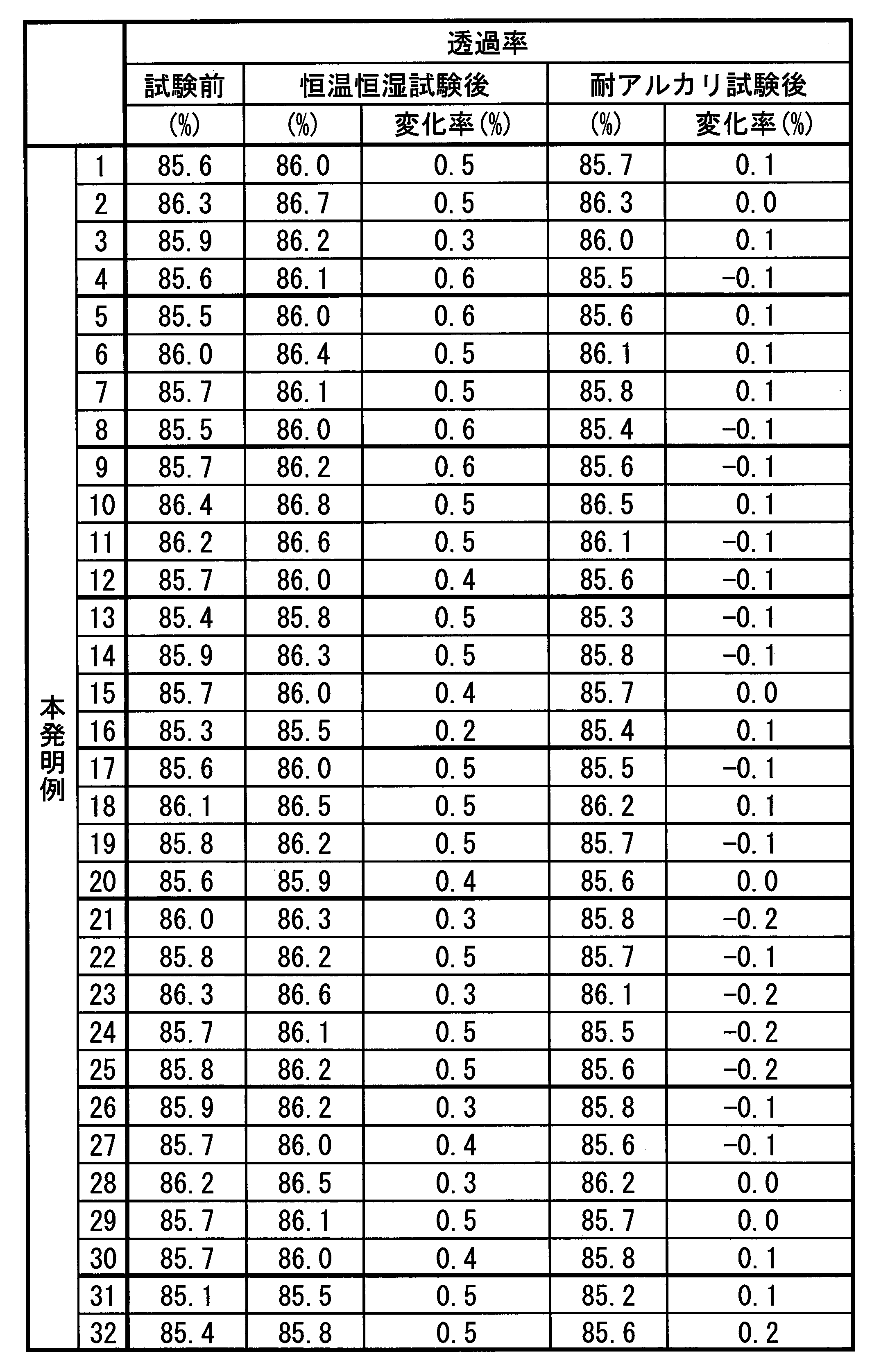
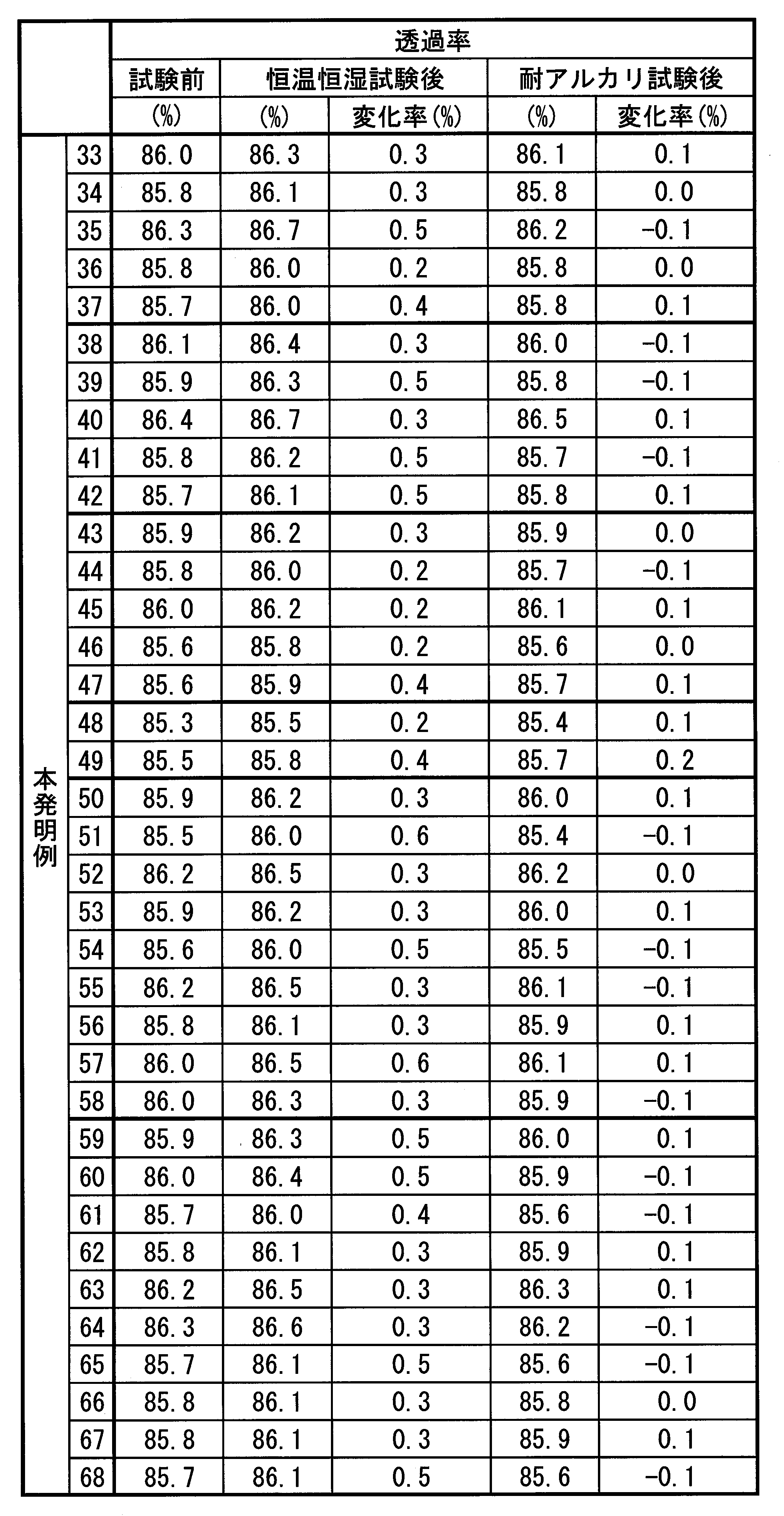
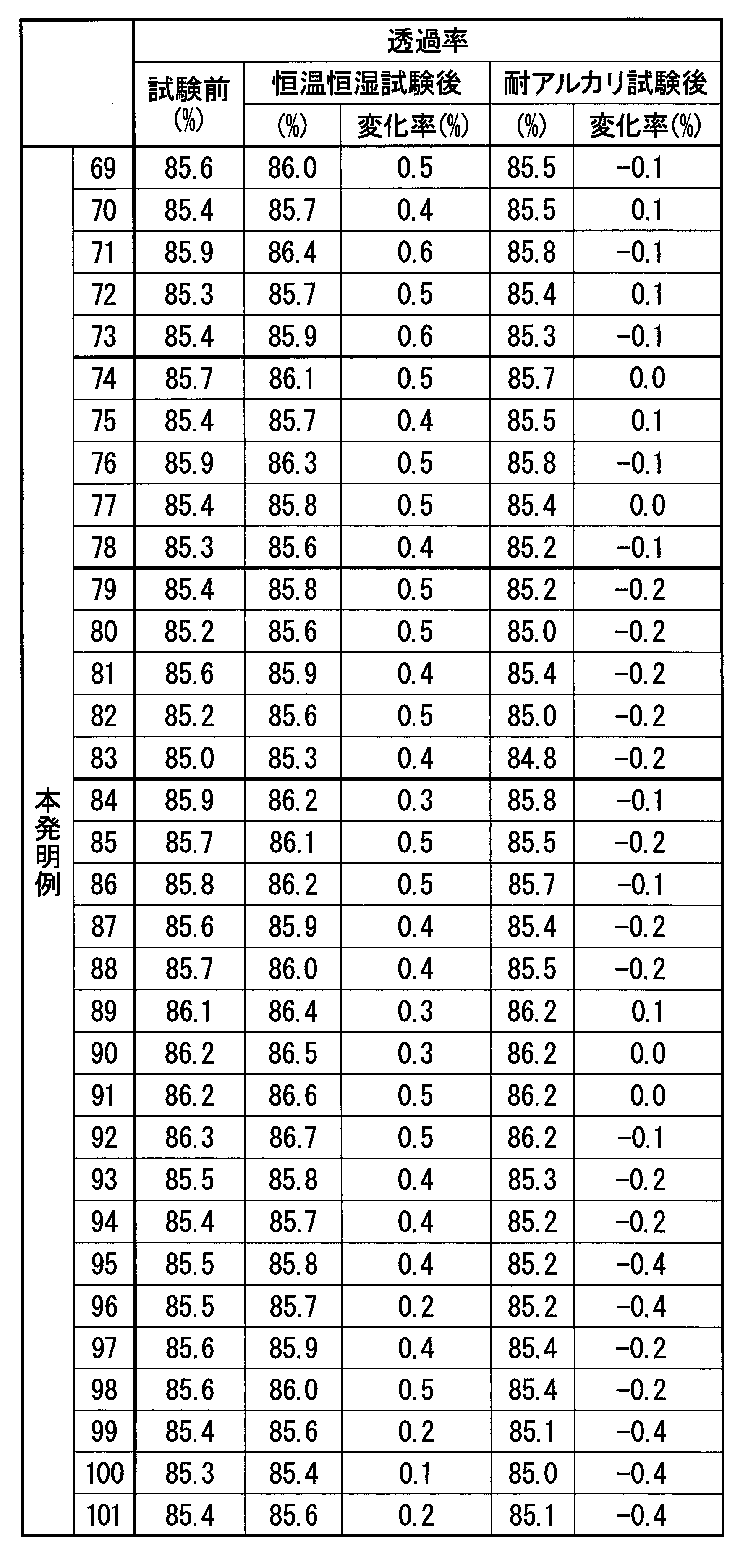
- ⁇ Transmissivity> Using a spectrophotometer (U4100 manufactured by Hitachi High-Technologies Corporation), a transmittance spectrum in a wavelength range of 400 nm to 800 nm was measured, and an average transmittance (transmittance) was obtained. The measurement results of transmittance are shown in Tables 9, 10, 11, and 12, respectively.
- ⁇ Constant temperature and humidity test> The sample was left in a constant temperature and humidity chamber of 85 ° C. and 85% humidity for 250 hours, and the transmittance and sheet resistance after the test were measured to evaluate the rate of change from before the test.
- ⁇ Alkali resistance test> The film was immersed in an alkaline resist removing solution (pH 9, TOK-104 manufactured by Tokyo Ohka Kogyo Co., Ltd.) at a temperature of 40 ° C. for 10 minutes, and the transmittance and sheet resistance after immersion were measured to evaluate the rate of change from before immersion.
- an alkaline resist removing solution pH 9, TOK-104 manufactured by Tokyo Ohka Kogyo Co., Ltd.
- ⁇ Patterning test by etching method About the above-mentioned laminated transparent conductive film, a resist film was formed on the laminated transparent conductive film in a wiring pattern shape of line width / space width: 30 ⁇ m / 30 ⁇ m by a photolithography method (photolithography method). This was subjected to batch etching using a mixed solution containing phosphoric acid and acetic acid (SEA-5 manufactured by Kanto Chemical Co., Inc.) as an etchant. The etching was performed without heating and with an appropriate etching time (20 seconds to 120 seconds). Further, the phosphoric acid content in the mixed solution was 55% by volume or less, and the acetic acid content was 30% by volume or less.
- SEA-5 manufactured by Kanto Chemical Co., Inc.
- FIGS. 7A and 7B a line is denoted by a symbol P, a space by a symbol S, an overetch by a symbol O, and the residue by a symbol R.
- a cross section of the pattern before removing the resist film (a cross section perpendicular to the line and space and perpendicular to the film formation surface of the substrate 20) is scanned at a magnification of 50000 using a scanning electron microscope (SU8000 manufactured by Hitachi High-Technologies Corporation). Observed at double. The observation result of the cross-sectional shape of Example 3 of the present invention is shown in FIG.
- the length L was measured with the point farthest from the end of the resist film 41 in the direction parallel to the film formation surface of the substrate 20 among the inner ends of the transparent conductive film 10 as the end of the laminated transparent conductive film 10.
- Tables 5, 6, 7, and 8 show the lengths of overetching of the samples of the present invention and the comparative example, respectively. Note that the length of overetching in Tables 5, 6, 7, and 8 is the value of the length L obtained by observing one cross section. Moreover, the resist was peeled off and the surface of the laminated film was visually observed.
- ⁇ Patterning test by lift-off method First, a resist solution is applied to the substrate, a photomask on which a wiring pattern of line width / space width: 30 ⁇ m / 30 ⁇ m is formed, exposed to ultraviolet rays with an exposure machine, and then the portion exposed to the developer is removed. Then, a reversal pattern was formed by photolithography. Next, a laminated transparent conductive film was formed on the substrate on which the reverse pattern was formed using the sputtering apparatus as described above.
- the formed wiring pattern was subjected to an optical microscope (KEYENCE).
- the accuracy of the electrode pattern was confirmed by observing at a magnification of 50 times with a laser microscope VK-X200 manufactured by the company.
- the average transmittance after film formation exceeds 85%, and the sheet resistance after film formation is 20 ⁇ / sq. It was confirmed that a laminated transparent conductive film having excellent transmittance and sufficiently low resistance was obtained.
- the average transmittance after film formation is 85% or less, and the sheet resistance after film formation is higher than that of the present invention example when compared with samples having the same film thickness of the Ag film. It was. It is presumed that Ag aggregation occurred in the Ag film.
- the sheet resistance is 10 ⁇ / sq.
- the sheet resistance is 10 ⁇ / sq.
- the average transmittance was greatly deteriorated to 76.4%.
- Comparative Example B by heating the glass substrate to 200 ° C., the film thickness is 180 nm and the sheet resistance is 10 ⁇ / sq. The average transmittance was 85% or less.
- the overetching length of the laminated film is 1 ⁇ m or less, and the transparent conductive oxide film It was confirmed that a wiring pattern having no residue can be formed with high accuracy.
- the length of the overetching O of the laminated film is larger than 1 ⁇ m, and the residue R of the transparent conductive oxide film is also generated. Depending on the etching, it is difficult to form a wiring pattern with high accuracy.
- the laminated transparent conductive film of the present invention has a sufficiently high transmittance, a sufficiently low electrical resistance, excellent environmental resistance and alkali resistance, and is unlikely to cause over-etching. It is suitable for.
Landscapes
- Chemical & Material Sciences (AREA)
- Engineering & Computer Science (AREA)
- Organic Chemistry (AREA)
- Materials Engineering (AREA)
- Mechanical Engineering (AREA)
- Chemical Kinetics & Catalysis (AREA)
- Metallurgy (AREA)
- Ceramic Engineering (AREA)
- Manufacturing & Machinery (AREA)
- Structural Engineering (AREA)
- Life Sciences & Earth Sciences (AREA)
- Environmental & Geological Engineering (AREA)
- General Life Sciences & Earth Sciences (AREA)
- Geology (AREA)
- Inorganic Chemistry (AREA)
- Non-Insulated Conductors (AREA)
- Laminated Bodies (AREA)
Abstract
Description
本願は、2016年3月23日に日本に出願された特願2016-058937号、及び2017年2月13日に日本に出願された特願2017-024386号に基づき優先権を主張し、その内容をここに援用する。
ここで、特許文献3、4に記載された積層透明導電膜において、さらなる電気抵抗の低下及び透過率の向上を図るためには、Ag膜の膜厚を薄くする必要がある。しかしながら、単にAg膜を薄くした場合には、Agが凝集しやすくなり、このAgの凝集によって表面プラズモン吸収が発生し、透過率が大幅に低下してしまうといった問題があった。また、Agの凝集によってAg膜が不連続膜となるため、電気抵抗も増加して導電性が低下してしまうといった問題があった。
さらに、リン酸、酢酸を含む酸性の混合液をエッチャントとして使用した場合には、Ag膜と透明導電酸化物膜とのエッチング速度の差が小さく、この積層透明導電膜を一括エッチングしても精度良く配線パターンを形成することができる。
また、この透明導電酸化物膜は耐アルカリ性が高いので、配線パターンを形成する際、アルカリ性のレジスト除去液を用いてレジスト膜を除去しても、積層透明導電膜の特性の劣化を抑制することができる。
この場合、透明導電酸化物膜中に含まれる全金属元素におけるGaの含有量が0.5原子%以上30原子%以下の範囲内とされているので、Ag膜の凝集を抑制し、電気抵抗の増加を抑制することができる。また、Tiの含有量が0.1原子%以上10.0原子%以下の範囲内とされているので、電気抵抗の増加を抑制しつつ、耐アルカリ性および耐環境性を向上させることができる。
この場合、透明導電酸化物膜中に含まれる全金属元素におけるGaの含有量が0.5原子%以上18.0原子%以下の範囲内とされているので、Ag膜の凝集をより抑制し、電気抵抗の増加をより一層抑制することができる。また、Tiの含有量が0.1原子%以上10.0原子%以下の範囲内とされているので、電気抵抗の増加を抑制しつつ、耐アルカリ性および耐環境性を向上させることができる。
この場合、透明導電酸化物膜中に含まれる全金属元素におけるGaの含有量が0.5原子%以上14.0原子%以下の範囲内とされているので、Ag膜の凝集をさら抑制し、電気抵抗の増加をさらに一層抑制することができる。また、Tiの含有量が0.1原子%以上10.0原子%以下の範囲内とされているので、電気抵抗の増加を抑制しつつ、耐アルカリ性および耐環境性を向上させることができる。
この場合、透明導電酸化物膜を形成している酸化物がYを含んでいるので、電気抵抗の増加を抑制しつつ、耐アルカリ性および耐環境性をさらに向上させることができる。
この場合、透明導電酸化物膜中に含まれる全金属元素におけるGaの含有量が0.5原子%以上30原子%以下の範囲内とされているので、Ag膜の凝集を抑制し、電気抵抗の増加を抑制することができる。また、Tiの含有量が0.1原子%以上10.0原子%以下の範囲内とされているので、電気抵抗の増加を抑制しつつ、耐アルカリ性および耐環境性を向上させることができる。さらに、Yの含有量が0.1原子%以上10.0原子%以下の範囲内とされているので、電気抵抗の増加を抑制しつつ耐アルカリ性を向上させることができる。
この場合、Cu,Sn,Sb,Ti,Mg,Zn,Ge,In,Al,Ga,Pd,Au,Pt,Bi,Mn,Sc,Y,Nd,Sm,Eu,Gd,Tb,Erのうちの1種又は2種以上を含有しているので、Ag膜の凝集がさらに抑制されることになり、Ag膜を10nm以下に極めて薄く形成しても、連続膜とすることができる。
この場合、Ag膜の厚さが10nm以下とされているので、透過率を向上させることができる。また、Ag膜の両面に上述の透明導電酸化物膜が形成されているので、Ag膜の厚さを10nm以下としても、Agの凝集がなく連続膜となるため、電気抵抗を低くすることができる。
この場合、可視光域の平均透過率が85%以上、かつ、シート抵抗値が20Ω/sq.以下とされているので、積層透明導電膜は十分に高い透過率及び十分に低い電気抵抗を有しており、微細化された透明電極膜又は透明配線膜として使用することができる。
本発明の積層配線膜は、上述の積層透明導電膜からなることから、低い電気抵抗と高い透過率を有する。
本実施形態における積層透明導電膜10は、各種ディスプレイ及びタッチパネルの透明電極膜として使用されるものであり、特に、タブレットサイズ以上の静電容量タイプのタッチパネルにおいて使用されるものとされている。
なお、積層透明導電膜10の波長400~800nmの可視光域の平均透過率は85%以上であることが好ましく、86%以上であることがさらに好ましい。平均透過率は高いほど好ましいので上限値は特に限定されないが、95%が好ましく、90%がより好ましい。また、積層透明導電膜10のシート抵抗値は20Ω/sq.以下であることが好ましく、5Ω/sq.以下であることがさらに好ましい。積層透明導電膜10のシート抵抗値は低いほど好ましいので下限値は特に限定されないが、0.5Ω/sq.が好ましく、1Ω/sq.がより好ましい。
なお、添加元素の含有量は、Ag膜12の吸収率の増加(透過率の低下)及び電気抵抗の増加を抑制する観点から、10.0原子%以下に制限することが望ましく、2.0原子%以下であることがさらに好ましい。
なお、本実施形態では、Ag膜12は、Cu,Sn,Sb,Ti,Mg,Zn,Ge,In,Al,Ga,Pd,Au,Pt,Bi,Mn,Sc,Y,Nd,Sm,Eu,Gd,Tb,Erのうちの1種又は2種以上を合計で0.2原子%以上10.0原子%以下含有し、残部がAg及び不可避不純物からなるAg合金で構成されている。
ここで、Cu,Sn,Sb,Ti,Mg,Zn,Ge,In,Al,Ga,Pd,Au,Pt,Bi,Mn,Sc,Y,Nd,Sm,Eu,Gd,Tb,Erのうちの1種又は2種以上の合計含有量が0.2原子%未満の場合には、上述の作用効果を十分に奏功せしめることができないおそれがある。一方、Cu,Sn,Sb,Ti,Mg,Zn,Ge,In,Al,Ga,Pd,Au,Pt,Bi,Mn,Sc,Y,Nd,Sm,Eu,Gd,Tb,Erのうちの1種又は2種以上の合計含有量が10.0原子%を超えるとAg膜12の透過率が低下し、かつ、抵抗値が上昇するおそれがある。
このような理由から、本実施形態では、Ag膜12を構成するAg合金におけるCu,Sn,Sb,Ti,Mg,Zn,Ge,In,Al,Ga,Pd,Au,Pt,Bi,Mn,Sc,Y,Nd,Sm,Eu,Gd,Tb,Erのうちの1種又は2種以上の合計含有量を0.2原子%以上10.0原子%以下の範囲内に規定している。
すなわち、第1透明導電酸化物膜11及び第2透明導電酸化物膜13は、Zn酸化物に、Ga,Ti、またはGa,Ti及びYが添加されたものとされている。
本実施形態では、第1透明導電酸化物膜11及び第2透明導電酸化物膜13は、それぞれの透明導電酸化物膜中に含まれる全金属元素におけるGa,Ti及びYの原子割合が、Ga;0.5原子%以上30.0原子%以下、Ti;0.1原子%以上10.0原子%以下、Y;0.1原子%以上10.0原子%以下とされている。
なお、第1透明導電酸化物膜11及び第2透明導電酸化物膜13は同一の組成である必要はなく、上述の組成の範囲内とされていればよい。
なお、Ag膜12におけるAgの凝集を抑制するためには、Gaの含有量の下限を1.0原子%以上とすることが好ましく、2.0原子%以上とすることがさらに好ましい。また、第1透明導電酸化物膜11及び第2透明導電酸化物膜13における電気抵抗の増加を確実に抑制するためには、Gaの含有量の上限を25.0原子%以下とすることが好ましく、20.0原子%以下とすることがより好ましく、18.0原子%以下とすることがさらに好ましく、14.0原子%以下とすることがなお一層好ましい。
なお、第1透明導電酸化物膜11及び第2透明導電酸化物膜13の耐アルカリ性および耐環境性を確実に向上させるためには、Tiの含有量の下限を0.2原子%以上とすることが好ましく、0.5原子%以上とすることがさらに好ましい。また、第1透明導電酸化物膜11及び第2透明導電酸化物膜13における電気抵抗の増加を確実に抑制するためには、Tiの含有量の上限を9.0原子%以下とすることが好ましく、8.0原子%以下とすることがさらに好ましい。
なお、第1透明導電酸化物膜11及び第2透明導電酸化物膜13の耐アルカリ性を確実に向上させるためには、Yの含有量の下限を0.2原子%以上とすることが好ましく、0.5原子%以上とすることがさらに好ましい。また、第1透明導電酸化物膜11及び第2透明導電酸化物膜13における電気抵抗の増加を確実に抑制するためには、Yの含有量の上限を9.0原子%以下とすることが好ましく、8.0原子%以下とすることがさらに好ましい。
t1=550/(4×n1)×k1,t3=550/(4×n3)×k3
ここで、n1,n3は、それぞれ第1透明導電酸化物膜11の屈折率(n1)及び第2透明導電酸化物膜13の屈折率(n3)である。また、k1,k3は、それぞれ第1透明導電酸化物膜11の係数(k1)及び第2透明導電酸化物膜13の係数(k3)である。すなわち、上記光学シミュレーションでは、可視光域の透過率が向上するように係数k1、k3の値を最適化して膜厚を求める。
本実施形態では、上述の光学シミュレーションの結果、第1透明導電酸化物膜11の膜厚t1及び第2透明導電酸化物膜13の膜厚t3を40nmに設定している。これらの膜厚は、係数k1,k3を0.6とした場合の膜厚である。
本実施形態である積層配線膜30は、図2に示すように、図1に示す積層透明導電膜10に配線パターンが形成されたものである。ここで、本実施形態である積層配線膜30においては、配線パターンは、ライン幅及びライン間のスペースの幅が1μm以上900μm以下の範囲内である。
まず、基材としての基板20の成膜面に、本実施形態である積層透明導電膜10を成膜する(積層透明導電膜成膜工程S11)。
この積層透明導電膜成膜工程S11においては、基板20の上に下地層として第1透明導電酸化物膜11を成膜する。第1透明導電酸化物膜11は、膜組成を制御しやすい焼結ターゲットを用いて、DCスパッタによって成膜することが好ましい。次に、成膜された第1透明導電酸化物膜11の上に、Agターゲットを用いてDCスパッタによってAg膜12を成膜する。このAgターゲットは、成膜されるAg膜12の組成に応じた組成とされている。そして、成膜されたAg膜12の上に、透明導電酸化物ターゲットを用いてDCスパッタによって第2透明導電酸化物膜13を成膜する。なお、透明導電酸化物ターゲットは、膜組成を制御しやすい焼結ターゲットとすることが好ましい。このようにして、本実施形態である積層透明導電膜10を成膜する。
次に、レジスト膜41が形成された積層透明導電膜10に対して、リン酸、酢酸を含む酸性の混合液をエッチャントに用いて、エッチングを一括して行う(エッチング工程S13)。ここで、リン酸、酢酸を含む酸性の混合液においては、リン酸の含有量が55体積%以下、酢酸の含有量が30体積%以下であることが好ましい。混合液は、リン酸及び酢酸以外に硝酸を20体積%以下含んでいても良い。
これにより、配線パターン形状のレジスト膜41の下側に位置する積層透明導電膜10が残り、配線パターンを有する積層配線膜30が形成される。
さらに、第1透明導電酸化物膜11及び第2透明導電酸化物膜13が、耐環境性に優れていることから、湿度の高い環境下で使用した場合であっても、Ag膜12への水分の侵入を抑制でき、Agの凝集を抑制することができる。
よって、Ag膜12においてAgの凝集による表面プラズモン吸収の発生を防止でき、高い透過率を得ることができる。また、Ag膜12が連続膜となるため、電気抵抗も低くすることができる。
また、本実施形態では、TiまたはTi及びYの添加によって第1透明導電酸化物膜11及び第2透明導電酸化物膜13の耐アルカリ性が向上しているので、レジスト膜除去工程S14において、アルカリ性のレジスト除去液を用いてレジスト膜を除去しても、積層配線膜30の特性の劣化を抑制することができる。
例えば、本実施形態では、Ag膜12をCu,Sn,Sb,Ti,Mg,Zn,Ge,In,Al,Ga,Pd,Au,Pt,Bi,Mn,Sc,Y,Nd,Sm,Eu,Gd,Tb,Erのうちの1種又は2種以上を合計で0.2原子%以上10.0原子%以下含有し、残部がAg及び不可避不純物からなるAg合金で構成したものとして説明したが、Ag膜12はこれに限定されることはなく、純Agや、Agに固溶する他の金属元素を含有するAg合金であってもよい。
図5及び図6に示す積層配線膜30の製造方法においては、まず、基板20の成膜面にレジスト膜41を成膜し、このレジスト膜41に露光・現像することで、配線パターンを反転させた反転パターンを形成する(レジスト膜形成工程S21)。
次に、アルカリ性のレジスト除去液を用いて、レジスト膜41を除去する(レジスト膜除去工程S23)。
これにより、反転パターン状のレジスト膜41上に成膜された積層透明導電膜10は除去され、配線パターンを有する積層配線膜30が形成される。
なお、本発明の実施例および比較例におけるAg膜及び透明導電酸化物膜の膜厚は、膜厚計(アルバック社製 DEKTAK)を用いて測定した。
また、透明導電酸化物膜およびAg合金膜の組成は、ICP発光分光装置(日立ハイテクサイエンス社製ICP発光分光分析装置STS-3500DD)を用いて元素の定量分析を行うことにより求めた。
Ag膜の作製には、表1、2、3、4に記載された組成のAgターゲットを用いた。それぞれの膜の成膜条件を以下に示す。
なお、比較例において、ITO膜(In2O3にSnを添加した酸化物)の組成は、In:35.6原子%、Sn:3.6原子%、O:60.8原子%であった。
GZO膜(ZnOにGaを添加した酸化物)の組成は、Zn:47.3原子%、Ga:2.2原子%、O:50.5原子%であった。
スパッタリング装置:DCマグネトロンスパッタ装置(アルバック社製CS-200)
磁界強度:1000Gauss(ターゲット直上、垂直成分)
到達真空度:5×10⁻⁵Pa以下
スパッタリングガス:Ar+O2の混合ガス(O2の混合比:1%)
スパッタリングガス圧:0.4Pa
スパッタリングパワー:DC100W
スパッタリング装置:DCマグネトロンスパッタ装置(アルバック社製CS-200)
磁界強度:1000Gauss(ターゲット直上、垂直成分)
到達真空度:5×10⁻⁵Pa以下
スパッタリングガス:Ar
スパッタリングガス圧:0.5Pa
スパッタリングパワー:DC100W
また、恒温恒湿試験後のシート抵抗及び透過率、及び、耐アルカリ性試験後のシート抵抗及び透過率を評価した。
さらに、得られた積層透明導電膜について、エッチング法によるパターニング試験、及び、リフトオフ法によるパターニング試験を行った。
評価方法について以下に示す。
表面抵抗測定器(三菱油化社製 Loresta AP MCP-T400)を用いて、四探針法によってシート抵抗を測定した。シート抵抗の測定結果を表5、6、7、8にそれぞれ示す。
<透過率>
分光光度計(日立ハイテクノロジーズ社製 U4100)を用いて、400nmから800nmの波長範囲における透過率スペクトルを測定し、平均透過率(透過率)を求めた。透過率の測定結果を表9、10、11、12にそれぞれ示す。
温度85℃、湿度85%の恒温恒湿槽に250時間放置し、試験後の透過率及びシート抵抗を測定して試験前からの変化率を評価した。
温度40℃のアルカリ性のレジスト除去液(pH9、東京応化工業社製TOK-104)に10分浸漬し、浸漬後の透過率及びシート抵抗を測定して、浸漬前からの変化率を評価した。
上述の積層透明導電膜について、フォトリソ法(フォトリソグラフィー法)により積層透明導電膜の上にレジスト膜を、ライン幅/スペース幅:30μm/30μmの配線パターン状に形成した。これを、リン酸、酢酸を含む混合液(関東化学社製SEA-5)をエッチャントとして用いて、一括エッチングを行った。なお、エッチングは無加熱でそれぞれ適切なエッチング時間(20秒から120秒)で行った。また、混合液におけるリン酸の含有量を55体積%以下、酢酸の含有量を30体積%以下とした。
その後、アルカリ性のレジスト除去液(pH9、東京応化工業社製TOK-104)を用いてレジスト膜を除去した後、形成された配線パターンを光学顕微鏡(KEYENCE社製レーザーマイクロスコープVK-X200)により倍率50倍で観察し、透明導電酸化物膜の残渣の有無を確認した。詳細には、エッチングされずに針状や粒状などの形で残った透明導電酸化物膜の存在が認められる場合に透明導電酸化物膜の残渣があると判断し、それ以外を透明導電酸化物膜の残渣がないと判断した。本発明例3及び比較例2の観察結果を図7(a)、(b)にそれぞれ示す。なお、図7(a)、(b)においては、ラインに符号P、スペースに符号S、オーバーエッチングに符号O、残渣に符号Rを付している。
また、レジスト膜を除去する前のパターンの断面(ライン及びスペースに直交する、基板20の成膜面に垂直な断面)を、走査電子顕微鏡(日立ハイテクノロジーズ社製のSU8000)を用いて倍率50000倍で観察した。本発明例3の断面形状の観察結果を図8に示す。レジスト膜41の内部までエッチングされた部分をオーバーエッチングの長さとして、レジスト膜41の端部から内部の積層透明導電膜10の端部までの長さL(基板20の成膜面に平行な方向の長さ)をそれらの観察像から測定して求めた。なお、基板20との間に積層透明導電膜10が本来残っているべきレジストパターンの境界部(縁部)をレジスト膜41の端部とし、レジストパターンと基板20との間に残っている積層透明導電膜10の内側の端部のうち基板20の成膜面に平行な方向においてレジスト膜41の端部から最も離れた点を積層透明導電膜10の端部として長さLを測定した。本発明例および比較例の各サンプルのオーバーエッチングの長さを表5、6、7、8にそれぞれ示す。なお、表5、6、7、8のオーバーエッチングの長さは1つの断面を観察して得られた長さLの値である。
また、レジストを剥離して積層膜の表面を目視で観察した。
まず、基板にレジスト液を塗布して、ライン幅/スペース幅:30μm/30μmの配線パターンが形成されたフォトマスクを付けて露光機で紫外線を当てた後、現像液で感光された部分を除去し、フォトリソ法によって反転パターンを形成した。
次に、反転パターンが形成された基板の上に、上述のようにスパッタリング装置を用いて積層透明導電膜を成膜した。
次に、レジスト除去液(pH9、東京応化工業社製TOK-104)に浸漬し、レジスト膜の上に成膜された積層透明導電膜を除去した後、形成された配線パターンを光学顕微鏡(KEYENCE社製レーザーマイクロスコープVK-X200)により倍率50倍で観察し、電極パターンの精度を確認した。なお、ライン(P)に膜の剥離やレジストの残渣が認められた場合に電極パターンが精度良く形成されなかったと判断し、それ以外を電極パターンが精度良く形成されたと判断した。


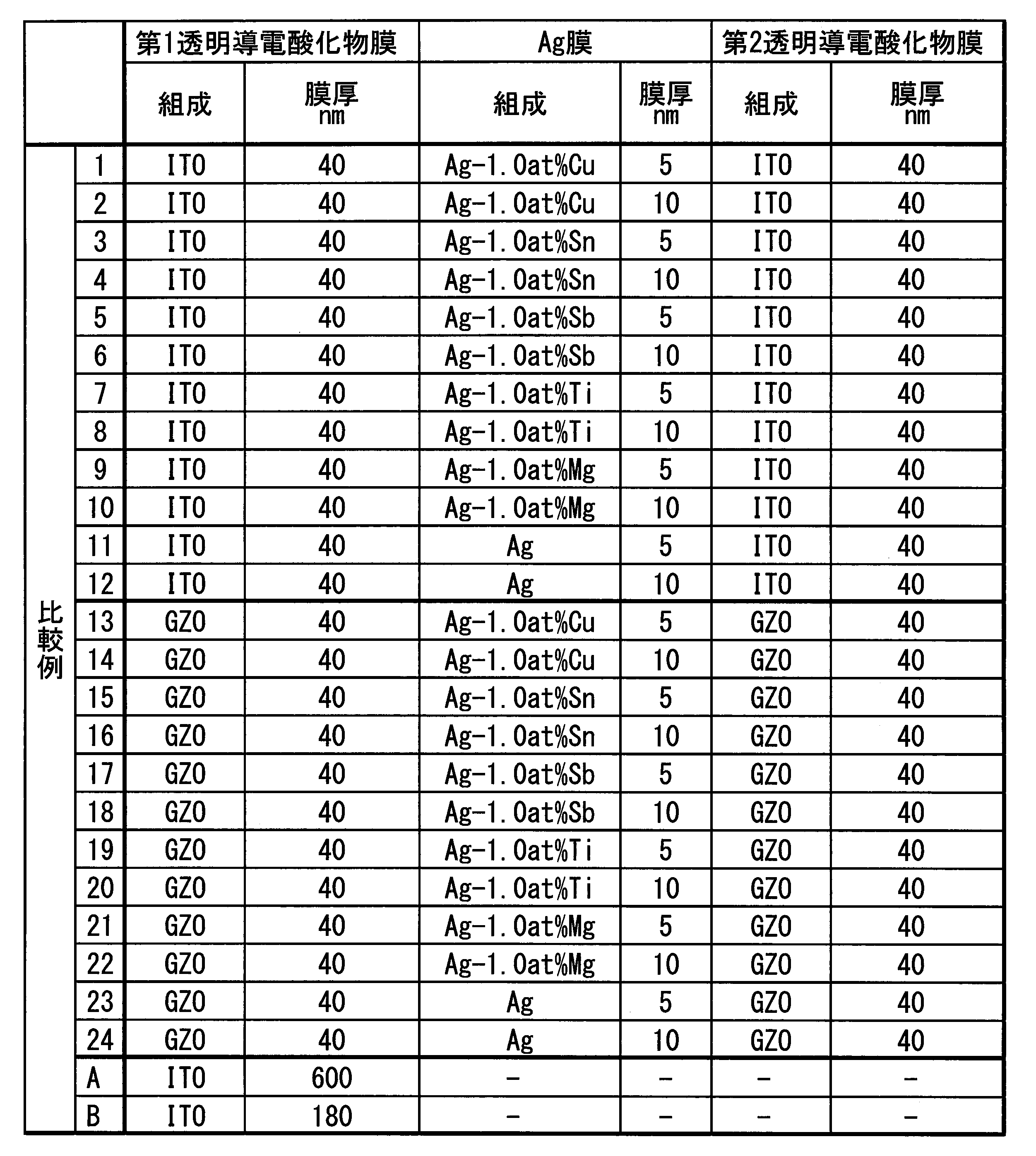


一方、比較例においては、成膜後の平均透過率がいずれも85%以下であり、成膜後のシート抵抗はAg膜の膜厚が同じサンプルで比較すると本発明例に比べて高くなっていた。Ag膜においてAgの凝集が発生したためと推測される。
また、比較例Aでは、ITO単層膜を600nmと厚く形成することで、シート抵抗が10Ω/sq.以下となったが、平均透過率が76.4%と大きく劣化した。
さらに、比較例Bでは、ガラス基板を200℃に加熱することで、膜厚が180nmでシート抵抗が10Ω/sq.以下となったが、平均透過率は85%以下であった。
一方、比較例では、A、Bを除き、恒温恒湿試験後の透過率又はシート抵抗の変化率が大きく、耐環境性が不十分であった。
一方、比較例では、比較例13~24のサンプルで、耐アルカリ性試験後の透過率およびシート抵抗の変化率が大きく、耐アルカリ性が不十分であった。
一方、比較例では、表8及び図7(b)に示すように、いずれも積層膜のオーバーエッチングOの長さは1μmより大きく、また、透明導電酸化物膜の残渣Rも発生し、一括エッチングによっては、配線パターンを精度良く形成することが困難であった。
また、レジストを剥離して積層膜の表面を目視で観察したところ、本発明例では試験前と比べて変化は見られなかったのに対し、Y、Tiの添加がないGZO膜を透明導電酸化物とした比較例13~24の積層膜では、レジスト剥離後に、膜剥がれがところどころ観察された。
一方、Y、Tiの添加がないGZO膜を透明導電酸化物とした比較例13~24の積層膜では、レジスト除去後に、膜の剥離がところどころ観察された。
11 第1透明導電酸化物膜(透明導電酸化物膜)
12 Ag膜
13 第2透明導電酸化物膜(透明導電酸化物膜)
20 基板
30 積層配線膜
41 レジスト膜
Claims (12)
- AgまたはAg合金よりなるAg膜と、前記Ag膜の両面に配置された透明導電酸化物膜と、を有し、
前記透明導電酸化物膜は、Zn,GaおよびTiを含む酸化物から形成されていることを特徴とする積層透明導電膜。 - 前記透明導電酸化物膜中に含まれる全金属元素の原子割合が、Ga;0.5原子%以上30.0原子%以下、Ti;0.1原子%以上10.0原子%以下、残Znとされていることを特徴とする請求項1に記載の積層透明導電膜。
- 前記透明導電酸化物膜中に含まれる全金属元素の原子割合が、Ga;0.5原子%以上18.0原子%以下、Ti;0.1原子%以上10.0原子%以下、残Znとされていることを特徴とする請求項2に記載の積層透明導電膜。
- 前記透明導電酸化物膜中に含まれる全金属元素の原子割合が、Ga;0.5原子%以上14.0原子%以下、Ti;0.1原子%以上10.0原子%以下、残Znとされていることを特徴とする請求項3に記載の積層透明導電膜。
- 前記透明導電酸化物膜を形成している酸化物が、さらにYを含むことを特徴とする請求項1に記載の積層透明導電膜。
- 前記透明導電酸化物膜中に含まれる全金属元素の原子割合が、Ga;0.5原子%以上30.0原子%以下、Ti;0.1原子%以上10.0原子%以下、Y;0.1原子%以上10.0原子%以下、残Znとされていることを特徴とする請求項5に記載の積層透明導電膜。
- 前記Ag膜は、Cu,Sn,Sb,Ti,Mg,Zn,Ge,In,Al,Ga,Pd,Au,Pt,Bi,Mn,Sc,Y,Nd,Sm,Eu,Gd,Tb,Erのうちの1種又は2種以上を合計で0.2原子%以上10.0原子%以下含有し、残部がAg及び不可避不純物からなるAg合金で構成されていることを特徴とする請求項1から請求項6のいずれか一項に記載の積層透明導電膜。
- 前記Ag膜の厚さが10nm以下とされていることを特徴とする請求項1から請求項7のいずれか一項に記載の積層透明導電膜。
- 波長400~800nmの可視光域の平均透過率が85%以上、シート抵抗値が20Ω/sq.以下であることを特徴とする請求項1から請求項8のいずれか一項に記載の積層透明導電膜。
- 請求項1から請求項9のいずれか一項に記載の積層透明導電膜からなり、配線パターンを有することを特徴とする積層配線膜。
- 請求項10に記載された積層配線膜の製造方法であって、
基材の成膜面に、前記Ag膜及び前記透明導電酸化物膜を含む前記積層透明導電膜を成膜する積層透明導電膜成膜工程と、
前記積層透明導電膜の上に配線パターン状のレジスト膜を形成するレジスト膜形成工程と、
前記レジスト膜が形成された前記積層透明導電膜に対して、リン酸、酢酸を含む酸性の混合液をエッチャントに用いて、エッチングを一括して行うエッチング工程と、
エッチング後に前記レジスト膜を除去するレジスト膜除去工程と、
を備えていることを特徴とする積層配線膜の製造方法。 - 請求項10に記載された積層配線膜の製造方法であって、
基材の成膜面に配線パターンの反転パターン状のレジスト膜を形成するレジスト膜形成工程と、
前記レジスト膜が形成された前記基材の成膜面に、前記Ag膜及び前記透明導電酸化物膜を含む前記積層透明導電膜を成膜する積層透明導電膜成膜工程と、
前記レジスト膜を除去するレジスト膜除去工程と、
を備えていることを特徴とする積層配線膜の製造方法。
Priority Applications (4)
| Application Number | Priority Date | Filing Date | Title |
|---|---|---|---|
| US16/086,165 US20190105872A1 (en) | 2016-03-23 | 2017-03-22 | Multilayer transparent conductive film, multilayer wiring film, and method of forming multilayer wiring film |
| EP17770249.5A EP3435385B1 (en) | 2016-03-23 | 2017-03-22 | Laminated transparent conductive film, laminated wiring film, and method for producing laminated wiring film |
| CN201780019852.7A CN108885922B (zh) | 2016-03-23 | 2017-03-22 | 层叠透明导电膜、层叠布线膜及层叠布线膜的制造方法 |
| KR1020187025939A KR102333536B1 (ko) | 2016-03-23 | 2017-03-22 | 적층 투명 도전막, 적층 배선막 및 적층 배선막의 제조 방법 |
Applications Claiming Priority (4)
| Application Number | Priority Date | Filing Date | Title |
|---|---|---|---|
| JP2016-058937 | 2016-03-23 | ||
| JP2016058937 | 2016-03-23 | ||
| JP2017024386A JP6888318B2 (ja) | 2016-03-23 | 2017-02-13 | 積層透明導電膜、積層配線膜及び積層配線膜の製造方法 |
| JP2017-024386 | 2017-02-13 |
Publications (1)
| Publication Number | Publication Date |
|---|---|
| WO2017164209A1 true WO2017164209A1 (ja) | 2017-09-28 |
Family
ID=59899448
Family Applications (1)
| Application Number | Title | Priority Date | Filing Date |
|---|---|---|---|
| PCT/JP2017/011343 Ceased WO2017164209A1 (ja) | 2016-03-23 | 2017-03-22 | 積層透明導電膜、積層配線膜及び積層配線膜の製造方法 |
Country Status (1)
| Country | Link |
|---|---|
| WO (1) | WO2017164209A1 (ja) |
Citations (9)
| Publication number | Priority date | Publication date | Assignee | Title |
|---|---|---|---|---|
| JP2004156070A (ja) * | 2002-11-01 | 2004-06-03 | Kanto Chem Co Inc | 透明導電膜を含む積層膜のエッチング液組成物 |
| JP2007250430A (ja) * | 2006-03-17 | 2007-09-27 | Sumitomo Metal Mining Co Ltd | 透明導電膜、およびこれを用いた透明導電性フィルム |
| JP2009298649A (ja) * | 2008-06-13 | 2009-12-24 | Sumitomo Metal Mining Co Ltd | 酸化物焼結体、ターゲット、およびそれを用いて得られる透明導電膜、導電性積層体 |
| WO2011122497A1 (ja) * | 2010-03-31 | 2011-10-06 | リンテック株式会社 | 透明導電性フィルムおよびその製造方法並びに透明導電性フィルムを用いた電子デバイス |
| WO2011126074A1 (ja) * | 2010-04-08 | 2011-10-13 | 東ソー株式会社 | 酸化亜鉛系透明導電膜、その製造方法及び用途 |
| JP2012054006A (ja) * | 2010-08-31 | 2012-03-15 | Gunze Ltd | 透明導電性ガスバリヤフィルム及びその製造方法 |
| WO2014097963A1 (ja) * | 2012-12-17 | 2014-06-26 | 住友化学株式会社 | 酸化亜鉛系透明導電膜 |
| WO2016024615A1 (ja) * | 2014-08-12 | 2016-02-18 | 三菱マテリアル株式会社 | 積層膜、積層配線膜及び積層配線膜の製造方法 |
| WO2016111202A1 (ja) * | 2015-01-09 | 2016-07-14 | 三菱マテリアル株式会社 | 積層膜 |
-
2017
- 2017-03-22 WO PCT/JP2017/011343 patent/WO2017164209A1/ja not_active Ceased
Patent Citations (9)
| Publication number | Priority date | Publication date | Assignee | Title |
|---|---|---|---|---|
| JP2004156070A (ja) * | 2002-11-01 | 2004-06-03 | Kanto Chem Co Inc | 透明導電膜を含む積層膜のエッチング液組成物 |
| JP2007250430A (ja) * | 2006-03-17 | 2007-09-27 | Sumitomo Metal Mining Co Ltd | 透明導電膜、およびこれを用いた透明導電性フィルム |
| JP2009298649A (ja) * | 2008-06-13 | 2009-12-24 | Sumitomo Metal Mining Co Ltd | 酸化物焼結体、ターゲット、およびそれを用いて得られる透明導電膜、導電性積層体 |
| WO2011122497A1 (ja) * | 2010-03-31 | 2011-10-06 | リンテック株式会社 | 透明導電性フィルムおよびその製造方法並びに透明導電性フィルムを用いた電子デバイス |
| WO2011126074A1 (ja) * | 2010-04-08 | 2011-10-13 | 東ソー株式会社 | 酸化亜鉛系透明導電膜、その製造方法及び用途 |
| JP2012054006A (ja) * | 2010-08-31 | 2012-03-15 | Gunze Ltd | 透明導電性ガスバリヤフィルム及びその製造方法 |
| WO2014097963A1 (ja) * | 2012-12-17 | 2014-06-26 | 住友化学株式会社 | 酸化亜鉛系透明導電膜 |
| WO2016024615A1 (ja) * | 2014-08-12 | 2016-02-18 | 三菱マテリアル株式会社 | 積層膜、積層配線膜及び積層配線膜の製造方法 |
| WO2016111202A1 (ja) * | 2015-01-09 | 2016-07-14 | 三菱マテリアル株式会社 | 積層膜 |
Similar Documents
| Publication | Publication Date | Title |
|---|---|---|
| KR102333536B1 (ko) | 적층 투명 도전막, 적층 배선막 및 적층 배선막의 제조 방법 | |
| CN108886857B (zh) | 层叠反射电极膜、层叠反射电极图案及层叠反射电极图案的制造方法 | |
| WO2016024615A1 (ja) | 積層膜、積層配線膜及び積層配線膜の製造方法 | |
| US20010030170A1 (en) | Transparent conductive film and process for forming a transparent electrode | |
| JP6870332B2 (ja) | 積層透明導電膜、積層配線膜及び積層配線膜の製造方法 | |
| CN106796885B (zh) | 透明导电配线及透明导电配线的制造方法 | |
| KR101350648B1 (ko) | 전자부품용 적층 배선막 및 피복층 형성용 스퍼터링 타겟재 | |
| JP4971618B2 (ja) | 表示用電極パターン製造方法 | |
| WO2017131183A1 (ja) | 積層透明導電膜、積層配線膜及び積層配線膜の製造方法 | |
| JP4655281B2 (ja) | 薄膜配線層 | |
| WO2017164211A1 (ja) | 積層反射電極膜、積層反射電極パターン、積層反射電極パターンの製造方法 | |
| WO2017164209A1 (ja) | 積層透明導電膜、積層配線膜及び積層配線膜の製造方法 | |
| WO2016111202A1 (ja) | 積層膜 | |
| KR101182013B1 (ko) | 박막 트랜지스터 기판 및 박막 트랜지스터 기판을 구비한 표시 디바이스 | |
| JP6565666B2 (ja) | 積層透明導電膜、積層配線膜及び積層配線膜の製造方法 | |
| JP6597284B2 (ja) | 積層透明導電膜、積層配線膜及び積層配線膜の製造方法 | |
| WO2016136953A1 (ja) | 透明導電配線、及び、透明導電配線の製造方法 | |
| JP2016130010A (ja) | 積層膜 | |
| JP6123285B2 (ja) | 積層膜 | |
| WO2013047245A1 (ja) | 電極付き基板 | |
| JP2018170360A (ja) | 導電膜,電極,電子機器,静電容量型入力装置及び電極の製造方法 |
Legal Events
| Date | Code | Title | Description |
|---|---|---|---|
| ENP | Entry into the national phase |
Ref document number: 20187025939 Country of ref document: KR Kind code of ref document: A |
|
| NENP | Non-entry into the national phase |
Ref country code: DE |
|
| WWE | Wipo information: entry into national phase |
Ref document number: 2017770249 Country of ref document: EP |
|
| ENP | Entry into the national phase |
Ref document number: 2017770249 Country of ref document: EP Effective date: 20181023 |
|
| 121 | Ep: the epo has been informed by wipo that ep was designated in this application |
Ref document number: 17770249 Country of ref document: EP Kind code of ref document: A1 |