WO2017164277A1 - 組織採取デバイス - Google Patents
組織採取デバイス Download PDFInfo
- Publication number
- WO2017164277A1 WO2017164277A1 PCT/JP2017/011624 JP2017011624W WO2017164277A1 WO 2017164277 A1 WO2017164277 A1 WO 2017164277A1 JP 2017011624 W JP2017011624 W JP 2017011624W WO 2017164277 A1 WO2017164277 A1 WO 2017164277A1
- Authority
- WO
- WIPO (PCT)
- Prior art keywords
- puncture tube
- tissue
- sheath member
- cylindrical body
- puncture
- Prior art date
- Legal status (The legal status is an assumption and is not a legal conclusion. Google has not performed a legal analysis and makes no representation as to the accuracy of the status listed.)
- Ceased
Links
Images




Classifications
-
- A—HUMAN NECESSITIES
- A61—MEDICAL OR VETERINARY SCIENCE; HYGIENE
- A61B—DIAGNOSIS; SURGERY; IDENTIFICATION
- A61B10/00—Instruments for taking body samples for diagnostic purposes; Other methods or instruments for diagnosis, e.g. for vaccination diagnosis, sex determination or ovulation-period determination; Throat striking implements
- A61B10/02—Instruments for taking cell samples or for biopsy
- A61B10/0233—Pointed or sharp biopsy instruments
- A61B10/0266—Pointed or sharp biopsy instruments means for severing sample
-
- A—HUMAN NECESSITIES
- A61—MEDICAL OR VETERINARY SCIENCE; HYGIENE
- A61B—DIAGNOSIS; SURGERY; IDENTIFICATION
- A61B10/00—Instruments for taking body samples for diagnostic purposes; Other methods or instruments for diagnosis, e.g. for vaccination diagnosis, sex determination or ovulation-period determination; Throat striking implements
- A61B10/0096—Casings for storing test samples
-
- A—HUMAN NECESSITIES
- A61—MEDICAL OR VETERINARY SCIENCE; HYGIENE
- A61B—DIAGNOSIS; SURGERY; IDENTIFICATION
- A61B10/00—Instruments for taking body samples for diagnostic purposes; Other methods or instruments for diagnosis, e.g. for vaccination diagnosis, sex determination or ovulation-period determination; Throat striking implements
- A61B10/02—Instruments for taking cell samples or for biopsy
-
- A—HUMAN NECESSITIES
- A61—MEDICAL OR VETERINARY SCIENCE; HYGIENE
- A61B—DIAGNOSIS; SURGERY; IDENTIFICATION
- A61B17/00—Surgical instruments, devices or methods
- A61B17/34—Trocars; Puncturing needles
- A61B17/3417—Details of tips or shafts, e.g. grooves, expandable, bendable; Multiple coaxial sliding cannulas, e.g. for dilating
- A61B17/3421—Cannulas
Definitions
- the present invention relates to a device capable of quantitatively collecting tissue.
- Regenerative medicine products are made by processing human cells from human tissues and other materials. In order to produce a product such as regenerative medicine, it is necessary to secure the amount of tissue necessary for production. Therefore, the human body is cut open with a scalpel or the like, and the tissue is collected, but this method is invasive. High and has a great impact on the human body.
- tissue collection needle for biopsy, etc., but this is just for collecting a small amount of tissue for examination, and it is necessary for a regenerative medicine product. In order to secure the tissue, it is necessary to use such a needle multiple times for the human body.
- Patent Document 1 discloses a cell tissue collecting tool including a cylindrical body whose tip is formed in the shape of an injection needle, and a brush bar whose tip is formed in a needle shape and has brush hair protruding in the vicinity thereof. Is disclosed. This cell tissue collection tool is intended to collect cells from a wide area in the organ by arranging the brush rod in a cylindrical body so that it can be inserted and removed, and letting it in and out from the brush hair and the tip needle. There are concerns about problems such as high invasiveness.
- Patent Document 2 discloses a biopsy device including a tubular sheath and a core shaft that forms a needle body having a spiral groove at the tip. This device is intended to capture tissue in a spiral groove by inserting and removing the core shaft into and from the sheath, but the core shaft occupies the volume in the sheath, so the sampling volume There are concerns about problems such as low
- Patent Document 3 discloses a puncture needle that includes a sheath member, a needle tube, and a needle member provided with a rotary blade, and has a scale provided on the outer periphery of the needle member operation portion and the needle tube operation portion.
- This puncture needle is intended to adjust the protruding length of the needle member by the scale, but since such adjustment depends on the operator's technique, there is a concern that the tissue cannot be collected quantitatively.
- an object of the present invention is to provide a device that can solve such problems and can quantitatively collect tissue by a simple operation.
- the present inventor is a device that enables anyone to collect tissue quantitatively with a simple operation in order to prevent a difference in the amount of collection due to a technique while advancing earnest research in order to solve the above problems Focused on having to develop. As a result of further research, it was found that the tissue can be collected quantitatively by controlling the advance and retreat of the tissue collection device with a screwing mechanism, and the present invention has been completed.
- a puncture tube having a sheath member having a first threaded portion on the inner surface, and a second threaded portion that is inserted in the sheath member so as to be able to advance and retract and is threaded to the first threaded portion on the outer surface.
- a tissue harvesting device comprising: the sheath member and / or the puncture tube having a blade at the tip.
- the puncture tube includes an outer tubular body and an inner tubular body that is inserted into the outer tubular body so as to be able to advance and retreat.
- the inner cylindrical body has a groove extending in the axial direction.
- tissue can be collected quantitatively by a single operation without depending on the operator's technique, so that minimally invasiveness can be achieved.
- FIG. 1 is a cross-sectional view schematically showing a device according to a first embodiment of the present invention.
- 2A to 2D are cross-sectional views schematically showing an example of use of the device according to the first embodiment of the present invention.
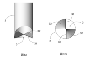
- 3A and 3B are cross-sectional views schematically showing the helical blade 3 of the present invention.
- FIG. 4 is a cross-sectional view schematically showing a device according to a second embodiment of the present invention.
- FIG. 5 is a cross-sectional view schematically showing a device according to a third embodiment of the present invention.
- 6A and 6B are cross-sectional views schematically showing an example of use of the device according to the third embodiment of the present invention.
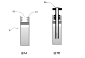
- 7A and 7B are cross-sectional views schematically showing the container of the present invention.
- proximal end portion refers to the operator-side end portion of the device
- distal end portion refers to the tissue-side end portion of the device.
- FIG. 1 is a cross-sectional view schematically showing a device according to a first embodiment of the present invention.
- the device includes a sheath member 1 and a puncture tube 2, and the puncture tube 2 can be inserted into the sheath member 1 so as to freely advance and retract.
- Both the sheath member 1 and the puncture tube 2 are cylindrical bodies.
- the sheath member 1 has a first threaded portion 11 projecting from the inner surface on the proximal end side, and the distal end portion 12 of the sheath member 1 is inclined with respect to a plane perpendicular to the long axis of the sheath member 1.
- the puncture tube 2 has a second threaded portion 21 projecting from the outer surface on the proximal end side and threadedly engaged with the first threaded portion 11.
- the length of the first threaded portion 11 is substantially the same as the length of the second threaded portion 21, and the length of the sheath member 1 on the distal end side from the first threaded portion 11 is the second threaded portion of the puncture tube 2.
- the length is substantially the same as the length on the tip side from the joint portion 21.
- a spiral blade 3 is projected on the inner surface of the distal end portion 22 of the puncture tube 2, and an operation portion 24 is provided on the proximal end portion 23 of the puncture tube 2.
- the outer diameter of the base end side of the sheath member 1 on which the first screwing portion 11 is protruded is larger than the outer diameter of the sheath member 1 on the distal end side than the first screwing portion 11, and the stopper 13 is formed by a step of this outer diameter. Is forming.
- the inner diameter of the sheath member 1 on the distal end side from the first screwing portion 11 is smaller than the outer diameter of the second screwing portion 21 of the puncture tube 2, and the second screwing portion 21 is the first screwing of the sheath member 1. It is designed not to be screwed into the tip side from the portion 11.
- FIG. 2A to 2D are cross-sectional views schematically showing a usage example of the device according to the first embodiment of the present invention.
- the distal end portion 12 of the sheath member 1 is punctured into the application site, the incision and the tissue are cut out, and the tissue is taken into the inside of the sheath member 1 (FIG. 2A). Since the sheath member 1 has the stopper 13, problems such as the sheath member 1 inadvertently entering the application site are unlikely to occur.
- the sheath member 1 may have a scale on the outer surface so that the puncture depth at the application site of the sheath member 1 can be confirmed.
- the puncture tube 2 is inserted into the sheath member 1, the second screwing portion 21 of the puncture tube 2 and the first screwing portion 11 of the sheath member 1 are screwed together, and the operation portion 24 is operated.
- the puncture tube 2 is rotated (FIG. 2B).
- the puncture tube 2 is screwed in the distal direction (downward arrow direction) of the sheath member 1 while rotating, and the spiral blade 3 of the puncture tube 2 takes the inside of the puncture tube 2 while chopping the tissue in the sheath member 1. .
- the screwing of the puncture tube 2 stops halfway (FIG. 2C). That is, even if the operation unit 24 is further operated, the puncture tube 2 does not rotate and does not advance further.
- the sheath member 1 is pulled out together with the puncture tube 2 in the direction of the upward arrow, or the puncture tube 2 is rotated in the direction opposite to the previous direction and pulled out in the direction of the upward arrow (FIG. 2D).
- the sheath member 1 and the puncture tube 2 are integrally rotated in advance, and the tissue in the puncture tube 2 is surely cut from the application site by the spiral blade 3. Also good.
- the screwing of the sheath member 1 and the puncture tube 2 may be configured such that when the puncture tube 2 is screwed to a certain position in the sheath member 1, the sheath member 1 starts spinning and does not advance further in the axial direction. In this case, the tissue can be cut by rotating the puncture tube 2 in the sheath member 1, and the tissue can be collected less invasively than the case where the tissue is cut by rotating together with the sheath member 1.
- the device of the present invention limits the advancement and retraction of the puncture tube 2 by screwing, problems such as the puncture tube 2 entering the application site inadvertently due to carelessness of the operator are unlikely to occur. Further, since the advance / retreat distance of the puncture tube 2 is determined by the rotation distance of the operation unit 24, for example, the amount of tissue collected can be quantitatively adjusted by the rotation number of the operation unit 24. Moreover, since the stopper 13 is formed on the outer surface of the sheath member 1 of the present invention, when the sheath member 1 is punctured into the application site, problems such as the sheath member 1 entering the application site are unlikely to occur. .
- the puncture tube 2 of the present invention is a cylindrical body, a sufficient amount of tissue can be taken inside the puncture tube 2. And since the helical blade 3 is protrudingly provided on the inner surface, the puncture tube 2 can advance while rotating the application site, and the tissue can be cut into small pieces. Further, the spiral blade 3 functions as a lid at the distal end portion 22 of the puncture tube 2, and when the sheath member 1 and / or the puncture tube 2 is pulled out with the tissue taken into the puncture tube 2, It is possible to prevent the puncture tube 2 from falling off from the distal end portion 22.
- FIG. 3A and 3B are partial sectional views schematically showing the helical blade 3 of the present invention.
- the spiral blade 3 is two plate-like members 32 having a blade 31 at the tip, which is inclined with respect to a plane perpendicular to the long axis of the puncture tube 2.
- the blade 31 is disposed so as to be inclined with respect to a plane perpendicular to the long axis of the puncture tube 2, and can enter the surface of the application site from an oblique direction and proceed to chop the tissue.
- the spiral blade 3 protrudes from the inner surface of the distal end portion of the puncture tube 2, and the axial length of the spiral blade 3 is shorter than the axial length of the puncture tube 2.
- the spiral blade 3 is not provided on the proximal end side from the distal end portion of the puncture tube 2, and does not get in the way when the tissue taken into the puncture tube 2 is taken out.
- the spiral blade 3 is fixed to the inner surface of the puncture tube 2 and the support does not occupy the volume of the puncture tube 2 unlike an auger screw, so that a larger amount of tissue can be taken in accordingly.
- FIG. 3B is a view of the puncture tube 2 with the spiral blade 3 protruding from the axial direction.
- the plate-like member 32 has a fan shape with an angle of 90 degrees when viewed from the axial direction, and the two plate-like members 32 project from the opposed positions on the inner surface of the puncture tube 2. That is, the two plate-like members 32 are arranged so as to draw a double helix in the puncture tube 2, and the tissue can be further cut into pieces. Further, the two blades 31 of the two plate-like members 32 are arranged so as to cross the diameter of the puncture tube 2, and when the puncture tube 2 is rotated and inserted into the application site, the spiral blade 3 is Easy to get into the organization. Furthermore, the tissue taken into the puncture tube 2 can be more reliably held by the two plate-like members 32 facing each other.
- the device according to the first embodiment of the present invention achieves minimally invasiveness because the tissue can be collected quantitatively by a single operation without depending on the operator's technique. be able to.
- the sheath member 1 is not limited to the above-described embodiment, and various modifications can be made.
- the stopper 13 of the sheath member 1 is not limited to the one using the step as described above, and can be fixed to the outer surface of the sheath member 1 and can be slid in the axial direction of the sheath member 1 (see FIG. (Not shown) may be provided. Thereby, quantitative tissue collection can be achieved by sliding the hook-shaped portion according to the scale of the outer surface of the sheath member 1 as described above.
- the helical pitch of the helical blade 3 may be the same as the screwing pitch between the puncture tube 2 and the sheath member 1. Thereby, destruction of the structure
- the angle seen from the axial direction of the member 32 constituting the spiral blade 3 is not limited to 90 degrees, and can be freely set between 1 and 360 degrees, or 360 degrees or more. That is, the spiral blade 3 may be a thread-like blade, a fan-shaped blade, or a spiral blade of 360 degrees or more.
- the number of members 32 is not limited to two, and can be freely set, for example, 1 to 10 sheets. Furthermore, the separation effect of the tissue may be enhanced by making the protruding height in the center direction of the spiral blade 3 larger than the radius of the puncture tube 2.
- FIG. 4 is a cross-sectional view schematically showing a device according to a second embodiment of the present invention.
- the same components as those of the device according to the first embodiment are denoted by the same reference numerals, and the description thereof is omitted.
- the puncture tube 2A includes an inner cylindrical body 5 (the center in the figure) and an outer cylindrical body 4 (the left side in the figure).
- the inner cylindrical body 5 is inserted through the outer cylindrical body 4 so as to be able to advance and retreat (right side in the figure).
- the outer cylindrical body 4 has an opening 43 on the proximal end side, and the inner cylindrical body 5 can be inserted from the proximal end side of the outer cylindrical body 4.
- the inner cylindrical body 5 has a spiral blade 3 protruding from the inner surface, and the outer cylindrical body 4 has a threaded portion 41 protruding from the outer surface.
- the first screwing portion 11 (not shown) of the sheath member 1 (not shown) is screwed into the screwing portion 41 of the outer cylindrical body 4, and the tissue is the inner cylindrical body 5. Taken inside.
- a grip portion 51 is provided on the proximal end side of the inner cylindrical body 5, and the outer diameter of the grip portion 51 is larger than the inner diameter of the outer cylindrical body 4.
- the operator can grip the grip 51 and slide the inner cylindrical body 5 within the outer cylindrical body 4, but the entry of the grip 51 stops at the base end side of the outer cylindrical body 4. .
- the grip 51 can be detachably fixed to the operation unit 44 of the outer cylindrical body 4, and the outer cylindrical body 4 and the inner cylindrical body 5 can be rotated integrally.
- the inner cylindrical body 5 is provided with a thin portion T extending in the axial direction.
- the inner cylindrical body 5 is pulled out from the outer cylindrical body 4, and the tissue is pushed out to the distal end side by inserting a rod-like body or air from the proximal end side of the inner cylindrical body 5, or the inner cylindrical body
- the shape 5 can be easily taken out by vertically dividing it along the thin portion T.
- the inner cylindrical body 5 is made of a light transmissive material and has a scale 52 on the outer surface. Therefore, the operator can check the amount of tissue taken into the inner cylindrical body 5 from the outside of the inner cylindrical body 5.
- the inner cylindrical body 5 is returned into the outer cylindrical body 4, and the puncture cylinder 2A is rotated again within the sheath member 1 to take in an insufficient amount of tissue. Can do.
- the device according to the second embodiment of the present invention achieves minimally invasiveness because the tissue can be collected quantitatively by a single operation without depending on the operator's technique. be able to.
- the puncture tube 2A is not limited to the above-described embodiment, and various modifications can be taken.
- both the inner cylindrical body 5 and the outer cylindrical body 4 may be made of a light-transmitting material so that the amount of tissue collected can be confirmed simply by removing the puncture cylinder 2A from the sheath member 1.
- the sheath member 1 may also be made of a light-transmitting material so that the amount of tissue collected can be confirmed without removing the puncture tube 2A from the sheath member 1.
- FIG. 5 is a cross-sectional view schematically showing a device according to a third embodiment of the present invention.
- the same components as those of the device according to the first embodiment and the second embodiment are denoted by the same reference numerals and the description thereof is omitted.
- the length of the sheath member 1A (left side in the figure) on the distal end side from the first threaded part 11 is shorter than the length on the distal side from the second threaded part 21 in the puncture tube 2B (center in the figure).
- the distal end portion 12 ⁇ / b> A of the sheath member 1 is parallel to a plane perpendicular to the long axis of the sheath member 1.
- the blade 12 is not provided with a blade at the distal end portion 12A of the sheath member 1, and is designed so as not to be stabbed even if the distal end portion 12A of the sheath member 1 is pressed against the application site.
- the distal end portion 22B of the puncture tube 2B is parallel to a plane perpendicular to the long axis of the puncture tube 2B.
- the inner surface of the puncture tube 2B is not provided with a spiral blade, and instead, the blade 22C is provided at the lower end of the puncture tube 2B, that is, at the distal end portion 22B. Therefore, the distal end portion 22B of the puncture tube 2B can be punctured into the application site, incision and tissue cutting can be performed, and the tissue can be taken inside the puncture tube 2B.
- An opening 25 is provided at the proximal end 23 of the puncture tube 2B.
- FIG. 6A and 6B are cross-sectional views showing examples of use of the device according to the third embodiment of the present invention.
- the tip 12A of the sheath member 1A is placed on the surface of the application site (FIG. 6A). Since the end portion 12A is not provided with a blade, the sheath member 1A does not pierce the application site.
- the puncture tube 2B is inserted into the sheath member 1A, the second screwing portion 21 of the puncture tube 2B and the first screwing portion 11 of the sheath member 1A are screwed together, and the operation unit 24 is operated. The puncture tube 2B is rotated.
- the blade 22C provided at the distal end portion 22B of the puncture tube 2B cuts out the surface of the application site to cut out the tissue, and takes the tissue inward (FIG. 6B).
- the inside of the puncture tube 2B is sealed with the opening 25 of the puncture tube 2B closed with a finger or the like, and the tissue is peeled off from the application site by pulling out the puncture tube 2B together with the sheath member 1A. it can.
- the device according to the third embodiment of the present invention achieves minimally invasiveness because the tissue can be collected quantitatively by a single operation without depending on the operator's technique. be able to.
- the puncture tube 2B is not limited to the above embodiment, and various modifications can be made.
- a spiral blade may be projected from the inner surface of the puncture tube 2B.
- the opening 25 can be opened and closed, so that the inside of the puncture tube 2B can be sealed without depending on the operator's technique.
- the puncture tube 2B may include a piston member (not shown) that can be inserted into the opening 25.
- the piston member is slid in the puncture tube 2B, and the tissue taken into the puncture tube 2B is pulled up to the proximal end portion 23 side, or conversely pushed out from the distal end portion 22 side of the puncture tube 2B. Can do.
- FIG. 7A and 7B are cross-sectional views schematically showing the container of the present invention.
- the container 6 is a bottomed cylindrical container and can accommodate a liquid inside.
- a liquid is not limited, and examples thereof include a liquid culture medium, physiological saline, isotonic solution, buffer solution, and cryoprotective solution.
- the container 6 has an opening 62, and a third screwing portion 61 projects from the inside of the opening 62.
- the third screwing portion 61 is the second screwing portion 21 of the puncture tube 2 in the first embodiment, the second screwing portion 41 of the puncture tube 2A in the second embodiment, and the second screwing portion 41 of the puncture tube 2B in the third embodiment.
- the two screwing portions 21 can be screwed. That is, the container 6 can accommodate the puncture tube 2, the puncture tube 2A, and the puncture tube 2B.
- FIG. 7B shows the container 6 containing the puncture tube 2A.
- the puncture tube 2A By screwing the second screwing portion 41 of the puncture tube 2A with the third screwing portion 61 of the container 6, the puncture tube 2A can be securely screwed to the container 6 and the container 6 can be sealed. it can.
- the tissue is taken into the puncture tube 2A, and the tissue is stored in a state of being immersed in the liquid in the container 6.
- the state of the tissue may be confirmed from the outside of the container.
- the blade may be selectively provided at the distal end of the sheath member 1, the distal end of the puncture tube 2, or the distal end of the plate-like member of the puncture tube 2.
- the spiral blade a spiral blade such as that used for an auger screw may be projected on the inner surface of the puncture tube 2, or the spiral blade may be attached to a support column like an auger screw, and the puncture tube 2 It may be designed to be slidable in the axial direction.
- each component can be replaced with any component that can exhibit the same function, or any component can be added.
Landscapes
- Health & Medical Sciences (AREA)
- Life Sciences & Earth Sciences (AREA)
- Surgery (AREA)
- Medical Informatics (AREA)
- Biomedical Technology (AREA)
- Heart & Thoracic Surgery (AREA)
- Engineering & Computer Science (AREA)
- Molecular Biology (AREA)
- Pathology (AREA)
- Animal Behavior & Ethology (AREA)
- General Health & Medical Sciences (AREA)
- Public Health (AREA)
- Veterinary Medicine (AREA)
- Nuclear Medicine, Radiotherapy & Molecular Imaging (AREA)
- Surgical Instruments (AREA)
Abstract
Description
[1]第1螺合部を内面に有する鞘部材、および該鞘部材内を進退自在に挿通され、外面に前記第1螺合部に螺合する第2螺合部を有する、穿刺筒を含み、前記鞘部材および/または前記穿刺筒が先端に刃を有する、組織採取デバイス。
[2]穿刺筒が、該穿刺筒の内面に突設された螺旋状の刃を有する、上記[1]に記載の組織採取デバイス。
[3]鞘部材の外面に目盛りを有する、上記[1]または[2]に記載の組織採取デバイス。
[4]穿刺筒が、外側筒状体、および該外側筒状体内を進退自在に挿通される内側筒状体を含む、上記[1]~[3]のいずれか一つに記載の組織採取デバイス。
[5]内側筒状体が軸方向に延伸する溝を有する、上記[4]に記載の組織採取デバイス。
[6]第2螺合部と螺合する第3螺合部を有する、穿刺筒を収容するための容器をさらに含む、上記[1]~[5]のいずれか一つに記載の組織採取デバイス。
[7]少なくとも一部が光透過性の材料で構成される、上記[1]~[6]のいずれか一つに組織採取デバイス。
まず、本発明の第1実施態様に係るデバイスについて説明する。図1は、本発明の第1実施態様に係るデバイスを概略的に示す、断面図である。デバイスは、鞘部材1および穿刺筒2を含み、穿刺筒2は、鞘部材1内に進退自在に挿通することができる。鞘部材1および穿刺筒2は、共に筒状体である。鞘部材1は、基端側の内面に第1螺合部11が突設されており、鞘部材1の先端部12は、鞘部材1の長軸に対して垂直な面に対して傾斜しており、組織に刺し込むことができる先尖形状の刃として形成されている。穿刺筒2は、基端側の外面に、第1螺合部11と螺合する第2螺合部21が突設されている。第1螺合部11の長さは、第2螺合部21の長さと略同一であり、鞘部材1の第1螺合部11より先端側の長さは、穿刺筒2の第2螺合部21より先端側の長さと略同一である。
次に、本発明の第2実施態様に係るデバイスについて説明する。図4は、本発明の第2実施態様に係るデバイスを概略的に示す、断面図である。なお、以下の説明では、第1実施態様に係るデバイスの構成と同じ部分については、同じ符号を付してそれらの説明は省略する。
次に、本発明の第3実施態様に係るデバイスについて説明する。図5は、本発明の第3実施態様に係るデバイスを概略的に示す、断面図である。なお、以下の説明では、第1実施態様および第2実施態様に係るデバイスの構成と同じ部分については、同じ符号を付してそれらの説明は省略する。
本発明においては、各構成は、同様の機能を発揮し得る任意のものと置換することができ、あるいは、任意の構成を付加することもできる。
2、2A、2B 穿刺筒
3 螺旋状刃
4 外側筒状体
5 内側筒状体
6 容器
Claims (7)
- 第1螺合部を内面に有する鞘部材、および該鞘部材内を進退自在に挿通され、外面に前記第1螺合部に螺合する第2螺合部を有する、穿刺筒を含み、前記鞘部材および/または前記穿刺筒が先端に刃を有する、組織採取デバイス。
- 穿刺筒が、該穿刺筒の内面に突設された螺旋状の刃を有する、請求項1に記載の組織採取デバイス。
- 鞘部材の外面に目盛りを有する、請求項1または2に記載の組織採取デバイス。
- 穿刺筒が、外側筒状体、および該外側筒状体内を進退自在に挿通される内側筒状体を含む、請求項1~3のいずれか一項に記載の組織採取デバイス。
- 内側筒状体が軸方向に延伸する溝を有する、請求項4に記載の組織採取デバイス。
- 第2螺合部と螺合する第3螺合部を有する、穿刺筒を収容するための容器をさらに含む、請求項1~5のいずれか一項に記載の組織採取デバイス。
- 少なくとも一部が光透過性の材料で構成される、請求項1~6のいずれか一項に記載の組織採取デバイス。
Priority Applications (3)
| Application Number | Priority Date | Filing Date | Title |
|---|---|---|---|
| EP17770317.0A EP3406200A4 (en) | 2016-03-23 | 2017-03-23 | TISSUE SAMPLING DEVICE |
| JP2018507391A JP6770059B2 (ja) | 2016-03-23 | 2017-03-23 | 組織採取デバイス |
| US16/137,792 US20190021706A1 (en) | 2016-03-23 | 2018-09-21 | Tissue collection device |
Applications Claiming Priority (2)
| Application Number | Priority Date | Filing Date | Title |
|---|---|---|---|
| JP2016058142 | 2016-03-23 | ||
| JP2016-058142 | 2016-03-23 |
Related Child Applications (1)
| Application Number | Title | Priority Date | Filing Date |
|---|---|---|---|
| US16/137,792 Continuation US20190021706A1 (en) | 2016-03-23 | 2018-09-21 | Tissue collection device |
Publications (1)
| Publication Number | Publication Date |
|---|---|
| WO2017164277A1 true WO2017164277A1 (ja) | 2017-09-28 |
Family
ID=59900268
Family Applications (1)
| Application Number | Title | Priority Date | Filing Date |
|---|---|---|---|
| PCT/JP2017/011624 Ceased WO2017164277A1 (ja) | 2016-03-23 | 2017-03-23 | 組織採取デバイス |
Country Status (4)
| Country | Link |
|---|---|
| US (1) | US20190021706A1 (ja) |
| EP (1) | EP3406200A4 (ja) |
| JP (1) | JP6770059B2 (ja) |
| WO (1) | WO2017164277A1 (ja) |
Cited By (1)
| Publication number | Priority date | Publication date | Assignee | Title |
|---|---|---|---|---|
| US20210093307A1 (en) * | 2019-09-30 | 2021-04-01 | Cook Medical Technologies Llc | Internally barbed biopsy stylet and system |
Families Citing this family (1)
| Publication number | Priority date | Publication date | Assignee | Title |
|---|---|---|---|---|
| US20250235189A1 (en) * | 2024-01-24 | 2025-07-24 | Eddy Pump Corporation | Biopsy device |
Citations (6)
| Publication number | Priority date | Publication date | Assignee | Title |
|---|---|---|---|---|
| JP2000060859A (ja) | 1998-08-19 | 2000-02-29 | Asahi Optical Co Ltd | 細胞組織採取具 |
| JP2012235878A (ja) | 2011-05-11 | 2012-12-06 | Terumo Corp | 生検デバイス |
| WO2014050456A1 (ja) * | 2012-09-27 | 2014-04-03 | テルモ株式会社 | 生検デバイス |
| JP2014113211A (ja) * | 2012-12-06 | 2014-06-26 | National Institute Of Advanced Industrial & Technology | 内視鏡用組織片採取装置 |
| JP2014200410A (ja) * | 2013-04-03 | 2014-10-27 | テルモ株式会社 | 生検デバイス |
| JP2015085141A (ja) | 2013-11-01 | 2015-05-07 | 国立大学法人 千葉大学 | 内視鏡用の穿刺針 |
Family Cites Families (5)
| Publication number | Priority date | Publication date | Assignee | Title |
|---|---|---|---|---|
| US4099518A (en) * | 1976-05-10 | 1978-07-11 | Baylis Shelby M | Biopsy apparatus |
| US6110128A (en) * | 1998-12-11 | 2000-08-29 | Andelin; John B. | Bone marrow biopsy needle and method for using the same |
| EP2117439B1 (en) * | 2007-01-15 | 2012-03-21 | Jacques Phillibert Janssens | Pneumatic device for taking a tissue sample |
| US9402602B2 (en) * | 2013-01-25 | 2016-08-02 | Choon Kee Lee | Tissue sampling apparatus |
| FR3013958B1 (fr) * | 2013-12-03 | 2017-11-03 | Thierry Masseglia | Trocart a biopsie. |
-
2017
- 2017-03-23 WO PCT/JP2017/011624 patent/WO2017164277A1/ja not_active Ceased
- 2017-03-23 JP JP2018507391A patent/JP6770059B2/ja active Active
- 2017-03-23 EP EP17770317.0A patent/EP3406200A4/en not_active Withdrawn
-
2018
- 2018-09-21 US US16/137,792 patent/US20190021706A1/en not_active Abandoned
Patent Citations (6)
| Publication number | Priority date | Publication date | Assignee | Title |
|---|---|---|---|---|
| JP2000060859A (ja) | 1998-08-19 | 2000-02-29 | Asahi Optical Co Ltd | 細胞組織採取具 |
| JP2012235878A (ja) | 2011-05-11 | 2012-12-06 | Terumo Corp | 生検デバイス |
| WO2014050456A1 (ja) * | 2012-09-27 | 2014-04-03 | テルモ株式会社 | 生検デバイス |
| JP2014113211A (ja) * | 2012-12-06 | 2014-06-26 | National Institute Of Advanced Industrial & Technology | 内視鏡用組織片採取装置 |
| JP2014200410A (ja) * | 2013-04-03 | 2014-10-27 | テルモ株式会社 | 生検デバイス |
| JP2015085141A (ja) | 2013-11-01 | 2015-05-07 | 国立大学法人 千葉大学 | 内視鏡用の穿刺針 |
Non-Patent Citations (1)
| Title |
|---|
| See also references of EP3406200A4 |
Cited By (1)
| Publication number | Priority date | Publication date | Assignee | Title |
|---|---|---|---|---|
| US20210093307A1 (en) * | 2019-09-30 | 2021-04-01 | Cook Medical Technologies Llc | Internally barbed biopsy stylet and system |
Also Published As
| Publication number | Publication date |
|---|---|
| US20190021706A1 (en) | 2019-01-24 |
| EP3406200A1 (en) | 2018-11-28 |
| EP3406200A4 (en) | 2019-12-25 |
| JP6770059B2 (ja) | 2020-10-14 |
| JPWO2017164277A1 (ja) | 2019-02-14 |
Similar Documents
| Publication | Publication Date | Title |
|---|---|---|
| CN105310730B (zh) | 可更换的取芯活检针 | |
| CN107773274B (zh) | 螺旋软组织活检针 | |
| US11779316B2 (en) | Biopsy device | |
| US9968337B2 (en) | Coring tissue biopsy needle and method of use | |
| US5660186A (en) | Spiral biopsy stylet | |
| US9572551B2 (en) | Biopsy trocar | |
| US20150141868A1 (en) | Needle biopsy systems and methods | |
| US20090326412A1 (en) | Biopsy Device with Rotating Needle | |
| WO2017180761A1 (en) | Biopsy cutter and methods of use therefor | |
| JP6770059B2 (ja) | 組織採取デバイス | |
| US20140213933A1 (en) | Device for the laparoscopic removal of a superficial cylindrical sample of a human or animal body tissue | |
| US20160081675A1 (en) | Helical driven rotating tissue collection | |
| JP2009034190A (ja) | カニューレ | |
| CN110477963A (zh) | 穿刺活检环锯 | |
| CN202184751U (zh) | 可取样的穿刺装置 | |
| CN219814189U (zh) | 一种旋转式骨组织活检器 | |
| CN219021299U (zh) | 一种椎体骨组织穿刺活检取样器 | |
| EP3415099A1 (en) | Medical muiltiple skin biopsy device | |
| CN215018013U (zh) | 骨髓活检针 | |
| CN120959804A (zh) | 一种骨组织活检取样工具 | |
| CA2902221C (en) | Biopsy device | |
| KR101633589B1 (ko) | 생검 장치 | |
| CN121176964A (zh) | 一种用于脊柱病灶的取活检器械及其操作方法 |
Legal Events
| Date | Code | Title | Description |
|---|---|---|---|
| ENP | Entry into the national phase |
Ref document number: 2018507391 Country of ref document: JP Kind code of ref document: A |
|
| WWE | Wipo information: entry into national phase |
Ref document number: 2017770317 Country of ref document: EP |
|
| ENP | Entry into the national phase |
Ref document number: 2017770317 Country of ref document: EP Effective date: 20180823 |
|
| NENP | Non-entry into the national phase |
Ref country code: DE |
|
| 121 | Ep: the epo has been informed by wipo that ep was designated in this application |
Ref document number: 17770317 Country of ref document: EP Kind code of ref document: A1 |