WO2017164290A1 - マイクロ波加熱装置 - Google Patents
マイクロ波加熱装置 Download PDFInfo
- Publication number
- WO2017164290A1 WO2017164290A1 PCT/JP2017/011664 JP2017011664W WO2017164290A1 WO 2017164290 A1 WO2017164290 A1 WO 2017164290A1 JP 2017011664 W JP2017011664 W JP 2017011664W WO 2017164290 A1 WO2017164290 A1 WO 2017164290A1
- Authority
- WO
- WIPO (PCT)
- Prior art keywords
- microwave
- heating
- reflected wave
- radiation antenna
- heated
- Prior art date
- Legal status (The legal status is an assumption and is not a legal conclusion. Google has not performed a legal analysis and makes no representation as to the accuracy of the status listed.)
- Ceased
Links
Images


Classifications
-
- H—ELECTRICITY
- H05—ELECTRIC TECHNIQUES NOT OTHERWISE PROVIDED FOR
- H05B—ELECTRIC HEATING; ELECTRIC LIGHT SOURCES NOT OTHERWISE PROVIDED FOR; CIRCUIT ARRANGEMENTS FOR ELECTRIC LIGHT SOURCES, IN GENERAL
- H05B6/00—Heating by electric, magnetic or electromagnetic fields
- H05B6/64—Heating using microwaves
- H05B6/66—Circuits
- H05B6/68—Circuits for monitoring or control
- H05B6/687—Circuits for monitoring or control for cooking
-
- F—MECHANICAL ENGINEERING; LIGHTING; HEATING; WEAPONS; BLASTING
- F24—HEATING; RANGES; VENTILATING
- F24C—DOMESTIC STOVES OR RANGES ; DETAILS OF DOMESTIC STOVES OR RANGES, OF GENERAL APPLICATION
- F24C7/00—Stoves or ranges heated by electric energy
- F24C7/02—Stoves or ranges heated by electric energy using microwaves
-
- H—ELECTRICITY
- H01—ELECTRIC ELEMENTS
- H01P—WAVEGUIDES; RESONATORS, LINES, OR OTHER DEVICES OF THE WAVEGUIDE TYPE
- H01P5/00—Coupling devices of the waveguide type
- H01P5/12—Coupling devices having more than two ports
- H01P5/16—Conjugate devices, i.e. devices having at least one port decoupled from one other port
- H01P5/18—Conjugate devices, i.e. devices having at least one port decoupled from one other port consisting of two coupled guides, e.g. directional couplers
- H01P5/184—Conjugate devices, i.e. devices having at least one port decoupled from one other port consisting of two coupled guides, e.g. directional couplers the guides being strip lines or microstrips
-
- H—ELECTRICITY
- H05—ELECTRIC TECHNIQUES NOT OTHERWISE PROVIDED FOR
- H05B—ELECTRIC HEATING; ELECTRIC LIGHT SOURCES NOT OTHERWISE PROVIDED FOR; CIRCUIT ARRANGEMENTS FOR ELECTRIC LIGHT SOURCES, IN GENERAL
- H05B6/00—Heating by electric, magnetic or electromagnetic fields
- H05B6/64—Heating using microwaves
- H05B6/70—Feed lines
- H05B6/705—Feed lines using microwave tuning
-
- H—ELECTRICITY
- H05—ELECTRIC TECHNIQUES NOT OTHERWISE PROVIDED FOR
- H05B—ELECTRIC HEATING; ELECTRIC LIGHT SOURCES NOT OTHERWISE PROVIDED FOR; CIRCUIT ARRANGEMENTS FOR ELECTRIC LIGHT SOURCES, IN GENERAL
- H05B6/00—Heating by electric, magnetic or electromagnetic fields
- H05B6/64—Heating using microwaves
- H05B6/70—Feed lines
- H05B6/707—Feed lines using waveguides
-
- H—ELECTRICITY
- H05—ELECTRIC TECHNIQUES NOT OTHERWISE PROVIDED FOR
- H05B—ELECTRIC HEATING; ELECTRIC LIGHT SOURCES NOT OTHERWISE PROVIDED FOR; CIRCUIT ARRANGEMENTS FOR ELECTRIC LIGHT SOURCES, IN GENERAL
- H05B6/00—Heating by electric, magnetic or electromagnetic fields
- H05B6/64—Heating using microwaves
- H05B6/72—Radiators or antennas
- H05B6/725—Rotatable antennas
-
- Y—GENERAL TAGGING OF NEW TECHNOLOGICAL DEVELOPMENTS; GENERAL TAGGING OF CROSS-SECTIONAL TECHNOLOGIES SPANNING OVER SEVERAL SECTIONS OF THE IPC; TECHNICAL SUBJECTS COVERED BY FORMER USPC CROSS-REFERENCE ART COLLECTIONS [XRACs] AND DIGESTS
- Y02—TECHNOLOGIES OR APPLICATIONS FOR MITIGATION OR ADAPTATION AGAINST CLIMATE CHANGE
- Y02B—CLIMATE CHANGE MITIGATION TECHNOLOGIES RELATED TO BUILDINGS, e.g. HOUSING, HOUSE APPLIANCES OR RELATED END-USER APPLICATIONS
- Y02B40/00—Technologies aiming at improving the efficiency of home appliances, e.g. induction cooking or efficient technologies for refrigerators, freezers or dish washers
Definitions
- the present invention relates to a microwave heating apparatus that heats an object to be heated with a microwave and controls heating by detecting a part of the microwave propagating in a waveguide.
- a microwave oven is known as a typical microwave heating apparatus.
- a general microwave oven uses a magnetron as a microwave generator. The microwave oven transmits the microwave radiated from the magnetron to the heating chamber through the waveguide. And the to-be-heated material (foodstuff) in a heating chamber is heated with the transmitted microwave.
- the microwave oven is required to be heated as uniformly as possible so as not to cause uneven heating of the object to be heated. Therefore, at present, there are microwave ovens equipped with a turntable method for rotating an object to be heated itself, a rotating antenna method in which a rotatable antenna is disposed in a portion that radiates microwaves from a waveguide into a heating chamber, and the like.
- microwaves incident waves or traveling waves
- microwaves reflected waves
- the reflected wave varies depending on the shape, material, and position of the object to be heated.
- the reflected wave also changes depending on the direction of the turntable or antenna described above. That is, in order to uniformly heat the object to be heated, it is necessary to grasp changes in incident waves and reflected waves.
- the directional coupler As a method for monitoring the incident wave and the reflected wave in the waveguide.
- the directional coupler has a function of separating incident waves and reflected waves mixed in the waveguide, and a certain amount of attenuation (for example, 30 dB) so as not to affect the microwave transmission in the waveguide due to mounting. It is necessary to make it. As a result, the size of the directional coupler is increased. For this reason, many microwave ovens that are assumed to be used in ordinary homes are not equipped with directional couplers.
- the microwave heating apparatus described in Patent Document 2 calculates a value related to reflectance (reflection coefficient ⁇ or voltage standing wave ratio ⁇ ) from an incident wave and a reflected wave. Next, based on the obtained values, three rotational positions are selected from the lower value when the rotating antenna makes one revolution. Then, the rotating antenna is stopped for 10 seconds at the selected rotational position. In other words, a value with a low reflectivity results in less microwave reflection. Therefore, the object to be heated can be efficiently heated by stopping the rotating antenna in the direction of the rotational position.
- the rotation of the rotating antenna is aimed at uniform heating.
- the rotation stop control of the rotating antenna is contrary to the original purpose. That is, in order to avoid the deterioration of the uniform heating performance, further ingenuity is required.
- the present invention provides a microwave heating apparatus capable of both improving heating efficiency and maintaining uniform heating.
- the microwave heating device of the present invention includes a heating chamber that houses an object to be heated, a microwave generation unit that generates a microwave to be supplied to the heating chamber, and a microwave generated by the microwave generation unit. And a radiation antenna that radiates microwaves transmitted through the waveguide to the heating chamber, and a rotation drive unit that rotates the radiation antenna. Further, the microwave heating device includes a reflected wave detection unit that detects at least a part of the reflected wave in the waveguide, and a radiation antenna that controls the rotation driving unit based on the reflected wave detection amount detected by the reflected wave detection unit. The control part which controls the direction of is provided. The control unit has a configuration for controlling the rotation driving unit so as to stop the rotation of the radiation antenna in a direction in which the reflected wave detection amount is minimum and in a direction different from the minimum direction.
- the rotation of the radiation antenna is stopped in the direction in which the reflected wave detection amount is minimized.
- the heating time which heats a to-be-heated material on the most efficient heating conditions is extended. Therefore, the heating efficiency is further improved as compared with the case where the radiation antenna is heated while being rotated at a constant rotation.
- the rotation of the radiation antenna is stopped in a direction different from the minimum direction. At this time, in addition to the heating unevenness that occurs during the stop in the direction in which the detected amount of the reflected wave is minimized, the heating unevenness due to the microwave radiation from different directions occurs.
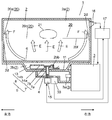
- FIG. 1 is a cross-sectional view showing a schematic configuration of the microwave heating apparatus according to the first embodiment of the present invention.
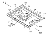
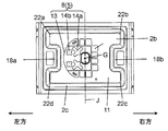
- FIG. 2A is a perspective view showing a power feeding chamber of a heating unit in the microwave heating apparatus of the embodiment.
- FIG. 2B is a plan view showing a power feeding chamber of a heating unit in the microwave heating apparatus of the embodiment.
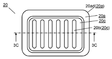
- FIG. 3A is a plan view of a grill pan used in the grill mode.
- FIG. 3B is a side view of the grill pan used in the grill mode.
- FIG. 3C is a longitudinal sectional view of a grill pan used in the grill mode.
- FIG. 4 is a diagram showing the characteristics of the reflected wave detection amount depending on the direction of the radiation antenna of the microwave heating apparatus in the same embodiment.
- FIG. 4 is a diagram showing the characteristics of the reflected wave detection amount depending on the direction of the radiation antenna of the microwave heating apparatus in the same embodiment.
- FIG. 5 is a diagram for explaining the relationship between the direction of the radiation antenna of the microwave heating apparatus and the heat distribution of the grill pan in the same embodiment.
- FIG. 6 is a front perspective view showing a schematic configuration of the microwave heating apparatus according to the second embodiment of the present invention with the door removed.
- FIG. 7 is a diagram illustrating the characteristics of the incident wave detection amount, the reflected wave detection amount, and the absorption amount according to the direction of the radiation antenna according to the embodiment.
- FIG. 8 is a diagram for explaining the relationship between the direction of the radiating antenna and the heating portion according to the embodiment.
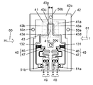
- FIG. 9 is a perspective view of the directional coupler according to the embodiment of the present invention.
- FIG. 10 is a perspective view showing the printed circuit board in the directional coupler of FIG. FIG.
- FIG. 11 is a configuration diagram illustrating a cross opening of the directional coupler of FIG. 9.
- FIG. 12 is a circuit configuration diagram of a printed circuit board of the directional coupler of FIG.
- FIG. 13 is a polar coordinate diagram showing the output characteristics of the reflected wave detector in the directional coupler of FIG.
- FIG. 14 is a polar coordinate diagram showing output characteristics of the reflected wave detector in another configuration of the directional coupler of FIG.
- FIG. 15 is a polar coordinate diagram showing output characteristics of the traveling wave power detector in the directional coupler of FIG.
- FIG. 1 is a cross-sectional view showing a schematic configuration of a microwave oven which is an example of a microwave heating apparatus according to Embodiment 1 of the present invention. Specifically, FIG. 1 is a cross-sectional view of the microwave oven 1 as seen from the front side.
- the left-right direction of the microwave oven 1 means the left-right direction in FIG.
- the front-rear direction of the microwave oven 1 means a direction perpendicular to the paper surface in FIG. 1 and connecting the front side and the back side of the apparatus.
- a microwave oven 1 includes a heating chamber space 2 constituted by an outer shell, a magnetron 3, a waveguide 4, a radiation antenna 5, a mounting table 6, and the like.
- the heating chamber space 2 includes a heating chamber 2 a that forms a space above the mounting table 6 and a power supply chamber 2 b that forms a space below the mounting table 6.
- the magnetron 3 is an example of a microwave generation unit that generates a microwave.
- the waveguide 4 is an example of a transmission unit that transmits the microwave generated by the magnetron 3 to the heating chamber space 2.
- the radiating antenna 5 is an example of a waveguide structure antenna.
- the radiating antenna 5 is configured to radiate the microwave in the waveguide 4 into the heating chamber space 2, and is provided in the space of the power feeding chamber 2 b below the mounting table 6.
- the mounting table 6 is disposed in the heating chamber space 2 and has a flat surface on which food that is the object to be heated 21 is placed.
- the mounting table 6 is arranged so as to cover the entire upper part of the power supply chamber 2b where the radiation antenna 5 is provided. Thereby, the mounting table 6 closes the power supply chamber 2b so that the radiation antenna 5 is not exposed in the heating chamber 2a, and constitutes the bottom surface of the heating chamber 2a.
- the upper surface (mounting surface) configuration of the flat mounting table 6 it is easy for the user to put food in and out and to wipe off dirt attached to the mounting table 6.
- the mounting table 6 is made of a material such as glass or ceramics that easily transmits microwaves. Thereby, the microwave radiated
- the radiation antenna 5 has a coupling portion 7 and a waveguide structure portion 8 joined to the coupling portion 7.
- the coupling unit 7 extracts the microwave radiated from the magnetron 3 into the waveguide 4 to the waveguide structure unit 8.
- the waveguide structure unit 8 is configured by, for example, a box-shaped waveguide structure, and guides the microwave extracted by the coupling unit 7 into the heating chamber 2a.
- the connecting portion 7 is composed of a connecting shaft 7a and a flange 7b.
- the coupling shaft 7a is connected to a motor 15 that is a rotation drive unit.
- the waveguide structure unit 8 is rotationally controlled via a coupling shaft 7 a of the coupling unit 7 connected to the motor 15 by a control signal from the control unit 17 described later. That is, the radiating antenna 5 is rotationally driven by the motor 15 around the coupling shaft 7a of the coupling unit 7, and the stop position, the rotation period, the rotation speed, and the like are controlled.
- the coupling portion 7 is formed of a metal such as an aluminum plated steel plate.
- a connection portion of the motor 15 connected to the coupling portion 7 is formed of, for example, a fluororesin.
- the coupling shaft 7a of the coupling portion 7 is disposed through the opening 2bb that communicates the waveguide 4 and the power feeding chamber 2b.
- the coupling shaft 7a has a predetermined gap, for example, a gap of 5 mm or more, with the through-opening 2bb in order to avoid a danger such as a spark with the through-opening 2bb.
- the coupling shaft 7 a can guide the microwave from the waveguide 4 to the waveguide structure portion 8 of the radiation antenna 5 with high efficiency. In other words, if there is not enough clearance, if sparks occur, a huge amount of power is consumed for the energy of discharge.
- emitted in a warehouse falls extremely and the efficiency which heats a to-be-heated material falls.
- the gap is narrow, even if no spark is generated, the loss of the conductor portion increases and heat is generated, and electric power is consumed for the energy of the heat generation. Therefore, the electric power radiated
- the gap of 5 mm is set assuming a case of a microwave oven that is a general microwave heating device having a maximum output of about 1000 W, for example. Therefore, it goes without saying that if the output level changes, the size of the gap changes.
- the waveguide structure 8 of the radiating antenna 5 mainly includes a tip opening 13 and a plurality of openings 14a and 14b that radiate microwaves.
- the tip opening portion 13 radiates microwaves in a predetermined direction.
- the radiation direction (orientation) of the microwave radiated from the radiation antenna 5 is changed by the rotation of the coupling portion 7 of the radiation antenna 5 connected to the motor 15.
- the microwave oven 1 is equipped with the infrared sensor 16 above the side surface of the heating chamber 2a.
- the infrared sensor 16 divides the heating chamber 2a into a plurality of regions and detects the internal temperature of each region.
- the infrared sensor 16 transmits the detected detection signal (detection result) to the control unit 17.
- the directional coupler 30 is attached to the waveguide 4 and constitutes a reflected wave detection unit in the present embodiment.
- the directional coupler 30 detects the incident wave detection amount and the reflected wave detection amount of the microwave transmitted through the waveguide 4, and transmits the detected detection signal to the control unit 17.
- the incident wave detection amount is detected by a detection signal corresponding to the incident wave (or traveling wave) of the microwave transmitted from the magnetron 3 side toward the radiation antenna 5 side.
- the detected amount of the reflected wave is detected by a detection signal corresponding to the reflected wave of the microwave returning from the radiation antenna 5 side to the magnetron 3 side.
- the control unit 17 performs oscillation control of the magnetron 3 and rotation control of the motor 15 based on the detection signals from the infrared sensor 16 and the directional coupler 30 described above.
- FIG. 1 shows a state in which the grill plate 20 is disposed above the mounting table 6 and the object to be heated 21 is mounted on the grill plate 20.
- the grill pan 20 is placed on the side wall 2d of the heating chamber 2a.
- the grill pan 20 is placed on rails (not shown) formed in the left and right side walls 2d of the heating chamber 2a and extending in the front-rear direction.
- the grill pan 20 is disposed at a position above the mounting table 6 constituting the bottom surface of the heating chamber 2a in the heating chamber 2a.
- the rail may be provided in a plurality of stages (for example, an upper stage, a middle stage, and a lower stage) in the vertical direction on the left and right side walls 2d of the heating chamber 2a.
- positions the grill pan 20 becomes adjustable in multiple steps.
- the microwave oven 1 which is an example of the microwave heating apparatus of the present embodiment is configured.
- FIG. 2A is a perspective view showing a power feeding chamber 2b of the heating chamber space 2 where the radiation antenna 5 is provided.
- FIG. 2B is a plan view showing the power supply chamber 2b of FIG. 2A.
- FIG. 2A shows a bottom surface portion of the heating chamber space 2 from which the mounting table 6 is removed.
- a radiation antenna 5 is provided in the feeding chamber 2b.
- the rotation center G of the coupling shaft 7a is arranged at a position substantially at the center (including the center) in the front-rear direction and the left-right direction of the power supply chamber 2b. That is, the rotation center G is disposed at a position substantially directly below (including immediately below) the center in the front-rear direction and the left-right direction of the mounting table 6 that is the bottom surface of the heating chamber 2a.
- the feeding space is configured by the bottom wall 11 of the feeding chamber 2 b and the lower surface of the mounting table 6.
- the feeding space is formed in a symmetrical shape with respect to a center line J (see FIG. 2B) extending in the front-rear direction of the feeding chamber 2b including the rotation center G of the coupling portion 7.
- the feeding chamber 2b has projecting portions 18a and 18b that project from the bottom wall 11 toward the feeding space.
- the protrusion 18a protrudes from the bottom wall 11 and is formed on the left side wall 2c.
- the protrusion 18b protrudes from the bottom wall 11 and is formed on the right side wall 2c.
- the magnetron 3 is disposed below the protrusion 18b. That is, the protrusion 18 b is provided for the purpose of securing the arrangement space for the magnetron 3.
- the microwave radiated from the output end 3a (see FIG. 1) of the magnetron 3 is transmitted through the waveguide 4 arranged immediately below the power supply chamber 2b.
- the transmitted microwave is guided to the waveguide structure portion 8 through the coupling portion 7 of the radiation antenna 5.
- the microwave is radiated into the power feeding chamber 2b through the open end portion 13 and the openings 14a and 14b formed in the waveguide structure portion 8 of the radiation antenna 5.
- the side wall 2c forming the side surface of the power supply space of the power supply chamber 2b is formed as an inclined surface.
- the inclined surface is formed to be inclined so as to spread obliquely upward, that is, to the outside toward the heating chamber 2a. Due to the inclined surface of the side wall 2c, for example, microwaves radiated in the horizontal direction from the distal end opening portion 13 of the radiation antenna 5 are reflected toward the upper heating chamber 2a.
- the power feeding chamber 2b is formed in a substantially rectangular shape in plan view, and a side wall 2c including projecting portions 18a and 18b projecting from the bottom wall 11 is formed on the short side of the rectangular shape (left and right sides in FIG. 2B).
- the four corners of the power supply chamber 2b correspond to the corners 22a, 22b, 22c, and 22d of the power supply chamber 2b. That is, the protrusion 18a is formed between the corner 22a and the corner 22d, and the protrusion 18b is formed between the corner 22b and the corner 22c of the power supply chamber 2b.
- the power supply chamber 2b of the microwave oven 1 is configured.
- FIG. 3A is a plan view of the grill pan 20 as viewed from above.
- FIG. 3B is a side view of the grill pan 20 as viewed from the side.
- 3C is a cross-sectional view taken along line 3C-3C in FIG. 3A.
- the grill pan 20 includes, for example, a frame-shaped peripheral portion 20a, a plate 20c, an insulating portion 20d, and the like.
- the plate 20c is formed inside the peripheral portion 20a and has a plurality of grooves 20b having a predetermined depth (not shown in FIG. 3C) formed in parallel.
- the insulating part 20d is provided below the peripheral part 20a.
- the object to be heated 21 is placed on the plate 20c of the grill pan 20, placed in the heating chamber 2a, and the object to be heated 21 is heated.
- the grill pan 20 is disposed in the heating chamber 2a with the rails provided on the left and right side walls 2d of the heating chamber 2a in contact with the insulating portion 20d.
- the plate 20c includes a microwave absorption heating element 20e (for example, ferrite) on the back surface side (mounting table 6 side).
- the back surface of the plate 20c constitutes the bottom surface 20f of the grill pan 20.
- the grill pan 20 is configured.
- the peripheral portion 20a and the plate 20c of the grill pan 20 are formed of a material that does not transmit microwaves (for example, iron or aluminum).
- the insulating portion 20d is formed of an insulating material (for example, PPS resin) that transmits microwaves.
- the insulating part 20d insulates the grill pan 20 from the side wall 2d of the heating chamber 2a.
- the microwave radiated from the radiating antenna 5 reaches the bottom surface 20f of the grill pan 20 having the above-described configuration as indicated by an arrow E in FIG.
- the reached microwave is absorbed by the microwave absorption heating element 20e provided on the bottom surface 20f, and the microwave absorption heating element 20e generates heat.
- the generated heat heats the bottom surface 20f of the grill pan 20 by heat transfer.
- the to-be-heated object 21 on the plate 20c of the grill pan 20 is indirectly heated by the microwave.
- the peripheral portion 20a and the plate 20c of the grill pan 20 are made of a material that does not transmit microwaves. Therefore, the heated object 21 is not heated by the permeation of microwaves through the peripheral portion 20a of the grill pan 20 and the plate 20c.
- a gap through which microwaves can pass is formed between the grill pan 20 and the side wall 2d of the heating chamber 2a.
- the rail provided on the side wall 2d of the heating chamber 2a is disposed in contact with the insulating portion 20d of the grill pan 20.
- the insulating part 20d is formed of PPS resin or the like that transmits microwaves. Therefore, microwaves can be transmitted from the grill pan 20 and the left and right side walls 2d of the heating chamber 2a via the insulating portion 20d.
- a door made of, for example, a glass plate, which can be opened and closed at the front opening of the heating chamber 2a, is provided in front of the grill pan 20.
- the door is composed of a conductor portion made of a punching metal or the like for shielding radio waves on the outside, and a glass plate on the inside so as not to let the heat in the cabinet escape and to easily wipe off dirt. Therefore, a part of the microwave radiated from the radiating antenna 5 is transmitted through the front glass plate of the grill pan 20 and reflected by the punching metal, and is radiated into the heating chamber 2 a above the grill pan 20.
- unevenness or the like may be formed on the side wall 2d of the heating chamber 2a in the rearward direction of the grill pan 20, for example. In this case, microwaves are radiated into the heating chamber 2 a above the grill pan 20 from the uneven gap.
- the corner portion 20ad of the peripheral portion 20a of the grill pan 20 is formed in, for example, an arc shape as shown in FIG. 3A. Therefore, a gap is formed between the corner portion 20ad and the corner portion of the heating chamber 2a formed of a quadrangle or the like. Due to this gap, microwaves are radiated into the heating chamber 2 a above the grill pan 20.
- the arrow F in FIG. 1 is placed in the space of the heating chamber 2a above the grill plate 20 where the article to be heated 21 is disposed through the gap between the grill plate 20 and the side wall 2d of the heating chamber 2a.
- a flow through which the microwave shown in FIG. The heated object 21 is directly heated by this microwave flow.
- the microwave flow indicated by the arrow E for indirectly heating the object to be heated 21 and the object to be heated 21 are directly connected.
- Two streams are formed, the microwave stream indicated by the arrow F that heats to. Therefore, in the grill mode, the whole object to be heated 21 is heated by the microwaves radiated from each direction by the two microwave flows.
- the object to be heated 21 is heated directly and indirectly by microwaves.
- the rotation control of the radiating antenna 5 is executed based on the detection signal from the directional coupler 30 found by the inventors of the present application, in particular, the reflected wave detection amount.
- the inventors of the present application have conducted intensive studies in order to perform more appropriate heating control according to the state of the article 21 to be heated.
- the inventors have conducted intensive studies on the control of the grill mode in which grill heating is performed.
- both improvement in heating efficiency and uniform heating of the object to be heated 21 can be realized by controlling the direction (rotation angle) of the radiation antenna 5 that radiates microwaves.
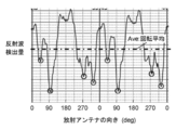
- FIG. 4 is a diagram showing the characteristics of the reflected wave detection amount detected by the directional coupler 30 depending on the direction of the rotating radiation antenna 5 in the configuration of the microwave oven 1 described with reference to FIGS. 1 to 3C.
- the horizontal axis of FIG. 4 represents the direction of the radiation antenna 5, that is, the direction (rotation angle) of the tip opening portion 13.
- the direction (angle) in which the front end opening portion 13 of the radiation antenna 5 faces rearward (opposite the door side) when facing the door of the microwave oven 1 is illustrated as 0 °.
- the rotation angle of the radiation antenna 5 that minimizes the amount of reflected wave detection is 90 °. Focusing on the small value of the reflected wave detection amount, the reflected wave detection amount is small in the order of 90 °, 315 °, 270 °, and 45 ° rotation angles. The values of these reflected wave detection amounts are smaller than the rotation average Ave indicated by the alternate long and short dash line in the figure.
- the inventors of the present application further studied the relationship between the direction (rotation angle) of the tip opening portion 13 of the radiating antenna 5 and the heat distribution in the actual grill pan in order to realize uniform heating. The result is shown in FIG.
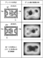
- FIG. 5 is a diagram for explaining the relationship between the direction of the radiating antenna of the microwave heating apparatus and the heat distribution of the grill pan in the same embodiment.
- the distance between the radiation antenna 5 and the grill pan 20 is increased.
- the microwave radiated in the direction in which the tip open portion 13 faces is reflected by the protruding portions 18a and 18b, the side wall 2d of the heating chamber space 2, and the like.
- the concentration of microwaves is determined by the inclination angle of the facing surface to which the tip opening portion 13 of the radiation antenna 5 faces, the shape of the heating chamber space 2, the height position of the grill pan 20, and the like. That is, in the case of the configuration in which the grill pan 20 is arranged in the upper stage, first, the microwave radiated from the tip opening portion 13 causes the first reflection according to the inclination angle of the facing surface. Next, the second reflection occurs at the side wall 2d of the heating chamber space 2. As a result, it is estimated that the microwaves are concentrated on the opposite side of the grill pan 20 disposed in the upper stage. Therefore, when the grill pan 20 is disposed at the middle and lower positions, for example, it is estimated that the microwaves are concentrated on the center of the grill pan 20 in the middle row and on the side facing the tip opening portion 13 in the lower row.
- the inventors of the present application paid attention to the fact that, from the results shown in FIG. 5, the heat distribution of the radiation antenna 5 having a rotation angle of 90 ° and a direction of 270 ° different from 90 ° is almost symmetrical.
- the heating efficiency is better at the rotation angle of 90 ° at which the reflected wave detection amount is the minimum, as shown in the upper right diagram of FIG. 5, the dark region, that is, the region where the amount of generated heat is large. Therefore, as shown in FIG. 4, even if the radiation antenna 5 is stopped for the same time in different directions in which the radiation amount of the microwave is slightly small, it is considered that the heating unevenness is not eliminated.
- the inventors of the present application cannot equalize the heating unevenness by setting the stop time of the radiating antenna 5 to, for example, 270 ° longer than 90 ° and combining the heating states of both. I guessed that.
- the rotation center G of the radiating antenna 5 is substantially at the center in the front-rear direction and the left-right direction of the power supply chamber 2b. Further, the rotation center G is at a position almost directly below the center of the mounting table 6 in the front-rear direction and the left-right direction. Furthermore, the power supply space of the power supply chamber 2b has a symmetrical shape with respect to a center line J (see FIG. 2B) extending in the front-rear direction of the power supply chamber 2b including the rotation center G of the coupling portion 7. For this reason, it is considered that symmetrical heating unevenness is generated at the rotation angle 90 ° and the rotation angle 270 ° of the radiation antenna 5.
- the microwave oven 1 includes the heating chamber space 2 that houses the object to be heated 21, the microwave generator 3 that generates the microwaves to be supplied to the heating chamber space 2, A waveguide 4 that transmits the microwave generated by the microwave generator 3 to the heating chamber space 2 and a radiation antenna 5 that radiates the microwave transmitted through the waveguide 4 to the heating chamber space 2 are provided. Furthermore, the microwave oven 1 includes a motor 15 that rotates the radiation antenna 5, a reflected wave detection unit (directional coupler) 30 that detects at least a part of the reflected wave in the waveguide 4, and a reflected wave detection unit 30. Is provided with a control unit 17 that controls the motor 15 and controls the direction of the radiating antenna 5 based on the detected amount of the reflected wave detected by. Then, the controller 17 stops the rotation of the radiation antenna 5 in a direction (for example, 90 °) in which the reflected wave detection amount is minimum and a direction (for example, 270 °) different from the minimum direction. 15 is controlled.
- a direction for example, 90 °
- the rotation of the radiating antenna 5 is stopped in the direction in which the reflected wave detection amount is minimized.
- the heating time which heats the to-be-heated material 21 on the most efficient heating conditions is extended. Therefore, the heating efficiency is improved as compared with the case where the radiation antenna 5 is heated at a constant speed.
- the rotation of the radiation antenna 5 is stopped in a direction different from the minimum direction. Thereby, apart from the heating unevenness that occurs during the stop in the direction where the reflected wave detection amount is the minimum, heating unevenness due to microwave radiation from different directions occurs. Thereby, the heating unevenness in the minimum direction is canceled by the heating unevenness in a different direction.
- uniform heating with reduced heating unevenness can be obtained as compared with the case where the reflected wave detection amount is stopped only in the direction in which the reflected wave detection amount is minimum. That is, both improvement in heating efficiency and uniform heating can be realized simultaneously.
- control unit 17 may control the motor 15 so as to change the stop time according to the direction (rotation angle) of the radiation antenna 5.
- the distribution of the heating unevenness that occurs during the stop in the direction for example, 90 °
- the reflected wave detection amount is the minimum
- the heating unevenness that occurs during the stop time in another different direction for example, 270 °
- It can be changed arbitrarily by setting the stop time. Therefore, in addition to the improvement of efficiency and uniform heating, it is possible to easily adjust which is prioritized.
- the control unit 17 has a direction (for example, a different direction) than the stop time (for example, 10 seconds) of the radiation antenna 5 in the direction (for example, 90 °) in which the reflected wave detection amount is minimum.
- the motor 15 may be controlled so that the stop time of the radiation antenna 5 at 270 ° is increased (for example, 15 seconds). That is, the object to be heated 21 is heated most efficiently in the direction where the reflected wave detection amount is the minimum. For this reason, heating non-uniformity occurs more strongly when stopped for the same amount of time in the minimum direction as in other different directions (including symmetric directions). On the other hand, in different directions, the heating efficiency is worse than the direction in which the amount of reflected wave detection is minimized.
- the control unit 17 lengthens the stop time of the radiating antenna 5 in different directions (specifically, 90 seconds for 10 seconds and 270 ° for 15 seconds). Thereby, heating nonuniformity can be strengthened by microwave radiation from different directions. As a result, it is possible to cancel each other's heating unevenness with a good balance. Therefore, while maintaining more uniform heating, improvement in efficiency and uniform heating can be realized at the same time.
- the control unit 17 sets the direction (for example, 90 °) at which the reflected wave detection amount is minimum as the reference direction.
- the motor 15 may be controlled to stop the radiation antenna 5 in a direction rotated by (360 ° / (N + 1)) degrees from the reference direction and the reference direction.
- N the ratio of the direction in which the reflected wave detection amount is minimum, that is, the direction in which the reflected wave is most efficiently heated, and to preferentially improve the heating efficiency.
- the control unit 17 turns the motor 15 so that the rotation of the radiating antenna 5 is stopped in a direction (for example, 90 °) where the reflected wave detection amount is minimum and by a 180 ° rotation in a different direction (for example, 270 °).
- a direction for example, 90 °
- the reflected wave detection amount is minimum
- a 180 ° rotation in a different direction for example, 270 °
- Embodiment 2 Below, the microwave heating apparatus in Embodiment 2 of this invention is demonstrated using FIG.
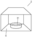
- FIG. 6 is a diagram showing a schematic configuration of the microwave oven 1 which is the microwave heating apparatus according to the second embodiment of the present invention.
- FIG. 6 is a perspective view of the microwave oven 1 as seen from the front side.
- the microwave oven 1 is configured such that the object to be heated 31 is directly placed on the placing table 6 without using the grill pan and heated in, for example, “warm mode”. Thus, it is different from the first embodiment.
- the basic configuration of the microwave oven 1 is the same as the microwave oven of the first embodiment. Therefore, the same constituent elements as those in the first embodiment are given the same reference numerals, and detailed description thereof is omitted.
- the microwave oven 1 of the present embodiment is a microwave radiated from the magnetron 3 by directly placing a large heated object 31 such as food in a container having a diameter of about 150 mm on the mounting table 6. Heating is performed in a “warming mode”.
- the object to be heated 31 is placed directly on the placing table 6. That is, the distance between the object to be heated 31 and the radiation antenna 5 arranged immediately below the mounting table 6 is reduced. Therefore, the ratio that the microwave from the radiation antenna 5 directly hits the article 31 to be heated increases. As a result, the portion of the object to be heated 31 that is positioned in the direction of strong directivity of the radiation antenna 5 is strongly heated.
- control different from the heating control in the grill mode of the first embodiment is required.
- FIG. 7 is a diagram showing the characteristics of the incident wave detection amount, the reflected wave detection amount, and the absorption amount detected by the directional coupler 30 depending on the direction of the rotating radiation antenna 5 in the microwave oven 1 shown in FIG. .
- the horizontal axis in FIG. 7 represents the direction of the radiation antenna 5, that is, the direction (rotation angle) of the tip opening portion 13. Specifically, the direction (angle) in which the front end opening portion 13 of the radiation antenna 5 faces rearward (opposite the door side) when facing the door of the microwave oven 1 is illustrated as 0 °.
- the vertical axis on the left side of FIG. 7 indicates the incident wave detection amount and the reflected wave detection amount. Specifically, it is shown that the incident wave detection amount and the reflected wave detection amount increase as it goes upward and decrease as it goes down.
- the vertical axis on the right side of FIG. 7 indicates the amount of absorption (the amount of microwave actually absorbed by the object to be heated 31) calculated from the detected amount of incident wave and the detected amount of reflected wave. Specifically, the amount of absorption decreases as it goes up and increases as it goes down, and is shown as a ratio, with the value of 90 ° in the direction of the right side radiating antenna 5 in FIG.
- heating efficiency is improved when the rotation of the radiation antenna 5 is stopped at the direction of the radiation antenna 5 of 90 °.
- baking unevenness baking unevenness
- the heating efficiency is improved, but the object to be heated 31 may not be heated uniformly.
- the inventors of the present application have a relationship between the direction (rotation angle) of the distal end opening 13 of the radiating antenna 5 and the heating part of the article 21 to be heated placed on the mounting table 6. The relationship was examined. The result is shown in FIG.
- FIG. 8 is a diagram for explaining the relationship between the direction of the radiation antenna 5 and the heated portion of the object to be heated 31.
- the object to be heated 31 is heated in the “warm mode” as described above. For this reason, it is considered that the heated object 31 has a high ratio that the microwave radiated from the radiation antenna 5 directly hits.
- the inventors of the present application have four heating portions 32a, 32b that are strongly heated with respect to four directions different from the angle of the radiation antenna 5 of 0 °, 90 °, 180 °, and 270 °. Attention was paid to the fact that 32c and 32d occur at positions in substantially the same direction.
- the amount of microwave absorption varies depending on the direction of the radiating antenna 5.
- the microwave absorption amount of the object to be heated 31 is the absorption amount 1.0 in the direction 90 ° of the radiation antenna 5> the absorption amount 0.86 in the direction 270 °> the absorption amount in the direction 180 °.
- the amount 0.63> the amount of absorption at 0 ° is 0.52. Therefore, when the same time is stopped, the heating of the object to be heated 31 in the direction (for example, 0 °) of the radiation antenna 5 having a large amount of absorption of microwaves becomes dominant.
- the rotation of the radiation antenna 5 is controlled so that the stop time becomes longer as the direction of the radiation antenna 5 having a smaller amount of absorption. That is, the control is performed so that the absorbed energy during the stop described below in the directions of the four radiation antennas 5 shown in FIG.
- each stop time was calculated so that each value of the product of the amount of absorption by the direction of the radiating antenna 5 and the stop time corresponding to the absorption energy of the microwave becomes equal.
- the stop time 5 / absorption amount.
- the stop time was calculated as 10 seconds.
- the heating strengths (sizes) of the heating portions 32a, 32b, 32c, and 32d in the directions of the radiation antennas 5 at the four locations are approximately the same.
- the heating intensities of four heating parts in the direction of the radiation antenna 5 were added. As a result, it was found that even if the object to be heated 31 was placed directly on the mounting table 6, it could be heated with a more uniform heating distribution without heating unevenness as in the grill mode.
- the microwave oven 1 is generated by the heating chamber 2a that houses the object to be heated 31, the magnetron 3 that generates the microwave to be supplied to the heating chamber 2a, and the magnetron 3.
- a waveguide 4 for transmitting the microwave to the heating chamber 2a and a radiation antenna 5 for radiating the microwave for transmitting the waveguide 4 to the heating chamber 2a are provided.
- the microwave oven 1 includes a motor 15 that rotates the radiation antenna 5, a directional coupler 30 that detects at least a part of the reflected wave in the waveguide 4, and a reflected wave detection detected by the directional coupler 30.
- a control unit 17 is provided for controlling the motor 15 and controlling the direction of the radiation antenna 5 based on the amount. And the control part 17 stops rotation of the radiation antenna 5 by the direction (for example, 90 degrees) from which reflected wave detection amount becomes the minimum, and several different directions (for example, 0 degree, 180 degrees, 270 degrees).
- the motor 15 is controlled.
- the rotation of the radiating antenna 5 is stopped in the direction in which the reflected wave detection amount is minimized.
- the heating time of the to-be-heated material 31 on the most efficient heating condition is extended. Therefore, the heating efficiency is improved as compared with the case where the radiation antenna 5 is heated at a constant speed.
- the rotation of the radiation antenna 5 is stopped in three different directions from the minimum direction. Thereby, apart from the heating unevenness that occurs during the stop in the direction in which the detected amount of the reflected wave is minimized, heating unevenness due to microwave radiation from three different directions occurs. As a result, the heating unevenness in the minimum direction is added to the heating unevenness in the three different directions and is canceled out. As a result, uniform heating with reduced heating unevenness can be obtained compared to the case where the reflected wave detection amount is stopped only in the direction in which the reflected wave detection amount is minimum. That is, both improvement in heating efficiency and uniform heating can be realized simultaneously.
- the control unit 17 has a different direction (for example, 0 °, 180 °) than the stop time of the radiation antenna 5 in the direction (for example, 90 °) in which the reflected wave detection amount is the minimum.
- the motor 15 may be controlled so as to lengthen the stop time of the radiation antenna 5 at 270 °. That is, the object to be heated 31 is heated most efficiently in the direction in which the detected amount of reflected wave is minimized. For this reason, if the orientation is minimized and stopped for the same time as other different orientations, uneven heating is more intense. On the other hand, in different directions, the heating efficiency is worse than the direction in which the amount of reflected wave detection is minimized.
- the control unit 17 lengthens the stop time of the radiation antenna 5 in different directions. Thereby, heating nonuniformity can be strengthened by microwave radiation from different directions. As a result, it is possible to cancel each other's heating unevenness with a good balance. Therefore, while maintaining more uniform heating, improvement in heating efficiency and uniform heating can be realized at the same time.
- an incident wave detection unit that detects at least a part of the incident wave in the waveguide 4 is further provided.
- the control unit 17 absorbs the microwaves by the heated object 31 from the incident wave detection amount and the reflected wave detection amount in a plurality of directions (for example, 90 °, 0 °, 180 °, 270 °) for stopping the radiation antenna 5. Calculate the amount. Then, the control unit 17 may control the motor 15 so that the calculated product of the absorption amount at each stop position and the stop time are equal (for example, set to 5 in the present embodiment).
- the product of the absorption amount and the stop time corresponds to the absorbed energy absorbed by the article 31 to be heated. Therefore, the absorption energy that generates heating unevenness in the direction (for example, 90 °) in which the reflected wave detection amount is minimum and the absorption energy that generates heating unevenness in different directions (for example, 0 °, 180 °, and 270 °) are used. Make equal. Thereby, mutual heating unevenness can be canceled with the best balance. That is, while maintaining the most uniform heating, an improvement in efficiency and a uniform heating can be realized simultaneously.
- the control unit 17 sets the direction (for example, 90 °) at which the reflected wave detection amount is minimum as the reference direction.
- the motor 15 may be controlled so as to stop the rotation of the radiation antenna 5 in a direction rotated by (360 / (N + 1)) degrees from the reference direction and the reference direction.
- N the ratio of the direction in which the reflected wave detection amount is minimum, that is, the direction in which the reflected wave is most efficiently heated, and to preferentially improve the heating efficiency.
- the configuration in which the rotation of the radiating antenna 5 is stopped for a predetermined time has been described as an example, but the present invention is not limited to this.
- the rotation speed of the radiation antenna 5 in a predetermined direction may be reduced to increase the time.
- the configuration may be such that the radiating antenna 5 is driven to rotate forward / reversely in a narrow angle range with a predetermined direction as a reference to lengthen the time.
- the stop angle of the radiating antenna 5 is just an angle such as 90 °
- the radiation antenna 5 may be stopped by 90 ° to ⁇ 10 °. This is because there is usually play (play) in the fitting state of the motor 15 and the radiation antenna 5.
- the motor 15 is a stepping motor, it can be rotated clockwise or counterclockwise. For this reason, even if the control unit 17 controls the radiating antenna 5 to stop at a predetermined angle, there is a possibility that the control unit 17 may easily shift by about 10 ° depending on the rotation direction and the size of the play.
- the directional coupler includes the reflected wave detection unit that detects at least a part of the reflected wave of the microwave propagating in the waveguide 40 and the incident wave (or traveling wave) in the waveguide 40. And an incident wave detection unit that detects at least a part of the signal.
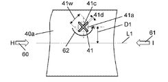
- FIG. 9 is a perspective view of the directional coupler.
- FIG. 10 is a perspective view of the directional coupler shown in FIG. 9 seen through.
- FIG. 11 is a configuration diagram of a cross opening provided in the waveguide of the directional coupler of FIG.
- FIG. 12 is a circuit configuration diagram of a printed circuit board of the directional coupler of FIG.
- the directional coupler 30 includes an X-shaped cross opening 41 provided on the wide surface 40 a of the waveguide 40, and a microstrip line 43 formed on the printed circuit board 42.
- the printed circuit board 42 faces the cross opening 41 and is provided outside the waveguide 40.
- the microstrip line 43 is configured in a predetermined line shape to be described later on a printed circuit board 42 in a region facing the cross opening region 41a (see FIG. 11).
- the cross opening area 41a is an area where the opening of the cross opening 41 exists when the cross opening 41 is viewed from the printed board 42 on the surface facing the cross opening 41 of the printed board 42.
- the support portion 44 supports and fixes the printed circuit board 42 on the outer surface of the waveguide 40 on the wide surface 40a side.
- the support portion 44 is made of a conductive material, confines microwaves radiated from the cross opening 41 of the waveguide 40 inside, and shields radiation to the outside.
- the cross opening 41 is composed of, for example, an X-shaped opening with the opening central portion 41c as a base point. As shown in FIG. 11, the cross opening 41 is provided on the wide surface 40 a of the waveguide 40 at a position that does not intersect the tube axis L ⁇ b> 1 of the waveguide 40.
- the opening center portion 41 c of the cross opening 41 is provided at a position deviated from the tube axis L 1 of the waveguide 40 by the dimension D 1.
- the dimension D1 is, for example, a dimension that is 1 ⁇ 4 of the width dimension of the waveguide 40.
- the opening shape of the cross opening 41 is based on conditions such as the width and height of the waveguide 40, the power level and frequency band of the microwave transmitted through the waveguide 40, and the power level radiated from the cross opening 41. It is determined.
- the width dimension of the waveguide 40 is 100 mm
- the height dimension is 30 mm
- the thickness of the wall surface of the waveguide 40 is 0.6 mm
- the maximum power level of the microwave transmitted through the waveguide 40 is 1000 W
- the frequency band Is 2450 MHz and the maximum power level radiated from the cross opening 41 is about 10 mW
- the length 41 w and the width 41 d of the cross opening 41 may be configured to have a length of about 20 mm and a width of about 2 mm.
- FIG. 11 illustrates an example in which the crossing angle of the X-shaped cross opening 41 is about 90 degrees, but the present invention is not limited to this.
- the intersection angle may be 60 degrees or 120 degrees.
- the opening center part 41c of the cross opening 41 is arranged on the tube axis L1 of the waveguide 40, the electric field reciprocates in the transmission direction without rotating. Therefore, linearly polarized waves are radiated from the cross opening 41.
- the opening center portion 41c is arranged so as to be shifted from the tube axis L1, the electric field rotates.
- elliptical circularly polarized waves (referred to as elliptically polarized waves) are radiated from the cross opening 41.
- the dimension D1 is set to about 1 ⁇ 4 of the width dimension of the waveguide 40.
- the rotation of the electric field becomes substantially circular (including a perfect circle). Therefore, circularly polarized waves that rotate in a substantially circular shape are radiated from the cross opening 41.
- the traveling wave and reflected wave which transmit the waveguide 40 can be isolate
- the directional coupler 30 can detect the traveling wave and the reflected wave with high accuracy.
- the printed circuit board 42 is formed with a microwave reflecting member by bonding a copper foil or the like, for example, to the entire surface of the printed circuit board A surface 42 a that does not face the cross opening 41. This prevents transmission of circularly polarized light radiated from the cross opening 41 to the printed circuit board 42.
- the printed circuit board 42 is provided with a microstrip line 43 as shown in FIG. 12 on the printed circuit board B surface 42 b facing the cross opening 41.
- the microstrip line 43 is constituted by a transmission line having a characteristic impedance of approximately 50 ohms (including 50 ohms), for example.
- the microstrip line 43 is disposed so as to surround the opening center portion 41 c of the cross opening 41 in a plan view in which the cross opening 41 side is viewed from the printed circuit board 42. Thereby, the opening center part 41 c of the cross opening 41 is included in the line of the microstrip line 43 in a bird's-eye view.
- the microstrip line 43 includes at least a first line 43a and a second line 43b disposed substantially perpendicularly (including vertical) to the tube axis L1 of the waveguide 40.
- the first line 43a and the second line 43b are opposed to the cross opening region 41a where the cross opening 41 is present in a plan view, and are disposed on both sides of the opening center portion 41c of the cross opening 41.
- first line 43a and the second line 43b is connected to a third line 43c disposed substantially parallel (including parallel) to the tube axis L1 of the waveguide 40.
- the first line 43a, the second line 43b, and the third line 43c are arranged so as to surround the opening center portion 41c of the cross opening 41.
- the other end of each of the first line 43a and the second line 43b is connected to one end of a line 43d and a line 43e disposed substantially parallel to (including parallel to) the tube axis L1, and extends to the outside of the cross opening region 41a.
- the lines extending from the other ends of the line 43d and the line 43e to the output units 131 and 132 of the microstrip line 43 are arranged via the appropriate microstrip line 43 according to the arrangement position of the output unit. At this time, the output units 131 and 132 are disposed outside the support unit 44.
- the output units 131 and 132 at both ends of the microstrip line 43 are connected to the detection circuit 45.
- the detection circuit 45 constitutes a processing circuit for handling the detected microwave level as a control signal.
- the detection circuit 45 includes a chip resistor 46, a Schottky diode 47, and the like as shown in FIG.
- the microwave signal of the output unit 131 is rectified through the detection circuit 45.
- the rectified microwave signal is converted into a DC voltage through a smoothing circuit including, for example, a chip resistor and a chip capacitor.
- the converted DC voltage is output to the detection output unit 48.
- the microwave signal of the output unit 132 is also output to the detection output unit 49 through the same circuit as described above.
- copper foil serving as a ground surface is formed in the peripheral parts of the printed circuit board mounting holes 50a, 50b, 50c, 50d and the peripheral parts of the pinfalls 51a, 51b. Is done.
- the region where the copper foil is formed has the same potential as the printed circuit board A surface 42 a that does not face the cross opening 41 of the printed circuit board 42.
- the printed circuit board 42 is assembled and fixed to the support portion 44 by screws 201a, 201b, 201c, and 201d through the printed circuit board mounting holes 50a, 50b, 50c, and 50d.
- the flange surface 44a of the support portion 44 is provided with protruding screw portions 202a, 202b, 202c, and 202d for assembling and fixing screws 201a, 201b, 201c, and 201d.
- the support portion 44 includes take-out portions 141 and 142.
- the extraction units 141 and 142 extract the microwaves transmitted through the microstrip line 43 by transmitting the microwave signals to the output units 131 and 132 arranged outside the support unit 44.
- the take-out portions 141 and 142 are formed by projecting and drawing the flange surface 44a of the support portion 44 for screw-assembling the printed circuit board 42 to the support portion 44, for example, on the opposite side of the print substrate 42. Thereby, the microwave transmitted through the microstrip line 43 is configured not to be blocked by the support portion 44.
- FIG. 9 and 10 show connector portions 48a and 49a mounted on the detection output portions 48 and 49 shown in FIG.
- the directional coupler may be configured to detect only one direction of microwaves transmitted through the waveguide 40.
- This configuration can be realized by replacing the detection circuit 45 shown in FIG. 12 with a termination circuit (not shown).
- the termination circuit may be constituted by a chip resistor having a resistance value of 50 ohms.
- the ratio of the amount of microwave power radiated from the X-shaped cross opening 41 to the amount of microwave power transmitted through the waveguide 40 is determined by the waveguide shape and the cross-opening geometry.
- the ratio of the electric energy is about 1/100000 (about ⁇ 50 dB).
- an arrow H shown in FIGS. 9 to 12 indicates an incident wave (or traveling wave, hereinafter referred to as traveling wave 60) of the transmitted microwave.
- An arrow I indicates a reflected wave (hereinafter referred to as a reflected wave 61).
- the traveling wave 60 is sequentially excited by the two openings in the length 41 w direction forming the cross opening 41 when transmitting through the waveguide 40. Then, the microwave radiated from the cross opening 41 becomes a circularly polarized wave 62 that rotates counterclockwise (see FIG. 11) and is radiated to the outside of the waveguide 40.
- the reflected wave 61 is circularly polarized light that radiates in a clockwise direction and is radiated to the outside of the waveguide 40.
- the circularly polarized microwave radiated by rotation is coupled to the microstrip line 43 facing the cross opening 41.
- the microwave radiated from the cross opening 41 by the traveling wave 60 transmitted in the direction of the arrow H is output to the output units 131 and 132 of the microstrip line 43.
- most of the microwave generated by the traveling wave 60 needs to be output to the output unit 131.
- the microwave radiated from the cross opening 41 by the reflected wave 61 transmitted in the direction of the arrow I is output to the output units 131 and 132 of the microstrip line 43.
- most of the microwave generated by the reflected wave 61 needs to be output to the output unit 132.
- the structure of the microstrip line 43 facing the cross opening 41 is important in order to output to a predetermined output unit in the microwave transmission direction.
- the inventors of the present application intensively studied the relative position of the microstrip line 43 facing the cross opening 41. As a result, it has been found that the microstrip line 43 can be realized so as to surround the opening central portion 41c of the cross opening 41 when the cross opening 41 side is viewed from the printed circuit board 42.
- the microstrip line 43 surrounding the opening center portion 41c is used.
- the microstrip line 43 includes a first line 43a, a second line 43b, a first line 43a, and a second line 43b that are substantially perpendicular (including vertical) to the tube axis L1 of the waveguide 40.
- the third line 43c is substantially parallel (including parallel) to the tube axis L1 of the waveguide 40 to which one end of the waveguide 40 is connected.
- the first line 43 a and the second line 43 b have lengths facing (crossing) each of the two openings in the length 41 w direction forming the cross opening 41.
- the third line 43c is configured not to face the opening of the cross opening 41.
- microstrip line 43 Due to the configuration of the microstrip line 43, most of the microwave radiated from the cross opening 41 by the traveling wave 60 was output to the output unit 131 of the microstrip line 43. On the other hand, most of the microwave radiated from the cross opening 41 by the reflected wave 61 was output to the output unit 132 of the microstrip line 43.
- the microwave 40 and the reflected wave 61 are transmitted in opposite directions using the waveguide 40, it is necessary to apply the above-described method for outputting a large part to a predetermined output unit. is there. Therefore, it is necessary to provide symmetry to the arrangement of the microstrip line 43 that surrounds the opening center portion 41 c of the cross opening 41. Therefore, in the present embodiment, the first line 43a and the second line 43b of the microstrip line 43 are arranged at substantially equal distances (including equal distances) from the opening center part 41c.
- the detection separation degree of the traveling wave 60 and the reflected wave 61 detected by the directional coupler can be improved.
- the traveling wave 60 and the reflected wave 61 are transmitted in opposite directions in the waveguide 40, a standing wave is generated in the waveguide 40.
- the standing wave may reduce the detection separation between the traveling wave 60 and the reflected wave 61.
- the inventors of the present application examined the distance 43g between the first line 43a and the second line 43b of the microstrip line 43 in order to suppress the influence of the standing wave. The result will be described with reference to FIGS.
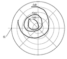
- FIG. 13 is a polar coordinate diagram showing the output characteristics of the reflected wave detector in the directional coupler 30 when the distance 43g between the first line 43a and the second line 43b is 4 mm.
- FIG. 14 is a polar coordinate diagram showing the output characteristics of the reflected wave detector in the directional coupler 30 when the distance 43g between the first line 43a and the second line 43b is 2 mm.
- FIG. 15 is a polar coordinate diagram showing output characteristics of the traveling wave detector of the directional coupler 30 under the conditions of FIG.
- the characteristics are set. evaluated.
- a microwave input end is connected to one end of the waveguide 40 configured as described above, and a load capable of changing the level and phase of the reflected wave 61 is connected to the other end of the waveguide 40. Then, a microwave signal is input from the microwave input end of the waveguide 40.
- the level and phase of the reflected wave 61 are changed, and the output units 131 (traveling wave detection) and 132 (reflected wave detection) of the microstrip line 43 are changed. ) Is measured using a network analyzer. At this time, the amount of power of the microwave (traveling wave) detected by the output unit 131 is S21. On the other hand, the electric energy of the microwave (reflected wave) detected by the output unit 132 is S31.
- the reference plane 80 shown in FIG. 13 and FIG. 14 is a plane which shows the input end of the load as a reference, and all the traveling waves 60 are completely reflected and the phase changes by 180 degrees.
- the center of the polar coordinate display indicates that the electric energy S31 of the reflected wave 61 is zero.
- the circumference which is the outermost contour of the polar coordinate display, indicates that all the traveling waves 60 become reflected waves 61. That is, the closer to the outermost circumference from the center of polar coordinate display, the greater the amount of power S31 of the reflected wave 61. Therefore, a value (S31 ⁇ S21) obtained by subtracting the power amount S21 of the traveling wave 60 from the power amount S31 of the reflected wave 61 is small. Since FIG. 13 and FIG. 14 are expressed in dB, the negative value becomes small.
- the circumferential direction of the polar coordinate display indicates the phase of the reflected wave 61 at the position where the directional coupler 30 is disposed in relation to the phase.
- the phase is displayed in a relative manner. That is, on the same circumference in polar coordinate display, the phase of the reflected wave 61 is different, but the electric energy (power level) of the reflected wave 61 is the same. Therefore, when the value (S31-S21) obtained by subtracting the power amount S21 of the traveling wave 60 from the power amount S31 of the reflected wave 61 is developed on the polar coordinates, the ideal characteristic is that the contour lines are concentric.
- FIGS. 13 and 14 were analyzed.
- the propagation direction of the microwave radiated from the cross opening 41 is approximately 50 degrees upward from the cross opening 41 with respect to the transmission direction in the waveguide 40. Therefore, it is presumed that the occurrence of standing waves can be suppressed by arranging the first line 43a and the second line 43b at a position where the first line 43a and the second line 43b rotate and emit at about 50 degrees.
- the inventors of the present application arranged the first line 43 a and the second line 43 b so as to face the opening of the cross opening 41. At this time, the suppression of the standing wave was examined by selecting an appropriate dimension of, for example, 5 to 7 mm as the distance between the wide surface 40a of the waveguide 40 and the printed circuit board B surface 42b on which the microstrip line 43 is disposed. . Thereby, it was confirmed that the generation of standing waves can be suppressed.
- FIG. 15 is a polar coordinate diagram showing the output characteristics of the traveling wave detector in the directional coupler of FIG. That is, FIG. 15 is a diagram in which the electric energy S21 of the microwave (corresponding to the traveling wave) detected by the output unit 131 of the directional coupler 30 is displayed in polar coordinates.
- the variation in the detected amount of the traveling wave in consideration of the load fluctuation is about ⁇ 50.5 dB to ⁇ 53.0 dB with respect to the entire polar coordinate region.
- the detection circuit 45 the smaller the variation, the easier the signal processing by the detection circuit 45. For this reason, it is possible to use inexpensive parts for the Schottky diode 47 constituting the detection circuit 45 within the above-described range of variation. Further, even if the detection circuit 45 is configured with inexpensive parts, signal processing can be easily performed.
- the region surrounded by the first line 43a, the second line 43b, and the third line 43c is not particularly mentioned, but is preferably smaller than the cross opening region 41a.
- the first line 43a and the second line 43b are arranged in the middle of the opening center portion 41c and the end portions of the cross opening region 41a (left and right end portions in FIG. 12).
- the third line 43c is arranged in the middle of the opening center portion 41c and the end portion of the cross opening region 41a (the upper end portion indicated by a one-dot chain line in FIG. 12).
- the X shape in which two long holes intersect is described as an example of the opening shape of the cross opening 41, but the shape is not limited thereto.
- the opening shape of the cross opening 41 may be a shape that includes two or more long holes inclined at different angles with respect to the tube axis L1 of the waveguide 40, for example.
- the crossing position of two or more long holes may be shifted from the center of the long hole.
- the opening shape of the cross opening 41 may be, for example, an L shape or a T shape.
- the electric field can be rotated to radiate circularly polarized waves.
- the X-shaped two long holes are arranged so as to be orthogonal to each other at the center, since a substantially circular circularly polarized wave can be emitted.
- the opening shape of the cross opening 41 may be a circle or a polygon. That is, as described above, the opening shape may be any shape that includes two or more long holes inclined at different angles with respect to the tube axis L1 of the waveguide 40. Therefore, it may be a circle formed by overlapping a number of long holes by changing the angle little by little, or a square connecting the four vertices of an X-shaped long hole. Furthermore, an ellipse, a rectangle, or a trapezoid obtained by crushing a shape such as a circle or a square may be used. Further, it may be a polygon other than a quadrangle or a complicated shape such as a heart shape or a star shape. In particular, in the case of a circle or a quadrangle, an effect that is less likely to be deformed can be obtained as compared to a complicated shape such as an X shape.
- the microwave heating apparatus of the present invention generates a heating chamber that houses an object to be heated, a microwave generation unit that generates a microwave to be supplied to the heating chamber, and a microwave generation unit.
- a waveguide that transmits microwaves to the heating chamber, a radiation antenna that radiates microwaves that transmit the waveguide to the heating chamber, and a rotation drive unit that rotates the radiation antenna are provided.
- the microwave heating device controls the drive of the rotation drive unit based on the reflected wave detection unit that detects at least a part of the reflected wave in the waveguide and the reflected wave detection amount detected by the reflected wave detection unit.
- a control unit for controlling the direction of the radiation antenna is provided.
- the control unit has a configuration for controlling the rotation driving unit so as to stop the rotation of the radiation antenna in a direction in which the reflected wave detection amount is minimum and in a direction different from the minimum direction.
- the rotation of the radiation antenna is stopped in the direction in which the reflected wave detection amount is minimized.
- the heating time which heats a to-be-heated material on the most efficient heating conditions is extended. Therefore, the heating efficiency is further improved as compared with the case where the radiation antenna is heated while being rotated at a constant rotation.
- the rotation of the radiation antenna is stopped in a direction different from the minimum direction. At this time, in addition to the heating unevenness that occurs during the stop in the direction in which the detected amount of the reflected wave is minimized, the heating unevenness due to the microwave radiation from different directions occurs.
- control unit of the microwave heating apparatus of the present invention may control the rotation driving unit so as to change the stop time depending on the direction of the radiation antenna.
- distribution of the heating nonuniformity which arises while the direction of each radiation antenna stops can be changed.
- control unit of the microwave heating device of the present invention may control the rotation drive unit so that the stop time in a different direction is longer than the stop time in the direction in which the reflected wave detection amount is minimized.
- the object to be heated is heated most efficiently in the direction where the reflected wave detection amount is minimized. For this reason, if the direction is minimized and stopped for the same time as the different direction, uneven heating is more intense.
- the heating efficiency is worse than the direction in which the amount of reflected wave detection is minimized. Therefore, slightly weaker heating unevenness occurs in the object to be heated when microwaves are emitted from different directions. Therefore, the stop time of the radiating antenna is lengthened in different directions. Thereby, heating unevenness can be strengthened by microwave radiation from different directions. Therefore, it is possible to cancel each other's heating unevenness with a good balance. As a result, while achieving further uniform heating, improvement in heating efficiency and uniform heating can be realized simultaneously.
- the microwave heating device of the present invention further includes an incident wave detection unit that detects at least a part of the incident wave in the waveguide.
- the control unit calculates the amount of microwave absorption by the object to be heated from the amount of incident wave detection and the amount of reflected wave detection in a plurality of different directions for stopping the radiation antenna.
- a control part may control a rotation drive part so that the product of the absorption amount and stop time in each stop position calculated may become equal.
- the product of the absorption amount and the stop time corresponds to the absorbed energy absorbed by the heated object. Therefore, the absorbed energy that generates the heating unevenness in the direction in which the detected amount of the reflected wave is minimized is made equal to the absorbed energy that generates the heating unevenness in a plurality of different directions. Thereby, mutual heating unevenness can be canceled with the best balance. That is, while realizing the most uniform heating, it is possible to simultaneously improve heating efficiency and uniform heating.
- the control unit sets the reference direction and the reference direction as the reference direction with the direction in which the reflected wave detection amount is minimized.
- the rotation driving unit may be controlled so as to stop the rotation of the radiation antenna in a direction rotated by (360 ° / (N + 1)) degrees from the angle.
- N the ratio of the direction in which the reflected wave detection amount is minimum, that is, the direction in which the reflected wave is most efficiently heated, and to preferentially improve the heating efficiency.
- the control unit stops in the direction in which the reflected wave detection amount is minimum and the different direction rotated by 180 °.
- the rotational drive unit may be controlled.
- the microwave heating apparatus of the present invention is useful for a heating cooker that radiates microwaves to food as an object to be heated and dielectrically heats it, particularly a heating cooker that is used in combination with other heating such as an oven, a grill, and superheated steam. is there. Furthermore, the microwave heating apparatus is useful in various industrial applications such as a drying apparatus, a ceramic heating apparatus, a garbage disposal machine, a semiconductor manufacturing apparatus, and a chemical reaction apparatus.
- Microwave oven microwave heating device 2 Heating chamber space 2a Heating chamber 2b Power feeding chamber 2bb, 14a, 14b Opening 2c, 2d Side wall 3 Magnetron (microwave generator) 3a output end 4,40 waveguide 5 radiating antenna (waveguide structure antenna) 6 Mounting Table 7 Coupling Unit 7a Coupling Shaft 7b Flange 8 Waveguide Structure Unit 11 Bottom Wall 13 Tip Opening Unit 15 Motor (Rotation Drive Unit) 16 Infrared sensor 17 Control part 18a, 18b Protrusion part 20 Grill pan 20a Peripheral part 20ad Corner part 20b Groove 20c Plate 20d Insulation part 20e Microwave absorption heating element 20f Bottom face 21, 31 Heated object 22a, 22b, 22c, 22d Corner part 30 Directional coupler (reflected wave detector) 32a, 32b, 32c, 32d Heating part 40a Wide surface 41 Cross opening 41a Cross opening region 41c Center of opening 41d Width 41w Length 42 Printed circuit board 42a Printed circuit board A surface 42b Printed circuit board B
Landscapes
- Physics & Mathematics (AREA)
- Electromagnetism (AREA)
- Engineering & Computer Science (AREA)
- Chemical & Material Sciences (AREA)
- Combustion & Propulsion (AREA)
- Mechanical Engineering (AREA)
- General Engineering & Computer Science (AREA)
- Constitution Of High-Frequency Heating (AREA)
- Control Of High-Frequency Heating Circuits (AREA)
Abstract
Description
図1は、本発明の実施の形態1におけるマイクロ波加熱装置の一例である電子レンジの概略構成を示す断面図である。具体的には、図1は、電子レンジ1を正面側から見た断面図である。
以下に、本発明の実施の形態2におけるマイクロ波加熱装置について、図6を用いて、説明する。
以下に、上記各実施の形態に関わる方向性結合器の構成および動作について、図9から図12を用いて、詳細に説明する。
2 加熱室空間
2a 加熱室
2b 給電室
2bb,14a,14b 開口
2c,2d 側壁
3 マグネトロン(マイクロ波発生部)
3a 出力端
4,40 導波管
5 放射アンテナ(導波管構造アンテナ)
6 載置台
7 結合部
7a 結合軸
7b フランジ
8 導波構造部
11 底壁
13 先端開放部
15 モータ(回転駆動部)
16 赤外線センサ
17 制御部
18a,18b 突出部
20 グリル皿
20a 周囲部
20ad コーナー部
20b 溝
20c プレート
20d 絶縁部
20e マイクロ波吸収発熱体
20f 底面
21,31 被加熱物
22a,22b,22c,22d 隅部
30 方向性結合器(反射波検出部)
32a,32b,32c,32d 加熱部位
40a 幅広面
41 クロス開口
41a クロス開口領域
41c 開口中央部
41d 幅
41w 長さ
42 プリント基板
42a プリント基板A面
42b プリント基板B面
43 マイクロストリップ線路
43a 第1線路
43b 第2線路
43c 第3線路
43d,43e 線路
43g 間隔
44 支持部
44a フランジ面
45 検波回路
46 チップ抵抗
47 ショットキーダイオード
48,49 検波出力部
48a,49a コネクタ部
50a,50b,50c,50d プリント基板取付用穴
51a,51b ピンフォール
60 入射波(進行波)
61 反射波
62 回転放射
80 基準面
131,132 出力部
141,142 取出し部
201a,201b,201c,201d ネジ
202a,202b,202c,202d 突出しネジ部
D1 寸法
E,F,H,I 矢印
G 回転中心
J 中心線
L1 管軸
Claims (6)
- 被加熱物を収納する加熱室と、
前記加熱室に供給するマイクロ波を発生させるマイクロ波発生部と、
前記マイクロ波発生部で発生させた前記マイクロ波を前記加熱室に伝送する導波管と、
前記導波管を伝送する前記マイクロ波を前記加熱室に放射させる放射アンテナと、
前記放射アンテナを回転させる回転駆動部と、
前記導波管内の反射波の少なくとも一部を検出する反射波検出部と、
前記反射波検出部が検出した反射波検出量に基づいて、前記回転駆動部の駆動を制御し前記放射アンテナの向きを制御する制御部と、を備え、
前記制御部は、前記反射波検出量が最小となる向き、および前記最小となる向きと異なる向きで、前記放射アンテナを停止させるように前記回転駆動部を制御するマイクロ波加熱装置。 - 前記制御部は、前記放射アンテナの前記向きによって停止時間を変えるように前記回転駆動部を制御する請求項1記載のマイクロ波加熱装置。
- 前記制御部は、前記反射波検出量が最小となる向きにおける前記放射アンテナの停止時間よりも、前記異なる向きにおける停止時間を長くするように前記回転駆動部を制御する請求項2記載のマイクロ波加熱装置。
- 前記導波管内の入射波の少なくとも一部の入射波検出量を検出する入射波検出部を、さらに有し、
前記制御部は、前記放射アンテナを停止させる複数の前記異なる向きにおける前記入射波検出量と前記反射波検出量から前記被加熱物による前記マイクロ波の吸収量を算出し、それぞれの停止位置での前記吸収量と停止時間の積を等しくなるように前記回転駆動部を制御する請求項1記載のマイクロ波加熱装置。 - 前記放射アンテナを停止させる前記異なる向きがN箇所の場合、
前記制御部は、前記反射波検出量が最小となる向きを基準の向きとして、前記基準の向きおよび前記基準の向きから(360°/(N+1))度ずつ回転した向きで前記放射アンテナを停止するように前記回転駆動部を制御する請求項1記載のマイクロ波加熱装置。 - 前記放射アンテナを停止させる前記異なる向きが1箇所の場合、
前記制御部は、前記反射波検出量が最小となる向きと、180°回転した前記異なる向きで停止するように前記回転駆動部を制御する請求項5記載のマイクロ波加熱装置。
Priority Applications (4)
| Application Number | Priority Date | Filing Date | Title |
|---|---|---|---|
| EP17770330.3A EP3435737B1 (en) | 2016-03-25 | 2017-03-23 | Microwave heating device |
| JP2018507400A JP6887077B2 (ja) | 2016-03-25 | 2017-03-23 | マイクロ波加熱装置 |
| US16/081,038 US10912165B2 (en) | 2016-03-25 | 2017-03-23 | Microwave heating device |
| CN201780016969.XA CN108781486B (zh) | 2016-03-25 | 2017-03-23 | 微波加热装置 |
Applications Claiming Priority (2)
| Application Number | Priority Date | Filing Date | Title |
|---|---|---|---|
| JP2016-061033 | 2016-03-25 | ||
| JP2016061033 | 2016-03-25 |
Publications (1)
| Publication Number | Publication Date |
|---|---|
| WO2017164290A1 true WO2017164290A1 (ja) | 2017-09-28 |
Family
ID=59900359
Family Applications (1)
| Application Number | Title | Priority Date | Filing Date |
|---|---|---|---|
| PCT/JP2017/011664 Ceased WO2017164290A1 (ja) | 2016-03-25 | 2017-03-23 | マイクロ波加熱装置 |
Country Status (5)
| Country | Link |
|---|---|
| US (1) | US10912165B2 (ja) |
| EP (1) | EP3435737B1 (ja) |
| JP (1) | JP6887077B2 (ja) |
| CN (1) | CN108781486B (ja) |
| WO (1) | WO2017164290A1 (ja) |
Cited By (1)
| Publication number | Priority date | Publication date | Assignee | Title |
|---|---|---|---|---|
| CN108770107A (zh) * | 2018-08-02 | 2018-11-06 | 电子科技大学 | 一种用于柱状物体加热的微波装置 |
Families Citing this family (5)
| Publication number | Priority date | Publication date | Assignee | Title |
|---|---|---|---|---|
| CN113474942B (zh) * | 2019-02-22 | 2022-07-15 | 松下知识产权经营株式会社 | 微波加热装置 |
| CN110279151A (zh) * | 2019-06-19 | 2019-09-27 | 云南巴菰生物科技有限公司 | 一种微波加热不燃烧烟具 |
| CN113494723B (zh) * | 2020-03-20 | 2025-06-20 | 青岛海尔智能技术研发有限公司 | 一种加热装置及用于加热装置的控制方法 |
| CN112697953B (zh) * | 2020-11-27 | 2022-02-08 | 中国矿业大学 | 一种多可变参数环境条件下电缆燃烧及热解特性测试系统及测试方法 |
| CN114665242B (zh) * | 2022-04-06 | 2023-03-24 | 湖南大学 | 利用可调人工磁导体改善微波腔内电磁场均匀性的装置及方法 |
Citations (2)
| Publication number | Priority date | Publication date | Assignee | Title |
|---|---|---|---|---|
| JPH0778681A (ja) * | 1993-09-07 | 1995-03-20 | Hitachi Home Tec Ltd | 高周波加熱装置 |
| JP2003234174A (ja) * | 2002-02-07 | 2003-08-22 | Hitachi Hometec Ltd | 高周波加熱装置 |
Family Cites Families (14)
| Publication number | Priority date | Publication date | Assignee | Title |
|---|---|---|---|---|
| EP0788296B1 (en) * | 1994-04-07 | 2005-03-23 | Matsushita Electric Industrial Co., Ltd. | High-frequency heating device |
| EP1220572A3 (en) * | 1994-10-20 | 2007-07-18 | Matsushita Electric Industrial Co., Ltd. | High frequency heating apparatus |
| JP3600094B2 (ja) * | 1999-12-07 | 2004-12-08 | 三洋電機株式会社 | 電子レンジ |
| AU2003255163A1 (en) * | 2002-08-02 | 2004-02-23 | Sharp Kabushiki Kaisha | High-frequency heating apparatus |
| JP2005315487A (ja) * | 2004-04-28 | 2005-11-10 | Matsushita Electric Ind Co Ltd | マイクロ波加熱方法及びその装置 |
| JP4979280B2 (ja) * | 2006-06-19 | 2012-07-18 | パナソニック株式会社 | マイクロ波加熱装置 |
| JP5076626B2 (ja) * | 2007-05-11 | 2012-11-21 | パナソニック株式会社 | マイクロ波加熱装置 |
| JP5034667B2 (ja) * | 2007-05-14 | 2012-09-26 | パナソニック株式会社 | マイクロ波加熱装置 |
| JP5124200B2 (ja) * | 2007-08-02 | 2013-01-23 | 日立アプライアンス株式会社 | 高周波加熱装置 |
| JP5152971B2 (ja) * | 2007-12-27 | 2013-02-27 | パナソニック株式会社 | 加熱調理器 |
| JP2011060530A (ja) * | 2009-09-09 | 2011-03-24 | Panasonic Corp | マイクロ波処理装置 |
| JP2011086486A (ja) * | 2009-10-15 | 2011-04-28 | Panasonic Corp | マイクロ波加熱装置 |
| JP5624137B2 (ja) * | 2010-07-09 | 2014-11-12 | シャープ株式会社 | 電子レンジ |
| US10135107B2 (en) | 2013-01-31 | 2018-11-20 | Panasonic Intellectual Property Management Co., Ltd. | Directional coupler and microwave heater provided with the same |
-
2017
- 2017-03-23 WO PCT/JP2017/011664 patent/WO2017164290A1/ja not_active Ceased
- 2017-03-23 CN CN201780016969.XA patent/CN108781486B/zh active Active
- 2017-03-23 US US16/081,038 patent/US10912165B2/en active Active
- 2017-03-23 EP EP17770330.3A patent/EP3435737B1/en active Active
- 2017-03-23 JP JP2018507400A patent/JP6887077B2/ja active Active
Patent Citations (2)
| Publication number | Priority date | Publication date | Assignee | Title |
|---|---|---|---|---|
| JPH0778681A (ja) * | 1993-09-07 | 1995-03-20 | Hitachi Home Tec Ltd | 高周波加熱装置 |
| JP2003234174A (ja) * | 2002-02-07 | 2003-08-22 | Hitachi Hometec Ltd | 高周波加熱装置 |
Cited By (2)
| Publication number | Priority date | Publication date | Assignee | Title |
|---|---|---|---|---|
| CN108770107A (zh) * | 2018-08-02 | 2018-11-06 | 电子科技大学 | 一种用于柱状物体加热的微波装置 |
| CN108770107B (zh) * | 2018-08-02 | 2024-04-19 | 电子科技大学 | 一种用于柱状物体加热的微波装置 |
Also Published As
| Publication number | Publication date |
|---|---|
| JP6887077B2 (ja) | 2021-06-16 |
| CN108781486B (zh) | 2021-08-10 |
| JPWO2017164290A1 (ja) | 2019-01-31 |
| EP3435737A1 (en) | 2019-01-30 |
| CN108781486A (zh) | 2018-11-09 |
| EP3435737B1 (en) | 2021-04-28 |
| EP3435737A4 (en) | 2019-04-10 |
| US10912165B2 (en) | 2021-02-02 |
| US20190090318A1 (en) | 2019-03-21 |
Similar Documents
| Publication | Publication Date | Title |
|---|---|---|
| WO2017164290A1 (ja) | マイクロ波加熱装置 | |
| JP6906143B2 (ja) | マイクロ波加熱装置 | |
| WO2014171152A1 (ja) | マイクロ波加熱装置 | |
| WO2016006249A1 (ja) | マイクロ波加熱装置 | |
| JP6459123B2 (ja) | マイクロ波加熱装置 | |
| JP6671005B2 (ja) | マイクロ波加熱装置 | |
| JP6414683B2 (ja) | マイクロ波加熱装置 | |
| JP6331024B2 (ja) | マイクロ波加熱装置 | |
| JP6304552B2 (ja) | マイクロ波加熱装置 | |
| US20200187314A1 (en) | Multi-feed microwave oven with improved crisp function | |
| JP5169015B2 (ja) | マイクロ波加熱装置 | |
| JP6569991B2 (ja) | マイクロ波加熱装置 | |
| JP6715525B2 (ja) | マイクロ波加熱装置 | |
| JP6414684B2 (ja) | マイクロ波加熱装置 | |
| JP2007141538A (ja) | マイクロ波加熱装置 |
Legal Events
| Date | Code | Title | Description |
|---|---|---|---|
| WWE | Wipo information: entry into national phase |
Ref document number: 2018507400 Country of ref document: JP |
|
| NENP | Non-entry into the national phase |
Ref country code: DE |
|
| WWE | Wipo information: entry into national phase |
Ref document number: 2017770330 Country of ref document: EP |
|
| ENP | Entry into the national phase |
Ref document number: 2017770330 Country of ref document: EP Effective date: 20181025 |
|
| 121 | Ep: the epo has been informed by wipo that ep was designated in this application |
Ref document number: 17770330 Country of ref document: EP Kind code of ref document: A1 |