WO2017164359A1 - 縫合装置 - Google Patents
縫合装置 Download PDFInfo
- Publication number
- WO2017164359A1 WO2017164359A1 PCT/JP2017/011974 JP2017011974W WO2017164359A1 WO 2017164359 A1 WO2017164359 A1 WO 2017164359A1 JP 2017011974 W JP2017011974 W JP 2017011974W WO 2017164359 A1 WO2017164359 A1 WO 2017164359A1
- Authority
- WO
- WIPO (PCT)
- Prior art keywords
- arm
- pair
- needle
- members
- rear arm
- Prior art date
- Legal status (The legal status is an assumption and is not a legal conclusion. Google has not performed a legal analysis and makes no representation as to the accuracy of the status listed.)
- Ceased
Links
Images




Classifications
-
- A—HUMAN NECESSITIES
- A61—MEDICAL OR VETERINARY SCIENCE; HYGIENE
- A61B—DIAGNOSIS; SURGERY; IDENTIFICATION
- A61B17/00—Surgical instruments, devices or methods
- A61B17/04—Surgical instruments, devices or methods for suturing wounds; Holders or packages for needles or suture materials
- A61B17/0469—Suturing instruments for use in minimally invasive surgery, e.g. endoscopic surgery
-
- A—HUMAN NECESSITIES
- A61—MEDICAL OR VETERINARY SCIENCE; HYGIENE
- A61B—DIAGNOSIS; SURGERY; IDENTIFICATION
- A61B17/00—Surgical instruments, devices or methods
- A61B17/04—Surgical instruments, devices or methods for suturing wounds; Holders or packages for needles or suture materials
- A61B17/06—Needles ; Sutures; Needle-suture combinations; Holders or packages for needles or suture materials
- A61B17/062—Needle manipulators
-
- A—HUMAN NECESSITIES
- A61—MEDICAL OR VETERINARY SCIENCE; HYGIENE
- A61B—DIAGNOSIS; SURGERY; IDENTIFICATION
- A61B17/00—Surgical instruments, devices or methods
- A61B17/00234—Surgical instruments, devices or methods for minimally invasive surgery
- A61B2017/00292—Surgical instruments, devices or methods for minimally invasive surgery mounted on or guided by flexible, e.g. catheter-like, means
- A61B2017/00296—Surgical instruments, devices or methods for minimally invasive surgery mounted on or guided by flexible, e.g. catheter-like, means mounted on an endoscope
-
- A—HUMAN NECESSITIES
- A61—MEDICAL OR VETERINARY SCIENCE; HYGIENE
- A61B—DIAGNOSIS; SURGERY; IDENTIFICATION
- A61B17/00—Surgical instruments, devices or methods
- A61B2017/00743—Type of operation; Specification of treatment sites
- A61B2017/00818—Treatment of the gastro-intestinal system
-
- A—HUMAN NECESSITIES
- A61—MEDICAL OR VETERINARY SCIENCE; HYGIENE
- A61B—DIAGNOSIS; SURGERY; IDENTIFICATION
- A61B17/00—Surgical instruments, devices or methods
- A61B17/04—Surgical instruments, devices or methods for suturing wounds; Holders or packages for needles or suture materials
- A61B17/0469—Suturing instruments for use in minimally invasive surgery, e.g. endoscopic surgery
- A61B2017/0472—Multiple-needled, e.g. double-needled, instruments
Definitions
- the present invention relates to a suturing device. More specifically, the present invention relates to a suturing device that is attached to an endoscope and used for suturing tissue in the digestive tract.
- a laparoscope operation has been performed as a minimally invasive operation that can reduce the burden on the patient and reduce the damage formed on the body surface compared to the surgical operation.
- an operation using a flexible endoscope is performed as a less invasive operation than an operation using a laparoscope.
- the cancer can be excised by peeling the lumen from the digestive tract to the submucosal layer including the mucosal layer with a flexible endoscope.
- the operation can be performed without leaving any wound on the body surface, the burden on the patient is small, and the recovery after the operation is accelerated.
- the suturing device of this Patent Document 1 If the suturing device of this Patent Document 1 is used, the end face of the opening formed when the tumor is excised can be brought into contact with each other, so that a suturing equivalent to a surgical suturing can be realized. Moreover, if the suturing device of patent document 1 is used, not only the opening which excised the tumor but also various holes formed in the digestive tract can be sutured and closed.
- tissue when a tissue is excised from the stomach wall or the like, the tissue may come into the abdominal cavity from an opening formed in the excised site. If the excised tissue is cancer, if the cancer tissue leaks into the abdominal cavity, the cancer may metastasize to other organs. If tissue such as cancer can be excised without forming an opening in the stomach wall, etc., tissue can be excised from the digestive tract cavity more safely with a flexible endoscope. Development is desired.
- an object of the present invention is to provide a suturing device that can more easily perform tissue suturing from the digestive tract.
- a suturing device includes a front arm, a rear arm provided so as to be able to approach and separate from the front arm, and an arm moving means for approaching and separating the front arm and the rear arm.
- the front arm and the rear arm have base ends connected to the arm moving means, and the rear arm has a distal end directed toward the front arm and a central axis thereof that is the same as that of the rear arm.
- a suture needle portion having a pair of needle-like members provided so as to be parallel to a direction in which the front arm approaches and separates, and the front arm is located when the front arm and the rear arm approach each other
- a pair of storage spaces capable of storing the tip portions of the pair of needle-like members, respectively, and the pair of storage spaces of the storage portions are connected to each other by sutures.
- the needle shape Wherein the wood engageable with a pair of engaging members are housed.
- a suturing device according to a second invention is the suturing device according to the first invention, wherein the rear arm and the front side from the position where the front arm and the rear arm are connected to the arm moving means to the pair of needle-like members.
- the suturing needle portion is provided so that the pair of needle-like members are arranged in the axial direction of the rear arm,
- the pair of receiving spaces are provided so as to be aligned in the axial direction of the front arm.
- the rear arm is provided with a plurality of the suture needle portions arranged in the axial direction of the rear arm
- the front arm is provided with a plurality of storage portions corresponding to the suture needle portions so as to be aligned in the axial direction of the front arm.
- a suturing device is the first, second, third or fourth aspect of the invention, wherein the rear arm and the front arm can be moved toward and away from each other and fixed in a plane perpendicular to the direction of approaching and separating. It has the connection mechanism which connects in the state which carried out.
- the tip portions of the pair of needle-like members can be simultaneously inserted into the pair of accommodating spaces, respectively.
- the pair of engaging members connected by the suture can be simultaneously engaged with the distal ends of the pair of needle-like members.
- both ends of the suture thread are located on the rear arm side by simply sandwiching and separating the tissue such as the stomach wall once between the front arm and the rear arm.
- the suture can be passed through the tissue so that In this state, if the both ends of the suture thread are ligated, the tissue can be sutured in the same manner as in a normal surgical operation.
- a tissue having a width or length can be sutured.
- a suturing operation can be performed quickly.
- the tip portions of the pair of needle-like members can be reliably accommodated in the pair of accommodation spaces.
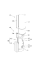
- FIG. 1 is a schematic perspective view of a suturing device 10 of the present embodiment in a state attached to a shaft 2 of an endoscope 1.
- FIG. It is the perspective view which looked at the suturing device 10 of this embodiment in the state attached to the shaft 2 of the endoscope 1 from diagonally downward.
- (A) is a cross-sectional view taken along the line VIA-VIA in FIG.
- (B) is a cross-sectional view taken along the line VIB-VIB in FIG. It is a schematic explanatory drawing of the accommodating part 17 in the front arm 11 of this embodiment. It is a schematic explanatory drawing of the suturing operation
- the suturing device of the present invention is a device that is attached to a flexible endoscope and performs suturing from the digestive tract cavity, and is characterized in that suturing can be performed easily and quickly.
- the suturing device of the present invention can be used not only for flexible endoscopes but also for attaching to the tip of a laparoscope.
- full-layer stitching of tissue is performed in the digestive tract cavity even when no opening or through-hole is formed in the digestive tract. it can.
- the full-layer suture means that a suture is sutured so as to penetrate all layers of the digestive tract (serosa, serosa lower layer, intrinsic muscle layer, submucosa, mucous membrane).
- symbol 2 has shown the shaft of the endoscope 1 to which the suturing device 10 of this embodiment is attached.
- the endoscope 1 to which the suturing device 10 of this embodiment is attached is a flexible endoscope used for general endoscopic surgery.
- the diameter, length, material, and the like are not particularly limited.
- the diameter of the shaft 2 is about 10 mm in a general endoscope, but may be about 5 to 15 mm.
- the length of the shaft 2 is about 1200 mm in a general endoscope, but may be about 1200 to 3000 mm.
- the suturing device 10 of the present embodiment (hereinafter sometimes simply referred to as the suturing device 10) includes a pair of front and rear arms 11 and 12 and an arm movement that operates the pair of front and rear arms 11 and 12. Means 13 and a coupling mechanism 40 for guiding the movement of the pair of front and rear arms 11 and 12 are provided.
- the suturing device 10 is used by being fixed to the endoscope 1 by fixing the arm moving means 13 to the shaft 2 of the endoscope 1. Specifically, the suturing device 10 is attached so that the axial direction of the arm moving means 13 is substantially parallel to the axial direction of the shaft 2.
- the arm moving means 13 can be made to follow the bending of the shaft 2 reliably when the shaft 2 is bent. Can be prevented from interfering with bending.
- the arm moving means 13 is configured such that both the pair of front and rear arms 11 and 12 are positioned in front of the front end surface 2 s of the shaft 2 of the endoscope 1, and the rear arm 12 is endoscopic with respect to the front arm 11. It is attached to the shaft 2 of the endoscope 1 so as to be positioned on the distal end surface 2s side of the mirror 1.
- the pair of front and rear arms 11 and 12 can always be disposed on the front surface of the distal end surface 2s of the shaft 2 of the endoscope 1. Then, the movement of the pair of front and rear arms 11 and 12 can be surely visually confirmed by the camera provided on the shaft 2. Therefore, when the tissue in the digestive tract such as the stomach is sutured using the pair of front and rear arms 11 and 12, the operator can easily operate the pair of front and rear arms 11 and 12.
- the arm moving means 13 is not necessarily provided along the shaft 2 of the endoscope 1, and only the distal end portion of the arm moving means 13 may be fixed to the distal end portion of the shaft 2. Even in this case, if the axial direction of the arm moving means 13 and the axial direction of the distal end portion of the shaft 2 are substantially parallel at the distal end portion of the shaft 2, the operator can operate the pair of front and rear arms 11 and 12. Can be easily.
- the arm moving means 13 As shown in FIGS. 1 to 4, the arm moving means 13 is a long member extending along the axial direction, and is attached to the shaft 2 of the endoscope 1.
- the length of the arm moving means 13 is not particularly limited as long as it is approximately the same length as the length of the shaft 2 of the endoscope 1.
- the end of the arm moving means 13 is provided with a cylindrical fixing portion 13d. By inserting the distal end portion of the shaft 2 of the endoscope 1 into the cylindrical fixing portion 13d, the distal end of the arm moving means 13 is fixed to the distal end portion of the shaft 2 of the endoscope 1.
- the portion from the tip of the arm moving means 13 to the hand side is fixed so that the arm moving means 13 follows the shaft 2.
- the arm moving means 13 can be fixed to the shaft 2 by a belt-shaped member made of polyethylene, polyvinyl chloride, aluminum or the like, or a ring-shaped fastener made of polyethylene, polyvinyl chloride, metal or the like. .
- the arm moving means 13 is formed of a material having flexibility that can be deformed following the bending of the shaft 2 while being fixed to the shaft 2. That is, the arm moving means 13 is formed to have a strength that does not hinder the operation of the endoscope 1 even when attached to the shaft 2 of the endoscope 1.
- the method for fixing the arm moving means 13 to the shaft 2 is not particularly limited as long as it can be fixed so as not to prevent deformation such as bending of the shaft 2.
- the arm moving means 13 includes a sheath 13a, a wire 13b inserted into the sheath 13a, and a tube 13c through which the sheath 13a is inserted.
- the tube 13c is a cylindrical member in which a through hole is formed from the distal end to the proximal end, and the tube 13c is fixed to the shaft 2 by a belt-like member or the like as described above.
- the material of this tube 13c is not specifically limited, For example, it is preferable that it is formed with resin, such as polyethylene and polyvinyl chloride.
- the sheath 13a is inserted through the tube 13c.
- the sheath 13a is a hollow tube-like member, and is inserted into the tube 13c so as to be movable along the axial direction of the tube 13c and to be rotatable within the tube 13c.
- the material of the sheath 13a is not particularly limited, but it can be deformed following the bending of the shaft 2 (in other words, the bending of the tube 13c), but has a strength that does not easily stretch or bend even when a force is applied in the axial direction. It is desirable that it is formed.
- a metal coil tube formed of stainless steel or a nickel titanium alloy or a resin tube reinforced with a reinforcing material is preferable.
- the proximal end portion of the rear arm 12 is fixed to the distal end of the sheath 13a (see FIG. 5).
- the base end of the sheath 13a extends to the vicinity of the operating portion that operates the shaft 2. Therefore, by moving the proximal end of the sheath 13a of the arm moving means 13, the length of the sheath 13a protruding from the distal end of the tube 13c can be changed.
- the rear arm 12 can be moved relative to the shaft 2 along the axial direction of the shaft 2. Further, by rotating the proximal end of the sheath 13a, the rear arm 12 can be rotated around the central axis of the sheath 13a.
- the wire 13b is, for example, a metal wire and can be deformed following the bending of the shaft 2 (in other words, the bending of the sheath 13a).
- This wire 13b is provided so that it can move in the sheath 13a along its axial direction.
- the distal end of the wire 13b is connected to the proximal end of the front arm 11 (see FIG. 5).
- the proximal end of the wire 13b extends to the vicinity of the operating portion that operates the shaft 2. Therefore, by moving the proximal end of the wire 13b of the arm moving means 13, the length that the wire 13b protrudes from the distal end of the sheath 13a can be changed.
- the front arm 11 can be moved relative to the rear arm 12 along the axial direction of the shaft 2.
- the front arm 11 and the rear arm The side arm 12 can be moved. That is, the relative positions of the front arm 11 and the rear arm 12 can be changed with respect to the front end surface 2 s of the shaft 2. For example, if the sheath 13a and the wire 13b are moved in the same direction by the same amount, the front arm 11 and the rear arm 12 can be moved in the same direction by the same amount with respect to the tip surface 2s of the shaft 2.
- the front arm 11 and the rear arm 12 can be moved closer to and away from each other.
- the rear arm 12 can be moved closer to and away from the front arm 11.
- the front arm 11 can be moved closer to and away from the rear arm 12.
- the outer diameter of the arm moving means 13 (that is, the outer diameter of the tube 13c) is such that the endoscope 1 to which the suturing device 10 of the present embodiment is attached can be inserted into the digestive tract (or into the overtube).
- the outer diameter of the arm moving means 13 is preferably such that the combined diameter of the arm moving means 13 and the shaft 2 is about 11 to 15 mm, and more preferably about 11 to 14 mm.
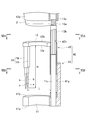
- Coupled mechanism 40 As shown in FIGS. 5 and 6, a pair of front and rear arms 11 and 12 are connected to the tip of the arm moving means 13, and the pair of front and rear arms 11 and 12 are connected by a connecting mechanism 40. That is, the front arm 11 and the rear arm 12 are coupled by the coupling mechanism 40 so as to be in a state in which mutual rotation in a plane perpendicular to the direction in which the front arm 11 and the rear arm 12 can approach and separate is fixed.
- a rear connection member 42 having a substantially shaft-like connection mechanism 40 formed in a substantially square cross section is provided at the proximal end of the rear arm 12.
- the rear connection member 42 is engaged with a front connection member 41 provided on the front arm 11.
- the front connection member 41 is provided with an engagement groove 41g, and the three inner surfaces of the engagement groove 41g are substantially in surface contact with the three outer surfaces of the rear connection member 42 (or a portion that is substantially surface contact is formed. (See FIG. 6).
- connection mechanism 40 is not limited to the configuration described above.
- the structure of the connection mechanism 40 should just be a structure which can be connected so that it may be in the state which the front side arm 11 and the rear side arm 12 can approach and separate, and the mutual rotation in the surface orthogonal to the direction which both approach and separate is fixed.
- a linear groove is provided in the front connection member 41 (or the rear connection member 42) along the axial direction, and a protrusion that engages with the linear groove is formed on the rear connection member 42 (or the front connection member 41). Even if it is provided, the same effect can be obtained.
- the rear arm 12 has a substantially strip shape, and the front surface 12a and the back surface 12b are formed on a flat surface parallel to each other.
- the strip shape here means a shape having a short width with respect to the length and a short thickness with respect to the length, and the strip shape is slightly curved along the length direction. It is a concept that includes both the ones that are present (see FIGS. 1 to 4) and those that are straight along the length direction.
- the distal end of the aforementioned sheath 13a is connected to the proximal end of the rear arm 12.
- the rear connection member 42 connected to the proximal end of the rear arm 12 is connected to the distal end of the sheath 13a.
- the rear arm 12 is connected to the sheath 13a so that the central axis of the sheath 13a and the front surface 12a and the back surface 12b of the rear arm 12 are orthogonal to each other at the connection portion with the sheath 13a.
- the direction of the central axis of the sheath 13a at the connecting portion between the sheath 13a and the rear arm 12 may be simply referred to as the central axis of the sheath 13a.
- connection member 42 of the connection mechanism 40 provided at the proximal end of the rear arm 12 is also disposed so that the axial direction thereof is substantially parallel to the central axis of the sheath 13a.
- a suture needle portion 14 is provided at the distal end portion of the rear arm 12.
- the suture needle portion 14 includes a pair of needle-like members 15 and 16 that are arranged along the axial direction of the rear arm 12.
- Each of the pair of needle-like members 15 and 16 has a shaft portion b and a portion (a twist-shaped portion a) provided at the tip of the shaft portion b and having a larger outer diameter than the tip.
- the edge-shaped part a is formed so that the outer diameter of the base end is larger than the outer diameter of the distal end of the shaft part b, and a step is formed at the connecting part with the shaft part b.
- the twist-like portion a is formed from the pair of needle-like members 15, 16. It has a role which prevents 21 and 21 falling off.
- the pair of needle-like members 15 and 16 of the suturing needle portion 14 are both in a state in which the tip thereof is directed to the front arm 11 and the axial direction thereof is orthogonal to the front surface 12a of the rear arm 12. 12 is attached.
- each of the pair of needle-like members 15 and 16 is attached to the rear arm 12 so that the central axis thereof is substantially parallel to the axial direction of the rear coupling member 42 (that is, the central axis of the sheath 13a). Yes.
- the front arm 11 As shown in FIG. 5, the front arm 11 has a substantially strip shape, and the front surface 11a and the back surface 11b are formed on a flat surface parallel to each other.
- the front arm 11 is formed substantially in the same shape as the rear arm 12.
- the front connection member 41 of the connection mechanism 40 described above is provided.
- the front arm 11 is connected to the tip of a wire 13b.
- a wire 13 b is inserted into a through-hole 42 h that penetrates the rear connection member 42 of the rear arm 12, and the distal end of the wire 13 b is provided at the proximal end portion of the front arm 11. It is connected to.
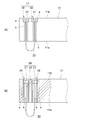
- a housing portion 17 having a pair of housing spaces 18 and 19 is formed at the tip of the front arm 11 (see FIG. 6). As shown in FIG. 7, the pair of housing spaces 18 and 19 of the housing portion 17 are through holes that penetrate between the front surface 11 a and the back surface 11 b of the front arm 11. Each of the pair of accommodating spaces 18 and 19 is formed such that the central axis thereof is parallel to the direction in which the pair of front and rear arms 11 and 12 approach and separate (that is, the direction parallel to the central axis of the sheath 13a). .
- Each of the pair of receiving spaces 18 and 19 is formed with an opening that communicates with the side surface of the front arm 11, and a suture 22 of a suturing instrument 20 to be described later passes through the opening into the pair of receiving spaces 18 and 19. You can go in and out.
- the pair of receiving spaces 18 and 19 are stepped holes in which the inner diameter of the back surface 11b side (large diameter portion a) is larger than the inner diameter of the front surface 11a side (small diameter portion b). And each accommodation space 18 and 19 is formed so that the internal diameter of the small diameter part b may become larger than the outer diameter of the edge-shaped part a, The reason formed in this shape is mentioned later.
- the pair of accommodating spaces 18 and 19 are provided so that the central axes thereof are substantially coaxial with the central axes of the pair of needle-like members 15 and 16, respectively.
- the central axis of the pair of receiving spaces 18 and 19 and the central axis of the pair of needle-like members 15 and 16 are substantially coaxial, respectively, when the pair of front and rear arms 11 and 12 are brought close to each other. , 19 is allowed to be displaced so that the pair of needle-like members 15, 16 of the suture needle portion 14 can be inserted.
- front and rear surfaces of the front arm 11 and the rear arm 12 are flat surfaces.
- front surface and the rear surface of the front arm 11 and the rear arm 12 are not necessarily flat surfaces.
- the position at which the pair of needle-like members 15 and 16 are provided on the rear arm 12 is not particularly limited. However, if the size of the rear arm 12 is within a range that does not hinder insertion into the body, the distance between the pair of needle-like members 15 and 16 and the coupling mechanism 40 should be a certain distance. There is an advantage that the distance from the edge to the stitching position can be increased. From this point of view, the position of the arm moving means 13 from the position of the connecting mechanism 40 (in other words, the position where the front arm 11 and the rear arm 12 are connected to the arm moving means 13) to the pair of needle-like members 15,16. The distance L (see FIG.
- the distance L for each of the pair of needle-like members 15 and 16 is equal to each other. However, when the distance L for the pair of needle-like members 15 and 16 is different from each other, It is preferable to be in the range.
- the material, length, and shaft diameter of the pair of needle-like members 15 and 16 are not particularly limited.
- the pair of needle-like members 15 and 16 can pierce the target to be stitched and penetrate the target, and can be pulled out of the target by moving the target in the reverse direction.
- Any material having a certain length and strength may be used.
- the length may be any length from the front surface of the rear arm 12 to the tip thereof so as to penetrate the stomach wall.
- the metal is preferable in terms of strength. More specifically, the length H (see FIG.
- the shaft diameter of the pair of needle-like members 15 and 16 is preferably about 1 to 2 mm as the shaft diameter at the tip of the shaft portion b (the connecting portion with the handle portion a), and the maximum diameter of the handle portion a. Is preferably about 0.1 to 1 mm larger than the shaft diameter of the tip of the shaft portion b.
- the suturing device 10 of this embodiment includes a suturing instrument 20.
- the suturing instrument 20 includes a pair of engaging members 21 and 21 formed in an annular shape, and a suture thread 22 that connects the pair of engaging members 21 and 21.
- the pair of engaging members 21 and 21 of the suturing instrument 20 are respectively disposed in the pair of housing spaces 18 and 19 of the housing portion 17 of the front arm 11.
- the through holes that pass through the front and back of the pair of engaging members 21 and 21 are holes that pass through the small diameter portion b of the pair of receiving spaces 18 and 19. It is formed in a size that can be arranged above. Specifically, the pair of engaging members 21, 21 is formed so that the outer diameter is smaller than the inner diameter of the large-diameter portion a of the pair of housing spaces 18, 19 and larger than the inner diameter of the small-diameter portion b ( (See FIG. 7B).
- the pair of engaging members 21 and 21 are disposed in the pair of housing spaces 18 and 19, there is only a slight gap between the outer edges of the pair of engaging members 21 and 21 and the inner surface of the large-diameter portion a.
- the pair of engaging members 21 and 21 are formed in such a size that they are not formed.
- the through-hole 21h of a pair of engaging members 21 and 21 can insert the twist-like part a of a pair of needle-like members 15 and 16, when the twist-like part a completely penetrates the through-hole 21h.
- the pair of engaging members 21 and 21 are formed so as not to fall out from the pair of needle-like members 15 and 16.
- the pair of engaging members 21, 21 has an inner diameter smaller than the outer diameter of the twisted portion a of the pair of needle-like members 15, 16, but the shaft portion b of the pair of needle-like members 15, 16. It is formed so that it may become larger than the shaft diameter of the front-end
- the material of the pair of engaging members 21 and 21 is not particularly limited. However, even if the through-hole 21h as described above is formed, the state where the pair of needle-like members 15 and 16 are engaged with each other can be maintained while the twisted portions a of the pair of needle-like members 15 and 16 are inserted.
- a material having various properties is preferable. That is, it is desirable that the pair of engaging members 21 and 21 be formed of a material that can be elastically deformed to some extent. For example, if a metal plate, a shaft member, or the like is used, the pair of engaging members 21 and 21 having the above-described properties can be formed.
- the twisted portions a of the pair of needle-like members 15 and 16 can be simultaneously inserted into the pair of engaging members 21 and 21 of the suturing instrument 20 disposed in the pair of receiving spaces 18 and 19. Then, if the front arm 11 and the rear arm 12 are brought close to each other until the entire handle portion a of the pair of needle-like members 15 and 16 is inserted into the small diameter portion b of the pair of accommodating spaces 18 and 19, a pair of needles The shaped members 15 and 16 can be passed through the pair of engaging members 21 and 21 up to the shaft portion b.
- the arm moving means 13 is operated to separate the front arm 11 and the rear arm 12 from each other, the pair of engaging members 21 and 21 together with the pair of needle-like members 15 and 16 are paired with the accommodating space. 18 and 19 can be separated.
- the suture thread 22 can be detached from the pair of storage spaces 18 and 19 through the openings described above.
- the suture thread can be obtained by moving the front arm 11 and the rear arm 12 close to and away from each other only once with the object placed between the front arm 11 and the rear arm 12. 22 can be passed through the object so that both ends are located on the same side of the object. In other words, the suture 22 can be passed through the object so that the portion between both ends of the suture 22 is caught by the object (see FIG. 8C).
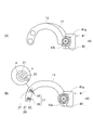
- the shaft 2 of the endoscope 1 to which the suturing device 10 of the present embodiment is attached is inserted into the stomach.
- the stomach wall at the site to be sutured is recessed inward by a method such as drawing inward with an endoscopic forceps inserted through the endoscope to form a protruding portion (protrusion PP) inside the stomach. .
- the arm moving means 13 is operated to separate the front arm 11 from the rear arm 12. Then, a gap is formed between the distal ends of the pair of needle-like members 15 and 16 of the suture needle portion 14 and the back surface 11b of the front arm 11 so as to sandwich the protruding portion PP.
- the shaft 2 is operated, and the protrusion PP is disposed in the gap between the distal ends of the pair of needle-like members 15 and 16 of the suture needle 14 and the back surface 11b of the front arm 11 (FIG. 8A). )).
- the arm moving means 13 is operated to move the rear arm 12 toward the front arm 11 with the movement of the front arm 11 fixed.
- the pair of needle-like members 15 and 16 of the suture needle portion 14 penetrates the protrusion PP, and the tips thereof are inserted into the pair of accommodating spaces 18 and 19, so that the pair of needle-like members 15 and 16 are twisted.
- the part a can be engaged with the pair of engaging members 21 and 21 of the suturing instrument 20 (FIG. 8B).
- FIG. 8B the case where the rear arm 12 is brought close to the front arm 11 when the rear arm 12 and the front arm 11 are brought close to each other has been described. You may make it approach, You may move both together and you may make both approach.
- the arm moving means 13 is operated to separate the rear arm 12 from the front arm 11.
- the pair of needle-like members 15 and 16 return to their original positions through the holes penetrating the protrusion PP.
- the pair of engaging members 21 and 21 to which both ends of the suture thread 22 are fixed are both positioned on one side (the upper side in FIG. 8C) of the protrusion PP.
- a ring is formed by the suture thread 22 from the needle-like member 15 through the protrusion PP and exiting to the opposite side of the needle-like member 15 and then passing through the protrusion PP and returning to the needle-like member 16 (see FIG. 8 (C)).
- the suture thread 22 is ligated in a state where the opposing wall surfaces of the projecting portion PP are in contact with each other.
- the part extending toward the protrusion PP is ligated.
- a commercially available clip or the like can be used.
- ligation can be performed.
- the tumor formed in the stomach wall can be excised by the following method without forming an opening in the stomach wall.
- the mucous membrane and the like around the tumor TM were excised, and the muscle layer was exposed so as to surround the tumor TM.
- a portion (exposed portion EA) is formed.
- the stomach wall (opposed wall OW) facing the exposed part EA and the part where the tumor TM is formed is connected by a suture SL or the like with the stomach slightly atrophied.
- a suturing device described in Japanese Patent No. 5294181 can be used for this connection.
- the connection of the exposed part EA and the opposing wall OW is implemented in at least two places.
- the exposed portion EA and the opposing wall OW are connected, carbon dioxide gas is supplied to the stomach to expand the stomach. Then, the tumor wall TW and the opposing wall OW are separated. At this time, since the exposed portion EA and the opposing wall OW are connected, expansion of the portion surrounded by the exposed portion EA (that is, the tumor TM) is limited as compared to the portion outside the exposed portion EA. That is, the tumor TM is in a state where it is suspended from the opposing wall OW by the suture thread SL (FIG. 9A).
- the stomach wall is recessed inward with the tumor TM portion as a vertex. Then, the position of the exposed portion EA can be sewn by the suturing device 10 of the present embodiment by the same method as the suturing of the protrusion PP as described above (FIG. 9B).
- the tumor TM can be excised by cutting the exposed portion EA at a position inside the stitched portion at the exposed portion EA. (FIG. 9C).
- the outer surfaces of the stomach wall are stitched together at the stitched portion, no opening is formed in the stomach wall. That is, since the tumor TM or the like can be removed without forming an opening in the stomach wall, it is possible to prevent the cancer cells from being seeded in the abdominal cavity even if the tumor TM is cancer.
- the suture needle portion 14 includes a pair of needle-like members 15 and 16, but the distance between the axes of the pair of needle-like members 15 and 16 is not particularly limited. What is necessary is just to be provided in the distance which can stitch
- the pair of needle-like members 15 and 16 of the suturing needle portion 14 are arranged along the axial direction of the rear arm 12 .
- the pair of needle-like members 15 and 16 may not necessarily be arranged along the axial direction.
- the rear arm 12 may be disposed so as to be inclined with respect to the axial direction or may be disposed so as to be orthogonal to each other.
- the pair of housing spaces 18 and 19 of the housing portion 17 of the front arm 11 are disposed so as to correspond to the pair of needle-like members 15 and 16 of the suture needle portion 14.
- a plurality of suture needle portions 14 may be provided side by side along the axial direction of the rear arm 12. In this case, a plurality of locations can be sewn at the same time by moving the front arm 11 and the rear arm 12 close and apart once. Then, even when a plurality of stitches are required, the stitches can be performed in a short time.
- suture needle portion 14 every time one suture is performed, it is necessary to replace the suturing device 10 and to fill the pair of storage spaces 18 and 19 of the storage portion 17 with the suture instrument 20.
- the suturing time becomes longer for the work.
- a plurality of suture needle portions 14 are arranged along the axial direction of the rear arm 12, a plurality of locations can be sewn at a time, so that the suturing time can be shortened. Specifically, if two suture needle portions 14 are provided, the suture can be completed in approximately half the time compared to the case where the suture needle portion 14 is provided in one place. As a result, the burden on the patient and the practicing doctor can be reduced.
- the number of accommodating portions 17 corresponding to the suture needle portions 14 is provided so as to correspond to the pair of needle-like members 15 and 16 of each suture needle portion 14.
- the accommodation spaces 18 and 19 of each accommodation part 17 are arranged.
- the suturing device of the present invention is suitable as a device for suturing tissues in the digestive tract.
Landscapes
- Health & Medical Sciences (AREA)
- Life Sciences & Earth Sciences (AREA)
- Surgery (AREA)
- Heart & Thoracic Surgery (AREA)
- Engineering & Computer Science (AREA)
- Biomedical Technology (AREA)
- Nuclear Medicine, Radiotherapy & Molecular Imaging (AREA)
- Medical Informatics (AREA)
- Molecular Biology (AREA)
- Animal Behavior & Ethology (AREA)
- General Health & Medical Sciences (AREA)
- Public Health (AREA)
- Veterinary Medicine (AREA)
- Surgical Instruments (AREA)
Abstract
Description
もし、胃壁などに開口を形成せずに癌等の組織を切除することができれば、より安全に軟性内視鏡によって消化管腔内から組織の切除などをできるので、かかる方法を実現する機器の開発が望まれている。
第2発明の縫合装置は、第1発明において、前記前側アームおよび前記後側アームが前記アーム移動手段に連結されている位置から、前記一対の針状部材までの、前記後側アームと前記前側アームが接近離間する方向と垂直な面に沿った距離が、5mm以上であることを特徴とする。
第3発明の縫合装置は、第1または第2発明において、前記縫合針部は、前記一対の針状部材が前記後側アームの軸方向に並ぶように設けられており、前記収容部は、前記一対の収容空間が前記前側アームの軸方向に並ぶように設けられていることを特徴とする。
第4発明の縫合装置は、第1、第2または第3発明において、前記後側アームには、該後側アームの軸方向に並ぶように複数の前記縫合針部が設けられており、前記前側アームには、該前側アームの軸方向に並ぶように各縫合針部に対応する複数の前記収容部が設けられていることを特徴とする。
第5発明の縫合装置は、第1、第2、第3または第4発明において、前記後側アームと前記前側アームを、接近離間可能かつ接近離間する方向と直交する面内の相互回転を固定した状態で連結する連結機構を備えていることを特徴とする。
第2、第3発明によれば、幅や長さのある組織の縫合が可能となる。
第4発明によれば、複数個所の縫合を同時にできるので、縫合作業を迅速に行うことができる。
第5発明によれば、前側アームと後側アームを接近させた際に、一対の針状部材の先端部を一対の収容空間内に確実に収容させることができる。
本発明の縫合装置は、軟性内視鏡に取り付けて、消化管腔内から縫合を行う装置であって、簡便かつ迅速に縫合を実施できるようにしたことに特徴を有している。
なお、装置各部の構造を分かりやすくするために、各図面における各部の相対的なサイズなどは必ずしも実際の装置におけるサイズとは対応させていない。
図1において、符号2は、本実施形態の縫合装置10が取り付けられる内視鏡1のシャフトを示している。本実施形態の縫合装置10が取り付けられる内視鏡1は、一般的な内視鏡手術に使用される軟性内視鏡である。この内視鏡のシャフト2は、生体の消化管に挿入して使用されるものであれば、その径や長さ、材質などはとくに限定されない。例えば、シャフト2の径は、一般的な内視鏡では10mm程度であるが、5~15mm程度のものでもよい。また、シャフト2の長さは、一般的な内視鏡では1200mm程度であるが、1200~3000mm程度のものでもよい。
図1に示すように、本実施形態の縫合装置10(以下、単に縫合装置10という場合がある)は、前後一対のアーム11,12と、この前後一対のアーム11,12を作動させるアーム移動手段13と、前後一対のアーム11,12の移動を案内する連結機構40と、を備えている。
図1~図4に示すように、アーム移動手段13は、軸方向に沿って延びた長尺な部材であり、内視鏡1のシャフト2に取り付けられるものである。このアーム移動手段13の長さは、内視鏡1のシャフト2の長さと同程度の長さであればよく、とくに限定されない。
図5および図6に示すように、アーム移動手段13の先端には、前後一対のアーム11,12が連結されており、前後一対のアーム11,12は連結機構40によって連結されている。つまり、前側アーム11と後側アーム12は、連結機構40によって、接近離間可能かつ接近離間する方向と直交する面内の相互回転を固定した状態となるように連結されている。
つぎに、前後一対のアーム11,12を説明する。
まず、後側アーム12について説明する。
図5に示すように、後側アーム12は、略短冊状であって前面12aと背面12bが互いに平行な平坦面に形成されたものである。ここでいう短冊状とは、長さに対して幅が短く、また、厚さも長さに対して短い形状のものを意味しており、短冊状には、長さ方向に沿って若干湾曲しているもの(図1~図4参照)と、長さ方向に沿って真っ直ぐなものの両方を含む概念である。
一方、後側アーム12の先端部には、縫合針部14が設けられている。この縫合針部14は、後側アーム12の軸方向に沿って並ぶように配置された、一対の針状部材15,16を備えている。一対の針状部材15,16は、いずれも軸部bと、この軸部bの先端に設けられた、この先端よりも外径が大きい部分(やじり状部a)とを有している。やじり状部aは、その基端の外径が軸部bの先端の外径よりも大きく、軸部bとの連結部分に段差ができるように形成されている。このやじり状部aは、後述するように、一対の針状部材15,16が一対の係合部材21,21と係合した際に、一対の針状部材15,16から一対の係合部材21,21が脱落することを防ぐ役割を有する。
図5に示すように、前側アーム11は、略短冊状であって前面11aと背面11bが互いに平行な平坦面に形成されたものである。この前側アーム11は、実質的に、後側アーム12と同じ形状に形成されている。この前側アーム11の基端部には、前述した連結機構40の前側連結部材41が設けられている。
また、図7に示すように、本実施形態の縫合装置10は、縫合器具20を備えている。この縫合器具20は、円環状に形成された一対の係合部材21,21と、一対の係合部材21,21を連結する縫合糸22と、から構成されている。
以上のごとき構成であるので、本実施形態の縫合装置10では、アーム移動手段13を操作して前側アーム11と後側アーム12を接近させれば、一対の針状部材15,16を、同時に一対の収容空間18,19に挿入することができる。
上記のごとき構成を有するので、本実施形態の縫合装置10を内視鏡1のシャフト2に取り付けておけば、胃壁などの組織を胃の内部から縫合することができる。
また、本実施形態の縫合装置1を使用すれば、以下のような方法で、胃壁内に形成された腫瘍を胃壁に開口を形成することなく、切除することができる。
縫合針部14は一対の針状部材15,16を備えているが、一対の針状部材15,16の軸間距離は、とくに限定されない。縫合糸22によって縫合部分を適切に縫合できる程度の距離に設けられていればよい。例えば、2~4mm程度にしておけば、外科手術における縫合と同等程度の縫合状態を実現することが可能となる。
2 シャフト
10 縫合装置
11 前側アーム
12 後側アーム
13 アーム移動手段
14 針状部
15 針状部材
16 針状部材
17 収容部
18 収容空間
19 収容空間
20 縫合器具
21 係合部材
22 縫合糸
40 連結機構
41 前側連結部材
41g 係合溝
42 後側連結部材
PP 突起部
TM 腫瘍
Claims (5)
- 前側アームと、
該前側アームに対し接近離間可能に設けられた後側アームと、
前記前側アームと前記後側アームを接近離間させるアーム移動手段と、を備えており、
前記前側アームおよび前記後側アームは、基端部が前記アーム移動手段に連結されており、
前記後側アームは、
先端を前記前側アームに向けた状態かつその中心軸が該後側アームと前記前側アームが接近離間する方向と平行になるように設けられた一対の針状部材を有する縫合針部を備えており、
前記前側アームは、
該前側アームと前記後側アームが接近したときに、前記一対の針状部材の先端部をそれぞれ収容し得る一対の収容空間が設けられた収容部を備えており、
該収容部の一対の収容空間内には、
縫合糸によって互いに連結された、前記針状部材と係合可能な一対の係合部材が収容されている
ことを特徴とする縫合装置。 - 前記前側アームおよび前記後側アームが前記アーム移動手段に連結されている位置から、前記一対の針状部材までの、前記後側アームと前記前側アームが接近離間する方向と垂直な面に沿った距離が5mm以上である
ことを特徴とする請求項1記載の縫合装置。 - 前記縫合針部は、
前記一対の針状部材が前記後側アームの軸方向に並ぶように設けられており、
前記収容部は、
前記一対の収容空間が前記前側アームの軸方向に並ぶように設けられている
ことを特徴とする請求項1または2記載の縫合装置。 - 前記後側アームには、該後側アームの軸方向に並ぶように複数の前記縫合針部が設けられており、
前記前側アームには、該前側アームの軸方向に並ぶように各縫合針部に対応する複数の前記収容部が設けられている
ことを特徴とする請求項1、2または3記載の縫合装置。 - 前記後側アームと前記前側アームを、接近離間可能かつ接近離間する方向と直交する面内の相互回転を固定した状態で連結する連結機構を備えている
ことを特徴とする請求項1、2、3または4記載の縫合装置。
Priority Applications (3)
| Application Number | Priority Date | Filing Date | Title |
|---|---|---|---|
| CN201780019926.7A CN108882931B (zh) | 2016-03-24 | 2017-03-24 | 缝合装置 |
| EP17770399.8A EP3434199A4 (en) | 2016-03-24 | 2017-03-24 | SEAM DEVICE |
| JP2018507435A JP6909468B2 (ja) | 2016-03-24 | 2017-03-24 | 縫合装置 |
Applications Claiming Priority (2)
| Application Number | Priority Date | Filing Date | Title |
|---|---|---|---|
| JP2016060880 | 2016-03-24 | ||
| JP2016-060880 | 2016-03-24 |
Publications (1)
| Publication Number | Publication Date |
|---|---|
| WO2017164359A1 true WO2017164359A1 (ja) | 2017-09-28 |
Family
ID=59900566
Family Applications (1)
| Application Number | Title | Priority Date | Filing Date |
|---|---|---|---|
| PCT/JP2017/011974 Ceased WO2017164359A1 (ja) | 2016-03-24 | 2017-03-24 | 縫合装置 |
Country Status (4)
| Country | Link |
|---|---|
| EP (1) | EP3434199A4 (ja) |
| JP (1) | JP6909468B2 (ja) |
| CN (1) | CN108882931B (ja) |
| WO (1) | WO2017164359A1 (ja) |
Cited By (2)
| Publication number | Priority date | Publication date | Assignee | Title |
|---|---|---|---|---|
| JP2019177049A (ja) * | 2018-03-30 | 2019-10-17 | 日本ゼオン株式会社 | 医療用縫合装置 |
| JP2022156725A (ja) * | 2021-03-31 | 2022-10-14 | 日本ゼオン株式会社 | 縫合装置 |
Families Citing this family (3)
| Publication number | Priority date | Publication date | Assignee | Title |
|---|---|---|---|---|
| CN113440188A (zh) * | 2021-05-25 | 2021-09-28 | 张强 | 栓形缝合器、栓形缝合机构、栓形缝合装置及内镜缝合方法 |
| CN113440187A (zh) * | 2021-05-25 | 2021-09-28 | 张强 | 钉形缝合器、钉形缝合机构、钉形缝合装置及内镜缝合方法 |
| CN113558697A (zh) * | 2021-09-08 | 2021-10-29 | 张强 | 钉形缝合器、钉形缝合装置及内镜缝合方法 |
Citations (3)
| Publication number | Priority date | Publication date | Assignee | Title |
|---|---|---|---|---|
| US20060167476A1 (en) * | 2000-11-06 | 2006-07-27 | Perclose, Inc | Systems, devices and methods for suturing patient tissue |
| JP2010136733A (ja) * | 2008-12-09 | 2010-06-24 | Hirohito Yoshida | 内視鏡用縫合装置及び内視鏡用縫合装置を用いて行う胃壁切開部縫合方法 |
| JP5294181B2 (ja) * | 2011-01-25 | 2013-09-18 | 国立大学法人 香川大学 | 縫合装置 |
Family Cites Families (4)
| Publication number | Priority date | Publication date | Assignee | Title |
|---|---|---|---|---|
| US6117144A (en) * | 1995-08-24 | 2000-09-12 | Sutura, Inc. | Suturing device and method for sealing an opening in a blood vessel or other biological structure |
| US6551330B1 (en) * | 2000-09-21 | 2003-04-22 | Opus Medical, Inc. | Linear suturing apparatus and methods |
| US7618425B2 (en) * | 2002-01-30 | 2009-11-17 | Olympus Corporation | Endoscopic suturing system |
| CN103976769B (zh) * | 2014-05-21 | 2015-12-30 | 上海理工大学 | 荷包缝合器及其操作方法 |
-
2017
- 2017-03-24 WO PCT/JP2017/011974 patent/WO2017164359A1/ja not_active Ceased
- 2017-03-24 EP EP17770399.8A patent/EP3434199A4/en active Pending
- 2017-03-24 CN CN201780019926.7A patent/CN108882931B/zh active Active
- 2017-03-24 JP JP2018507435A patent/JP6909468B2/ja active Active
Patent Citations (3)
| Publication number | Priority date | Publication date | Assignee | Title |
|---|---|---|---|---|
| US20060167476A1 (en) * | 2000-11-06 | 2006-07-27 | Perclose, Inc | Systems, devices and methods for suturing patient tissue |
| JP2010136733A (ja) * | 2008-12-09 | 2010-06-24 | Hirohito Yoshida | 内視鏡用縫合装置及び内視鏡用縫合装置を用いて行う胃壁切開部縫合方法 |
| JP5294181B2 (ja) * | 2011-01-25 | 2013-09-18 | 国立大学法人 香川大学 | 縫合装置 |
Non-Patent Citations (1)
| Title |
|---|
| See also references of EP3434199A4 * |
Cited By (3)
| Publication number | Priority date | Publication date | Assignee | Title |
|---|---|---|---|---|
| JP2019177049A (ja) * | 2018-03-30 | 2019-10-17 | 日本ゼオン株式会社 | 医療用縫合装置 |
| JP7056324B2 (ja) | 2018-03-30 | 2022-04-19 | 日本ゼオン株式会社 | 医療用縫合装置 |
| JP2022156725A (ja) * | 2021-03-31 | 2022-10-14 | 日本ゼオン株式会社 | 縫合装置 |
Also Published As
| Publication number | Publication date |
|---|---|
| JPWO2017164359A1 (ja) | 2019-04-11 |
| CN108882931A (zh) | 2018-11-23 |
| EP3434199A4 (en) | 2019-11-13 |
| CN108882931B (zh) | 2021-06-25 |
| JP6909468B2 (ja) | 2021-07-28 |
| EP3434199A1 (en) | 2019-01-30 |
Similar Documents
| Publication | Publication Date | Title |
|---|---|---|
| JP5294181B2 (ja) | 縫合装置 | |
| US9706999B2 (en) | Method for tissue resection | |
| JP4563446B2 (ja) | 胃の処置システム | |
| EP1938761B1 (en) | Suturing device | |
| US8480689B2 (en) | Suturing device | |
| US20110112434A1 (en) | Kits and procedures for natural orifice translumenal endoscopic surgery | |
| JP2007185495A (ja) | オーバーチューブ | |
| JP5224298B2 (ja) | 管腔壁穿刺用オーバーチューブ | |
| US20070255296A1 (en) | Medical instrument to place a pursestring suture, open a hole and pass a guidewire | |
| JP2007090062A (ja) | 縫合具 | |
| JP2010005386A (ja) | 内視鏡的ステッチング装置 | |
| JP6909468B2 (ja) | 縫合装置 | |
| JP2007296351A (ja) | 三重に曲がる括約筋切開器 | |
| CN116367784B (zh) | 管腔粘连或伤口缺陷的抓持系统和方法 | |
| JP2012024607A (ja) | 縫合器 | |
| CN117064473B (zh) | 吻合口加固修补片 | |
| JP5372301B1 (ja) | 医療用ポート | |
| JP6755498B2 (ja) | 縫合装置 | |
| JP7077964B2 (ja) | 縫合装置 | |
| JPWO2019189400A1 (ja) | 内視鏡用外付けチューブ部材 | |
| US20240081796A1 (en) | Full-thickness resection method | |
| JP2022156725A (ja) | 縫合装置 | |
| JP7079450B2 (ja) | 縫合装置 | |
| JP2025504207A (ja) | 糸縫合内視鏡デバイス | |
| US20210059659A1 (en) | Devices and methods for closure of openings in tissue |
Legal Events
| Date | Code | Title | Description |
|---|---|---|---|
| WWE | Wipo information: entry into national phase |
Ref document number: 2018507435 Country of ref document: JP |
|
| NENP | Non-entry into the national phase |
Ref country code: DE |
|
| WWE | Wipo information: entry into national phase |
Ref document number: 2017770399 Country of ref document: EP |
|
| ENP | Entry into the national phase |
Ref document number: 2017770399 Country of ref document: EP Effective date: 20181024 |
|
| 121 | Ep: the epo has been informed by wipo that ep was designated in this application |
Ref document number: 17770399 Country of ref document: EP Kind code of ref document: A1 |