WO2017164395A1 - 銅合金及びその製造方法 - Google Patents
銅合金及びその製造方法 Download PDFInfo
- Publication number
- WO2017164395A1 WO2017164395A1 PCT/JP2017/012128 JP2017012128W WO2017164395A1 WO 2017164395 A1 WO2017164395 A1 WO 2017164395A1 JP 2017012128 W JP2017012128 W JP 2017012128W WO 2017164395 A1 WO2017164395 A1 WO 2017164395A1
- Authority
- WO
- WIPO (PCT)
- Prior art keywords
- copper alloy
- phase
- experimental example
- βcusn
- producing
- Prior art date
- Legal status (The legal status is an assumption and is not a legal conclusion. Google has not performed a legal analysis and makes no representation as to the accuracy of the status listed.)
- Ceased
Links
Images


Classifications
-
- C—CHEMISTRY; METALLURGY
- C22—METALLURGY; FERROUS OR NON-FERROUS ALLOYS; TREATMENT OF ALLOYS OR NON-FERROUS METALS
- C22C—ALLOYS
- C22C9/00—Alloys based on copper
- C22C9/02—Alloys based on copper with tin as the next major constituent
-
- C—CHEMISTRY; METALLURGY
- C22—METALLURGY; FERROUS OR NON-FERROUS ALLOYS; TREATMENT OF ALLOYS OR NON-FERROUS METALS
- C22C—ALLOYS
- C22C9/00—Alloys based on copper
- C22C9/05—Alloys based on copper with manganese as the next major constituent
-
- C—CHEMISTRY; METALLURGY
- C22—METALLURGY; FERROUS OR NON-FERROUS ALLOYS; TREATMENT OF ALLOYS OR NON-FERROUS METALS
- C22F—CHANGING THE PHYSICAL STRUCTURE OF NON-FERROUS METALS AND NON-FERROUS ALLOYS
- C22F1/00—Changing the physical structure of non-ferrous metals or alloys by heat treatment or by hot or cold working
- C22F1/006—Resulting in heat recoverable alloys with a memory effect
-
- C—CHEMISTRY; METALLURGY
- C22—METALLURGY; FERROUS OR NON-FERROUS ALLOYS; TREATMENT OF ALLOYS OR NON-FERROUS METALS
- C22F—CHANGING THE PHYSICAL STRUCTURE OF NON-FERROUS METALS AND NON-FERROUS ALLOYS
- C22F1/00—Changing the physical structure of non-ferrous metals or alloys by heat treatment or by hot or cold working
- C22F1/08—Changing the physical structure of non-ferrous metals or alloys by heat treatment or by hot or cold working of copper or alloys based thereon
-
- C—CHEMISTRY; METALLURGY
- C22—METALLURGY; FERROUS OR NON-FERROUS ALLOYS; TREATMENT OF ALLOYS OR NON-FERROUS METALS
- C22C—ALLOYS
- C22C9/00—Alloys based on copper
- C22C9/01—Alloys based on copper with aluminium as the next major constituent
Definitions
- the invention disclosed in this specification relates to a copper alloy and a manufacturing method thereof.
- Non-Patent Documents 1 and 2 copper alloys having shape memory characteristics have been proposed (for example, see Non-Patent Documents 1 and 2).
- Examples of such copper alloys include Cu—Zn alloys, Cu—Al alloys, Cu—Sn alloys, and the like.
- Each of these copper-based memory alloys has a parent phase called a ⁇ phase (a phase having a crystal structure related to bcc) that is stable at high temperatures, and this parent phase has a regular arrangement of alloy elements. .
- ⁇ phase a phase having a crystal structure related to bcc
- Cu—Zn—Al, Cu—Zn—Sn, Cu—Al—Mn based copper alloys are inexpensive and advantageous in terms of raw material price, but are general shape memory alloys.
- the recovery rate was not as high as that of the Ni—Ti alloy.
- This Ni—Ti alloy also exhibits excellent SME characteristics, that is, a high recovery rate, but is expensive because it contains a large amount of Ti, has low heat and electrical conductivity, and can only be used at a low temperature of 100 ° C. or less. could not.
- the Cu—Sn alloy has a problem that the internal structure changes with time due to aging at room temperature, and the shape memory characteristics change.
- Sn diffusion occurs due to aging at room temperature, and Sn-rich s phase or L phase with coarse s phase precipitates, and shape memory characteristics may easily change.
- the s phase and L phase are Sn-rich phases, and there is a possibility of precipitates such as ⁇ CuSn, ⁇ CuSn, and ⁇ CuSn due to the progress of eutectoid transformation.
- Cu-Sn alloys have large changes over time in properties such as the transformation temperature changes drastically when left at a relatively low temperature near room temperature. There wasn't. Thus, copper alloys exhibiting stress-induced martensitic transformation that reversely transform in a high temperature range of about 500 to 700 ° C. have not been put into practical use.
- the invention of the present disclosure has been made to solve such problems, and provides a novel copper alloy that stably exhibits shape memory characteristics in a Cu—Sn alloy and a method for producing the same. Main purpose.
- the copper alloy and the manufacturing method thereof disclosed in this specification have taken the following measures in order to achieve the above-described main object.
- the copper alloy disclosed herein is: A 100-base alloy composition Cu (x + y) Sn x Mn y (where satisfy 8 ⁇ x ⁇ 16,2 ⁇ y ⁇ 10), the ⁇ CuSn phase Mn is a solid solution as a main phase, the ⁇ CuSn phase Is martensitic transformed by heat treatment or processing.
- the method for producing a copper alloy disclosed in this specification includes: A method for producing a copper alloy that undergoes martensitic transformation by heat treatment or processing, A raw material containing Cu, Sn and Mn and having a basic alloy composition of Cu 100- (x + y) Sn x M y (where 8 ⁇ x ⁇ 16, 2 ⁇ y ⁇ 10) is melt cast and cast A casting process to obtain; At least the casting step is included in a homogenization step in which the cast material is homogenized in the temperature range of the ⁇ CuSn phase to obtain a homogenized material.
- the copper alloy and its manufacturing method of the present disclosure can provide a novel Cu—Sn based copper alloy that stably expresses shape memory characteristics and a manufacturing method thereof.
- the reason why such an effect is obtained is assumed as follows, for example.
- the additive element Mn makes the ⁇ phase of the alloy more stable at room temperature.
- the addition of Mn suppresses slip deformation due to dislocations and inhibits plastic deformation, thereby further improving the recovery rate.
- the computational state figure of Mn 5.0at% of a CuSnMn type alloy.
- the computational phase diagram of Mn 8.3at% of a CuSnMn type alloy.
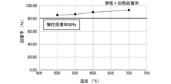
- the optical microscope observation result of the alloy foil of Experimental example 3. The relationship figure of each temperature and the elasticity + heating recovery rate of Experimental example 3.
- the XRD measurement result of Experimental example 1. The XRD measurement result of Experimental example 2.
- the optical microscope observation result of the alloy foil of Experimental example 7-2 air cooling).
- the optical microscope observation result of the alloy foil of Experimental example 7-3 (oil cooling).
- the optical microscope observation result of the alloy foil of Experimental example 7-4 (water cooling).
- the optical microscope observation result of the alloy foil of Experimental example 7-5 (-90 degreeC cooling).
- XRD measurement result of Experimental Example 7-3 (oil-cooled).
- the XRD measurement result of Experimental example 7-4 water cooling).
- XRD measurement result of Experimental Example 7-6 room temperature aging after water cooling).
- Copper alloy disclosed herein is 100- basic alloy composition Cu (x + y) (satisfy where 8 ⁇ x ⁇ 16,2 ⁇ y ⁇ 10) Sn x Mn y, Mn is solid-solved
- the ⁇ CuSn phase is the main phase, and the ⁇ CuSn phase undergoes martensitic transformation by heat treatment or processing.
- the main phase refers to a phase that is contained most in the whole, for example, a phase that is contained in an amount of 50% by mass or more, a phase that is contained in an amount of 80% by mass or more, or 90% by mass or more. It is good also as an included phase.
- the ⁇ CuSn phase is contained in an amount of 95% by mass or more, more preferably 98% by mass or more.
- the copper alloy is cooled after being treated at a temperature of 500 ° C. or higher, and may have one or more of a shape memory effect and a superelastic effect at a temperature lower than the melting point.
- this copper alloy since the main phase is a ⁇ CuSn phase, a shape memory effect and a superelastic effect can be exhibited.
- this copper alloy may include a ⁇ CuSn phase in an area ratio of 50% or more and 100% or less in surface observation. Thus, the main phase may be obtained by surface observation.
- the area ratio of the ⁇ CuSn phase may be 95% or more, more preferably 98% or more.
- This copper alloy most preferably contains the ⁇ CuSn phase as a single phase, but may contain other phases.
- This copper alloy may contain Sn in the range of 8 at% or more and 16 at% or less, Mn in the range of 2 at% or more and 10 at% or less, and the balance may be Cu and inevitable impurities.
- Mn is contained at 2 at% or more, the self-recovery rate can be further increased.
- Mn is contained at 10 at% or less, it is possible to further suppress a decrease in conductivity, a decrease in self-recovery rate, and the like.
- the Mn content is preferably 2.5 at% or more, and more preferably 3.0 at% or more. Further, the Mn content is preferably 8.3 at% or less, and more preferably 7.5 at% or less.
- the self-recovery rate can be further increased.
- the self-recovery rate can be further increased.
- the self-recovery rate can be further increased.
- the self-recovery rate can be further increased.
- the self-recovery rate can be further increased.
- the self-recovery rate can be further increased.
- the self-recovery rate can be further increased.
- the self-recovery rate can be further increased.
- the self-recovery rate can be further increased.
- the self-recovery rate can be further increased.
- the self-recovery rate can be further increased.
- the self-recovery rate can be further increased.
- the self-recovery rate can be further increased.
- the self-recovery rate can be further increased.
- the self-recovery rate can be further increased.
- the self-recovery rate can be further increased.
- the self-recovery rate can be further increased.
- the self-recovery rate can be further increased.
- This copper alloy after bent at an angle theta 0 bending a plate-like copper alloy, it is preferable elastic recovery rate as determined by the angle theta 1 when the unloading (%) is 40% or more.
- the elastic recovery rate is preferably 40% or more.
- the elastic recovery rate is 18% or more, it can be determined that there was recovery (shape memory characteristics) due to reverse transformation of martensite, not mere plastic deformation.
- This elastic recovery rate is preferably higher, for example, preferably 45% or more, and more preferably 50% or more. It is assumed that the bending angle ⁇ 0 is 90 °.
- Elastic recovery rate R E [%] (1 ⁇ 1 / ⁇ 0 ) ⁇ 100 (Formula 1)
- the heat recovery rate is preferably 40% or more.
- the heating recovery rate may be obtained from the following equation using the angle ⁇ 1 at the time of unloading. This heat recovery rate is preferably higher, for example, preferably 45% or more, and more preferably 50% or more.
- the heat treatment to be recovered is preferably performed, for example, in the range of 500 ° C. or higher and 800 ° C. or lower.
- the heat treatment time depends on the shape and size of the copper alloy, but may be a short time, for example, 10 seconds or less.
- Heat recovery rate R T [%] (1 ⁇ 2 / ⁇ 1 ) ⁇ 100 (Formula 2)
- This copper alloy is obtained from an angle ⁇ 1 when a flat copper alloy is bent at a bending angle ⁇ 0 and then unloaded, and further an angle ⁇ 2 when heated to a predetermined recovery temperature determined based on the ⁇ CuSn phase.
- the elastic heat recovery rate (%) is preferably 45% or more.
- the elastic heat recovery rate is preferably 45% or more.
- the elastic heat recovery rate [%] may be obtained from the following equation using the average elastic recovery rate. This elastic heat recovery rate is preferably higher, for example, preferably 50% or more, more preferably 60% or more, still more preferably 70% or more, and 80% or more. Is still more preferred.
- the elastic heat recovery rate is more preferably 85% or more, and still more preferably 90% or more.
- Elastic heat recovery rate R E + T [%] Average elastic recovery rate + (1 ⁇ 2 / ⁇ 1 ) ⁇ (1 ⁇ average elastic recovery rate) (Equation 3)
- This copper alloy may be made of polycrystal or single crystal.
- This copper alloy may have a crystal grain size of 100 ⁇ m or more.
- the crystal grain size is more preferably larger, and more preferably a single crystal than a polycrystal. This is because the shape memory effect and the superelastic effect are easily exhibited.
- the copper alloy is preferably a homogenized material obtained by homogenizing a cast material.
- the cast copper alloy is preferably subjected to a homogenization treatment because a solidified structure may remain.
- This copper alloy has an Ms point (starting temperature of martensite transformation during cooling) and an As point (starting temperature of reverse transformation from martensite to ⁇ CuSn phase) depending on the contents of Sn and Mn. It is good. In this copper alloy, the Ms point and the As point change depending on the Mn content, and thus various adjustments such as a manifestation effect are easily performed.
- This manufacturing method is a method for manufacturing a copper alloy that undergoes martensitic transformation by heat treatment or processing, and includes at least a casting step among a casting step and a homogenization step.
- the casting process dissolving the raw material base alloy composition comprising Cu and Sn and Mn is Cu 100- (x + y) (satisfy where 8 ⁇ x ⁇ 16,2 ⁇ y ⁇ 10) Sn x Mn y casting To obtain a cast material. At this time, it is good also as what obtains the casting material which melt-casts a raw material and makes (beta) CuSn phase a main phase.
- raw materials for Cu, Sn, and Mn for example, these simple substances or alloys containing two or more of them can be used. Moreover, what is necessary is just to adjust the compounding ratio of a raw material according to a desired basic alloy composition.
- the dissolution method is not particularly limited, but the high-frequency dissolution method is preferable because it is efficient and can be industrially used.
- the casting process is preferably performed in an inert atmosphere such as nitrogen, Ar, or vacuum. Oxidation of the casting can be further suppressed.
- a cooling rate as high as possible is preferable for obtaining a stable ⁇ CuSn phase.
- the cooling method include air cooling, oil cooling, and water cooling, and water cooling is preferable.
- the cast material is homogenized within the temperature range of the ⁇ CuSn phase to obtain a homogenized material.
- the cast material is held in a temperature range of 600 ° C. or higher and 850 ° C. or lower and then cooled at a cooling rate of ⁇ 50 ° C./s to ⁇ 500 ° C./s.
- a cooling rate as high as possible is preferable for obtaining a stable ⁇ CuSn phase.
- the homogenization temperature is more preferably 650 ° C. or higher, and still more preferably 700 ° C. or higher. Further, the homogenization temperature is more preferably 800 ° C.
- the homogenization time may be, for example, 20 minutes or longer, or 30 minutes or longer.
- the homogenization time may be 48 hours or less, for example, or 24 hours or less.
- the homogenization treatment is also preferably performed in an inert atmosphere such as nitrogen, Ar, or vacuum.
- the manufacturing method of a copper alloy is cold working or hot working to one or more of a plate shape, a foil shape, a rod shape, a linear shape, and a predetermined shape with respect to one or more of a cast material and a homogenized material.
- One or more processing steps may be further included.
- hot processing may be performed in a temperature range of 500 ° C. or higher and 700 ° C. or lower, and then cooled at a cooling rate of ⁇ 50 ° C./s to ⁇ 500 ° C./s.
- the cross-section reduction rate may be processed at 50% or less by a method for suppressing the occurrence of shear deformation.
- the method for producing a copper alloy may further include an aging step of performing an age hardening treatment on one or more of the cast material and the homogenized material to obtain an age hardened material.
- the manufacturing method of a copper alloy is good also as what further includes the ordering process which performs an ordering process with respect to 1 or more among casting materials and a homogenization material, and obtains an ordering material.
- the age hardening treatment or the ordering treatment may be performed in a temperature range of 100 ° C. to 400 ° C. and a time range of 0.5 h to 24 h.
- the present disclosure described above in detail can provide a novel Cu—Sn-based copper alloy that stably exhibits shape memory characteristics and a method for producing the same.
- the reason why such an effect is obtained is assumed as follows, for example.
- the additive element Mn makes the ⁇ phase of the alloy more stable at room temperature.
- the addition of Mn suppresses slip deformation due to dislocation and inhibits plastic deformation, thereby further improving the recovery rate.
- CuSn-based alloys have good castability, and the eutectoid point of ⁇ CuSn is considered to be unlikely to cause eutectoid transformation that is a cause of deterioration of shape memory characteristics due to high temperature.
- it has been studied to develop and control the shape memory characteristics by adding the third additive element X (Mn) of the CuSn-based alloy.
- Example 1 A Cu—Sn—Mn alloy was produced.
- a composition in which the constituent phase of the target sample at a high temperature is a ⁇ CuSn single phase was set as a target composition.
- the reference phase diagram is an experimental phase diagram by ASM International DESK HANDBOOK Phase Diagrams for Binary Alloys Second Edition (5) and ASM International Handbook of Ternary Alloy Phase Diagrams.
- a computational phase diagram by Thermo-Calc which is software for creating an equilibrium phase diagram by the CALPHAD method, was also used.
- the sample was vacuum-sealed in a quartz tube, held in a muffle furnace at 700 ° C. (973 K) for 30 minutes, then placed in ice water and rapidly cooled, and at the same time, the quartz tube was broken.
- the alloy ingot is cut into a thickness of 0.2 to 0.3 mm using a fine cutter and a micro cutter, and mechanically polished with a rotary sander to which water resistant abrasive paper No. 100 to 2000 is attached. .3 ⁇ m) to obtain a mirror surface. Since the optical microscope observation sample is also handled as a bending test sample, heat treatment (homogenization treatment) was performed after adjusting the sample thickness. The sample thickness was 0.15 mm.
- a Keyence digital microscope VH-8000 was used for the optical microscope observation. The enlargement magnification of this apparatus is 450 to 3000 times, but observation was basically made at 450 times.
- the XRD measurement sample was produced as follows. The alloy ingot was cut out with a fine cutter, and the end was shaved with a gold file to obtain a powder sample. After the heat treatment, an XRD measurement sample was obtained. During quenching, the quartz tube is not broken during cooling because the powder sample contains water and there is a risk of oxidation if the quartz tube is crushed in water like a normal sample. Rigaku RINT2500 was used as the XRD measurement apparatus.
- This diffractometer is a rotating counter-cathode X-ray diffractometer, which is a counter-cathode rotor target: Cu, tube voltage: 40 kV, tube current: 200 mA, measurement range: 10 to 120 °, sampling width: 0.02 °, Measurement speed: 2 ° / min, diverging slit angle: 1 °, scattering slit angle: 1 °, light receiving slit width: 0.3 mm
- the appearance peak was analyzed using integrated powder X-ray analysis software RIGAKU PDXL, and phase identification and phase fraction were calculated.
- PDXL adopts the Hanawalt method for peak identification.
- the TEM observation sample was produced as follows.
- the molten alloy ingot was cut to a thickness of 0.2 to 0.3 mm with a fine cutter and a micro cutter, and further mechanically polished to a thickness of 0.15 to 0.25 mm with a rotary polishing machine / water resistant abrasive paper No. 2000.
- the thin film sample was formed into a 3 mm square, subjected to heat treatment, and then electropolished under the following conditions.
- nital was used as an electrolytic polishing liquid, and jet polishing was performed while maintaining the temperature at about ⁇ 20 ° C. to ⁇ 10 ° C. (253 to 263 K).
- the electrolytic polishing apparatus used was Tenupol manufactured by STRUERS, and was polished under the following conditions. Polishing conditions are as follows: voltage: 5 to 10 V, current: 0.5 A, flow rate: 2.5, oxide film formation for 30 seconds from the start of polishing, and removal of the oxide film until the end of polishing, electropolishing in two stages did. The sample was observed immediately after electropolishing.
- Hitachi H-800 (side entry analysis specification) TEM acceleration voltage 175 kV) was used.
- In-situ TEM observation using a uniaxial tension holder was also performed. For in-situ observation of tension, an H-5001T type sample tension holder, which is an accessory of H-800, was used.
- a heating holder which is an accessory of H-800 was used for in-situ heating observation.
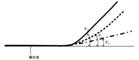
- FIG. 5 is an explanatory diagram of each angle relating to the recovery rate measurement.
- Elastic recovery rate [%] (1 ⁇ 1 / ⁇ 0 ) ⁇ 100
- Heat recovery rate [%] (1 ⁇ 2 / ⁇ 1 ) ⁇ 100
- Elasticity + Heat recovery rate [%] Average elastic recovery rate + (1 ⁇ 2 / ⁇ 1 ) ⁇ (1 ⁇ average elastic recovery rate) (Equation 3)
- FIG. 6 is a macroscopic observation result of the shape memory characteristics of the alloy foil of Experimental Example 1.
- FIG. 6A shows a homogenization process
- FIG. 6B shows a bending deformation
- FIG. 6C shows a heat recovery. It is a later photo.
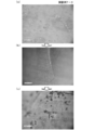
- 7 is an optical microscope observation result of the alloy foil of Experimental Example 1.
- FIG. 7A is a photograph after homogenization treatment
- FIG. 7B is a bending deformation
- FIG. 7C is a photograph after heat recovery. It is.
- FIG. 8 is an optical microscope observation result of the cast structure of Experimental Example 1.
- FIG. 9 is a crack photograph at the time of deformation in Experimental Example 1. As shown in FIG.
- FIG. 6 (b) when the experimental example 1 is bent and deformed, permanent strain remains, and as shown in FIG. 6 (c), when heat treatment is performed by heating at 700 ° C. (973K) for 1 minute, The shape recovered slightly.
- martensite was not confirmed (FIG. 7A), but stress-induced martensite was observed during deformation (FIG. 7B). Further, the stress-induced martensite disappeared after the heat treatment (FIG. 7C).
- FIG. 8 many bubbles having a diameter of 300 ⁇ m were confirmed even after the homogenization treatment (FIG. 8). Therefore, the sample piece was cracked from the bubble part at the time of bending deformation (FIG. 9).
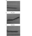
- FIG. 10 is a macroscopic observation result of the shape memory characteristics of the alloy foil of Experimental Example 2.
- FIG. 11 is an optical microscope observation result of the alloy foil of Experimental Example 2.
- FIG. 10 (b) when the experimental example 2 is bent and deformed, permanent strain remains, and as shown in FIG. 10 (c), when heat treatment is performed at 700 ° C. (973K) for 1 minute, Shape recovered. After the homogenization treatment, martensite was not confirmed (FIG. 11 (a)), but stress-induced martensite was observed during deformation (FIG. 11 (b)). Further, the stress-induced martensite was disappearing after the heat treatment (FIG. 11C).
- FIG. 12 is a relationship diagram between each temperature and elasticity + heating recovery rate in Experimental Example 2.
- FIG. 12 is a relationship diagram between each temperature and elasticity + heating recovery rate in Experimental Example 2.
- FIG. 13 is a relationship diagram between each temperature and the heat recovery rate in Experimental Example 2.
- Table 1 summarizes the measurement results of Experimental Example 2.
- the elastic recovery rate was 77%, and when the heat treatment was performed, the elastic recovery rate was greatly recovered at 500 ° C. (773 K) or more (FIG. 13), and the elasticity + heat recovery rate reached 95% (FIG. 12).
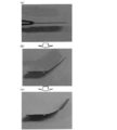
- FIG. 14 is a macroscopic observation result of the shape memory characteristics of the alloy foil of Experimental Example 3.
- FIG. 14 (a) is after homogenization processing
- FIG. 14 (b) is during bending deformation
- FIG. 14 (c) is heat recovery. It is a later photo.
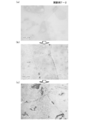
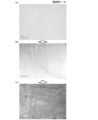
- FIG. 15 is a result of optical microscope observation of the alloy foil of Experimental Example 3.
- FIG. 15A is a photograph after homogenization treatment
- FIG. 15B is during bending deformation
- FIG. 15C is a photograph after heat recovery. It is. As shown in FIG.
- FIG. 14 (b) when the experimental example 3 is bent and deformed, permanent strain remains, and as shown in FIG. 14 (c), when heat treatment is performed by heating at 700 ° C. (973K) for 1 minute, Shape recovered. After the homogenization treatment, martensite was not confirmed (FIG. 15 (a)), but stress-induced martensite was observed during deformation (FIG. 15 (b)). Further, the stress-induced martensite disappeared after the heat treatment (FIG. 15 (c)).
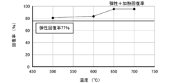
- FIG. 16 is a relationship diagram between each temperature and elasticity + heating recovery rate in Experimental Example 3.
- FIG. 17 is a relationship diagram between each temperature and the heat recovery rate in Experimental Example 3. Table 2 summarizes the measurement results of Experimental Example 3.
- FIG. 19 shows the XRD measurement results of Experimental Example 1.
- the constituent phase was ⁇ CuSn. That is, almost all phases were ⁇ CuSn. Further, this lattice constant was 2.99 ⁇ , which was slightly smaller than the literature value of 3.03 ⁇ .
- FIG. 20 shows the XRD measurement results of Experimental Example 2.
- the constituent phase was ⁇ CuSn. That is, almost all phases were ⁇ CuSn.
- the lattice constant of Experimental Example 2 was also 2.99 ⁇ , which was slightly smaller than the literature value of 3.03 ⁇ .
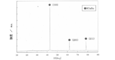
- FIG. 21 shows the XRD measurement results of Experimental Example 3.
- the constituent phase of Experimental Example 1 was ⁇ CuSn. It can be said that this sample shows a slight shape memory effect and stress-induced martensite develops. As described above, the reason why the shape memory effect of the sample is only slightly obtained is that there is a defect in casting, or because it contains many cast structures (bubbles) and breaks during bending deformation. Further, the reason why the lattice constant is smaller than the literature value will be considered with respect to the fact that the sample structure has a deviation compared to ⁇ CuSn (Cu 85 Sn 15 ).
- Cu 14 at% Sn ⁇ 2.5 at% Mn is ⁇ CuSn with a small amount of Sn and a large amount of Cu and Mn in solid solution.
- Cu and Mn have a smaller atomic radius than Sn. Therefore, it was thought that the reason why the lattice constant was small was that Cu and Mn having a smaller atomic radius than Sn were dissolved in ⁇ CuSn.
- the constituent phase of Experimental Example 2 was ⁇ CuSn. It can be said that this sample shows a shape memory effect and stress-induced martensite develops. Further, the reason why the lattice constant is smaller than the literature value will be considered with respect to the fact that the sample structure has a deviation compared to ⁇ CuSn (Cu 85 Sn 15 ).
- FIG. 22 shows a TEM observation result of Experimental Example 2.
- FIG. 23 shows TEM observation results of the parent phase of Experimental Example 2 when the tensile amount is changed.
- FIG. 23 (a) shows a tensile amount of 0 mm
- FIG. 23 (b) shows a tensile amount of 0.1 mm
- FIG. ) Is a tensile amount of 1.0 mm
- FIG. 23D is a tensile amount of 25 mm.
- FIG. 23 shows the result of tensile in-situ observation. Attention is paid to the central portion of the parent phase in FIG. As shown in FIG.
- FIG. 24 shows the TEM observation results of Experimental Example 3.
- Experimental Example 3 no extra wing-like diffraction spots were confirmed in the electron diffraction pattern.
- Experimental Example 2 no extra wing-like diffraction spots were observed in the electron diffraction pattern.
- stress-induced martensite was confirmed as in the optical microscope observation. This stress-induced martensite is considered to be a factor of the shape memory effect.
- the constituent phase of Experimental Example 2 was ⁇ CuSn.
- both the experimental examples 2 and 3 showed the shape memory effect.
- the average elastic recovery rate of the sample was about 80%. When heated, the sample recovered greatly at 500 ° C. (773 K) or higher, and the elasticity + heat recovery rate reached 90% or higher. Compared to Cu-14Sn, the elastic recovery increased from 35% to about 80%. It was thought that slip deformation due to dislocation was suppressed by addition of Mn, and elastic deformation was inhibited.
- the reason why the shape memory characteristic does not change due to room temperature aging is that Mn is a stabilizing element of ⁇ CuSn, and there is a possibility that the s phase and L phase that cause room temperature aging are not precipitated.
- the sample was vacuum sealed in a quartz tube to prevent oxidation. Further, after processing into sample shapes for various tests, an undercooling and high-temperature phase treatment was performed in order to obtain a single ⁇ -phase. Also in this case, in order to prevent oxidation, the sample was vacuum-sealed in a quartz tube, held in an electric furnace at each temperature for 30 minutes, and then each of the following methods (furnace cooling, water cooling, oil cooling, air cooling, -90 ° C methanol baking ).
- the cooling rates are 0.1 ° C./second for furnace cooling, 1 ° C./second for air cooling, 10 ° C./second for oil cooling, 100 ° C./second for water cooling, and about 100 ° C./second for methanol quenching at ⁇ 90 ° C. It is estimated to be.
- Some samples were then subjected to aging treatment. The aging treatment was performed under conditions of 10,000 minutes at room temperature after cooling with water, or conditions of 200 ° C. for 30 minutes after cooling with water.
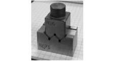
- FIG. 25 is a photograph of a bending test W block.
- a bent portion at the center of the W block was used.
- Elasticity + heat recovery rate [%] (1 ⁇ 2 / ⁇ 0 ) ⁇ 100 (Formula 4)
- the sample used for the optical microscope observation was the same as in the bending test.
- a digital microscope VH-8000 manufactured by Keyence was used for the optical microscope observation.
- the magnification of this device is 450-3000 times, but basically it was observed at 450 times.
- the molten alloy ingot was cut to a thickness of about 0.3 mm with a fine cutter and a micro cutter, and further mechanically polished to a thickness of 0.1 mm with a rotary polishing machine / water resistant polishing paper No. 100-800.
- the thin film sample was formed into a substantially square 3 mm square, heat-treated, and then electropolished under the following conditions.
- a dilute sulfuric acid (950 mL of distilled water, 50 mL of sulfuric acid, 2 g of sodium hydroxide, 15 g of iron (II) sulfate) was used as the electrolytic polishing liquid, and the sample was jet-polished at a liquid temperature of about 5 ° C. to 10 ° C.
- DTA Different thermal analysis
- the alloy ingot is cut into a cube with a width, length, and height of about 3 mm each using a fine cutter and a micro cutter, and mechanically polished by rotational polishing using No. 240 water-resistant abrasive paper to a mass of about 190 mg. It was.
- TG / DTA6200N and TG / DTA6300 manufactured by Seiko Instruments Inc. to measure temperature rise from room temperature to 700 ° C at 20 ° C / min, and then measure temperature drop from 700 ° C to room temperature at 20 ° C / min.
- a thermal analysis curve was obtained. During the measurement, nitrogen was flowed at a flow rate of 400 mL / min to prevent oxidation. Pure copper was used as a standard sample.
- Table 4 shows the compositions of Experimental Examples 4 to 8, the elastic recovery rate R E (%), the elastic heat recovery rate R E + T (%), and the crystal phase detected by XRD.
- Each experimental example is distinguished by assigning a subordinate number of 1 to 7 to samples of furnace cooling, air cooling, oil cooling, water cooling, quenching at ⁇ 90 ° C., water cooling and room temperature aging, and water cooling and 200 ° C. aging. That is, the air-cooled product of Experimental Example 7 is referred to as Experimental Example 7-2, and the water-cooled product of Experimental Example 7 is referred to as Experimental Example 7-4. As shown in Table 4, in Experimental Example 4-4 in which water cooling was performed without adding Mn, the elastic recovery rate was as low as 18%.
- the cooling rate for casting treatment, homogenization treatment, etc. is preferably oil cooling or higher, for example, a cooling rate greater than ⁇ 50 ° C./second.
- the amount of Mn added is too large, a secondary phase is precipitated, and therefore it is presumed that the range of 2.5 at% or more and 8.3 at% or less, more preferably 7.5 at% or less is preferable. .
- the measurement result of Experimental Example 7 is shown as a specific example of the copper alloy produced above.
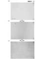
- 26 to 29 are optical microscope observation results of the alloy foils of Experimental Examples 7-2 to 5 (air cooling, oil cooling, water cooling, and ⁇ 90 ° C. cooling).
- (a) is a photograph after undercooling and high-temperature phase treatment
- (b) is during bending deformation
- (c) is a photograph after heat recovery.
- FIG. 30 shows the TEM observation result of Experimental Example 7.
- 31 to 34 are XRD measurement results of the copper alloys of Experimental Examples 7-2 to 4, 6 (air cooling, oil cooling, water cooling, water cooling and room temperature aging). As shown in FIG.
- FIG. 35 shows the DTA measurement results of Experimental Examples 4, 5, and 7.
- the temperature at which the ⁇ phase is phase-separated at the time of temperature increase increases as the concentration of Mn increases, and at the time of temperature decrease
- the temperature for eutectoid transformation of the ⁇ phase decreases as the concentration of Mn increases. It became clear that when the solid solution amount of Mn becomes larger, the temperature range in which the ⁇ CuSn phase stably exists, that is, the ⁇ CuSn phase becomes stable. From this, it was found that Mn can improve the thermal stability of the ⁇ CuSn phase, and it was speculated that the addition of Mn can prevent the change in characteristics due to room temperature aging.
- the invention disclosed in this specification can be used in fields related to copper alloys.
Landscapes
- Chemical & Material Sciences (AREA)
- Engineering & Computer Science (AREA)
- Materials Engineering (AREA)
- Mechanical Engineering (AREA)
- Metallurgy (AREA)
- Organic Chemistry (AREA)
- Physics & Mathematics (AREA)
- Thermal Sciences (AREA)
- Crystallography & Structural Chemistry (AREA)
- Conductive Materials (AREA)
- Heat Treatment Of Sheet Steel (AREA)
Abstract
Description
基本合金組成がCu100-(x+y)SnxMny(但し8≦x≦16、2≦y≦10を満たす)であり、Mnが固溶したβCuSn相を主相とし、該βCuSn相が熱処理あるいは加工によりマルテンサイト変態するものである。
熱処理あるいは加工によりマルテンサイト変態する銅合金の製造方法であって、
CuとSnとMnとを含み基本合金組成がCu100-(x+y)SnxMny(但し8≦x≦16、2≦y≦10を満たす)となる原料を溶解鋳造し鋳造材を得る鋳造工程と、
前記鋳造材をβCuSn相の温度域内で均質化処理し均質化材を得る均質化工程と、のうち少なくとも前記鋳造工程を含むものである。
本明細書で開示する銅合金は、基本合金組成がCu100-(x+y)SnxMny(但し8≦x≦16、2≦y≦10を満たす)であり、Mnが固溶したβCuSn相を主相とし、該βCuSn相が熱処理あるいは加工によりマルテンサイト変態するものである。ここで、主相とは、全体に占める中で最も多く含まれる相をいい、例えば、50質量%以上含まれる相としてもよく、80質量%以上含まれる相としてもよいし、90質量%以上含まれる相としてもよい。この銅合金では、βCuSn相が95質量%以上、より好ましくは、98質量%以上含まれている。この銅合金は、500℃以上の温度で処理したのち冷却したものであり、融点以下の温度で形状記憶効果及び超弾性効果のうち1以上を有するものとしてもよい。この銅合金では、主相がβCuSn相であるため、形状記憶効果や超弾性効果を発現することができる。あるいは、この銅合金は、表面観察において、βCuSn相が面積比で50%以上100%以下の範囲で含まれるものとしてもよい。このように表面観察により主相を求めるものとしてもよい。このβCuSn相の面積比は、95%以上、より好ましくは、98%以上であるものとしてもよい。この銅合金は、βCuSn相を単相として含むことが最も好ましいが、他の相が含まれてもよい。
弾性回復率RE[%]=(1-θ1/θ0)×100 …(数式1)
加熱回復率RT[%]=(1-θ2/θ1)×100 …(数式2)
弾性加熱回復率RE+T[%]
= 平均弾性回復率+(1-θ2/θ1)×(1-平均弾性回復率)…(数式3)
この製造方法は、熱処理あるいは加工によりマルテンサイト変態する銅合金の製造方法であって、鋳造工程と、均質化工程とのうち少なくとも鋳造工程を含むものである。
鋳造工程では、CuとSnとMnとを含み基本合金組成がCu100-(x+y)SnxMny(但し8≦x≦16、2≦y≦10を満たす)となる原料を溶解鋳造し鋳造材を得る。このとき、原料を溶解鋳造しβCuSn相を主相とする鋳造材を得るものとしてもよい。Cu、Sn、Mnの原料としては、例えば、これらの単体やこれらのうちの2種以上を含む合金を用いることができる。また、原料の配合比は、所望の基本合金組成に合わせて調整すればよい。この工程では、CuSn相にMnを固溶させるため、溶融順序はCu、Mn、Snの順に原料を加えて鋳造することが好ましい。溶解方法は、特に限定されないが、高周波溶解法が効率よく、工業的利用が可能であり好ましい。鋳造工程では、窒素、Ar、真空中など不活性雰囲気下で行うことが好ましい。鋳造体の酸化をより抑制することができる。この工程では、750℃以上1300℃以下の温度範囲で原料を溶解し、800℃~400℃の間を-50℃/s~-500℃/sの冷却速度で冷却することが好ましい。冷却速度は、できるだけ大きい方が安定的なβCuSn相を得るのに好ましい。冷却方法としては、空冷、油冷、水冷などが挙げられ、水冷が好ましい。
均質化工程では、鋳造材をβCuSn相の温度域内で均質化処理し均質化材を得る。この工程では、600℃以上850℃以下の温度範囲で鋳造材を保持したのち、-50℃/s~-500℃/sの冷却速度で冷却することが好ましい。冷却速度は、できるだけ大きい方が安定的なβCuSn相を得るのに好ましい。均質化温度は、例えば、650℃以上がより好ましく、700℃以上が更に好ましい。また、均質化温度は、800℃以下がより好ましく、750℃以下が更に好ましい。均質化時間は、例えば、20分以上としてもよいし30分以上としてもよい。また、均質化時間は、例えば、48時間以下としてもよいし24時間以下としてもよい。均質化処理においても、窒素、Ar、真空中など不活性雰囲気下で行うことが好ましい。
鋳造工程及び均質化工程のいずれかのあとに他の工程を行ってもよい。例えば、銅合金の製造方法は、鋳造材及び均質化材のうち1以上に対して、板状、箔状、棒状、線状及び所定形状のうちいずれか1以上に冷間加工又は熱間加工する1以上の加工工程、を更に含むものとしてもよい。この加工工程では、500℃以上700℃以下の温度範囲で熱間加工を行い、その後-50℃/s~-500℃/sの冷却速度で冷却するものとしてもよい。また、加工工程では、せん断変形の発生を抑制する方法により、断面減少率が50%以下で加工するものとしてもよい。あるいは、銅合金の製造方法は、鋳造材及び均質化材のうち1以上に対して、時効硬化処理を行い時効硬化材を得る時効化工程を更に含むものとしてもよい。あるいは、銅合金の製造方法は、鋳造材及び均質化材のうち1以上に対して、規則化処理を行い規則化材を得る規則化工程を更に含むものとしてもよい。この工程では、100℃以上400℃以下の温度範囲、0.5h以上24h以下の時間範囲で時効硬化処理または規則化処理を行うものとしてもよい。
Cu-Sn-Mn系合金を作製した。Cu-Sn二元系状態図(図1)を参照して、対象試料の高温での構成相がβCuSn単相となる組成を目標組成とした。参考とした状態図はASM International DESK HANDBOOK Phase Diagrams for Binary Alloys Second Edition(5)とASM International Handbook of Ternary Alloy Phase Diagramsによる実験的状態図である。またCALPHAD法により平衡状態図を作成するソフトであるThermo-Calcによる計算的状態図も使用した。図2~4は、Mn=2.5at%、5.0at%、8.3at%でのCuSnMn合金の計算的状態図である。溶製された合金が、目標組成付近となるように純Cu、純Sn、純Mnを秤量し、大気用高周波溶解炉でN2ガスを噴きかけながら溶融・鋳造して合金試料を作製した。目標組成は、Cu100-(x+y)SnxMny(x=14,13、y=2.5,4.9)とし、溶融順序は、Cu→Mn→Snとした。溶製された鋳造試料はそのままであると凝固組織が残って不均一であるため、均質化処理を施した。その際、酸化防止を図るために試料は石英管に真空封入し、マッフル炉で700℃(973K)、30分保持したのち、氷水中に入れて急冷すると同時に石英管を破壊した。基本合金組成でx=14、y=2.5のものを実験例1とし、x=13、y=4.9を実験例2とした。
合金鋳塊をファインカッタとマイクロカッタを用いて厚さ0.2~0.3mmに切り出し、100~2000番の耐水研摩紙を貼り付けた回転研摩機で機械研磨し、アルミナ液(アルミナ径0.3μm)でバフ研摩を行い、鏡面を得た。光学顕微鏡観察試料は曲げ試験試料としても扱うため、試料厚さもそろえてから熱処理(均質化処理)を施した。試料厚さは0.15mmとした。光学顕微鏡観察には、キーエンス製デジタルマイクロスコープVH-8000を用いた。本装置の拡大可能倍率は450~3000倍であるが、基本的に450倍で観察した。
XRD測定試料は、以下のように作製した。合金鋳塊をファインカッタで切り出し、端部を金やすりで削って粉末試料を得た。熱処理を施した後、XRD測定試料とした。焼き入れ時は通常試料のように石英管を水中で破砕すると粉末試料が水分を含んでしまうことと酸化の危険性があるため、冷却時に石英管は破壊していない。XRD測定装置は、リガク製RINT2500を用いた。この回折装置は、回転対陰極型X線回折装置で、対陰極であるロータターゲット:Cu、管電圧:40kV、管電流:200mA、測定範囲:10~120°、サンプリング幅:0.02°、測定速度:2°/分、発散スリット角度:1°、散乱スリット角度:1°、受光スリット幅:0.3mmで測定した。データ解析は、統合粉末X線解析ソフトウェアRIGAKU PDXLを用いて出現ピークを解析し、相同定・相分率の算出を行った。なお、PDXLはピーク同定にHanawalt法を採用している。
TEM観察試料は、以下のように作製した。溶製した合金鋳塊をファインカッタとマイクロカッタで厚さ0.2~0.3mmに切り出し、さらに回転研磨機・耐水研磨紙2000番で厚さ0.15~0.25mmまで機械研磨した。この薄膜試料を3mm四方に成形し、熱処理を施した後、以下の条件で電解研磨した。電解研磨では、電解研磨液としてナイタールを用い、約-20℃~-10℃(253~263K)に温度保持した状態でジェット研磨した。使用した電解研磨装置は、STRUERS社製テヌポールであり、以下の条件で研磨した。研磨条件は、電圧:5~10V、電流:0.5A、流量:2.5とし、研磨開始から30秒は酸化皮膜形成、研磨終了までは酸化皮膜を除去するものとし、二段階で電解研磨した。試料は電解研磨後、直ちに観察した。TEM観察は、日立H-800(サイドエントリ分析仕様)TEM(加速電圧175kV)を用いた。また、一軸引張ホルダを用いたその場TEM観察も行った。引張その場観察にはH-800付属装置であるH-5001T型試料引張ホルダを用いた。加熱その場観察にはH-800付属装置である加熱ホルダを用いた。
合金鋳塊をファインカッタとマイクロカッタを用いて厚さ0.3mmに切り出し、100~2000番の耐水研摩紙を用いて回転研摩によって機械研磨し、厚さ0.15mmとした。なお、Cu-Sn-Mnは、厚さ0.1mmでは弾性的に回復してしまい、曲げ変形時にマルテンサイトも観察されないため、厚さを0.15mmとした。上記光学顕微鏡観察の試料と同様の処理を施し、熱処理後の試料をR=0.75mmのガイドに巻き付けて90°の曲げ角で押し曲げることによって曲げ変形を加えた。なお、Cu-Sn-Mnは、45°曲げでは弾性的に回復してしまい、曲げ変形時にマルテンサイトも観察されないため、90°曲げとした。試料の曲げ角度θ0(90°)、除荷後の角度θ1、750℃(1023K)で1分、加熱処理した後の角度θ2を測定し、弾性回復率と加熱回復率を以下の式によって求めた。また、変形後に加熱温度を変えることで回復率-温度曲線も得た。回復率-温度曲線を求める際、曲げ時に加える応力を各試料で一定にはできないため、試料ごとに除荷時の角度(弾性回復率)に差が生じやすい。そのため、弾性+加熱回復率は、弾性回復率の平均値を求め、加熱回復率を補正して以下の式によって求めた。図5は、回復率測定に関する各角度の説明図である。
弾性回復率[%]=(1-θ1/θ0)×100 …(数式1)
加熱回復率[%]=(1-θ2/θ1)×100 …(数式2)
弾性+加熱回復率[%]
= 平均弾性回復率+(1-θ2/θ1)×(1-平均弾性回復率)…(数式3)

実験例2を室温で10000分時効した銅合金を実験例3とした。実験例3に対しても、実験例1と同様の測定を行った。図14は、実験例3の合金箔の形状記憶特性の巨視観察結果であり、図14(a)が均質化処理後、図14(b)が曲げ変形時、図14(c)が加熱回復後の写真である。図15は、実験例3の合金箔の光学顕微鏡観察結果であり、図15(a)が均質化処理後、図15(b)が曲げ変形時、図15(c)が加熱回復後の写真である。図14(b)に示すように、実験例3を曲げ変形させると、永久歪みが残り、図14(c)に示すように、700℃(973K)で1分加熱する加熱処理を行うと、形状回復した。均質化処理後は、マルテンサイトが確認されなかったが(図15(a))、変形時に応力誘起マルテンサイトが観察された(図15(b))。また、加熱処理後に応力誘起マルテンサイトは消滅した(図15(c))。図16は、実験例3の各温度と弾性+加熱回復率との関係図である。図17は、実験例3の各温度と加熱回復率との関係図である。表2には、実験例3の測定結果をまとめた。実験例3では、弾性回復率は、80%であり、加熱処理すると500℃(773K)以上で大きく回復し(図17)、弾性+加熱回復率は93%に達した(図16)。図14、15に示すように、実験例3においても、弾性回復し、且つ加熱処理すると大きく回復した。即ち、常温で時効した場合でも、形状記憶特性は、維持されていることがわかった。

実験例1では、形状記憶効果を示し、均質化処理後にはマルテンサイトが確認されなかったが、変形時に応力誘起マルテンサイトが観察された。また、加熱処理後にはマルテンサイトは消滅したことから、この形状記憶効果は応力誘起マルテンサイトによるものと思われる。しかし、この試料は均質化処理後も図8のような直径300μmの気泡が多数確認された。そのため、曲げ変形時に試料片がその気泡の部分から割れてしまった。この気泡は鋳造組織であり、鋳造組織の残存は溶解・鋳造がうまくいかなかったためである。そのため、作製したこの鋳塊では、形状回復率の正確な測定が困難であった。実験例2では、形状記憶効果を示し、均質化処理後にはマルテンサイトが確認されなかったが、変形時に応力誘起マルテンサイトが観察された。また、加熱処理後にはマルテンサイトは消滅しかけていた。これより、この形状記憶効果は応力誘起マルテンサイトによるものと思われる。試料の平均弾性回復率は、77%で、加熱すると500℃(773K)以上で大きく回復し、弾性+加熱回復率は、95%に達した。Cu-14at%Snに比して、弾性回復率が35%から77%へと上昇した。Mn添加により、転位によるすべり変形が抑制され、塑性変形が阻害されたのではないかと思われた。実験例3では、室温時効後も形状記憶効果を示し、均質化処理後はマルテンサイトが確認されなかったが、変形時に応力誘起マルテンサイトが観察された。また、加熱処理後に応力誘起マルテンサイトは消滅したことにより、この形状記憶効果が応力誘起マルテンサイトによるものと思われた。試料の平均弾性回復率は、80%で、加熱すると500℃(773K)以上で大きく回復し、弾性+加熱回復率は、93%に達した。Cu-14at%Snに比して、弾性回復率が35%から80%へと上昇した。Mn添加により、転位によるすべり変形が抑制され、塑性変形が阻害されたのではないかと思われた。
Cu-Sn-Mn系合金を作製し、更に形状記憶特性について検討した。表3に実験例4~8のCu-Sn-Mn系合金の組成をまとめて示した。目標組成付近となるように原料である純Cu、純Sn、純Mnを秤量し、大気用高周波溶解炉でN2ガスまたはArガスを噴きかけながら溶融・金型鋳造をすることで試料を作製した。実験例5,6はN2ガス、実験例4、7、8はArガスを用いて溶解鋳造した。溶製された鋳造組織は、そのままであると凝固組織が残って不均一であるため、電気炉において700℃、24hの均質化処理を施した。その際、酸化防止のために試料を石英管内に真空封入した。さらに種々の試験の試料形状に加工した後、β相単相化するために過冷高温相化処理を施した。この際も酸化防止のために試料を石英管内に真空封入し、電気炉でそれぞれの温度で30分保持した後、それぞれ以下の方法(炉冷、水冷、油冷、空冷、-90℃メタノール焼き入れ)で冷却した。それぞれの冷却速度は、炉冷が0.1℃/秒、空冷が1℃/秒、油冷が10℃/秒、水冷が100℃/秒、-90℃メタノール焼き入れが100℃/秒程度と推定される。試料によってはその後、時効処理を施した。時効処理は、水冷後に室温で10000分の条件か、水冷後に200℃、30分間の条件で行った。

合金鋳塊をファインカッタとマイクロカッタを用いて厚さ約0.3mmに切り出し、100~2000番の耐水研摩紙を用いて回転研摩によって機械研磨し、厚さ0.15mmとした。曲げ試験試料は光学顕微鏡観察試料としても扱うため、アルミナ液(0.3μm)を用い、バフ研摩して鏡面を得てから、過冷高温相化処理を施した。熱処理後に希王水(蒸留水:塩酸:硝酸=8:1:1)によって化学エッチングを行った。熱処理を施した試料をR=0.75mm、曲げ角90°のW型ブロックをガイドとして用いて、押し曲げることによって曲げ変形を加えた。図25は、曲げ試験用Wブロックの写真である。試料の曲げ角度θ0(=90°)、除荷後の角度θ1、700℃で1分加熱処理した後の角度θ2を測定し、弾性回復率と弾性+加熱回復率を上記数式(1)及び数式(4)によって求めた。測定にはWブロック中央部による曲がり部分を用いた。
弾性+加熱回復率[%]=(1-θ2/θ0)×100 …(数式4)
光学顕微鏡観察に用いる試料は、曲げ試験と同等のものを用いた。光学顕微鏡観察は、キーエンス製デジタルマイクロスコープVH-8000を用いた。本装置の拡大可能倍率は450~3000倍だが、基本的に450倍で観察した。
測定試料、測定装置、測定条件及び解析方法は、上述した実験例1と同様とした。
溶製した合金鋳塊をファインカッタとマイクロカッタで厚さ約0.3mmに切り出し、さらに回転研磨機・耐水研磨紙100~800番で厚さ0.1mmまで機械研磨した。この薄膜試料を3mm四方のほぼ正方形に成形し、熱処理を施した後、以下の条件で電解研磨した。電解研磨液として希硫酸(蒸留水950mL、硫酸50mL、水酸化ナトリウム2g、硫酸鉄(II)15g)を用い、液温約5℃~10℃で試料をジェット研磨した。ジェット電解研磨装置は、STRUERS社製テヌポールIII、Vを使用した。試料は、電解研磨後、直ちにTEM観察した。TEM観察は、日立H-800(サイドエントリ分析仕様)TEM(加速電圧175kV)を用いた。観察の際、結晶方位を100あるいは110晶帯からの入射になるように2軸試料傾斜機構を用いて調整した。露光時間は多くの場合約3秒前後である。多くの場合、観察は対物絞りを透過波に入れた明視野像である。
合金鋳塊をファインカッタとマイクロカッタを用いて幅と長さと高さがそれぞれ約3mmの立方体になるように切り出し、240番の耐水研摩紙を用いて回転研摩によって機械研磨し、質量を約190mgとした。DTA測定は、セイコーインスツルメント製TG/DTA6200NとTG/DTA6300を用いて、室温から700℃まで20℃/分で昇温測定し、その後700℃から室温まで20℃/分で降温測定することで熱分析曲線を得た。測定中は酸化防止のため、窒素を流量400mL/分で流した。標準試料には純銅を用いた。
実験例4~8の組成、弾性回復率RE(%)、弾性加熱回復率RE+T(%)、及びXRDで検出された結晶相をまとめて表4に示す。各実験例は、炉冷、空冷、油冷、水冷、-90℃焼き入れ、水冷後室温時効、水冷後200℃時効の試料に対してそれぞれ1~7の下位番号を付けて区別する。即ち、実験例7の空冷品は実験例7-2、実験例7の水冷品は実験例7-4と称する。表4に示すように、Mnを添加せず水冷した実験例4-4では、弾性回復率が18%と低かった。また、水冷後、室温時効した実験例4-6では、弾性回復率が61%と大きく変化した。これに対して、Mnを添加した実験例5~6では、主相がβCuSn相であり、40%以上の弾性回復率を示し、高い形状記憶特性を示した。また、実験例6~8では、室温時効した前後で、回復率の大きな変化はみられず、結晶の安定性が高いことがわかった。実験例7では、空冷程度の冷却速度でも比較的高い形状記憶特性を示した。また、400℃以上に加熱したのち冷却する際に、この冷却速度が小さいと、α相やδ相、金属間化合物(Cu4MnSnなど)などが析出して単相になりにくくなり、脆くなって加工が難しくなった。これらの結果より、鋳造処理、均質化処理などの冷却速度は、油冷以上、例えば-50℃/秒よりも大きな冷却速度であることが好ましいと推察された。また、Mnの添加量は、多すぎると副相が析出することから、2.5at%以上8.3at%以下の範囲、より好ましくは7.5at%以下の範囲が良好であると推察された。

Claims (16)
- 基本合金組成がCu100-(x+y)SnxMny(但し8≦x≦16、2≦y≦10を満たす)であり、Mnが固溶したβCuSn相を主相とし、該βCuSn相が熱処理あるいは加工によりマルテンサイト変態する、銅合金。
- 融点以下の温度で形状記憶効果及び超弾性効果のうち1以上を有する、請求項1に記載の銅合金。
- 平板状の前記銅合金を曲げ角度θ0で曲げたのち、除荷したときの角度θにより求められる弾性回復率(%)が40%以上である、請求項1又は2に記載の銅合金。
- 平板状の前記銅合金を曲げ角度θ0で曲げたのち、βCuSn相に基づいて定められる所定の回復温度に加熱したときの角度θにより求められる加熱回復率(%)が40%以上である、請求項1~3のいずれか1項に記載の銅合金。
- 平板状の前記銅合金を曲げ角度θ0で曲げたのち除荷したときの角度θ1、更にβCuSn相に基づいて定められる所定の回復温度に加熱したときの角度θ2より求められる弾性加熱回復率(%)が45%以上である、請求項1~4のいずれか1項に記載の銅合金。
- 表面観察において、前記βCuSn相が面積比で50%以上100%以下の範囲で含まれる、請求項1~5のいずれか1項に記載の銅合金。
- 多結晶又は単結晶からなる、請求項1~6のいずれか1項に記載の銅合金。
- 鋳造材が均質化された均質化材である、請求項1~7のいずれか1項に記載の銅合金。
- 熱処理あるいは加工によりマルテンサイト変態する銅合金の製造方法であって、
CuとSnとMnとを含み基本合金組成がCu100-(x+y)SnxMny(但し8≦x≦16、2≦y≦10を満たす)となる原料を溶解鋳造し鋳造材を得る鋳造工程と、
前記鋳造材をβCuSn相の温度域内で均質化処理し均質化材を得る均質化工程と、のうち少なくとも前記鋳造工程を含む、銅合金の製造方法。 - 前記鋳造工程では、750℃以上1300℃以下の温度範囲で前記原料を溶解し、800℃~400℃の間を-50℃/s~-500℃/sの冷却速度で冷却する、請求項9に記載の銅合金の製造方法。
- 前記均質化工程では、600℃以上850℃以下の温度範囲で保持したのち-50℃/s~-500℃/sの冷却速度で冷却する、請求項9又は10に記載の銅合金の製造方法。
- 請求項9~11のいずれか1項に記載の銅合金の製造方法であって、
前記鋳造材及び前記均質化材のうち1以上に対して、板状、箔状、棒状、線状及び所定形状のうちいずれか1以上に冷間加工又は熱間加工する1以上の加工工程、を更に含む、銅合金の製造方法。 - 前記加工工程では、500℃以上700℃以下の温度範囲で熱間加工を行い、その後-50℃/s~-500℃/sの冷却速度で冷却する、請求項12に記載の銅合金の製造方法。
- 前記加工工程では、せん断変形の発生を抑制する方法により、断面減少率が50%以下で加工する、請求項12又は13に記載の銅合金の製造方法。
- 請求項9~14のいずれか1項に記載の銅合金の製造方法であって、
前記鋳造材及び前記均質化材のうち1以上に対して、時効硬化処理または規則化処理を行い時効硬化材または規則化材を得る時効または規則化工程、を更に含む、銅合金の製造方法。 - 前記時効工程では、100℃以上400℃以下の温度範囲、0.5h以上24h以下の時間範囲で前記時効硬化処理または規則化処理を行う、請求項15に記載の銅合金の製造方法。
Priority Applications (5)
| Application Number | Priority Date | Filing Date | Title |
|---|---|---|---|
| EP17770435.0A EP3441487B1 (en) | 2016-03-25 | 2017-03-24 | Copper alloy and method for producing same |
| JP2018507456A JP6832547B2 (ja) | 2016-03-25 | 2017-03-24 | 銅合金及びその製造方法 |
| CN201780019318.6A CN108779515B (zh) | 2016-03-25 | 2017-03-24 | 铜合金及其制造方法 |
| KR1020187027621A KR102215220B1 (ko) | 2016-03-25 | 2017-03-24 | 구리 합금 및 그 제조 방법 |
| US16/136,684 US10774401B2 (en) | 2016-03-25 | 2018-09-20 | Copper alloy and method for producing same |
Applications Claiming Priority (2)
| Application Number | Priority Date | Filing Date | Title |
|---|---|---|---|
| US201662313228P | 2016-03-25 | 2016-03-25 | |
| US62/313,228 | 2016-03-25 |
Related Child Applications (1)
| Application Number | Title | Priority Date | Filing Date |
|---|---|---|---|
| US16/136,684 Continuation US10774401B2 (en) | 2016-03-25 | 2018-09-20 | Copper alloy and method for producing same |
Publications (1)
| Publication Number | Publication Date |
|---|---|
| WO2017164395A1 true WO2017164395A1 (ja) | 2017-09-28 |
Family
ID=59899601
Family Applications (2)
| Application Number | Title | Priority Date | Filing Date |
|---|---|---|---|
| PCT/JP2017/012129 Ceased WO2017164396A1 (ja) | 2016-03-25 | 2017-03-24 | 銅合金及びその製造方法 |
| PCT/JP2017/012128 Ceased WO2017164395A1 (ja) | 2016-03-25 | 2017-03-24 | 銅合金及びその製造方法 |
Family Applications Before (1)
| Application Number | Title | Priority Date | Filing Date |
|---|---|---|---|
| PCT/JP2017/012129 Ceased WO2017164396A1 (ja) | 2016-03-25 | 2017-03-24 | 銅合金及びその製造方法 |
Country Status (6)
| Country | Link |
|---|---|
| US (2) | US10954586B2 (ja) |
| EP (2) | EP3318648B1 (ja) |
| JP (2) | JP6832547B2 (ja) |
| KR (2) | KR102364117B1 (ja) |
| CN (2) | CN107923000B (ja) |
| WO (2) | WO2017164396A1 (ja) |
Cited By (1)
| Publication number | Priority date | Publication date | Assignee | Title |
|---|---|---|---|---|
| JP2019167573A (ja) * | 2018-03-22 | 2019-10-03 | 国立大学法人横浜国立大学 | Cu−Sn−Si系超弾性合金及びその製造方法 |
Families Citing this family (5)
| Publication number | Priority date | Publication date | Assignee | Title |
|---|---|---|---|---|
| CN107923000B (zh) * | 2016-03-25 | 2021-02-12 | 日本碍子株式会社 | 铜合金及其制造方法 |
| CN111172442B (zh) * | 2020-01-09 | 2021-05-25 | 西安建筑科技大学 | 一种3d打印的稀土镁合金粉体及其制备方法 |
| CN111304487B (zh) * | 2020-03-24 | 2021-05-25 | 安新县华昌合金厂 | 一种铜基形状记忆合金及其制备方法和应用 |
| CN111521622B (zh) * | 2020-04-10 | 2022-04-19 | 燕山大学 | 一种采用金属薄膜透射电镜样品研究其氧化过程的方法 |
| CN119464831A (zh) * | 2025-01-16 | 2025-02-18 | 国工恒昌新材料(义乌)有限公司 | 一种耐高温锰铜合金材料的制备方法 |
Citations (2)
| Publication number | Priority date | Publication date | Assignee | Title |
|---|---|---|---|---|
| JP2004263298A (ja) * | 2003-02-28 | 2004-09-24 | Wieland Werke Ag | 無鉛銅合金およびその使用方法 |
| WO2014034104A1 (ja) * | 2012-08-27 | 2014-03-06 | 新日鐵住金株式会社 | 負極活物質材料 |
Family Cites Families (13)
| Publication number | Priority date | Publication date | Assignee | Title |
|---|---|---|---|---|
| US484073A (en) * | 1892-10-11 | Egbert weigel and bruno waechtler | ||
| NL7002632A (ja) * | 1970-02-25 | 1971-08-27 | ||
| SU484073A1 (ru) * | 1973-12-11 | 1975-09-15 | Предприятие П/Я Р-6205 | Металлическа св зка мв 5-10 |
| US4036669A (en) * | 1975-02-18 | 1977-07-19 | Raychem Corporation | Mechanical preconditioning method |
| GB8305610D0 (en) * | 1983-03-01 | 1983-03-30 | Imi Kynoch Ltd | Alloy |
| JPH109294A (ja) * | 1996-06-19 | 1998-01-13 | Sumitomo Electric Ind Ltd | 二輪車用ローラーブレーキとその製造方法 |
| JP3761741B2 (ja) * | 1999-05-07 | 2006-03-29 | 株式会社キッツ | 黄銅とこの黄銅製品 |
| JP3300684B2 (ja) * | 1999-07-08 | 2002-07-08 | 清仁 石田 | 形状記憶特性及び超弾性を有する銅系合金、それからなる部材ならびにそれらの製造方法 |
| JP4424810B2 (ja) * | 2000-03-27 | 2010-03-03 | 株式会社小松製作所 | 焼結材料 |
| KR20140102846A (ko) * | 2013-02-15 | 2014-08-25 | 한국산업기술대학교산학협력단 | 냉간 가공성이 우수한 형상 기억 합금 |
| KR102162393B1 (ko) * | 2014-02-25 | 2020-10-06 | 닛폰세이테츠 가부시키가이샤 | 음극 활물질 재료, 음극 및 전지 |
| CN105369043B (zh) * | 2015-10-23 | 2017-08-08 | 北京科技大学 | 高超弹性高马氏体相变临界应力形状记忆合金及制备方法 |
| CN107923000B (zh) * | 2016-03-25 | 2021-02-12 | 日本碍子株式会社 | 铜合金及其制造方法 |
-
2017
- 2017-03-24 CN CN201780002584.8A patent/CN107923000B/zh not_active Expired - Fee Related
- 2017-03-24 EP EP17770436.8A patent/EP3318648B1/en active Active
- 2017-03-24 JP JP2018507456A patent/JP6832547B2/ja not_active Expired - Fee Related
- 2017-03-24 CN CN201780019318.6A patent/CN108779515B/zh not_active Expired - Fee Related
- 2017-03-24 KR KR1020187027620A patent/KR102364117B1/ko not_active Expired - Fee Related
- 2017-03-24 WO PCT/JP2017/012129 patent/WO2017164396A1/ja not_active Ceased
- 2017-03-24 EP EP17770435.0A patent/EP3441487B1/en not_active Not-in-force
- 2017-03-24 KR KR1020187027621A patent/KR102215220B1/ko not_active Expired - Fee Related
- 2017-03-24 JP JP2017545975A patent/JP6358609B2/ja not_active Expired - Fee Related
- 2017-03-24 WO PCT/JP2017/012128 patent/WO2017164395A1/ja not_active Ceased
-
2018
- 2018-02-22 US US15/902,230 patent/US10954586B2/en not_active Expired - Fee Related
- 2018-09-20 US US16/136,684 patent/US10774401B2/en active Active
Patent Citations (2)
| Publication number | Priority date | Publication date | Assignee | Title |
|---|---|---|---|---|
| JP2004263298A (ja) * | 2003-02-28 | 2004-09-24 | Wieland Werke Ag | 無鉛銅合金およびその使用方法 |
| WO2014034104A1 (ja) * | 2012-08-27 | 2014-03-06 | 新日鐵住金株式会社 | 負極活物質材料 |
Non-Patent Citations (5)
| Title |
|---|
| DASGUPTA RUPA ET AL.: "A look into Cu-based shape memory alloys:Present scenario and future prospects", J.MATER.RES., vol. 29, no. 16, 28 August 2014 (2014-08-28), pages 1681 - 1698, XP055550793 * |
| JOURNAL OF TEXTILE ENGINEERING, vol. 42, 1989, pages 587 |
| JOURNAL OF THE JAPAN INSTITUTE OF METALS AND MATERIALS, vol. 19, 1980, pages 323 |
| LIU X.J. ET AL.: "Experimental Investigation and Thermodynamic Calculation of the Phase Equilibria in the Cu-Sn and Cu-Sn-Mn Systems", METALLURGICAL AND MATERIALS TRANSACTIONS A, vol. 35A, no. 6, June 2004 (2004-06-01), pages 1641 - 1654, XP019694973 * |
| PRASHANTHA.S ET AL.: "SHAPE MEMORY EFFECT IN Cu- Sn-Mn TERNARY SHAPE MEMORY ALLOY PROCESSED BY INGOT METALLURGY", INT. J. METALL. MATER. SCI. ENG.(IJMMSE, vol. 2, no. 1, March 2012 (2012-03-01), pages 12 - 20, XP055550774 * |
Cited By (1)
| Publication number | Priority date | Publication date | Assignee | Title |
|---|---|---|---|---|
| JP2019167573A (ja) * | 2018-03-22 | 2019-10-03 | 国立大学法人横浜国立大学 | Cu−Sn−Si系超弾性合金及びその製造方法 |
Also Published As
| Publication number | Publication date |
|---|---|
| EP3318648B1 (en) | 2020-02-19 |
| KR102364117B1 (ko) | 2022-02-18 |
| CN108779515A (zh) | 2018-11-09 |
| JP6832547B2 (ja) | 2021-02-24 |
| EP3441487A4 (en) | 2019-10-23 |
| US20190017148A1 (en) | 2019-01-17 |
| WO2017164396A1 (ja) | 2017-09-28 |
| EP3441487A1 (en) | 2019-02-13 |
| US10774401B2 (en) | 2020-09-15 |
| KR102215220B1 (ko) | 2021-02-16 |
| US10954586B2 (en) | 2021-03-23 |
| CN107923000A (zh) | 2018-04-17 |
| JP6358609B2 (ja) | 2018-07-18 |
| CN107923000B (zh) | 2021-02-12 |
| KR20180119615A (ko) | 2018-11-02 |
| EP3318648A4 (en) | 2019-05-08 |
| JPWO2017164396A1 (ja) | 2018-03-29 |
| KR20180125484A (ko) | 2018-11-23 |
| EP3318648A1 (en) | 2018-05-09 |
| US20180209025A1 (en) | 2018-07-26 |
| CN108779515B (zh) | 2020-12-22 |
| JPWO2017164395A1 (ja) | 2019-02-14 |
| EP3441487B1 (en) | 2021-03-03 |
Similar Documents
| Publication | Publication Date | Title |
|---|---|---|
| WO2017164395A1 (ja) | 銅合金及びその製造方法 | |
| JP5962707B2 (ja) | 電子・電気機器用銅合金、電子・電気機器用銅合金塑性加工材、電子・電気機器用銅合金塑性加工材の製造方法、電子・電気機器用部品及び端子 | |
| CN107208189B (zh) | 铜合金、铜合金塑性加工材、组件、端子及汇流条 | |
| CN105992831B (zh) | 电子电气设备用铜合金、电子电气设备用铜合金塑性加工材、电子电气设备用部件及端子 | |
| CN103842531A (zh) | 电子设备用铜合金、电子设备用铜合金的制造方法、电子设备用铜合金塑性加工材料及电子设备用组件 | |
| CN107614714B (zh) | 电子电气设备用铜合金板、电子电气设备用铜合金塑性加工材、电子电气设备用组件、端子及汇流条 | |
| TW201313924A (zh) | 電子機器用銅合金、電子機器用銅合金之製造方法、電子機器銅合金用塑性加工材、以及電子機器用零件 | |
| JP5834528B2 (ja) | 電気・電子機器用銅合金 | |
| JP6187629B1 (ja) | 電子・電気機器用銅合金、電子・電気機器用銅合金塑性加工材、電子・電気機器用部品、端子、及び、バスバー | |
| WO2021060013A1 (ja) | 電子・電気機器用銅合金、電子・電気機器用銅合金板条材、電子・電気機器用部品、端子、及び、バスバー | |
| CN108350530A (zh) | 铜合金材料 | |
| JP6248388B2 (ja) | 電子・電気機器用銅合金、電子・電気機器用部品及び端子 | |
| JP5957083B2 (ja) | 電子・電気機器用銅合金、電子・電気機器用銅合金薄板、電子・電気機器用導電部品及び端子 | |
| JP2020070476A (ja) | 電子・電気機器用銅合金、電子・電気機器用銅合金薄板、電子・電気機器用導電部品及び端子 | |
| JP6810939B2 (ja) | Cu−Sn−Si系超弾性合金及びその製造方法 | |
| JP7172090B2 (ja) | 電子・電気機器用銅合金、電子・電気機器用銅合金薄板、電子・電気機器用導電部品及び端子 | |
| JP6248387B2 (ja) | 電子・電気機器用銅合金、電子・電気機器用部品及び端子 | |
| JP2012046804A (ja) | 銅合金材料及びその製造方法 | |
| JP2021195605A (ja) | Al−Mn系アルミニウム合金鋳物およびその製造方法 |
Legal Events
| Date | Code | Title | Description |
|---|---|---|---|
| WWE | Wipo information: entry into national phase |
Ref document number: 2018507456 Country of ref document: JP |
|
| ENP | Entry into the national phase |
Ref document number: 20187027621 Country of ref document: KR Kind code of ref document: A |
|
| NENP | Non-entry into the national phase |
Ref country code: DE |
|
| WWE | Wipo information: entry into national phase |
Ref document number: 2017770435 Country of ref document: EP |
|
| ENP | Entry into the national phase |
Ref document number: 2017770435 Country of ref document: EP Effective date: 20181025 |
|
| 121 | Ep: the epo has been informed by wipo that ep was designated in this application |
Ref document number: 17770435 Country of ref document: EP Kind code of ref document: A1 |