WO2017168646A1 - 可変容量型ターボチャージャ - Google Patents
可変容量型ターボチャージャ Download PDFInfo
- Publication number
- WO2017168646A1 WO2017168646A1 PCT/JP2016/060466 JP2016060466W WO2017168646A1 WO 2017168646 A1 WO2017168646 A1 WO 2017168646A1 JP 2016060466 W JP2016060466 W JP 2016060466W WO 2017168646 A1 WO2017168646 A1 WO 2017168646A1
- Authority
- WO
- WIPO (PCT)
- Prior art keywords
- support wall
- nozzle vane
- wall side
- supporting wall
- nozzle
- Prior art date
- Legal status (The legal status is an assumption and is not a legal conclusion. Google has not performed a legal analysis and makes no representation as to the accuracy of the status listed.)
- Ceased
Links
Images


Classifications
-
- F—MECHANICAL ENGINEERING; LIGHTING; HEATING; WEAPONS; BLASTING
- F02—COMBUSTION ENGINES; HOT-GAS OR COMBUSTION-PRODUCT ENGINE PLANTS
- F02B—INTERNAL-COMBUSTION PISTON ENGINES; COMBUSTION ENGINES IN GENERAL
- F02B37/00—Engines characterised by provision of pumps driven at least for part of the time by exhaust
- F02B37/12—Control of the pumps
- F02B37/24—Control of the pumps by using pumps or turbines with adjustable guide vanes
-
- F—MECHANICAL ENGINEERING; LIGHTING; HEATING; WEAPONS; BLASTING
- F01—MACHINES OR ENGINES IN GENERAL; ENGINE PLANTS IN GENERAL; STEAM ENGINES
- F01D—NON-POSITIVE DISPLACEMENT MACHINES OR ENGINES, e.g. STEAM TURBINES
- F01D17/00—Regulating or controlling by varying flow
- F01D17/10—Final actuators
- F01D17/12—Final actuators arranged in stator parts
- F01D17/14—Final actuators arranged in stator parts varying effective cross-sectional area of nozzles or guide conduits
- F01D17/16—Final actuators arranged in stator parts varying effective cross-sectional area of nozzles or guide conduits by means of nozzle vanes
- F01D17/165—Final actuators arranged in stator parts varying effective cross-sectional area of nozzles or guide conduits by means of nozzle vanes for radial flow, i.e. the vanes turning around axes which are essentially parallel to the rotor centre line
-
- F—MECHANICAL ENGINEERING; LIGHTING; HEATING; WEAPONS; BLASTING
- F01—MACHINES OR ENGINES IN GENERAL; ENGINE PLANTS IN GENERAL; STEAM ENGINES
- F01D—NON-POSITIVE DISPLACEMENT MACHINES OR ENGINES, e.g. STEAM TURBINES
- F01D5/00—Blades; Blade-carrying members; Heating, heat-insulating, cooling or antivibration means on the blades or the members
- F01D5/02—Blade-carrying members, e.g. rotors
- F01D5/04—Blade-carrying members, e.g. rotors for radial-flow machines or engines
- F01D5/043—Blade-carrying members, e.g. rotors for radial-flow machines or engines of the axial inlet- radial outlet, or vice versa, type
-
- F—MECHANICAL ENGINEERING; LIGHTING; HEATING; WEAPONS; BLASTING
- F02—COMBUSTION ENGINES; HOT-GAS OR COMBUSTION-PRODUCT ENGINE PLANTS
- F02C—GAS-TURBINE PLANTS; AIR INTAKES FOR JET-PROPULSION PLANTS; CONTROLLING FUEL SUPPLY IN AIR-BREATHING JET-PROPULSION PLANTS
- F02C6/00—Plural gas-turbine plants; Combinations of gas-turbine plants with other apparatus; Adaptations of gas-turbine plants for special use
- F02C6/04—Gas-turbine plants providing heated or pressurised working fluid for other apparatus, e.g. without mechanical power output
- F02C6/10—Gas-turbine plants providing heated or pressurised working fluid for other apparatus, e.g. without mechanical power output supplying working fluid to a user, e.g. a chemical process, which returns working fluid to a turbine of the plant
- F02C6/12—Turbochargers, i.e. plants for augmenting mechanical power output of internal-combustion piston engines by increase of charge pressure
-
- F—MECHANICAL ENGINEERING; LIGHTING; HEATING; WEAPONS; BLASTING
- F02—COMBUSTION ENGINES; HOT-GAS OR COMBUSTION-PRODUCT ENGINE PLANTS
- F02C—GAS-TURBINE PLANTS; AIR INTAKES FOR JET-PROPULSION PLANTS; CONTROLLING FUEL SUPPLY IN AIR-BREATHING JET-PROPULSION PLANTS
- F02C9/00—Controlling gas-turbine plants; Controlling fuel supply in air- breathing jet-propulsion plants
- F02C9/16—Control of working fluid flow
-
- F—MECHANICAL ENGINEERING; LIGHTING; HEATING; WEAPONS; BLASTING
- F05—INDEXING SCHEMES RELATING TO ENGINES OR PUMPS IN VARIOUS SUBCLASSES OF CLASSES F01-F04
- F05D—INDEXING SCHEME FOR ASPECTS RELATING TO NON-POSITIVE-DISPLACEMENT MACHINES OR ENGINES, GAS-TURBINES OR JET-PROPULSION PLANTS
- F05D2220/00—Application
- F05D2220/40—Application in turbochargers
-
- F—MECHANICAL ENGINEERING; LIGHTING; HEATING; WEAPONS; BLASTING
- F05—INDEXING SCHEMES RELATING TO ENGINES OR PUMPS IN VARIOUS SUBCLASSES OF CLASSES F01-F04
- F05D—INDEXING SCHEME FOR ASPECTS RELATING TO NON-POSITIVE-DISPLACEMENT MACHINES OR ENGINES, GAS-TURBINES OR JET-PROPULSION PLANTS
- F05D2240/00—Components
- F05D2240/10—Stators
- F05D2240/12—Fluid guiding means, e.g. vanes
- F05D2240/128—Nozzles
-
- Y—GENERAL TAGGING OF NEW TECHNOLOGICAL DEVELOPMENTS; GENERAL TAGGING OF CROSS-SECTIONAL TECHNOLOGIES SPANNING OVER SEVERAL SECTIONS OF THE IPC; TECHNICAL SUBJECTS COVERED BY FORMER USPC CROSS-REFERENCE ART COLLECTIONS [XRACs] AND DIGESTS
- Y02—TECHNOLOGIES OR APPLICATIONS FOR MITIGATION OR ADAPTATION AGAINST CLIMATE CHANGE
- Y02T—CLIMATE CHANGE MITIGATION TECHNOLOGIES RELATED TO TRANSPORTATION
- Y02T10/00—Road transport of goods or passengers
- Y02T10/10—Internal combustion engine [ICE] based vehicles
- Y02T10/12—Improving ICE efficiencies
Definitions
- the present disclosure relates to a variable displacement turbocharger.
- variable displacement turbocharger adjusts the flow of exhaust gas from the scroll flow passage in the turbine housing to the turbine rotor by a variable nozzle mechanism, thereby changing the flow rate and pressure of the exhaust gas to the turbine blade, and thus supercharging effect is achieved. It is something to enhance.
- Patent Document 1 discloses a variable nozzle mechanism for the purpose of suppressing a clearance flow.
- both end portions of the nozzle vane are formed thicker than the central portion, and the end surfaces of both end portions are formed parallel to the flow path wall.
- Patent Document 1 describes that, by thus increasing the dimension in the thickness direction of the end face of the nozzle vane, a sufficient seal length can be obtained and the clearance flow can be suppressed.
- variable capacity turbocharger when the nozzle vanes of the variable nozzle mechanism are cantilevered on one of the flow path walls adjacent to each other, the nozzle vanes become exhaust gas during the operation of the turbocharger.
- the flow may be increased by a small angle of inclination due to fluid forces.
- Patent Document 1 does not disclose the knowledge for suppressing the clearance flow caused by the inclination of the nozzle vanes due to the fluid force of the exhaust gas.
- the present invention has been made in view of the above-described conventional problems, and an object of the present invention is to provide a variable displacement turbocharger capable of suppressing the clearance flow when the nozzle vanes are inclined.
- a variable displacement turbocharger includes: a turbine rotor; and a flow path of exhaust gas from a scroll passage formed on an outer peripheral side of the turbine rotor to the turbine rotor.
- a variable displacement turbocharger comprising a variable nozzle mechanism, wherein the variable nozzle mechanism is a nozzle vane provided in an exhaust gas flow path for guiding the exhaust gas from the scroll flow path to the turbine rotor, and the exhaust gas flow path
- a support wall which forms a flow passage wall on one side in the axial direction of the turbine rotor and rotatably supports the nozzle vane, and a flow passage wall on the other side of the exhaust gas flow passage in the axial direction.
- a non-supporting wall forming the edge, and an edge on the pressure surface side among the non-supporting wall-side end faces of the nozzle vanes. , Has a non-supporting wall side straight portion formed straight.
- the edge on the pressure surface side among the end surfaces on the non-supporting wall side of the nozzle vane has the non-supporting wall-side straight portion formed in a straight line.
- the clearance between the non-supporting wall end face of the nozzle vane and the non-supporting wall can be uniformly reduced.
- the clearance flow which flows between the end face by the side of the non-support wall of a nozzle vane, and the non-support wall can be suppressed, and the loss by clearance flow can be reduced.
- the turbine performance can be improved when the opening degree of the nozzle vanes is small.
- the clearance between the non-supporting wall and the end face on the non-supporting wall side of the nozzle vane when the nozzle vane is not inclined can be secured, it is possible to suppress the occurrence of the stick of the nozzle vane.
- the non-supporting wall side straight portion is a trailing edge of the nozzle vane of the edge on the pressure surface side.
- the distance in the cord direction from the point is formed in a range including a position where the cord length of the nozzle vane is 1 ⁇ 4.
- the non-supporting wall side linear portion is formed in the range including the trailing edge side where the blade thickness is small and the clearance flow tends to be a problem, the non-supporting wall of the nozzle vane The clearance flow between the side end face and the non-supporting wall can be effectively suppressed.
- the length of the non-supporting wall side straight portion is a half or more of the code length of the nozzle vanes. is there.
- variable displacement turbocharger since the non-supporting wall side linear portion is provided in most of the edges on the pressure surface side in the cord direction, the end face of the non-supporting wall side of the nozzle vane The clearance flow between the and non-supporting wall can be effectively suppressed.
- the non-supporting wall side end of the nozzle vane is a pressure of the nozzle vane.
- the non-supporting wall-side rib-like portion protruding to the surface side is included, and the non-supporting wall-side straight-lined portion is formed on the non-supporting wall-side rib-like portion.
- variable displacement turbocharger described in the above (4), by providing the non-supporting wall side rib-shaped portion so as to form the non-supporting wall side linear portion, the central position of the nozzle vane in the blade height direction
- the wing profile of the present invention can obtain the effect of reducing the clearance flow by the non-supporting wall side straight portion while maintaining the shape excellent in aerodynamic performance.
- the non-supporting wall side end of the nozzle vane is the end of the nozzle vane.
- the non-supporting wall-side inclined surface connecting the end surface on the non-supporting wall side and the pressure surface is included, and the distance between the non-supporting wall-side inclined surface and the suction surface of the nozzle vane decreases as it approaches the non-supporting wall.
- the non-supporting wall side straight portion is formed at a boundary position between the non-supporting wall side inclined surface and the end face on the non-supporting wall side.
- the nozzle vanes flow When inclined by physical strength, the clearance between the end surface on the support wall side of the nozzle vane and the support wall can be uniformly reduced. Thereby, the clearance flow which flows between the end face by the side of the support wall of a nozzle vane, and a support wall can be suppressed, and the loss by clearance flow can be reduced. In particular, the turbine performance can be improved when the opening degree of the nozzle vanes is small. In addition, since the clearance between the support wall and the end face on the support wall side of the nozzle vane when the nozzle vane is not inclined can be secured, it is possible to suppress the occurrence of the stick of the nozzle vane.
- an edge portion on the suction surface side among end surfaces on the support wall side of the nozzle vanes Has a support wall side straight portion formed in a straight line.
- the edge portion on the negative pressure surface side among the end surfaces on the support wall side of the nozzle vanes has the support wall side linear portion formed in a straight line, the nozzle vane
- the clearance between the end face on the support wall side of the nozzle vane and the support wall can be uniformly reduced.
- the clearance flow which flows between the end face by the side of the support wall of a nozzle vane, and a support wall can be suppressed, and the loss by clearance flow can be reduced.
- the turbine performance can be improved when the opening degree of the nozzle vanes is small.
- the clearance between the support wall and the end face on the support wall side of the nozzle vane when the nozzle vane is not inclined can be secured, it is possible to suppress the occurrence of the stick of the nozzle vane.
- the support wall side straight portion and the non-support wall side straight portion are formed in parallel.
- the support wall side straight portion has a distance in the cord direction from the trailing edge of the nozzle vane of the nozzle vane. It is formed in the range including the position which becomes 1/4 of the cord length of.
- variable displacement turbocharger described in the above (8), since the support wall side linear portion is formed in the range including the trailing edge side where the blade thickness is small and the clearance flow becomes a problem easily, the nozzle vane on the support wall side The clearance flow between the end face and the support wall can be effectively suppressed.
- the length of the support wall side straight portion is the code length of the nozzle vanes. More than half of
- variable displacement turbocharger since the support wall side linear portion is provided in most of the edge portion on the suction surface side in the cord direction, the end face of the nozzle vane on the support wall side and the support The clearance flow with the wall can be effectively suppressed.
- the non-supporting wall side straight portion is the support wall side straight portion. Longer.
- the clearance is simplified by enhancing the effect of uniformly reducing the clearance on the non-supporting wall side where the clearance flow tends to be a problem when the nozzle vane is inclined.
- the loss due to the flow can be effectively reduced.
- the end on the support wall side of the nozzle vane is the negative of the nozzle vane.
- the support wall side rib-like part which protrudes to a pressure surface side is included,
- the said support wall side linear part is formed in the said support wall side rib-like part.
- variable displacement turbocharger by providing the support wall side rib-shaped portion so as to form the support wall side linear portion, the blade at the center position in the blade height direction of the nozzle vane While maintaining the shape excellent in aerodynamic performance, it is possible to obtain the effect of reducing the clearance flow by providing the support wall side linear portion.
- the end on the support wall side of the nozzle vane is an end face on the support wall side of the nozzle vane
- a support wall side sloped surface connecting to the pressure surface is included, and the support wall side sloped surface is sloped so that the distance to the pressure surface of the nozzle vane decreases as the support wall is approached, the support wall
- the side linear portion is formed at a boundary position between the support wall side inclined surface and the end surface on the support wall side.
- the nozzle vane is inclined by the fluid force.
- the clearance between the end surface on the support wall side of the nozzle vane and the support wall can be uniformly reduced.
- the clearance flow which flows between the end face by the side of the support wall of a nozzle vane, and a support wall can be suppressed, and the loss by clearance flow can be reduced.
- the turbine performance can be improved when the opening degree of the nozzle vanes is small.
- the clearance between the support wall and the end face on the support wall side of the nozzle vane when the nozzle vane is not inclined can be secured, it is possible to suppress the occurrence of the stick of the nozzle vane.
- variable displacement turbocharger capable of suppressing the clearance flow when the nozzle vanes are inclined.
- FIG. 4 is a cross-sectional view taken along the line AA of FIG.
- FIG. 4 is a cross-sectional view taken along the line BB in FIG. 3, showing the nozzle vanes 14 (14 A) not inclined by fluid force.
- FIG. 4 is a cross-sectional view taken along the line AA of FIG. 3, showing the nozzle vanes 14 (14 A) inclined by fluid force.
- FIG. 4 is a cross-sectional view taken along the line B-B in FIG. 3, showing the nozzle vanes 14 (14 A) inclined by fluid force. It is a schematic perspective view of nozzle vane 14 (14B) which concerns on one Embodiment.
- FIG. 12 is a cross-sectional view taken along the line AA of FIG. 11 and showing the nozzle vanes 14 (14B) not inclined by fluid force;
- FIG. 12 is a cross-sectional view taken along the line BB in FIG. 11, showing the nozzle vanes 14 (14B) not inclined by fluid force.
- FIG. 12 is a cross-sectional view taken along the line AA of FIG. 11 and showing the nozzle vanes 14 (14B) inclined by fluid force.
- FIG. 12 is a cross-sectional view taken along the line B-B in FIG. 11, showing the nozzle vanes 14 (14 B) inclined by fluid force. It is a figure for demonstrating the support wall side inclined surface 68.
- FIG. It is a schematic perspective view of nozzle vane 14 (14C) concerning one embodiment. It is a figure which shows the wing
- expressions that indicate that things such as “identical”, “equal” and “homogeneous” are equal states not only represent strictly equal states, but also have tolerances or differences with which the same function can be obtained. It also represents the existing state.
- expressions representing shapes such as quadrilateral shapes and cylindrical shapes not only represent shapes such as rectangular shapes and cylindrical shapes in a geometrically strict sense, but also uneven portions and chamfers within the range where the same effect can be obtained. The shape including a part etc. shall also be expressed.
- the expressions “comprising”, “having”, “having”, “including” or “having” one component are not exclusive expressions excluding the presence of other components.
- FIG. 1 is a schematic cross-sectional view along a rotation axis of a variable displacement turbocharger 100 according to an embodiment of the present invention.
- the variable displacement turbocharger 100 accommodates a turbine rotor 2 provided coaxially with a compressor (not shown) and the turbine rotor 2, and a turbine housing 6 forming a scroll passage 4 on the outer peripheral side of the turbine rotor 2, and a turbine A bearing 8 rotatably supporting the rotor 2 is provided, and is provided between a bearing housing 10 connected to the turbine housing 6, the turbine housing 6 and the bearing housing 10, and an exhaust gas from the scroll passage 4 to the turbine rotor 2 And a variable nozzle mechanism 12 for adjusting the flow of the
- the axial direction of the turbine rotor 2 is simply referred to as “axial direction”
- the radial direction of the turbine rotor 2 is simply referred to as “radial direction”
- the circumferential direction of the turbine rotor 2 is simply referred to as “circumferential direction”.
- the variable nozzle mechanism 12 includes a plurality of nozzle vanes 14, a support wall 16 (nozzle mount), a non-support wall 18 (nozzle plate), a plurality of lever plates 20, a drive ring 22, and a plurality of nozzle supports 24.
- the plurality of nozzle vanes 14 are provided circumferentially at intervals in the exhaust gas passage 26 for guiding the exhaust gas from the scroll passage 4 to the turbine rotor 2.
- the support wall 16 is an annular plate member provided on the outer peripheral side of the turbine rotor 2 and forms a flow path wall 28 on one side in the axial direction of the exhaust gas flow path 26 (the bearing housing 10 side in the illustrated embodiment). Do.
- the support wall 16 is provided with a plurality of support holes 30 (through holes) for pivotally supporting the shaft portions 15 of the plurality of nozzle vanes 14 so as to be rotatable.
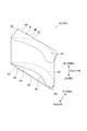
- the non-supporting wall 18 is an annular plate provided on the outer peripheral side of the turbine rotor 2 so as to face the supporting wall 16.
- the non-supporting wall 18 forms a flow passage wall 32 on the other side (the opposite side to the bearing housing 10 in the illustrated embodiment) of the exhaust gas flow passage 26 and does not support each of the nozzle vanes 14.
- the non-supporting wall 18 forms a shroud wall 34 on the downstream side of the flow path wall 32 facing the tip end of the blade of the turbine rotor 2 via a gap.
- the support wall 16 and the non-support wall 18 are connected by a plurality of nozzle supports 24.
- the back plate 23 is provided so as not to leak.
- the back plate 23 contacts the support wall 16 at one end in the axial direction, and contacts the bearing housing 10 at the other end in the axial direction.
- the drive ring 22 is rotationally driven by a driving force transmitted from an actuator (not shown).
- the lever plate 20 engaged with the drive ring 22 pivots the shaft portion 15 of the nozzle vane 14, and as a result, the nozzle vane 14 pivots and the blade angle of the nozzle vane 14 changes.
- the flow of exhaust gas from the scroll passage 4 to the turbine rotor 2 is adjusted.
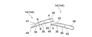
- FIG. 2 is a schematic perspective view of a nozzle vane 14 (14A) according to an embodiment.
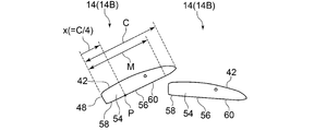
- FIG. 3 is a view showing the wing profile 36 at a central position in the wing height direction of the nozzle vanes 14 (14A).
- FIG. 4 is a view showing the shape of the end face 38 on the non-supporting wall 18 side of the nozzle vanes 14 (14A).
- FIG. 5 is a view showing the shape of the end surface 54 on the support wall 16 side of the nozzle vane 14 (14A).
- the display of the axial part 15 of the nozzle vane 14 is abbreviate
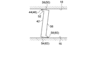
- FIG. 6 is a cross-sectional view taken along the line AA of FIG.
- FIG. 7 is a cross-sectional view taken along the line BB in FIG. 3, and is a view showing a state where the nozzle vanes 14 (14A) are not inclined by fluid force.
- FIG. 8 is a sectional view taken along the line AA of FIG. 3, and is a view showing a state where the nozzle vanes 14 (14A) are inclined by fluid force.
- FIG. 9 is a cross-sectional view taken along the line BB in FIG. 3, showing the nozzle vanes 14 (14A) inclined by fluid force.
- the edge 44 on the pressure surface 42 side of the end surface 38 on the non-supporting wall 18 side of the nozzle vane 14 (14 A) is straight
- the non-supporting wall side straight portion 46 is formed in
- the edge 44 on the pressure surface 42 side of the end surface 38 on the non-supporting wall 18 side of the nozzle vane 14 (14A) has the non-supporting wall-side straight portion 46 formed in a straight line,
- the nozzle vanes 14 are hydraulically inclined (see FIGS. 8 and 9)
- the non-supporting wall 18 side end face 38 and the non-supporting wall 18 of the nozzle vanes 14 extend over the entire length of the non-supporting wall side linear portion 46. Clearance can be reduced uniformly. Thereby, the clearance flow which flows between the end surface 38 side by the side of the non-supporting wall 18 of the nozzle vane 14 and the non-supporting wall 18 can be suppressed, and the loss by clearance flow can be reduced.
- the turbine performance can be improved when the opening degree of the nozzle vanes 14 is small. Further, as shown in FIGS. 6 and 7, since the clearance between the non-supporting wall 18 and the end face 38 on the non-supporting wall 18 side of the nozzle vane 14 when the nozzle vanes 14 are not inclined can be secured Occurrence can be suppressed.
- the non-supporting wall side straight portion 46 has a cord direction distance x from the trailing edge 48 of the nozzle vane 14 at the pressure surface 42 side edge 44 of the nozzle vane 14. It is formed in the range including the position P which is 1 ⁇ 4 of the code length C. In the illustrated exemplary embodiment, the non-supporting wall-side straight portion 46 is formed over the entire edge 44 on the pressure surface 42 side.
- the non-supporting wall side linear portion 46 is formed in a range including the trailing edge 48 side where the blade thickness is small and the clearance flow is a problem, the end face 38 side of the nozzle vane 14 on the nonsupporting wall 18 side The clearance flow between the non-supporting wall 18 can be effectively suppressed.
- the length L of the non-supporting wall-side straight portion 46 is half or more of the cord length C (vane length) of the nozzle vane 14. In the illustrated form, the length L is equal to the code length C.
- the non-supporting wall-side straight portion 46 is provided in most of the edge 44 on the pressure surface 42 side in the cord direction, so the end face 38 and the non-supporting wall of the nozzle vane 14 on the non-supporting wall 18 side The clearance flow between 18 and 18 can be effectively suppressed.
- the non-supporting wall-side end 50 of the nozzle vane 14 on the non-supporting wall 18 The non-supporting wall-side straight portion 46 is formed at the tip of the non-supporting wall-side rib-like portion 52, including 52.
- the central position of the nozzle vanes 14 in the blade height direction can obtain the effect of reducing the clearance flow by the non-supporting wall side straight portion 46 while maintaining the shape excellent in aerodynamic performance.
- the non-supporting wall side rib-like portion 52 has the non-supporting wall side linear part 46 as the pressure surface 42 of the nozzle vane 14 when viewed in the rotational axis direction of the nozzle vane 14. It is provided so as to extend on a tangent to it.
- the edge 58 on the negative pressure surface 56 side of the end surface 54 on the support wall 16 side of the nozzle vane 14 is a straight support wall It has a straight portion 60.
- the nozzle vane 14 flows as shown in FIGS. 8 and 9.
- the clearance between the end surface 54 on the support wall 16 side of the nozzle vane 14 and the support wall 16 can be uniformly reduced.
- the clearance flow which flows between the end face 54 by the side of support wall 16 of nozzle vane 14 and support wall 16 can be controlled, and the loss by clearance flow can be reduced.
- the turbine performance can be improved when the opening degree of the nozzle vanes 14 is small.
- FIGS. 6 and 7 since the clearance between the support wall 16 and the end face 54 on the support wall 16 side of the nozzle vane 14 when the nozzle vane 14 is not inclined can be secured, the stick of the nozzle vane 14 is generated. It can be suppressed.
- the non-supporting wall side straight portion 46 is supported on the supporting wall side before coming into contact with the non-supporting wall 18.
- the linear portion 60 is configured to abut on the support wall 16. Therefore, the axial movement amount of the entire nozzle vane 14 along with the inclination of the nozzle vane 14 can be set by the distance between the rotation center of the nozzle vane 14 and the support wall side linear portion 60. Further, the distance between the non-supporting wall 18 side end face 54 of the nozzle vane 14 and the non-supporting wall 18 when the nozzle vane 14 is inclined is determined by the distance between the rotation center of the nozzle vane 14 and the non-supporting wall side linear portion 46. It can be set.
- the support wall side straight portion 60 and the non-support wall side straight portion 46 are formed in parallel.
- the support wall side linear portion 60 has a position P where the cord direction distance x from the trailing edge 48 of the nozzle vane 14 is 1 ⁇ 4 of the cord length C of the nozzle vane 14 It is formed in the included range.
- the length M of the support wall side straight portion 60 is half or more of the cord length C (vane length) of the nozzle vanes 14.
- 0.8C ⁇ M ⁇ C is satisfied in the illustrated exemplary form.
- the support wall side linear portion 60 is provided in most of the edge 58 on the negative pressure surface 56 side in the cord direction, so the end surface 54 of the nozzle vane 14 on the support wall 16 side and the support wall 16 The clearance flow between them can be effectively suppressed.
- the length L of the non-supporting wall side straight portion 46 is larger than the length M of the supporting wall side straight portion 60.
- the loss due to the clearance flow can be effectively reduced by the simple configuration by enhancing the effect of uniformly reducing the clearance on the non-support wall 18 side where the clearance flow tends to be a problem when the nozzle vanes 14 are inclined. can do.
- the end portion 62 of the nozzle vane 14 on the support wall 16 side includes a support wall rib 64 projecting toward the negative pressure surface 56 of the nozzle vane 14, and the support wall side straight
- the shape portion 60 is formed at the tip of the support wall side rib shaped portion 64.
- the support wall side rib-shaped portion 64 so as to form the support wall side linear portion 60, as shown in FIG. 3, the wing profile at the center position in the wing height direction of the nozzle vane 14 While maintaining the shape excellent in aerodynamic performance, the reduction effect of the clearance flow by providing the support wall side linear portion 60 can be obtained.
- the support wall side linear portion 60 is attached to the suction surface 56 of the nozzle vane 14 in the rotational axis direction of the nozzle vane 14. It protrudes so as to extend on a tangent line.
- FIG. 10 is a schematic perspective view of a nozzle vane 14 (14B) according to an embodiment.
- FIG. 11 is a view showing the wing profile 36 at a central position in the wing height direction of the nozzle vanes 14 (14B).
- FIG. 12 is a view showing the shape of the end face 38 on the non-supporting wall 18 side of the nozzle vane 14 (14B).
- FIG. 13 is a view showing the shape of the end surface 54 on the support wall 16 side of the nozzle vanes 14 (14B).
- FIG. 14 is a cross-sectional view taken along the line AA of FIG. 11, showing the nozzle vanes 14 (14B) not inclined by fluid force.
- FIG. 15 shows a cross section taken along the line BB in FIG.
- FIG. 16 is a cross-sectional view taken along the line AA of FIG. 11, showing the nozzle vanes 14 (14B) inclined by fluid force.
- FIG. 17 is a cross-sectional view taken along the line BB in FIG. 11, showing the nozzle vanes 14 (14B) inclined by fluid force.
- the end 50 on the non-supporting wall 18 side of the nozzle vane 14 connects the end face 38 on the non-supporting wall 18 side of the nozzle vane 14 and the pressure surface 42.
- the non-supporting wall side inclined surface 66 is inclined so that the distance from the non-supporting wall 18 to the suction surface 56 of the nozzle vane 14 becomes smaller as the non-supporting wall 18 approaches the non-supporting wall side.
- the portion 46 is formed at a boundary position between the non-supporting wall-side inclined surface 66 and the end surface 38 on the non-supporting wall 18 side.
- the non-supporting wall-side inclined surface 66 is a plane.
- the non-supporting wall side straight portion 46 is formed at the boundary position between the non-supporting wall side inclined surface 66 and the end face 38 on the non-supporting wall 18 side, as shown in FIGS.
- the clearance between the end surface 54 on the support wall 16 side of the nozzle vane 14 and the support wall 16 can be uniformly reduced when the fluid port 14 is inclined by fluid force.
- the clearance flow which flows between the end face 54 by the side of support wall 16 of nozzle vane 14 and support wall 16 can be controlled, and the loss by clearance flow can be reduced.
- the turbine performance can be improved when the opening degree of the nozzle vanes 14 is small.
- FIGS. 16 and 17 since the clearance between the support wall 16 and the end face 54 on the support wall 16 side of the nozzle vane 14 when the nozzle vane 14 is not inclined can be secured, the stick of the nozzle vane 14 is generated. It can be suppressed.
- the cord direction distance x from the trailing edge 48 of the nozzle vane 14 in the edge portion 44 on the pressure surface 42 side It is formed in the range including the position P which is 1 ⁇ 4 of the code length C.
- the non-supporting wall-side straight portion 46 is formed over the entire edge 44 on the pressure surface 42 side.
- the length L of the non-supporting wall side straight portion 46 is half or more of the cord length C (vane length) of the nozzle vanes 14. In the illustrated exemplary embodiment, 0.8C ⁇ L ⁇ C is satisfied.
- the edge 58 on the negative pressure surface 56 side of the end surface 54 on the support wall 16 side of the nozzle vane 14 is a straight support wall It has a straight portion 60.
- the edge 58 on the negative pressure surface 56 side of the end surface 54 on the support wall 16 side of the nozzle vane 14 is formed in a straight line, so the nozzle vane 14 flows as shown in FIG. 16 and FIG.
- the clearance between the end surface 54 on the support wall 16 side of the nozzle vane 14 and the support wall 16 can be uniformly reduced.
- the clearance flow which flows between the end face 54 by the side of support wall 16 of nozzle vane 14 and support wall 16 can be controlled, and the loss by clearance flow can be reduced.
- the turbine performance can be improved when the opening degree of the nozzle vanes 14 is small.
- FIGS. 14 and 15 since the clearance between the support wall 16 and the end face 54 on the support wall 16 side of the nozzle vane 14 when the nozzle vanes 14 are not inclined can be secured, the stick of the nozzle vane 14 is generated. It can be suppressed.
- the support wall side straight portion 60 and the non-support wall side straight portion 46 are formed in parallel.
- the support wall side straight portion 60 has a position P where the cord direction distance x from the trailing edge 48 of the nozzle vane 14 is 1 ⁇ 4 of the cord length C of the nozzle vane 14 It is formed in the included range.
- the length M of the support wall side straight portion 60 is half or more of the cord length C (vane length) of the nozzle vanes 14.
- the support wall side linear portion 60 is provided in most of the edge 58 on the negative pressure surface 56 side in the cord direction, so the end surface 54 of the nozzle vane 14 on the support wall 16 side and the support wall 16 The clearance flow between them can be effectively suppressed.
- the length L of the non-supporting wall side straight portion 46 is larger than the length M of the supporting wall side straight portion 60.
- the loss due to the clearance flow can be effectively reduced by the simple configuration by enhancing the effect of uniformly reducing the clearance on the non-support wall 18 side where the clearance flow tends to be a problem when the nozzle vanes 14 are inclined. can do.
- the end portion 62 of the nozzle vane 14 on the support wall 16 side is a support wall rib 64 projecting toward the negative pressure surface 56 of the nozzle vane 14
- the support wall side straight portion 60 is formed at the tip of the support wall side rib-like portion 64.
- the support wall side rib shaped portion 64 so as to form the support wall side linear portion 60, as shown in FIG. 11, the wing profile at the center position in the wing height direction of the nozzle vane 14 While maintaining the shape excellent in aerodynamic performance, the reduction effect of the clearance flow by providing the support wall side linear portion 60 can be obtained.
- the present invention is not limited to the above-described embodiments, and includes the embodiments in which the above-described embodiments are modified or the embodiments in which these embodiments are appropriately combined.
- FIG. 15 and the like show an example in which the nozzle vanes 14 have non-supporting wall side inclined surfaces 66
- the nozzle vanes 14 have supporting wall side inclined surfaces 68 as shown in FIG. May be
- the end portion 62 on the support wall 16 side of the nozzle vane 14 includes a support wall side inclined surface 68 connecting the end face 54 on the support wall 16 side of the nozzle vane 14 and the suction surface 56.
- the inclined surface 68 is inclined such that the distance between the inclined surface 68 and the pressure surface 42 of the nozzle vane 14 decreases as the support wall 16 is approached.
- the support wall side linear portion 60 is formed at the boundary position between the support wall side inclined surface 68 and the end surface 54 on the support wall 16 side.
- the clearance between the end face 54 on the support wall 16 side of the nozzle vanes 14 and the support wall 16 can be uniformly reduced.
- the clearance flow which flows between the end face 54 by the side of support wall 16 of nozzle vane 14 and support wall 16 can be controlled, and the loss by clearance flow can be reduced.
- the turbine performance can be improved when the opening degree of the nozzle vanes 14 is small.
- the clearance between the support wall 16 and the end surface 54 on the support wall 16 side of the nozzle vane 14 when the nozzle vane 14 is not inclined can be secured, the generation of the stick of the nozzle vane 14 can be suppressed.
- the non-supporting wall side rib-like portion 52 is the pressure surface 42 of the nozzle vane 14 when the non-supporting wall side linear portion 46 is viewed in the rotational axis direction of the nozzle vane 14. It was projected to extend on a tangent to the
- the present invention is not limited thereto.
- the non-supporting wall-side rib-like portion 52 is a nozzle vane when the non-supporting wall-side straight portion 46 is viewed in the rotational axis direction of the nozzle vane 14 It may be projected to extend on a straight line separated from the pressure surface 42 of 14.
- the support wall side straight part 60 is not exposed to the suction surface 56 of the nozzle vane 14 in the rotational axis direction of the nozzle vane 14. It was projected to extend on a tangent line.
- the present invention is not limited thereto.
- the support wall side rib shaped part 64 has the support wall side straight part 60 as the nozzle vane 14 as viewed in the rotational axis direction of the nozzle vane 14. It may be projected to extend on a straight line separated from the suction surface 56.
- the nozzle vanes 14 are supported in a cantilever manner on the flow passage wall 28 on the bearing housing 10 side in the axial direction of the exhaust gas flow passage 26.
- the present invention is not limited to this, and the nozzle vanes 14 may be cantilevered on the flow passage wall 32 on the opposite side of the bearing housing 10 in the axial direction of the exhaust gas flow passage 26. That is, the support wall rotatably supporting the nozzle vanes may be a flow passage wall on the opposite side to the bearing housing in the axial direction in the exhaust gas flow passage.
Landscapes
- Engineering & Computer Science (AREA)
- Chemical & Material Sciences (AREA)
- Mechanical Engineering (AREA)
- General Engineering & Computer Science (AREA)
- Combustion & Propulsion (AREA)
- Physics & Mathematics (AREA)
- Fluid Mechanics (AREA)
- Chemical Kinetics & Catalysis (AREA)
- General Chemical & Material Sciences (AREA)
- Supercharger (AREA)
Abstract
Description
例えば、「ある方向に」、「ある方向に沿って」、「平行」、「直交」、「中心」、「同心」或いは「同軸」等の相対的或いは絶対的な配置を表す表現は、厳密にそのような配置を表すのみならず、公差、若しくは、同じ機能が得られる程度の角度や距離をもって相対的に変位している状態も表すものとする。
例えば、「同一」、「等しい」及び「均質」等の物事が等しい状態であることを表す表現は、厳密に等しい状態を表すのみならず、公差、若しくは、同じ機能が得られる程度の差が存在している状態も表すものとする。
例えば、四角形状や円筒形状等の形状を表す表現は、幾何学的に厳密な意味での四角形状や円筒形状等の形状を表すのみならず、同じ効果が得られる範囲で、凹凸部や面取り部等を含む形状も表すものとする。
一方、一の構成要素を「備える」、「具える」、「具備する」、「含む」、又は、「有する」という表現は、他の構成要素の存在を除外する排他的な表現ではない。
4 スクロール流路
6 タービンハウジング
8 軸受
10 軸受ハウジング
12 可変ノズル機構
14 ノズルベーン
15 軸部
16 支持壁
18 非支持壁
20 レバープレート
22 ドライブリング
23 バックプレート
24 ノズルサポート
26 排ガス流路
28 流路壁
30 支持穴
32 流路壁
34 シュラウド壁
36 翼プロファイル
38 端面
42 圧力面
44 縁部
46 非支持壁側直線状部
48 縁
50 端部
52 非支持壁側リブ状部
54 端面
56 負圧面
58 縁部
60 支持壁側直線状部
62 端部
64 支持壁側リブ状部
66 非支持壁側傾斜面
68 支持壁側傾斜面
100 可変容量型ターボチャージャ
C コード長
P 位置
x コード方向距離
Claims (12)
- タービンロータと、前記タービンロータの外周側に形成されるスクロール流路から前記タービンロータへの排ガスの流れを調整するための可変ノズル機構と、を備える可変容量型ターボチャージャであって、
前記可変ノズル機構は、
前記スクロール流路から前記タービンロータへ前記排ガスを導くための排ガス流路に設けられるノズルベーンと、
前記排ガス流路のうち前記タービンロータの軸方向における一方側の流路壁を形成するとともに前記ノズルベーンを回動可能に片持ち支持する支持壁と、
前記排ガス流路のうち前記軸方向における他方側の流路壁を形成する非支持壁と、
を含み、
前記ノズルベーンにおける前記非支持壁側の端面のうち圧力面側の縁部は、直線状に形成された非支持壁側直線状部を有する、可変容量型ターボチャージャ。 - 前記非支持壁側直線状部は、前記圧力面側の前記縁部のうち、前記ノズルベーンの後縁からのコード方向距離が前記ノズルベーンのコード長の1/4となる位置を含む範囲に形成された、請求項1に記載の可変容量型ターボチャージャ。
- 前記非支持壁側直線状部の長さは、前記ノズルベーンのコード長の半分以上である、請求項1又は2に記載の可変容量型ターボチャージャ。
- 前記ノズルベーンにおける前記非支持壁側の端部は、前記ノズルベーンの圧力面側に突出する非支持壁側リブ状部を含み、
前記非支持壁側直線状部は、前記非支持壁側リブ状部の先端部に形成された、請求項1乃至3の何れか1項に記載の可変容量型ターボチャージャ。 - 前記ノズルベーンにおける前記非支持壁側の端部は、前記ノズルベーンにおける前記非支持壁側の端面と前記圧力面とを接続する非支持壁側傾斜面を含み、
前記非支持壁側傾斜面は、前記非支持壁に近づくにつれて前記ノズルベーンの負圧面との距離が小さくなるように傾斜しており、
前記非支持壁側直線状部は、前記非支持壁側傾斜面と前記非支持壁側の前記端面との境界位置に形成された、請求項1乃至3の何れか1項に記載の可変容量型ターボチャージャ。 - 前記ノズルベーンにおける前記支持壁側の端面のうち負圧面側の縁部は、直線状に形成された支持壁側直線状部を有する、請求項1乃至5の何れか1項に記載の可変容量型ターボチャージャ。
- 前記支持壁側直線状部と前記非支持壁側直線状部とは、平行に形成された、請求項6に記載の可変容量型ターボチャージャ。
- 前記支持壁側直線状部は、前記ノズルベーンの後縁からのコード方向距離が前記ノズルベーンのコード長の1/4となる位置を含む範囲に形成された、請求項6又は7に記載の可変容量型ターボチャージャ。
- 前記支持壁側直線状部の長さは、前記ノズルベーンのコード長の半分以上である、請求項6乃至8の何れか1項に記載の可変容量型ターボチャージャ。
- 前記非支持壁側直線状部は、前記支持壁側直線状部より長い、請求項6乃至9の何れか1項に記載の可変容量型ターボチャージャ。
- 前記ノズルベーンにおけるにおける前記支持壁側の端部は、前記ノズルベーンの負圧面側に突出する支持壁側リブ状部を含み、
前記支持壁側直線状部は、前記支持壁側リブ状部に形成された、請求項6乃至10の何れか1項に記載の可変容量型ターボチャージャ。 - 前記ノズルベーンにおける前記支持壁側の端部は、前記ノズルベーンにおける前記支持壁側の端面と前記圧力面とを接続する支持壁側傾斜面を含み、
前記支持壁側傾斜面は、前記支持壁に近づくにつれて前記ノズルベーンの圧力面との距離が小さくなるように傾斜しており、
前記支持壁側直線状部は、前記支持壁側傾斜面と前記支持壁側の前記端面との境界位置に形成された、請求項6乃至10の何れか1項に記載の可変容量型ターボチャージャ。
Priority Applications (6)
| Application Number | Priority Date | Filing Date | Title |
|---|---|---|---|
| CN201680084147.0A CN109312658B (zh) | 2016-03-30 | 2016-03-30 | 可变容量型涡轮增压器 |
| EP21200499.8A EP3954882B1 (en) | 2016-03-30 | 2016-03-30 | Variable geometry turbocharger |
| EP16896865.9A EP3421754B1 (en) | 2016-03-30 | 2016-03-30 | Variable geometry turbocharger |
| US16/088,539 US11092068B2 (en) | 2016-03-30 | 2016-03-30 | Variable geometry turbocharger |
| JP2018507949A JP6694950B2 (ja) | 2016-03-30 | 2016-03-30 | 可変容量型ターボチャージャ |
| PCT/JP2016/060466 WO2017168646A1 (ja) | 2016-03-30 | 2016-03-30 | 可変容量型ターボチャージャ |
Applications Claiming Priority (1)
| Application Number | Priority Date | Filing Date | Title |
|---|---|---|---|
| PCT/JP2016/060466 WO2017168646A1 (ja) | 2016-03-30 | 2016-03-30 | 可変容量型ターボチャージャ |
Publications (1)
| Publication Number | Publication Date |
|---|---|
| WO2017168646A1 true WO2017168646A1 (ja) | 2017-10-05 |
Family
ID=59962805
Family Applications (1)
| Application Number | Title | Priority Date | Filing Date |
|---|---|---|---|
| PCT/JP2016/060466 Ceased WO2017168646A1 (ja) | 2016-03-30 | 2016-03-30 | 可変容量型ターボチャージャ |
Country Status (5)
| Country | Link |
|---|---|
| US (1) | US11092068B2 (ja) |
| EP (2) | EP3954882B1 (ja) |
| JP (1) | JP6694950B2 (ja) |
| CN (1) | CN109312658B (ja) |
| WO (1) | WO2017168646A1 (ja) |
Families Citing this family (3)
| Publication number | Priority date | Publication date | Assignee | Title |
|---|---|---|---|---|
| DE102018211673A1 (de) * | 2018-07-12 | 2020-01-16 | Continental Automotive Gmbh | Leitschaufel und mit einer solchen versehene Turbinenanordnung |
| US11946377B2 (en) * | 2020-02-17 | 2024-04-02 | Mitsubishi Heavy Industries Engine & Turbocharger, Ltd. | Variable nozzle device, turbine, and turbocharger |
| CN119053772A (zh) * | 2022-05-25 | 2024-11-29 | 株式会社Ihi | 涡轮机以及增压器 |
Citations (4)
| Publication number | Priority date | Publication date | Assignee | Title |
|---|---|---|---|---|
| JPS6065207A (ja) * | 1983-09-21 | 1985-04-15 | Nissan Motor Co Ltd | 可変容量ラジアルタ−ビン |
| JPH11229815A (ja) * | 1998-02-16 | 1999-08-24 | Ishikawajima Harima Heavy Ind Co Ltd | 可変容量型タービン |
| JP2010112223A (ja) * | 2008-11-05 | 2010-05-20 | Ihi Corp | ターボチャージャ |
| DE102011077135A1 (de) * | 2011-06-07 | 2012-12-13 | Bosch Mahle Turbo Systems Gmbh & Co. Kg | Variable Turbinen-/Verdichtergeometrie |
Family Cites Families (62)
| Publication number | Priority date | Publication date | Assignee | Title |
|---|---|---|---|---|
| US2314572A (en) * | 1938-12-07 | 1943-03-23 | Herman E Chitz | Turboengine |
| US3101926A (en) * | 1960-09-01 | 1963-08-27 | Garrett Corp | Variable area nozzle device |
| US3269701A (en) * | 1963-10-17 | 1966-08-30 | Carrier Corp | Stator blade support |
| GB1049080A (en) * | 1963-12-02 | 1966-11-23 | Gen Electric | Improvements in adjustable stator vanes |
| US3314654A (en) * | 1965-07-30 | 1967-04-18 | Gen Electric | Variable area turbine nozzle for axial flow gas turbine engines |
| US3295827A (en) * | 1966-04-06 | 1967-01-03 | Gen Motors Corp | Variable configuration blade |
| US3990810A (en) * | 1975-12-23 | 1976-11-09 | Westinghouse Electric Corporation | Vane assembly for close coupling the compressor turbine and a single stage power turbine of a two-shaped gas turbine |
| US4307994A (en) * | 1979-10-15 | 1981-12-29 | General Motors Corporation | Variable vane position adjuster |
| FR2524934B1 (fr) * | 1982-04-08 | 1986-12-26 | Snecma | Dispositif de butee de securite pour pivot d'aubes de stator a calage variable |
| JPS61126001U (ja) * | 1985-01-29 | 1986-08-07 | ||
| US4652208A (en) * | 1985-06-03 | 1987-03-24 | General Electric Company | Actuating lever for variable stator vanes |
| FR2586268B1 (fr) * | 1985-08-14 | 1989-06-09 | Snecma | Dispositif de variation de la section de passage d'un distributeur de turbine |
| US4863348A (en) * | 1987-02-06 | 1989-09-05 | Weinhold Wolfgang P | Blade, especially a rotor blade |
| US4874289A (en) * | 1988-05-26 | 1989-10-17 | United States Of America As Represented By The Secretary Of The Air Force | Variable stator vane assembly for a rotary turbine engine |
| FR2646467A1 (fr) * | 1989-04-26 | 1990-11-02 | Snecma | Aube de stator a calage variable a coupelle rapportee |
| US5316443A (en) * | 1991-10-04 | 1994-05-31 | Chemineer, Inc. | Reversible mixing impeller |
| FR2696500B1 (fr) * | 1992-10-07 | 1994-11-25 | Snecma | Turbomachine équipée de moyens de réglage du jeu entre les redresseurs et le rotor d'un compresseur. |
| US5261227A (en) * | 1992-11-24 | 1993-11-16 | General Electric Company | Variable specific thrust turbofan engine |
| US5672047A (en) * | 1995-04-12 | 1997-09-30 | Dresser-Rand Company | Adjustable stator vanes for turbomachinery |
| US6086328A (en) * | 1998-12-21 | 2000-07-11 | General Electric Company | Tapered tip turbine blade |
| FR2814205B1 (fr) * | 2000-09-18 | 2003-02-28 | Snecma Moteurs | Turbomachine a veine d'ecoulement ameliore |
| JP2002213206A (ja) * | 2001-01-12 | 2002-07-31 | Mitsubishi Heavy Ind Ltd | ガスタービンにおける翼構造 |
| DE10355241A1 (de) * | 2003-11-26 | 2005-06-30 | Rolls-Royce Deutschland Ltd & Co Kg | Strömungsarbeitsmaschine mit Fluidzufuhr |
| US7255530B2 (en) * | 2003-12-12 | 2007-08-14 | Honeywell International Inc. | Vane and throat shaping |
| FR2864990B1 (fr) * | 2004-01-14 | 2008-02-22 | Snecma Moteurs | Perfectionnements apportes aux fentes d'evacuation de l'air de refroidissement d'aubes de turbine haute-pression |
| US7360990B2 (en) * | 2004-10-13 | 2008-04-22 | General Electric Company | Methods and apparatus for assembling gas turbine engines |
| FR2883599B1 (fr) * | 2005-03-23 | 2010-04-23 | Snecma Moteurs | Dispositif de liaison entre une enceinte de passage d'air de refroidissement et un aubage de distributeur dans une turbomachine |
| US7452182B2 (en) * | 2005-04-07 | 2008-11-18 | Siemens Energy, Inc. | Multi-piece turbine vane assembly |
| FR2885645A1 (fr) * | 2005-05-13 | 2006-11-17 | Snecma Moteurs Sa | Aube creuse de rotor pour la turbine d'un moteur a turbine a gaz, equipee d'une baignoire |
| US7628579B2 (en) * | 2005-07-20 | 2009-12-08 | United Technologies Corporation | Gear train variable vane synchronizing mechanism for inner diameter vane shroud |
| DE102005040574A1 (de) * | 2005-08-26 | 2007-03-15 | Rolls-Royce Deutschland Ltd & Co Kg | Spaltkontrollvorrichtung für eine Gasturbine |
| GB0519502D0 (en) * | 2005-09-24 | 2005-11-02 | Rolls Royce Plc | Vane assembly |
| DE102005060699A1 (de) * | 2005-12-19 | 2007-06-21 | Rolls-Royce Deutschland Ltd & Co Kg | Strömungsarbeitsmaschine mit Verstellstator |
| FR2899637B1 (fr) * | 2006-04-06 | 2010-10-08 | Snecma | Aube de stator a calage variable de turbomachine |
| US7806653B2 (en) * | 2006-12-22 | 2010-10-05 | General Electric Company | Gas turbine engines including multi-curve stator vanes and methods of assembling the same |
| EP2118468A4 (en) * | 2007-02-15 | 2014-12-24 | Borgwarner Inc | TURBOCOMPRESSOR DAWN |
| US7670107B2 (en) * | 2007-03-26 | 2010-03-02 | Honeywell International Inc. | Variable-vane assembly having fixed axial-radial guides and fixed radial-only guides for unison ring |
| DE102008017844A1 (de) * | 2008-04-08 | 2009-10-15 | Rolls-Royce Deutschland Ltd & Co Kg | Strömungsmaschine mit Fluid-Injektorbaugruppe |
| CN102057134B (zh) * | 2008-10-30 | 2015-04-22 | 三菱日立电力系统株式会社 | 具有削薄接片的涡轮动叶片 |
| EP2351920B1 (en) * | 2008-11-05 | 2016-04-13 | IHI Corporation | Turbocharger |
| EP2309098A1 (en) * | 2009-09-30 | 2011-04-13 | Siemens Aktiengesellschaft | Airfoil and corresponding guide vane, blade, gas turbine and turbomachine |
| JP5603800B2 (ja) * | 2011-02-22 | 2014-10-08 | 株式会社日立製作所 | タービン静翼、およびそれを用いた蒸気タービン設備 |
| DE102011083778A1 (de) * | 2011-09-29 | 2013-04-04 | Rolls-Royce Deutschland Ltd & Co Kg | Schaufel einer Rotor- oder Statorreihe für den Einsatz in einer Strömungsmaschine |
| WO2013084260A1 (ja) * | 2011-12-07 | 2013-06-13 | 株式会社 日立製作所 | タービン動翼 |
| KR101959315B1 (ko) * | 2012-01-13 | 2019-07-02 | 보르그워너 인코퍼레이티드 | 홈이 형성된 가이드 베인을 가진 가변 터빈 구조를 구비한 터보차저 |
| FR2989107B1 (fr) * | 2012-04-04 | 2017-03-31 | Snecma | Aube de rotor de turbomachine |
| SG11201501228YA (en) * | 2012-08-22 | 2015-04-29 | United Technologies Corp | Compliant cantilevered airfoil |
| WO2014061094A1 (ja) * | 2012-10-16 | 2014-04-24 | 三菱電機株式会社 | ターボファンおよび空気調和機 |
| EP2738356B1 (fr) * | 2012-11-29 | 2019-05-01 | Safran Aero Boosters SA | Aube de redresseur de turbomachine, redresseur de turbomachine et procédé de montage associé |
| US10385765B2 (en) * | 2012-12-27 | 2019-08-20 | Mitsubishi Heavy Industries Engine & Turbocharger, Ltd. | Variable geometry turbocharger |
| EP3068977B1 (en) * | 2013-11-14 | 2019-07-10 | United Technologies Corporation | Gas turbine vane assembly comprising a rotatable vane with protrusions on the pressure or suction side |
| US9638212B2 (en) * | 2013-12-19 | 2017-05-02 | Pratt & Whitney Canada Corp. | Compressor variable vane assembly |
| US9533485B2 (en) * | 2014-03-28 | 2017-01-03 | Pratt & Whitney Canada Corp. | Compressor variable vane assembly |
| US10107108B2 (en) * | 2015-04-29 | 2018-10-23 | General Electric Company | Rotor blade having a flared tip |
| US20160319672A1 (en) * | 2015-04-29 | 2016-11-03 | General Electric Company | Rotor blade having a flared tip |
| CN204899986U (zh) * | 2015-08-14 | 2015-12-23 | 宁波威孚天力增压技术有限公司 | 一种能够减少漏气的涡轮增压器涡轮端结构 |
| WO2017216937A1 (ja) * | 2016-06-16 | 2017-12-21 | 三菱電機株式会社 | 翼車及び軸流送風機 |
| ES2881788T3 (es) * | 2016-09-02 | 2021-11-30 | Lm Wind Power Int Tech Ii Aps | Sistema de transporte y almacenamiento para una pala de turbina eólica |
| US20180073370A1 (en) * | 2016-09-14 | 2018-03-15 | Rolls-Royce Plc | Turbine blade cooling |
| US11168702B2 (en) * | 2017-08-10 | 2021-11-09 | Raytheon Technologies Corporation | Rotating airfoil with tip pocket |
| KR20190096569A (ko) * | 2018-02-09 | 2019-08-20 | 두산중공업 주식회사 | 가스 터빈 |
| KR102113682B1 (ko) * | 2018-10-01 | 2020-05-21 | 두산중공업 주식회사 | 터빈 블레이드 |
-
2016
- 2016-03-30 EP EP21200499.8A patent/EP3954882B1/en active Active
- 2016-03-30 CN CN201680084147.0A patent/CN109312658B/zh not_active Expired - Fee Related
- 2016-03-30 EP EP16896865.9A patent/EP3421754B1/en not_active Not-in-force
- 2016-03-30 WO PCT/JP2016/060466 patent/WO2017168646A1/ja not_active Ceased
- 2016-03-30 US US16/088,539 patent/US11092068B2/en not_active Expired - Fee Related
- 2016-03-30 JP JP2018507949A patent/JP6694950B2/ja not_active Expired - Fee Related
Patent Citations (4)
| Publication number | Priority date | Publication date | Assignee | Title |
|---|---|---|---|---|
| JPS6065207A (ja) * | 1983-09-21 | 1985-04-15 | Nissan Motor Co Ltd | 可変容量ラジアルタ−ビン |
| JPH11229815A (ja) * | 1998-02-16 | 1999-08-24 | Ishikawajima Harima Heavy Ind Co Ltd | 可変容量型タービン |
| JP2010112223A (ja) * | 2008-11-05 | 2010-05-20 | Ihi Corp | ターボチャージャ |
| DE102011077135A1 (de) * | 2011-06-07 | 2012-12-13 | Bosch Mahle Turbo Systems Gmbh & Co. Kg | Variable Turbinen-/Verdichtergeometrie |
Non-Patent Citations (1)
| Title |
|---|
| See also references of EP3421754A4 * |
Also Published As
| Publication number | Publication date |
|---|---|
| EP3954882A1 (en) | 2022-02-16 |
| US20200123966A1 (en) | 2020-04-23 |
| EP3954882B1 (en) | 2023-05-03 |
| EP3421754B1 (en) | 2021-12-01 |
| EP3421754A4 (en) | 2019-02-20 |
| EP3421754A1 (en) | 2019-01-02 |
| CN109312658B (zh) | 2022-02-22 |
| JPWO2017168646A1 (ja) | 2018-11-22 |
| CN109312658A (zh) | 2019-02-05 |
| US11092068B2 (en) | 2021-08-17 |
| JP6694950B2 (ja) | 2020-05-20 |
Similar Documents
| Publication | Publication Date | Title |
|---|---|---|
| JP5524010B2 (ja) | 可変容量タービン | |
| JP5651459B2 (ja) | タービンエンジンにおける圧縮機の動作に関するシステム及び装置 | |
| WO2008075467A1 (ja) | 軸流圧縮機の翼列 | |
| JP2021032106A (ja) | ベーンドディフューザ及び遠心圧縮機 | |
| JP6690730B2 (ja) | 可変ノズルユニットおよび過給機 | |
| JP6959992B2 (ja) | タービン及びターボチャージャ | |
| WO2017168646A1 (ja) | 可変容量型ターボチャージャ | |
| JPWO2018116394A1 (ja) | ターボチャージャ及びターボチャージャのノズルベーン並びにタービン | |
| JP6820161B2 (ja) | 可変ノズルベーン及び可変容量型ターボチャージャ | |
| JP2013015142A (ja) | タービンブレード | |
| JP5667039B2 (ja) | 圧縮機及びこれに用いる可変静翼 | |
| JP2020165374A (ja) | タービンおよび過給機 | |
| JP2013155640A (ja) | ターボ機械の可変静翼機構 | |
| JP6605147B2 (ja) | ターボチャージャ及びターボチャージャのノズルベーン並びにタービン | |
| JP5287329B2 (ja) | ポンプインペラ | |
| JP7165804B2 (ja) | ノズルベーン | |
| JP7661607B2 (ja) | 可変ノズル装置及び可変容量型ターボチャージャ | |
| WO2020100420A1 (ja) | ノズルベーン | |
| JP2012172573A (ja) | 流体機械 | |
| JP2008163761A (ja) | ラジアルタービン |
Legal Events
| Date | Code | Title | Description |
|---|---|---|---|
| WWE | Wipo information: entry into national phase |
Ref document number: 2018507949 Country of ref document: JP |
|
| WWE | Wipo information: entry into national phase |
Ref document number: 2016896865 Country of ref document: EP |
|
| NENP | Non-entry into the national phase |
Ref country code: DE |
|
| ENP | Entry into the national phase |
Ref document number: 2016896865 Country of ref document: EP Effective date: 20180924 |
|
| 121 | Ep: the epo has been informed by wipo that ep was designated in this application |
Ref document number: 16896865 Country of ref document: EP Kind code of ref document: A1 |