WO2017169218A1 - エゼクタ、エゼクタの製造方法及びディフューザの出口流路の設定方法 - Google Patents
エゼクタ、エゼクタの製造方法及びディフューザの出口流路の設定方法 Download PDFInfo
- Publication number
- WO2017169218A1 WO2017169218A1 PCT/JP2017/005468 JP2017005468W WO2017169218A1 WO 2017169218 A1 WO2017169218 A1 WO 2017169218A1 JP 2017005468 W JP2017005468 W JP 2017005468W WO 2017169218 A1 WO2017169218 A1 WO 2017169218A1
- Authority
- WO
- WIPO (PCT)
- Prior art keywords
- flow path
- ejector
- diffuser
- fluid
- attachment
- Prior art date
- Legal status (The legal status is an assumption and is not a legal conclusion. Google has not performed a legal analysis and makes no representation as to the accuracy of the status listed.)
- Ceased
Links
Images

Classifications
-
- F—MECHANICAL ENGINEERING; LIGHTING; HEATING; WEAPONS; BLASTING
- F04—POSITIVE - DISPLACEMENT MACHINES FOR LIQUIDS; PUMPS FOR LIQUIDS OR ELASTIC FLUIDS
- F04F—PUMPING OF FLUID BY DIRECT CONTACT OF ANOTHER FLUID OR BY USING INERTIA OF FLUID TO BE PUMPED; SIPHONS
- F04F5/00—Jet pumps, i.e. devices in which flow is induced by pressure drop caused by velocity of another fluid flow
- F04F5/14—Jet pumps, i.e. devices in which flow is induced by pressure drop caused by velocity of another fluid flow the inducing fluid being elastic fluid
- F04F5/16—Jet pumps, i.e. devices in which flow is induced by pressure drop caused by velocity of another fluid flow the inducing fluid being elastic fluid displacing elastic fluids
-
- F—MECHANICAL ENGINEERING; LIGHTING; HEATING; WEAPONS; BLASTING
- F04—POSITIVE - DISPLACEMENT MACHINES FOR LIQUIDS; PUMPS FOR LIQUIDS OR ELASTIC FLUIDS
- F04F—PUMPING OF FLUID BY DIRECT CONTACT OF ANOTHER FLUID OR BY USING INERTIA OF FLUID TO BE PUMPED; SIPHONS
- F04F5/00—Jet pumps, i.e. devices in which flow is induced by pressure drop caused by velocity of another fluid flow
- F04F5/14—Jet pumps, i.e. devices in which flow is induced by pressure drop caused by velocity of another fluid flow the inducing fluid being elastic fluid
- F04F5/16—Jet pumps, i.e. devices in which flow is induced by pressure drop caused by velocity of another fluid flow the inducing fluid being elastic fluid displacing elastic fluids
- F04F5/18—Jet pumps, i.e. devices in which flow is induced by pressure drop caused by velocity of another fluid flow the inducing fluid being elastic fluid displacing elastic fluids for compressing
-
- F—MECHANICAL ENGINEERING; LIGHTING; HEATING; WEAPONS; BLASTING
- F04—POSITIVE - DISPLACEMENT MACHINES FOR LIQUIDS; PUMPS FOR LIQUIDS OR ELASTIC FLUIDS
- F04F—PUMPING OF FLUID BY DIRECT CONTACT OF ANOTHER FLUID OR BY USING INERTIA OF FLUID TO BE PUMPED; SIPHONS
- F04F5/00—Jet pumps, i.e. devices in which flow is induced by pressure drop caused by velocity of another fluid flow
- F04F5/14—Jet pumps, i.e. devices in which flow is induced by pressure drop caused by velocity of another fluid flow the inducing fluid being elastic fluid
- F04F5/16—Jet pumps, i.e. devices in which flow is induced by pressure drop caused by velocity of another fluid flow the inducing fluid being elastic fluid displacing elastic fluids
- F04F5/20—Jet pumps, i.e. devices in which flow is induced by pressure drop caused by velocity of another fluid flow the inducing fluid being elastic fluid displacing elastic fluids for evacuating
-
- F—MECHANICAL ENGINEERING; LIGHTING; HEATING; WEAPONS; BLASTING
- F04—POSITIVE - DISPLACEMENT MACHINES FOR LIQUIDS; PUMPS FOR LIQUIDS OR ELASTIC FLUIDS
- F04F—PUMPING OF FLUID BY DIRECT CONTACT OF ANOTHER FLUID OR BY USING INERTIA OF FLUID TO BE PUMPED; SIPHONS
- F04F5/00—Jet pumps, i.e. devices in which flow is induced by pressure drop caused by velocity of another fluid flow
- F04F5/14—Jet pumps, i.e. devices in which flow is induced by pressure drop caused by velocity of another fluid flow the inducing fluid being elastic fluid
- F04F5/24—Jet pumps, i.e. devices in which flow is induced by pressure drop caused by velocity of another fluid flow the inducing fluid being elastic fluid displacing liquids, e.g. containing solids, or liquids and elastic fluids
-
- F—MECHANICAL ENGINEERING; LIGHTING; HEATING; WEAPONS; BLASTING
- F04—POSITIVE - DISPLACEMENT MACHINES FOR LIQUIDS; PUMPS FOR LIQUIDS OR ELASTIC FLUIDS
- F04F—PUMPING OF FLUID BY DIRECT CONTACT OF ANOTHER FLUID OR BY USING INERTIA OF FLUID TO BE PUMPED; SIPHONS
- F04F5/00—Jet pumps, i.e. devices in which flow is induced by pressure drop caused by velocity of another fluid flow
- F04F5/44—Component parts, details, or accessories not provided for in, or of interest apart from, groups F04F5/02 - F04F5/42
-
- F—MECHANICAL ENGINEERING; LIGHTING; HEATING; WEAPONS; BLASTING
- F04—POSITIVE - DISPLACEMENT MACHINES FOR LIQUIDS; PUMPS FOR LIQUIDS OR ELASTIC FLUIDS
- F04F—PUMPING OF FLUID BY DIRECT CONTACT OF ANOTHER FLUID OR BY USING INERTIA OF FLUID TO BE PUMPED; SIPHONS
- F04F5/00—Jet pumps, i.e. devices in which flow is induced by pressure drop caused by velocity of another fluid flow
- F04F5/44—Component parts, details, or accessories not provided for in, or of interest apart from, groups F04F5/02 - F04F5/42
- F04F5/46—Arrangements of nozzles
-
- F—MECHANICAL ENGINEERING; LIGHTING; HEATING; WEAPONS; BLASTING
- F04—POSITIVE - DISPLACEMENT MACHINES FOR LIQUIDS; PUMPS FOR LIQUIDS OR ELASTIC FLUIDS
- F04F—PUMPING OF FLUID BY DIRECT CONTACT OF ANOTHER FLUID OR BY USING INERTIA OF FLUID TO BE PUMPED; SIPHONS
- F04F5/00—Jet pumps, i.e. devices in which flow is induced by pressure drop caused by velocity of another fluid flow
- F04F5/44—Component parts, details, or accessories not provided for in, or of interest apart from, groups F04F5/02 - F04F5/42
- F04F5/46—Arrangements of nozzles
- F04F5/461—Adjustable nozzles
-
- F—MECHANICAL ENGINEERING; LIGHTING; HEATING; WEAPONS; BLASTING
- F04—POSITIVE - DISPLACEMENT MACHINES FOR LIQUIDS; PUMPS FOR LIQUIDS OR ELASTIC FLUIDS
- F04F—PUMPING OF FLUID BY DIRECT CONTACT OF ANOTHER FLUID OR BY USING INERTIA OF FLUID TO BE PUMPED; SIPHONS
- F04F5/00—Jet pumps, i.e. devices in which flow is induced by pressure drop caused by velocity of another fluid flow
- F04F5/44—Component parts, details, or accessories not provided for in, or of interest apart from, groups F04F5/02 - F04F5/42
- F04F5/46—Arrangements of nozzles
- F04F5/469—Arrangements of nozzles for steam engines
-
- F—MECHANICAL ENGINEERING; LIGHTING; HEATING; WEAPONS; BLASTING
- F04—POSITIVE - DISPLACEMENT MACHINES FOR LIQUIDS; PUMPS FOR LIQUIDS OR ELASTIC FLUIDS
- F04F—PUMPING OF FLUID BY DIRECT CONTACT OF ANOTHER FLUID OR BY USING INERTIA OF FLUID TO BE PUMPED; SIPHONS
- F04F5/00—Jet pumps, i.e. devices in which flow is induced by pressure drop caused by velocity of another fluid flow
- F04F5/44—Component parts, details, or accessories not provided for in, or of interest apart from, groups F04F5/02 - F04F5/42
- F04F5/48—Control
-
- F—MECHANICAL ENGINEERING; LIGHTING; HEATING; WEAPONS; BLASTING
- F04—POSITIVE - DISPLACEMENT MACHINES FOR LIQUIDS; PUMPS FOR LIQUIDS OR ELASTIC FLUIDS
- F04F—PUMPING OF FLUID BY DIRECT CONTACT OF ANOTHER FLUID OR BY USING INERTIA OF FLUID TO BE PUMPED; SIPHONS
- F04F5/00—Jet pumps, i.e. devices in which flow is induced by pressure drop caused by velocity of another fluid flow
- F04F5/02—Jet pumps, i.e. devices in which flow is induced by pressure drop caused by velocity of another fluid flow the inducing fluid being liquid
- F04F5/04—Jet pumps, i.e. devices in which flow is induced by pressure drop caused by velocity of another fluid flow the inducing fluid being liquid displacing elastic fluids
-
- F—MECHANICAL ENGINEERING; LIGHTING; HEATING; WEAPONS; BLASTING
- F04—POSITIVE - DISPLACEMENT MACHINES FOR LIQUIDS; PUMPS FOR LIQUIDS OR ELASTIC FLUIDS
- F04F—PUMPING OF FLUID BY DIRECT CONTACT OF ANOTHER FLUID OR BY USING INERTIA OF FLUID TO BE PUMPED; SIPHONS
- F04F5/00—Jet pumps, i.e. devices in which flow is induced by pressure drop caused by velocity of another fluid flow
- F04F5/02—Jet pumps, i.e. devices in which flow is induced by pressure drop caused by velocity of another fluid flow the inducing fluid being liquid
- F04F5/10—Jet pumps, i.e. devices in which flow is induced by pressure drop caused by velocity of another fluid flow the inducing fluid being liquid displacing liquids, e.g. containing solids, or liquids and elastic fluids
-
- F—MECHANICAL ENGINEERING; LIGHTING; HEATING; WEAPONS; BLASTING
- F04—POSITIVE - DISPLACEMENT MACHINES FOR LIQUIDS; PUMPS FOR LIQUIDS OR ELASTIC FLUIDS
- F04F—PUMPING OF FLUID BY DIRECT CONTACT OF ANOTHER FLUID OR BY USING INERTIA OF FLUID TO BE PUMPED; SIPHONS
- F04F5/00—Jet pumps, i.e. devices in which flow is induced by pressure drop caused by velocity of another fluid flow
- F04F5/14—Jet pumps, i.e. devices in which flow is induced by pressure drop caused by velocity of another fluid flow the inducing fluid being elastic fluid
-
- F—MECHANICAL ENGINEERING; LIGHTING; HEATING; WEAPONS; BLASTING
- F04—POSITIVE - DISPLACEMENT MACHINES FOR LIQUIDS; PUMPS FOR LIQUIDS OR ELASTIC FLUIDS
- F04F—PUMPING OF FLUID BY DIRECT CONTACT OF ANOTHER FLUID OR BY USING INERTIA OF FLUID TO BE PUMPED; SIPHONS
- F04F5/00—Jet pumps, i.e. devices in which flow is induced by pressure drop caused by velocity of another fluid flow
- F04F5/44—Component parts, details, or accessories not provided for in, or of interest apart from, groups F04F5/02 - F04F5/42
- F04F5/46—Arrangements of nozzles
- F04F5/463—Arrangements of nozzles with provisions for mixing
Definitions
- the technology disclosed herein includes an ejector that sucks and discharges the second fluid together with the first fluid by the negative pressure generated when the first fluid is ejected, and an outlet flow path of a diffuser used in the ejector. It relates to the setting method.
- Patent Document 1 discloses a general ejector.
- the first fluid driving fluid
- the second fluid driven fluid
- the first fluid and the second fluid are mixed and discharged from the diffuser (exit).
- the diffuser is provided with an enlarged channel (a channel whose channel cross-sectional area increases as it goes downstream), and the mixed fluid of the first fluid and the second fluid is decelerated and pressurized when flowing through the enlarged channel. .
- the mixed fluid discharged from the ejector is supplied to a device or the like on the downstream side of the ejector.
- the discharge pressure may fluctuate due to, for example, a change in operating conditions (amount of mixed fluid used or a pressure used) of a steam supply destination device. For example, when the amount of the mixed fluid in the supply destination apparatus is temporarily decreased or the operating pressure is temporarily increased, the discharge flow rate of the ejector is decreased and the discharge pressure is increased. If the discharge pressure becomes too high, the second fluid becomes difficult to be sucked, and eventually the suction flow rate of the second fluid is significantly reduced. In such a case, an ejector that can secure a sufficient suction flow rate of the second fluid up to the highest possible discharge pressure is desired.
- Ejector performance such as the discharge pressure of the mixed fluid and the suction flow rate of the second fluid varies depending on the specifications of the diffuser flow path, that is, the dimensions.
- the dimensions that is, the dimensions.
- changing the size of the diffuser flow path may deteriorate the performance of the ejector.
- the technology disclosed herein has been made in view of such circumstances, and its purpose is to change the upper limit of the discharge pressure at which the suction flow rate of the second fluid can be ensured, while reducing the performance of the ejector at that time. It is to reduce.
- the ejector disclosed herein includes a nozzle that ejects a first fluid, a suction chamber in which the nozzle is accommodated, and a second fluid is sucked by a negative pressure generated by ejecting the first fluid from the nozzle,
- a reduced flow path having an outlet flow path comprising a diffuser that mixes and discharges the first fluid and the second fluid in the suction chamber, and the cross-sectional area of the outlet flow path decreases toward the downstream side
- a parallel flow path connected to the downstream end of the reduced flow path and having a constant cross-sectional area; and an enlarged flow path connected to the downstream end of the parallel flow path and increasing in cross-sectional area toward the downstream side.
- the diffuser further includes a changing unit that changes the size of the outlet channel, and the changing unit includes a length X of the reduced channel, and a length Y and an inner diameter D of the parallel channel.
- the ejector manufacturing method disclosed herein includes a setting step for setting the dimension of the outlet channel, and a preparation step for preparing the diffuser having the dimension of the outlet channel set in the setting step.
- the setting step the length (X) of the reduced flow path and the length (Y) and the inner diameter D of the parallel flow path are expressed using the constants A and B. Set to meet.
- the method for setting the outlet flow path of the diffuser disclosed herein satisfies the formula (1) represented by using the inner diameter D and the constant A of the parallel flow path for the length X of the reduced flow path. And the step of setting the length Y of the parallel flow path so as to satisfy the formula (2) expressed by using the inner diameter D and the constant B.
- the ejector it is possible to reduce the deterioration of the ejector performance at that time while changing the upper limit of the discharge pressure that can secure the suction flow rate of the second fluid.
- the ejector manufacturing method it is possible to provide an ejector that reduces the deterioration of the ejector performance at that time while changing the upper limit of the discharge pressure that can secure the suction flow rate of the second fluid.
- the setting method of the outlet flow path of the diffuser it is possible to realize an ejector that reduces the deterioration of the ejector performance at that time while changing the upper limit of the discharge pressure that can secure the suction flow rate of the second fluid.
- FIG. 1 is a diagram schematically illustrating a configuration of an ejector according to the embodiment.
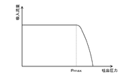
- FIG. 2 is a graph showing the relationship between the discharge pressure and the suction flow rate.
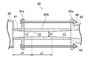
- FIG. 3 is a schematic cross-sectional view of the diffuser to which the first attachment is attached.
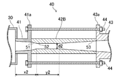
- FIG. 4 is a schematic cross-sectional view of the diffuser to which the second attachment is attached.
- the ejector 10 is a steam ejector that sucks low-pressure steam (second fluid) by ejecting high-pressure steam (first fluid), and mixes and discharges these steam. That is, in the ejector 10, the high-pressure steam is the driving fluid, and the low-pressure steam is the suction fluid.
- the ejector 10 includes a nozzle 20, a suction chamber 30, and a diffuser 40.
- the nozzle 20 is connected to an inflow pipe 91 connected to a supply source of high-pressure steam.
- the nozzle 20 ejects the supplied high-pressure steam.
- the tip of the nozzle 20 is accommodated in the suction chamber 30.
- the suction chamber 30 is provided with a suction port 31 for low-pressure steam.
- the low pressure steam is sucked from the suction port 31 into the suction chamber 30 by the negative pressure (pressure drop) generated when the high pressure steam is ejected from the nozzle 20. That is, in the suction chamber 30, a suction force for sucking the low-pressure steam is generated by the negative pressure generated by the jet pump effect of the high-pressure steam.
- the suction port 31 is connected to a suction pipe 92 connected to the supply source of the low-pressure steam.
- the diffuser 40 is connected to the suction chamber 30.
- the diffuser 40 mixes and discharges the high-pressure steam ejected into the suction chamber 30 and the low-pressure steam sucked into the suction chamber 30.
- An outflow pipe 93 connected to the supply destination of the mixed steam is connected to the downstream end of the diffuser 40.
- the diffuser 40 has a divided structure including an upstream portion 41, an attachment 42 and a downstream portion 43.
- the upstream end of the upstream portion 41 is connected to the suction chamber 30.
- a flange 41 a is provided at the downstream end of the upstream portion 41.
- a first flange 43 a is provided at the upstream end of the downstream portion 43, and a second flange 43 b is provided at the downstream end of the downstream portion 43.
- the downstream part 43 is connected to the outflow pipe 93 via the second flange 43b.
- the attachment 42 is sandwiched between the upstream portion 41 and the downstream portion 43.
- the attachment 42 is held by the upstream portion 41 and the downstream portion 43 by tightening the flange 41 a of the upstream portion 41 and the first flange 43 a of the downstream portion 43 with a bolt 44. That is, the attachment 42 can be replaced by loosening the fastening of the bolt 44.
- the attachment 42 is an example of a changing unit.
- the diffuser 40 is formed with an outlet channel 50 for high-pressure steam and low-pressure steam that communicates with the suction chamber 30.
- the outlet channel 50 includes a reduced channel 51, a parallel channel 52, and an enlarged channel 53 that are sequentially connected from the upstream side.
- the cross section of the outlet channel 50 is substantially circular. The diffuser 40 decelerates and pressurizes the mixed steam when the mixed steam flows through the enlarged flow path 53.
- the upstream end of the reduced flow path 51 is open to the suction chamber 30.
- the upstream end of the reduced flow path 51 faces the downstream end of the nozzle 20 in the suction chamber 30.
- the cross-sectional area, that is, the inner diameter of the reduced flow channel 51 gradually decreases toward the downstream side.
- a parallel flow path 52 is connected to the downstream end of the reduction flow path 51.
- the parallel flow path 52 is a flow path having a constant cross-sectional area, that is, an inner diameter.
- the parallel flow path 52 is a portion having the smallest inner diameter in the outlet flow path 50 and constitutes a so-called throat portion.
- An enlarged channel 53 is connected to the downstream end of the parallel channel 52.
- the cross-sectional area of the enlarged flow path 53 that is, the inner diameter gradually increases toward the downstream side.
- the reduced flow path 51 is formed from the upstream portion 41 to the attachment 42.
- the parallel flow path 52 is formed in the attachment 42.
- the enlarged flow path 53 is formed from the attachment 42 to the downstream portion 43. That is, at least the upstream end portion of the reduced flow channel 51 is formed in the upstream portion 41.
- the attachment 42 is formed with at least the downstream end of the reduced flow channel 51, the parallel flow channel 52, and at least the upstream end of the enlarged flow channel 53. At the downstream portion 43, at least the downstream end portion of the enlarged flow path 53 is formed.
- the high-pressure steam flowing through the inflow pipe 91 is ejected from the nozzle 20 into the suction chamber 30, and the low-pressure steam is ejected from the suction port 31 into the suction chamber 30 by the ejection of the high-pressure steam. Sucked.
- the high pressure steam and low pressure steam in the suction chamber 30 are mixed and discharged from the diffuser 40.
- the steam discharged from the diffuser 40 is supplied to the downstream apparatus.
- the flow velocity of the mixed steam is approximately the speed of sound in the parallel flow path 52 of the diffuser 40. Thereafter, the mixed steam is decelerated and pressurized when flowing through the enlarged flow path 53.
- the discharge pressure of the ejector 10 may increase depending on the operating conditions and specifications of the steam supply destination device.
- this discharge pressure is referred to as “maximum discharge pressure” that can secure the suction flow rate of the low-pressure steam.
- Pmax the maximum discharge pressure
- the suction pressure starts to rise.
- the flow velocity in the parallel flow path 52 becomes lower than the sound velocity and becomes a non-critical state, and the suction pressure rises to a value almost equal to the discharge pressure. That is, when the discharge pressure exceeds the maximum discharge pressure Pmax, the suction flow rate of the low-pressure steam decreases rapidly.
- the maximum discharge pressure Pmax can be changed according to the specifications of the outlet channel 50, that is, the dimensions. For example, it is conceivable to increase the maximum discharge pressure Pmax by reducing the inner diameter D of the parallel flow path 52. When the inner diameter D of the parallel flow path 52 decreases, the flow rate of the mixed steam in the parallel flow path 52 increases, so that a critical state of pressure in the parallel flow path 52 is easily ensured.
- changing only the inner diameter D of the parallel flow path 52 may not only increase the maximum discharge pressure Pmax but also may not maintain the performance of the ejector 10. For example, even if the maximum discharge pressure Pmax can be increased, the suction flow rate of low-pressure steam may be significantly reduced, or conversely, the maximum discharge pressure Pmax may be reduced. That is, various dimensions of the outlet channel 50 are related to the performance of the ejector 1, and it is necessary to change dimensions other than the inner diameter D of the parallel channel 52.
- the dimensions of the reduced flow path 51 and the parallel flow path 52 are set so as to satisfy the following expressions (1) and (2). That is, even when the dimensions of the reduced flow path 51 and the parallel flow path 52 are changed, the expressions (1) and (2) are satisfied before and after the change.
- X A ⁇ D (1)
- Y B ⁇ D (2)
- X is the length of the reduced flow path 51
- Y is the length of the parallel flow path 52
- A is a constant
- B is a constant
- D is the inner diameter of the parallel flow path 52.
- the length X of the reduced flow path 51 and the length Y of the parallel flow path 52 change in proportion to the inner diameter D of the parallel flow path 52. Further, even if the dimensions of the reduced flow path 51 and the parallel flow path 52 are changed, the ratio (X / D) of the length X of the reduced flow path 51 to the inner diameter D of the parallel flow path 52 is constant at A, The ratio (Y / D) of the length Y of the parallel flow path 52 to the inner diameter D of the parallel flow path 52 is constant at B. As a result, the ratio (Y / X) of the length Y of the parallel flow path 52 to the length X of the reduced flow path 51 is constant at B / A.
- X / D is substantially equal before and after the change
- Y / D is substantially equal before and after the change
- the length of the enlarged flow path 53 is set to a value that does not affect the performance of the ejector 10 even if the lengths of the reduced flow path 51 and the parallel flow path 52 change.
- the diffuser 40 is configured such that the dimensions of the outlet channel 50 can be changed by replacing the attachment 42. Thereby, the dimension of the outlet channel 50 can be easily changed without replacing the entire ejector 10.
- FIG. 3 is a schematic cross-sectional view of the diffuser 40 to which the first attachment 42A is attached
- FIG. 4 is a schematic cross-sectional view of the diffuser 40 to which the second attachment 42B is attached.
- the first attachment 42A has a parallel flow path 52 having an inner diameter D of d1.
- the length x1 of the reduced flow path 51 is A ⁇ d1
- the length y1 of the parallel flow path 52 is B ⁇ d1.
- the second attachment 42B has a parallel flow path 52 having an inner diameter D of d2.
- the length x2 of the reduced flow path 51 in the second attachment 42B is A ⁇ d2
- the length y2 of the parallel flow path 52 is B ⁇ d2.
- the inner diameter d2 of the parallel flow path 52 of the second attachment 42B is smaller than the inner diameter d1 of the parallel flow path 52 of the first attachment 42A. Therefore, the reduced flow path 51 and the parallel flow path 52 of the second attachment 42B are shorter than those of the first attachment 42A.
- the reduced flow path 51 and the parallel flow path 52 are shortened, so that the enlarged flow path 53 included in the second attachment 42B.
- decrease flow path 51 is the 2nd part formed in the upstream part 41, and 2nd. It differs from the part formed in the attachment 42B.
- the angle of the inner peripheral wall with respect to the axis of the enlarged flow path 53 is the same as the part formed in the second attachment 42B. It differs from the portion formed in the downstream portion 43.
- the maximum discharge pressure Pmax of the diffuser 40 in which the second attachment 42B is incorporated is the first attachment. It becomes higher than the case where 42A is incorporated.
- the relationship of the expressions (1) and (2) is maintained before and after the change of the dimension of the outlet channel 50. That is, x2 / d2 is substantially equal to x1 / d1, and y2 / d2 is substantially equal to y1 / d2.
- the maximum discharge pressure Pmax can be increased while maintaining the performance of the ejector 1.
- the maximum discharge pressure Pmax can be increased while ensuring a sufficient suction flow rate.
- the method for manufacturing the ejector 1 includes a setting step for setting the dimension of the outlet channel 50 and a preparation step for preparing the diffuser 40 having the dimension set in the setting step.
- the length X of the reduced flow path 51 and the length Y and the inner diameter D of the parallel flow path 52 are set.
- the length X of the reduced flow path 51 and the length Y and the inner diameter D of the parallel flow path 52 are set so as to satisfy the expressions (1) and (2).
- the inner diameter D of the parallel flow path 52 is set, and the length X of the reduction flow path 51 and the length Y of the parallel flow path 52 are set accordingly.
- the length of the enlarged flow path 53 is set.
- the length of the enlarged flow path 53 is inevitably determined from the length X of the reduced flow path 51 and the length Y of the parallel flow path 52.
- the diffuser 40 that realizes the length X of the reduced flow path 51 set in the setting step and the length Y and the inner diameter D of the parallel flow path 52 is prepared.
- the attachment 42 for realizing the length X of the reduced flow path 51 set in the setting step, and the length Y and the inner diameter D of the parallel flow path 52 are provided.
- the inner diameter D of the parallel flow path 52 is different, and a plurality of attachments 42 having the reduced flow path 51 and the parallel flow path 52 satisfying the expressions (1) and (2). Has been prepared.
- An attachment 42 suitable for the operating status and specifications of the apparatus to which the steam is supplied is selected.
- the manufacturing method of the ejector 1 further includes an assembly step.
- the nozzle 20, the suction chamber 30, and the diffuser 40 are assembled.
- the upstream portion 41 of the nozzle 20 and the diffuser 40 is attached to the suction chamber 30.
- the attachment 42 and the downstream portion 43 are attached to the upstream portion 41 in a state where the attachment 42 is sandwiched between the upstream portion 41 and the downstream portion 43.
- the ejector 10 includes the nozzle 20 that ejects the high-pressure steam (first fluid) and the low-pressure steam (second fluid) due to the negative pressure that is generated when the nozzle 20 is accommodated and the high-pressure steam is ejected from the nozzle 20.
- the reduced flow path 51 whose cross-sectional area decreases toward the downstream side, and is connected to the downstream end of the reduced flow path 51, connected to the parallel flow path 52 having a constant cross-sectional area, and the downstream end of the parallel flow path 52, downstream
- the diffuser 40 further includes an attachment 42 (changing portion) for changing the size of the outlet flow channel 50, and the attachment 42 is a reduced flow channel.
- the length X of the reduced flow path 51 and the length Y and the inner diameter D of the parallel flow path 52 are changed by the attachment 42.
- the maximum discharge pressure Pmax of the ejector 10 can be changed.
- the length X of the reduced flow path 51 and the length Y and the inner diameter D of the parallel flow path 52 satisfy the expressions (1) and (2).
- the performance of the ejector 10 is affected by various dimensions of the outlet channel 50.
- the deterioration of the performance of the ejector 10 is reduced by setting the length X of the reduced flow path 51 and the length Y and the inner diameter D of the parallel flow path 52 so as to satisfy at least the expressions (1) and (2). be able to. That is, the maximum discharge pressure Pmax of the ejector 10 can be changed while reducing the deterioration of the performance of the ejector 10.
- a part of the diffuser 40 is configured by a replaceable attachment 42, and the attachment 42 is at least a downstream end portion of the reduction flow path 51, a parallel flow path 52, and at least an upstream end of the expansion flow path 53.
- the dimensions of the outlet channel 50 are changed while satisfying the expressions (1) and (2) by replacing the attachment 42.
- the diffuser 40 is configured such that the attachment 42 can be replaced.
- the plurality of attachments 42 are formed with reduced flow paths 51 and parallel flow paths 52 having different dimensions.
- the reduced flow path 51 and the parallel flow path 52 when the one attachment 42 is incorporated, and the reduced flow path 51 and the parallel flow path 52 when the other attachment 42 is incorporated are also expressed by the equations (1) and (2). Satisfies.
- the maximum discharge pressure Pmax of the ejector 10 can be changed by replacing the attachment 42 without replacing the entire diffuser 40, and the deterioration of the performance of the ejector 10 at that time can be reduced. Can do.
- the manufacturing method of the ejector 10 includes a setting step for setting the dimension of the outlet flow channel 50 and a preparation step for preparing the diffuser 40 having the dimension of the outlet flow channel 50 set in the setting step.
- the length X of the reduced flow path 51 and the length Y and the inner diameter D of the parallel flow path 52 are set so as to satisfy the expressions (1) and (2).
- the preparation step by replacing the attachment 42 of the diffuser 40 including the exchangeable attachment 42, the length X of the reduced flow path 51 set in the setting step, and the length Y of the parallel flow path 52 and A diffuser 40 having an inner diameter D is prepared.
- the dimensions of the reduced flow path 51 and the parallel flow path 52 of the diffuser 40 are changed by replacing the attachment 42. Therefore, the dimensions of the reduced flow path 51 and the parallel flow path 52 can be changed without changing the entire diffuser 40.
- the setting method of the exit flow path of the diffuser 40 sets the length X of the reduction
- the diffuser 40 has a three-part structure, but may have two or four or more parts.
- the fixing method of the attachment 42 is not limited to the method by sandwiching the upstream portion 41 and the downstream portion 42. Any fixing method can be employed as long as the attachment 42 can be fixed.
- the configuration for changing the dimension of the outlet channel 50 is not limited to that by the attachment 42.
- the diffuser may have a deformation mechanism capable of deforming the inner diameter.
- the deformation mechanism partitions the outlet flow channel 50 and has a flexible tubular wall portion, and a plurality of pressing members that are arranged circumferentially on the outer periphery of the wall portion and press the wall portion radially inward (
- a bolt may be included.
- a plurality of sets of pressing members are provided at different positions in the axial direction of the wall portion, with a plurality of pressing members arranged in the circumferential direction of the wall portion as one set. That is, the length Y and the axial position of the parallel flow path 52 can be changed depending on which position in the axial direction is pressed by the pressing member. Changing the axial position of the parallel flow path 52 changes the length X of the reduced flow path 51. That is, the length X of the reduced flow path 51 and the length Y of the parallel flow path 52 can also be changed. In addition to such a configuration, any configuration that can change the dimensions of the outlet channel 50 can be employed.
- the diffuser 40 has a divided structure including the attachment 42, but is not limited to this.
- the diffuser 40 may be an integral structure.
- each of the plurality of diffusers 40 has an outlet channel 50 having a different size, but the reduced channel 51 and the parallel channel 52 of each outlet channel 50 are expressed by the equations (1) and (2). Meet.
- An appropriate diffuser 40 is selected from these, and incorporated in the ejector 10.
- the diffuser 40 having the length X of the reduced flow path 51 set in the setting step and the length Y and the inner diameter D of the parallel flow path 52 is replaced with a plurality of diffusers 40. Select from among them or create a new one.
- the technique disclosed herein is useful for an ejector, a method for manufacturing the ejector, and a method for setting an outlet flow path of a diffuser used in the ejector.
Landscapes
- Engineering & Computer Science (AREA)
- Physics & Mathematics (AREA)
- Fluid Mechanics (AREA)
- Mechanical Engineering (AREA)
- General Engineering & Computer Science (AREA)
- Jet Pumps And Other Pumps (AREA)
- Nozzles (AREA)
Abstract
Description
Y=B×D ・・・(2)
また、ここに開示されたエゼクタの製造方法は、前記出口流路の寸法を設定する設定ステップと、前記設定ステップで設定された前記出口流路の寸法を有する前記ディフューザを準備する準備ステップとを含み、前記設定ステップでは、前記縮小流路の長さX、並びに、前記平行流路の長さY及び内径Dを定数A,Bを用いて表される前記式(1)、(2)を満たすように設定する。
Y=B×D ・・・(2)
ここで、Xは縮小流路51の長さ、Yは平行流路52の長さ、Aは定数、Bは定数、Dは平行流路52の内径である。
Y=B×D ・・・(2)
ここで、A,Bは、定数である。
Y=B×D ・・・(2)
ここで、A,Bは、定数である。
Y=B×D ・・・(2)
ここで、A,Bは、定数である。
以上のように、本出願において開示する技術の例示として、前記実施形態を説明した。しかしながら、本開示における技術は、これに限定されず、適宜、変更、置き換え、付加、省略などを行った実施の形態にも適用可能である。また、前記実施形態で説明した各構成要素を組み合わせて、新たな実施の形態とすることも可能である。また、添付図面および詳細な説明に記載された構成要素の中には、課題解決のために必須な構成要素だけでなく、前記技術を例示するために、課題解決のためには必須でない構成要素も含まれ得る。そのため、それらの必須ではない構成要素が添付図面や詳細な説明に記載されていることをもって、直ちに、それらの必須ではない構成要素が必須であるとの認定をするべきではない。
20 ノズル
30 吸引室
40 ディフューザ
42 アタッチメント(変更部)
42A 第1アタッチメント(変更部)
42B 第2アタッチメント(変更部)
50 出口流路
51 縮小流路
52 平行流路
53 拡大流路
Claims (5)
- 第1流体を噴出するノズルと、
前記ノズルが収容され、前記ノズルから前記第1流体が噴出することによって生じる負圧により第2流体が吸引される吸引室と、
出口流路を有し、前記吸引室の前記第1流体及び前記第2流体を混合して吐出するディフューザとを備え、
前記出口流路は、下流側に向かって断面積が小さくなる縮小流路と、前記縮小流路の下流端に接続され、断面積が一定の平行流路と、前記平行流路の下流端に接続され、下流側に向かって断面積が大きくなる拡大流路とを含んでおり、
前記ディフューザは、前記出口流路の寸法を変更する変更部をさらに有し、
前記変更部は、前記縮小流路の長さX、並びに、前記平行流路の長さY及び内径Dを定数A,Bを用いて表される下記式(1)、(2)を満たすように変更することを特徴とするエゼクタ。
X=A×D ・・・(1)
Y=B×D ・・・(2) - 請求項1に記載のエゼクタにおいて
前記ディフューザの一部は、交換可能なアタッチメントで構成され、
前記変更部は、前記アタッチメントであり、
前記アタッチメントは、前記縮小流路の少なくとも一部と、前記平行流路と、前記拡大流路の少なくとも一部とを含んでおり、
前記出口流路の寸法は、前記アタッチメントを交換することによって、前記式(1)、(2)を満たしつつ変更されることを特徴とするエゼクタ。 - 第1流体を噴出するノズルと、前記ノズルが収容され、前記ノズルから前記第1流体が噴出することによって生じる負圧により第2流体が吸引される吸引室と、下流側に向かって断面積が小さくなる縮小流路、前記縮小流路の下流端に接続され、断面積が一定の平行流路、及び、前記平行流路の下流端に接続され、下流側に向かって断面積が大きくなる拡大流路を含む出口流路を有し、前記吸引室の前記第1流体及び前記第2流体を混合して吐出するディフューザとを備えたエゼクタの製造方法であって、
前記出口流路の寸法を設定する設定ステップと、
前記設定ステップで設定された前記出口流路の寸法を有する前記ディフューザを準備する準備ステップとを含み、
前記設定ステップでは、前記縮小流路の長さX、並びに、前記平行流路の長さY及び内径Dを定数A,Bを用いて表される下記式(1)、(2)を満たすように設定することを特徴とするエゼクタの製造方法。
X=A×D ・・・(1)
Y=B×D ・・・(2) - 請求項3に記載のエゼクタの製造方法において、
前記準備ステップでは、交換可能なアタッチメントを含むディフューザの前記アタッチメントを交換することによって、前記設定ステップで設定された前記出口流路の寸法を有する前記ディフューザを準備することを特徴とするエゼクタの製造方法。 - 下流側に向かって断面積が小さくなる縮小流路と、前記縮小流路の下流端に接続され、断面積が一定の平行流路と、前記平行流路の下流端に接続され、下流側に向かって断面積が大きくなる拡大流路とを含む出口流路を有し、エゼクタに用いられるディフューザの出口流路の設定方法であって、
前記縮小流路の長さXを、前記平行流路の内径D及び定数Aを用いて表される下記式(1)を満たすように設定するステップと、
前記平行流路の長さYを、前記内径D及び定数Bを用いて表される下記式(2)を満たすように設定するステップとを含むことを特徴とするディフューザの出口流路の設定方法。
X=A×D ・・・(1)
Y=B×D ・・・(2)
Priority Applications (4)
| Application Number | Priority Date | Filing Date | Title |
|---|---|---|---|
| JP2017527833A JP6352544B2 (ja) | 2016-04-01 | 2017-02-15 | エゼクタ、エゼクタの製造方法及びディフューザの出口流路の設定方法 |
| CN201780019768.5A CN108884840B (zh) | 2016-04-01 | 2017-02-15 | 喷射器、喷射器的制造方法以及扩散器的出口流路的设定方法 |
| EP17773766.5A EP3438465B1 (en) | 2016-04-01 | 2017-02-15 | Ejector, ejector production method, and method for setting diffuser outlet flow path |
| US16/146,915 US11131326B2 (en) | 2016-04-01 | 2018-09-28 | Ejector, ejector production method, and method for setting diffuser outlet flow path |
Applications Claiming Priority (2)
| Application Number | Priority Date | Filing Date | Title |
|---|---|---|---|
| JP2016-074552 | 2016-04-01 | ||
| JP2016074552 | 2016-04-01 |
Related Child Applications (1)
| Application Number | Title | Priority Date | Filing Date |
|---|---|---|---|
| US16/146,915 Continuation US11131326B2 (en) | 2016-04-01 | 2018-09-28 | Ejector, ejector production method, and method for setting diffuser outlet flow path |
Publications (1)
| Publication Number | Publication Date |
|---|---|
| WO2017169218A1 true WO2017169218A1 (ja) | 2017-10-05 |
Family
ID=59962953
Family Applications (1)
| Application Number | Title | Priority Date | Filing Date |
|---|---|---|---|
| PCT/JP2017/005468 Ceased WO2017169218A1 (ja) | 2016-04-01 | 2017-02-15 | エゼクタ、エゼクタの製造方法及びディフューザの出口流路の設定方法 |
Country Status (5)
| Country | Link |
|---|---|
| US (1) | US11131326B2 (ja) |
| EP (1) | EP3438465B1 (ja) |
| JP (1) | JP6352544B2 (ja) |
| CN (1) | CN108884840B (ja) |
| WO (1) | WO2017169218A1 (ja) |
Cited By (1)
| Publication number | Priority date | Publication date | Assignee | Title |
|---|---|---|---|---|
| KR20230022970A (ko) * | 2020-06-10 | 2023-02-16 | 로베르트 보쉬 게엠베하 | 기체 매체를 운반 및/또는 제어하기 위한 연료 전지 시스템용 운반 유닛 |
Families Citing this family (3)
| Publication number | Priority date | Publication date | Assignee | Title |
|---|---|---|---|---|
| CN113669305B (zh) * | 2020-05-14 | 2023-06-20 | 中国石油化工股份有限公司 | 一种可更换式引射装置 |
| CN115467862A (zh) * | 2022-10-14 | 2022-12-13 | 国家电投集团氢能科技发展有限公司 | 混合室可调式引射器和燃料电池 |
| CN118988587A (zh) * | 2023-05-22 | 2024-11-22 | 开利公司 | 喷射器以及具有其的制冷系统 |
Citations (2)
| Publication number | Priority date | Publication date | Assignee | Title |
|---|---|---|---|---|
| JPS5779152U (ja) * | 1980-10-29 | 1982-05-15 | ||
| US6877960B1 (en) * | 2002-06-05 | 2005-04-12 | Flodesign, Inc. | Lobed convergent/divergent supersonic nozzle ejector system |
Family Cites Families (14)
| Publication number | Priority date | Publication date | Assignee | Title |
|---|---|---|---|---|
| US2888191A (en) * | 1954-05-03 | 1959-05-26 | Rheem Mfg Co | Jet pump |
| US3448691A (en) * | 1967-07-03 | 1969-06-10 | David M Frazier | Energy controller |
| GB1420215A (en) * | 1972-03-09 | 1976-01-07 | British Gas Corp | Jet boosters |
| FR2239142A5 (en) * | 1973-07-27 | 1975-02-21 | Utilisation Ration Gaz | Hot gas flow generator - has burner delivering high-speed gas into coaxial venturi |
| US4595344A (en) * | 1982-09-30 | 1986-06-17 | Briley Patrick B | Ejector and method of controlling same |
| FR2554874B1 (fr) * | 1983-11-10 | 1988-04-15 | Bertin & Cie | Ejecteur-melangeur a effet de trompe a section variable et application |
| US4898517A (en) * | 1988-10-21 | 1990-02-06 | Eriksen Olof A | Steam/air ejector for generating a vacuum |
| JP2000356305A (ja) | 1999-06-15 | 2000-12-26 | Tlv Co Ltd | 復水回収装置 |
| KR100381194B1 (ko) * | 2000-10-10 | 2003-04-26 | 엘지전자 주식회사 | 용량 가변형 이젝터 |
| SG157325A1 (en) * | 2008-05-29 | 2009-12-29 | Denso Corp | Ejector and manufacturing method thereof |
| ES2594349T3 (es) * | 2010-11-30 | 2016-12-19 | Carrier Corporation | Eyector |
| CN104801435A (zh) * | 2014-01-23 | 2015-07-29 | 刘友宏 | 菊花型喷嘴射水抽气器和喷射式混合器 |
| GB2524499B (en) * | 2014-03-24 | 2020-02-12 | Caltec Ltd | Jet pump |
| KR102303676B1 (ko) * | 2014-12-30 | 2021-09-23 | 삼성전자주식회사 | 이젝터 및 이를 갖는 냉동장치 |
-
2017
- 2017-02-15 CN CN201780019768.5A patent/CN108884840B/zh active Active
- 2017-02-15 WO PCT/JP2017/005468 patent/WO2017169218A1/ja not_active Ceased
- 2017-02-15 EP EP17773766.5A patent/EP3438465B1/en active Active
- 2017-02-15 JP JP2017527833A patent/JP6352544B2/ja active Active
-
2018
- 2018-09-28 US US16/146,915 patent/US11131326B2/en active Active
Patent Citations (2)
| Publication number | Priority date | Publication date | Assignee | Title |
|---|---|---|---|---|
| JPS5779152U (ja) * | 1980-10-29 | 1982-05-15 | ||
| US6877960B1 (en) * | 2002-06-05 | 2005-04-12 | Flodesign, Inc. | Lobed convergent/divergent supersonic nozzle ejector system |
Cited By (4)
| Publication number | Priority date | Publication date | Assignee | Title |
|---|---|---|---|---|
| KR20230022970A (ko) * | 2020-06-10 | 2023-02-16 | 로베르트 보쉬 게엠베하 | 기체 매체를 운반 및/또는 제어하기 위한 연료 전지 시스템용 운반 유닛 |
| JP2023528431A (ja) * | 2020-06-10 | 2023-07-04 | ロベルト・ボッシュ・ゲゼルシャフト・ミト・ベシュレンクテル・ハフツング | ガス状の媒体を供給および/または制御するための燃料電池システム用のフィードユニット |
| JP7585355B2 (ja) | 2020-06-10 | 2024-11-18 | ロベルト・ボッシュ・ゲゼルシャフト・ミト・ベシュレンクテル・ハフツング | ガス状の媒体を供給および/または制御するための燃料電池システム用のフィードユニット |
| KR102965505B1 (ko) | 2020-06-10 | 2026-05-18 | 로베르트 보쉬 게엠베하 | 기체 매체를 운반 및/또는 제어하기 위한 연료 전지 시스템용 운반 유닛 |
Also Published As
| Publication number | Publication date |
|---|---|
| US11131326B2 (en) | 2021-09-28 |
| EP3438465A4 (en) | 2019-03-27 |
| CN108884840A (zh) | 2018-11-23 |
| EP3438465A1 (en) | 2019-02-06 |
| JPWO2017169218A1 (ja) | 2018-04-05 |
| JP6352544B2 (ja) | 2018-07-04 |
| US20190032678A1 (en) | 2019-01-31 |
| CN108884840B (zh) | 2020-03-31 |
| EP3438465B1 (en) | 2020-04-01 |
Similar Documents
| Publication | Publication Date | Title |
|---|---|---|
| JP6352544B2 (ja) | エゼクタ、エゼクタの製造方法及びディフューザの出口流路の設定方法 | |
| JP6821383B2 (ja) | 高真空イジェクタ | |
| CN106568220B (zh) | 使用旋流的喷射器 | |
| CN104847708B (zh) | 超声速引射器 | |
| CN105570202B (zh) | 一种内壁结构可调节的喷射器 | |
| CN104929990B (zh) | 引射器喷管 | |
| JP6352543B2 (ja) | エゼクタ、エゼクタの製造方法及びディフューザの出口流路の設定方法 | |
| JP2001295800A (ja) | エゼクタ式真空発生器 | |
| US9295952B2 (en) | Venturi tube fluid mixer with at least two inflection points in the divergent section | |
| CN113614386A (zh) | 射流泵 | |
| JP4802786B2 (ja) | 遠心形ターボ機械 | |
| JP6144854B1 (ja) | エゼクタ | |
| CN222342199U (zh) | 多级混合装置 | |
| JP2017155621A (ja) | エジェクタ | |
| JP5630029B2 (ja) | ノズル及び分散装置 | |
| JP2018048578A (ja) | エゼクタ及び取付構造 | |
| JP5428962B2 (ja) | 軸流圧縮機及びガスタービンエンジン | |
| JP7490945B2 (ja) | エジェクタ | |
| RU72736U1 (ru) | Эжектор | |
| CN201728166U (zh) | 一种低噪声耐低温亚音速喷射器 | |
| RU2354856C1 (ru) | Эжектор | |
| JP2023096418A (ja) | 渦巻ポンプ | |
| CN121131360A (zh) | 一种管道清洗系统及其喷射组件 |
Legal Events
| Date | Code | Title | Description |
|---|---|---|---|
| ENP | Entry into the national phase |
Ref document number: 2017527833 Country of ref document: JP Kind code of ref document: A |
|
| NENP | Non-entry into the national phase |
Ref country code: DE |
|
| WWE | Wipo information: entry into national phase |
Ref document number: 2017773766 Country of ref document: EP |
|
| ENP | Entry into the national phase |
Ref document number: 2017773766 Country of ref document: EP Effective date: 20181102 |
|
| 121 | Ep: the epo has been informed by wipo that ep was designated in this application |
Ref document number: 17773766 Country of ref document: EP Kind code of ref document: A1 |