WO2017169517A1 - 過給機、2ステージターボシステム、および2ステージターボシステムの制御方法 - Google Patents
過給機、2ステージターボシステム、および2ステージターボシステムの制御方法 Download PDFInfo
- Publication number
- WO2017169517A1 WO2017169517A1 PCT/JP2017/008573 JP2017008573W WO2017169517A1 WO 2017169517 A1 WO2017169517 A1 WO 2017169517A1 JP 2017008573 W JP2017008573 W JP 2017008573W WO 2017169517 A1 WO2017169517 A1 WO 2017169517A1
- Authority
- WO
- WIPO (PCT)
- Prior art keywords
- passage
- low
- pressure stage
- scroll
- exhaust gas
- Prior art date
- Legal status (The legal status is an assumption and is not a legal conclusion. Google has not performed a legal analysis and makes no representation as to the accuracy of the status listed.)
- Ceased
Links
Images






Classifications
-
- F—MECHANICAL ENGINEERING; LIGHTING; HEATING; WEAPONS; BLASTING
- F02—COMBUSTION ENGINES; HOT-GAS OR COMBUSTION-PRODUCT ENGINE PLANTS
- F02B—INTERNAL-COMBUSTION PISTON ENGINES; COMBUSTION ENGINES IN GENERAL
- F02B37/00—Engines characterised by provision of pumps driven at least for part of the time by exhaust
- F02B37/02—Gas passages between engine outlet and pump drive, e.g. reservoirs
- F02B37/025—Multiple scrolls or multiple gas passages guiding the gas to the pump drive
-
- F—MECHANICAL ENGINEERING; LIGHTING; HEATING; WEAPONS; BLASTING
- F02—COMBUSTION ENGINES; HOT-GAS OR COMBUSTION-PRODUCT ENGINE PLANTS
- F02B—INTERNAL-COMBUSTION PISTON ENGINES; COMBUSTION ENGINES IN GENERAL
- F02B37/00—Engines characterised by provision of pumps driven at least for part of the time by exhaust
- F02B37/004—Engines characterised by provision of pumps driven at least for part of the time by exhaust with exhaust drives arranged in series
-
- F—MECHANICAL ENGINEERING; LIGHTING; HEATING; WEAPONS; BLASTING
- F02—COMBUSTION ENGINES; HOT-GAS OR COMBUSTION-PRODUCT ENGINE PLANTS
- F02B—INTERNAL-COMBUSTION PISTON ENGINES; COMBUSTION ENGINES IN GENERAL
- F02B37/00—Engines characterised by provision of pumps driven at least for part of the time by exhaust
- F02B37/013—Engines characterised by provision of pumps driven at least for part of the time by exhaust with exhaust-driven pumps arranged in series
-
- F—MECHANICAL ENGINEERING; LIGHTING; HEATING; WEAPONS; BLASTING
- F02—COMBUSTION ENGINES; HOT-GAS OR COMBUSTION-PRODUCT ENGINE PLANTS
- F02B—INTERNAL-COMBUSTION PISTON ENGINES; COMBUSTION ENGINES IN GENERAL
- F02B37/00—Engines characterised by provision of pumps driven at least for part of the time by exhaust
- F02B37/02—Gas passages between engine outlet and pump drive, e.g. reservoirs
-
- F—MECHANICAL ENGINEERING; LIGHTING; HEATING; WEAPONS; BLASTING
- F02—COMBUSTION ENGINES; HOT-GAS OR COMBUSTION-PRODUCT ENGINE PLANTS
- F02B—INTERNAL-COMBUSTION PISTON ENGINES; COMBUSTION ENGINES IN GENERAL
- F02B37/00—Engines characterised by provision of pumps driven at least for part of the time by exhaust
- F02B37/12—Control of the pumps
- F02B37/18—Control of the pumps by bypassing exhaust from the inlet to the outlet of turbine or to the atmosphere
-
- F—MECHANICAL ENGINEERING; LIGHTING; HEATING; WEAPONS; BLASTING
- F02—COMBUSTION ENGINES; HOT-GAS OR COMBUSTION-PRODUCT ENGINE PLANTS
- F02B—INTERNAL-COMBUSTION PISTON ENGINES; COMBUSTION ENGINES IN GENERAL
- F02B37/00—Engines characterised by provision of pumps driven at least for part of the time by exhaust
- F02B37/12—Control of the pumps
- F02B37/18—Control of the pumps by bypassing exhaust from the inlet to the outlet of turbine or to the atmosphere
- F02B37/183—Arrangements of bypass valves or actuators therefor
-
- F—MECHANICAL ENGINEERING; LIGHTING; HEATING; WEAPONS; BLASTING
- F02—COMBUSTION ENGINES; HOT-GAS OR COMBUSTION-PRODUCT ENGINE PLANTS
- F02B—INTERNAL-COMBUSTION PISTON ENGINES; COMBUSTION ENGINES IN GENERAL
- F02B37/00—Engines characterised by provision of pumps driven at least for part of the time by exhaust
- F02B37/12—Control of the pumps
- F02B37/22—Control of the pumps by varying cross-section of exhaust passages or air passages, e.g. by throttling turbine inlets or outlets or by varying effective number of guide conduits
-
- F—MECHANICAL ENGINEERING; LIGHTING; HEATING; WEAPONS; BLASTING
- F01—MACHINES OR ENGINES IN GENERAL; ENGINE PLANTS IN GENERAL; STEAM ENGINES
- F01D—NON-POSITIVE DISPLACEMENT MACHINES OR ENGINES, e.g. STEAM TURBINES
- F01D9/00—Stators
- F01D9/02—Nozzles; Nozzle boxes; Stator blades; Guide conduits, e.g. individual nozzles
- F01D9/026—Scrolls for radial machines or engines
-
- Y—GENERAL TAGGING OF NEW TECHNOLOGICAL DEVELOPMENTS; GENERAL TAGGING OF CROSS-SECTIONAL TECHNOLOGIES SPANNING OVER SEVERAL SECTIONS OF THE IPC; TECHNICAL SUBJECTS COVERED BY FORMER USPC CROSS-REFERENCE ART COLLECTIONS [XRACs] AND DIGESTS
- Y02—TECHNOLOGIES OR APPLICATIONS FOR MITIGATION OR ADAPTATION AGAINST CLIMATE CHANGE
- Y02T—CLIMATE CHANGE MITIGATION TECHNOLOGIES RELATED TO TRANSPORTATION
- Y02T10/00—Road transport of goods or passengers
- Y02T10/10—Internal combustion engine [ICE] based vehicles
- Y02T10/12—Improving ICE efficiencies
Definitions
- the present disclosure relates to a supercharger, a two-stage turbo system, and a control method for the two-stage turbo system.
- a two-stage turbo system is known as a supercharging system applicable to an engine such as a diesel engine.
- the two-stage turbo system can be applied to existing diesel engines without significant improvement. It is a supercharging system that achieves both high torque and low output at a low speed and has excellent response (transient response). Promising. More specifically, in the two-stage turbo system, the openings of various valves installed in the exhaust passage are arranged in series by two turbochargers (turbo), a high-pressure turbocharger and a low-pressure turbocharger. This is a supercharging system capable of switching the supercharging stage through switching of the flow path of the exhaust passage by control.
- the exhaust gas has a small flow rate when the engine is running at a low speed, and the exhaust passage has a flow path so that two-stage supercharging is performed by flowing the exhaust gas in the order of the high-pressure supercharger and the low-pressure supercharger. Can be switched.
- the above two-stage supercharging is performed even at medium engine speed, but the exhaust passage is switched so that a part of the exhaust gas flows directly to the low-pressure supercharger without passing through the high-pressure supercharger. Is done.
- the flow path of the exhaust passage is switched so that one stage supercharging is performed by directly flowing all of the exhaust gas having a large flow rate to the low pressure supercharger.
- a small turbocharger is attached to the high-pressure stage side of the two-stage turbo system, and a large supercharger is attached to the low-pressure stage side.
- the operating range of the compressor is expanded by utilizing the range and the range on the large flow rate side of the low-pressure turbocharger.
- the turbine of the large-sized low-pressure turbocharger is heavier than a small one, and the rotational speed of the turbine is difficult to increase at a low engine speed. That is, the response performance of the turbine of the low-pressure stage turbocharger is inferior when the engine speed is low, so that the supercharging pressure required when the engine is low-speed is mainly provided by the high-pressure stage turbocharger.
- Patent Documents 1 and 2 a method has been proposed for improving the response of the low-pressure supercharger at a low engine speed while maintaining the flow rate range of the low-pressure supercharger.
- Patent Document 1 proposes that the low-pressure supercharger be a VG turbocharger.
- the VG turbocharger has a variable nozzle vane mechanism (flow rate variable mechanism) on the turbine side, and the response can be improved by narrowing the nozzle opening of the variable nozzle when the engine is running at a low speed.
- Patent Document 2 proposes to apply a twin scroll to the scroll portion of the low-pressure supercharger.
- the twin scroll the scroll portion formed along the circumferential direction of the rotating shaft of the turbine has a structure in which two passages are arranged in the axial direction of the rotating shaft.
- the turbine can be driven without the exhaust gas pressure being reduced.
- VFT turbine as a turbine having a simple structure and a variable flow rate mechanism
- Patent Document 3 The turbine divides the scroll portion in a radial direction by a partition wall into an inner peripheral scroll passage and an outer peripheral scroll passage, a communication hole (throat) communicating between the scroll passages, and an inner peripheral scroll passage or
- a switching valve that switches whether the exhaust gas flows into both scroll passages is provided, and the passage is switched by the switching valve according to the flow rate of the exhaust gas.
- the switching valve is operated to cause the exhaust gas to flow only into the inner peripheral scroll passage, thereby giving rotational torque to the turbine rotor and efficiently rotating the turbine rotor. be able to.
- the switching valve is operated to cause the exhaust gas to flow into the outer scroll passage, and the rotational torque applied to the turbine rotor is reduced by reducing the exhaust gas flow velocity, and the turbine rotor rotates more than necessary. This can also be prevented.
- the VG turbo of Patent Document 1 requires a complicated link mechanism for opening and closing the nozzle vanes, and there is a problem that the structure is complicated.
- the U / C0 characteristic (see FIG. 4 to be described later) of the turbocharger adopting the twin scroll of Patent Document 2 is similar to the characteristic of the supercharger adopting the single scroll, and the response at the low speed of the engine is greatly increased. Such improvement is unlikely.
- the U / C0 characteristic is a characteristic representing the relationship between the turbine operating speed ratio (U / C0) and the turbine efficiency, where U is the peripheral speed of the turbine T, C0 is the turbine inlet / outlet pressure ratio, and the inlet The theoretical speed is defined by the temperature.
- the U / C0 characteristics of the VFT turbine are in the region where the turbine operating speed ratio (U / C0) is small (low speed ratio side). Since the turbine efficiency of the engine is not high, a significant improvement in response cannot be expected as with the twin scroll.
- At least one embodiment of the present invention provides a supercharger with improved supercharging response while generating a necessary supercharging pressure over a wide operating range of the engine.
- An object is to provide a two-stage turbo system provided.
- a turbocharger is: A turbocharger provided with a scroll portion for introducing exhaust gas into a nozzle passage of a turbine installed in an exhaust passage of an engine,
- the scroll portion has at least two scroll passages, a first scroll passage and a second scroll passage, and a first range of the nozzle flow path into which the exhaust gas flowing through the first scroll passage is introduced;
- the second range of the nozzle flow path into which the exhaust gas flowing through the second scroll passage is introduced is configured not to overlap in the circumferential direction of the nozzle flow path,
- the first scroll passage is A partition wall provided along a flow direction of the exhaust gas in a predetermined range in the first scroll passage, wherein the first scroll passage is arranged on an inner peripheral side of the outer peripheral scroll passage and the outer peripheral scroll passage.
- a partition wall having a communication hole that communicates with the outer peripheral side scroll passage and the inner peripheral side scroll passage;
- a flow rate control valve provided on the upstream side of the partition wall for adjusting the flow rate of the exhaust gas flowing through the outer peripheral scroll passage and the inner peripheral scroll passage.
- the scroll portion of the turbocharger turbine includes at least a first scroll passage and a second scroll passage.
- the first scroll passage is configured (formed) with an outer peripheral scroll passage and an inner peripheral scroll passage, and the flow rates of the two passages can be adjusted.
- each of the first scroll passage and the second scroll passage is configured to partially introduce exhaust gas from different directions with respect to the nozzle flow path formed around the turbine wheel.
- the scroll portion of the turbocharger turbine has a nozzle flow for introducing exhaust gas by flowing exhaust gas exhausted from the engine only in a part of the plurality of scroll passages (for example, the first scroll passage).
- the range of the road can be limited to a part thereof.
- each of the plurality of scroll passages is configured not to overlap in the circumferential direction of the nozzle flow path, the highest point of the turbine efficiency in the U / C0 characteristic is set to the low speed ratio side as compared with the twin scroll and the VFT turbine. Can be shifted. That is, the turbine efficiency on the low speed ratio side can be increased. For this reason, when the flow rate of the exhaust gas is low (low speed ratio side) such as when the engine is running at low speed, the supercharger can be driven to rotate more efficiently. Therefore, by adopting the scroll portion having such a feature for the turbine, the turbine can be driven more quickly and efficiently, and the response of supercharging (supercharging effect) can be improved.
- the flow rate control valve is configured such that when the flow rate control valve is in a fully closed state, the entire amount of the exhaust gas flowing into the first scroll passage flows through the inner peripheral side scroll passage, and the flow rate control valve is opened. When in the state, the exhaust gas flowing into the first scroll passage is configured to flow through both the inner scroll passage and the outer scroll passage.
- the flow path of the exhaust gas can be switched to only the inner peripheral scroll passage or both scroll passages depending on the state of the flow control valve. Thereby, the rotational torque of the turbine can be adjusted.
- a two-stage turbo system according to at least one embodiment of the present invention, A high-pressure turbocharger having a high-pressure turbine installed in the exhaust passage of the engine; The supercharger according to (1) or (2), wherein the low pressure stage is larger than the high pressure stage supercharger, and has a low pressure stage turbine installed downstream of the high pressure stage turbine in the exhaust passage. A supercharger.
- the supercharger of (1) or (2) is used for a low-pressure supercharger of a two-stage turbo system.
- the large low-pressure turbine of the two-stage turbo system can be driven more quickly and efficiently, and the supercharging response can be improved.
- the exhaust passage is A high-pressure stage introduction passage connecting the engine and an inlet of the high-pressure stage turbine; A first low-pressure stage introduction passage connecting the outlet side of the high-pressure stage turbine and the first scroll passage of the low-pressure stage turbine; A second low-pressure stage introduction passage that bypasses the high-pressure turbine and connects the engine and the second scroll passage of the low-pressure turbine.
- the exhaust gas that has passed through the high-pressure stage turbine is introduced into the first scroll passage of the low-pressure stage turbine, and the high-pressure stage turbine is passed through the second scroll passage. It is possible to introduce the exhaust gas directly into the low-pressure stage turbine without doing so.
- supercharging is performed using a high-pressure supercharger in order to improve the supercharging response when the rotational speed of the engine is equal to or lower than the middle speed range.
- the flow rate of the exhaust gas after driving the high-pressure turbine can be increased when it is introduced into the nozzle flow path.
- the large low-pressure stage turbine of the stage turbo system can be rotated more quickly and efficiently.
- the flow rate of exhaust gas is small, such as when the engine speed is on the low rotation side (very low rotation region) of the low rotation region, the exhaust gas is caused to flow only into the inner scroll passage by the flow control valve.
- the salary response can be further improved.
- the exhaust passage is A high pressure stage bypass passage that bypasses the high pressure stage turbine and connects the engine and the first scroll passage of the low pressure stage turbine; A low pressure stage bypass passage that bypasses the low pressure stage turbine and connects an upstream side and a downstream side of the low pressure stage turbine, and Each of the high pressure stage introduction passage, the first low pressure stage introduction passage, the inner circumference side scroll passage, the outer circumference side scroll passage, the second low pressure stage introduction passage, the high pressure stage bypass passage, and the low pressure stage bypass passage. And a valve device capable of adjusting a ratio of the flow rate of the exhaust gas flowing through the exhaust gas.
- each passage forming the exhaust passage (high pressure stage introduction passage, first low pressure stage introduction passage, inner peripheral side scroll passage, outer peripheral side scroll passage, second low pressure stage introduction passage, high pressure stage
- the ratio of the flow rate of the exhaust gas flowing through the bypass passage and the low-pressure stage bypass passage) can be adjusted by the valve device.
- the valve device is The flow control valve; A first valve installed in the high-pressure stage introduction passage; A second valve installed in the second low-pressure stage introduction passage; A third valve installed in the high-pressure stage bypass passage; And a fourth valve installed in the low pressure stage bypass passage.
- the ratio of the flow rate of the exhaust gas flowing through each passage forming the exhaust passage can be adjusted by the plurality of valves provided in each passage.
- the fourth valve can adjust the pressure (boost pressure) on the outlet side of the low-pressure compressor of the low-pressure turbocharger, and abnormal operation of the low-pressure turbocharger such as surging can be prevented.
- the valve device is The flow control valve; A fifth valve capable of adjusting a flow rate of exhaust gas flowing through each of the high pressure stage introduction passage, the second low pressure stage introduction passage, the high pressure stage bypass passage, and the low pressure stage bypass passage.
- a fifth valve capable of adjusting a flow rate of exhaust gas flowing through each of the high pressure stage introduction passage, the second low pressure stage introduction passage, the high pressure stage bypass passage, and the low pressure stage bypass passage.
- a control device is further provided for controlling the valve device in accordance with the rotational speed of the engine.
- the control device controls the valve device so that the ratio of the flow rate of the exhaust gas flowing through each of the passages forming the exhaust passage is appropriately adjusted according to the engine speed.
- the operation mode of the two-stage turbo system can be realized.
- the control device allows the exhaust gas to pass through each of the high pressure stage introduction passage, the first low pressure stage introduction passage, and the inner peripheral side scroll passage.
- the valve device is controlled so that the exhaust gas cannot pass through each of the outer peripheral side scroll passage, the second low pressure stage introduction passage, the high pressure stage bypass passage, and the low pressure stage bypass passage.
- the control device causes each of the high pressure stage introduction passage, the first low pressure stage introduction passage, the inner peripheral side scroll passage, and the outer peripheral side scroll passage to The valve device is controlled to allow the exhaust gas to pass through and to prevent the exhaust gas from passing through each of the second low pressure stage introduction passage, the high pressure stage bypass passage, and the low pressure stage bypass passage.
- the configuration of (10) above when the engine speed is in the low speed range, no exhaust gas is allowed to flow through the second scroll passage of the low-pressure stage turbine, and the inner peripheral scroll passage and the outer peripheral scroll.
- the first scroll passage having the passage is configured to flow exhaust gas via the high-pressure turbine through the entire first scroll passage.
- the control device When the engine speed is in the middle rotation range, the control device includes the high pressure stage introduction passage, the first low pressure stage introduction passage, the inner peripheral side scroll passage, the outer peripheral side scroll passage, and the second low pressure stage.
- the valve device is controlled so that the exhaust gas can pass through each of the stage introduction passages, and the exhaust gas cannot pass through each of the high-pressure stage bypass passage and the low-pressure stage bypass passage.
- the entire first scroll passage including the inner scroll passage and the outer scroll passage of the low-pressure turbine has a high pressure.
- the exhaust gas flowing through the stage turbine is allowed to flow, and the exhaust gas is allowed to flow in both the first scroll passage and the second scroll passage. Accordingly, it is possible to improve the response of supercharging by the high-pressure supercharger and the low-pressure supercharger while ensuring an appropriate capacity according to the flow rate of the exhaust gas in the middle rotation region.
- the control device When the engine speed is in a high speed region, the control device includes the high pressure stage bypass passage, the first low pressure stage introduction passage, the inner peripheral scroll passage, the outer peripheral scroll passage, and the second low pressure passage.
- the valve device is controlled so that the exhaust gas can pass through each of the stage introduction passages, and the exhaust gas cannot pass through each of the high pressure stage introduction passage and the low pressure stage bypass passage.
- the inner peripheral scroll passage and the outer scroll passage of the low pressure turbine are not flowed through the exhaust gas to the high pressure turbine.
- the exhaust gas is configured to flow through both the entire first scroll passage and the second scroll passage.
- the control device When the engine speed is greater than or equal to a predetermined speed in the high speed region, the control device is configured to provide the high pressure stage bypass passage, the first low pressure stage introduction passage, the inner peripheral scroll passage, the outer periphery The exhaust gas can pass through each of the side scroll passage, the second low-pressure stage introduction passage, and the low-pressure stage bypass passage, and the exhaust gas cannot pass through the high-pressure stage introduction passage. , Controlling the valve device. With configuration (13) above, it is possible to appropriately adjust the boost pressure when the engine speed is on the high speed side of the high speed region.
- a control method for a two-stage turbo system includes: A high-pressure stage turbocharger having a high-pressure stage turbine installed in the exhaust passage of the engine, and a low-pressure stage turbine installed downstream of the high-pressure stage turbine in the exhaust passage, larger than the high-pressure stage turbocharger
- a control method for a two-stage turbo system according to (8) comprising a low-pressure stage supercharger, A rotational speed acquisition step of acquiring the rotational speed of the engine; An area determination step for determining a rotation speed area of the engine rotation speed; When the rotational speed of the engine is in an extremely low rotation region or a low rotation region, the exhaust gas that has passed through the high pressure turbine is allowed to pass through the first scroll passage of the low pressure turbocharger, A low rotation speed control step for controlling the valve device so that the exhaust gas cannot pass through the second scroll passage of the low-pressure supercharger.
- the operation mode of the two-stage turbo system suitable for the engine speed is realized while improving the supercharging response of the two-stage turbo system. Can do.
- both the inner scroll side passage and the outer peripheral side scroll passage of the first scroll passage of the low pressure supercharger pass through the high pressure stage turbine.
- a low-rotation control step for controlling the valve device so as to allow the exhaust gas to pass through and to prevent the exhaust gas from passing through the second scroll passage.
- the exhaust gas that has passed through the high-pressure turbine passes through the inner-side scroll passage and the outer-side scroll passage of the first scroll passage of the low-pressure supercharger. It further includes a mid-rotation control step for controlling the valve device so as to allow passage and exhaust gas to pass through the second scroll passage.
- a mid-rotation control step for controlling the valve device so as to allow passage and exhaust gas to pass through the second scroll passage.
- a supercharger having an improved supercharging response while generating a necessary supercharging pressure over a wide operating range of the engine, and a two-stage turbo equipped with the supercharger A system is provided.
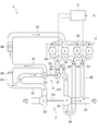
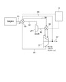
- FIG. 2 It is a mimetic diagram showing the 2 stage turbo system applied to the engine concerning one embodiment of the present invention.
- an expression indicating that things such as “identical”, “equal”, and “homogeneous” are in an equal state not only represents an exactly equal state, but also has a tolerance or a difference that can provide the same function. It also represents the existing state.
- expressions representing shapes such as quadrangular shapes and cylindrical shapes represent not only geometrically strict shapes such as quadrangular shapes and cylindrical shapes, but also irregularities and chamfers as long as the same effects can be obtained. A shape including a part or the like is also expressed.
- the expressions “comprising”, “comprising”, “comprising”, “including”, or “having” one constituent element are not exclusive expressions for excluding the existence of the other constituent elements.
- FIG. 1 is a schematic diagram showing a two-stage turbo system 1 applied to an engine 7 according to an embodiment of the present invention.
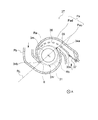
- FIG. 2 is a schematic view of the scroll part 3S of the low-pressure stage turbine 3T of the low-pressure stage turbocharger 3 according to the embodiment of the present invention.
- the scroll part 3S has a double scroll structure including two scroll passages P.
- 3 is a cross-sectional view of the scroll portion 3S of the low-pressure turbine 3T of the low-pressure turbocharger 3 according to the embodiment of the present invention cut along the circumferential direction, and a part of the scroll portion 3S of FIG. It is the figure seen from A direction.
- FIG. 1 is a schematic diagram showing a two-stage turbo system 1 applied to an engine 7 according to an embodiment of the present invention.
- FIG. 2 is a schematic view of the scroll part 3S of the low-pressure stage turbine 3T of the low-pressure stage turbocharger 3 according to the embodiment of the present invention.
- the scroll part 3S has a
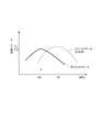
- FIG. 4 is a diagram for explaining the U / C0 characteristic of the low-pressure turbocharger having the scroll unit 3S having the double scroll structure according to the embodiment of the present invention.
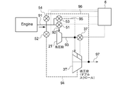
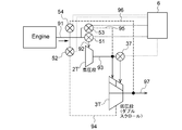
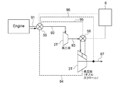
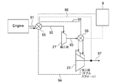
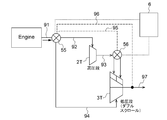
- 5A to 5B are schematic views showing the exhaust passage 9 side of the two-stage turbo system 1 according to one embodiment of the present invention in a simplified manner.
- 6B to 6E are schematic diagrams for explaining the operation mode of the two-stage turbo system 1 corresponding to FIG. 5A.
- 7B to 7E are schematic diagrams for explaining the operation mode of the two-stage turbo system 1 corresponding to FIG. 5B.
- the two-stage turbo system 1 is a supercharging system applied to the engine 7.
- the engine 7 is a diesel engine or a gasoline engine having one or more cylinders (four cylinders in FIG. 1).
- the two-stage turbo system 1 can be applied to engines 7 in various fields such as automobiles, trucks, buses, ships, and industrial engines.
- the two-stage turbo system 1 includes two superchargers (turbo), a high-pressure stage supercharger 2 and a low-pressure stage supercharger 3.
- These turbochargers are both a compressor C (2C, 3C) installed in the intake passage 8 of the engine 7 and an exhaust passage 9 of the engine 7.
- a turbine T (2T, 3T) installed in the vehicle.
- the turbine T includes a turbine housing and a turbine wheel (reference numeral 31 in FIG. 3), and the compressor C includes a compressor housing and a compressor wheel.
- the compressor wheel of the compressor C and the turbine wheel 31 of the turbine T are coupled by a shaft m (2 m, 3 m).
- the turbine wheel is driven to rotate.
- the compressor wheel coupled to the turbine wheel 31 coaxially with the shaft m is rotationally driven, and the intake air flowing through the intake passage 8 is compressed.
- the rotational drive of the turbine T is performed by blowing the exhaust gas that has passed through the scroll portion S of the supercharger from the nozzle flow path E to the turbine wheel (see FIG. 3).
- high-pressure stage supercharger 2 and low-pressure stage supercharger 3 are connected in series in the two-stage turbo system 1. Specifically, as shown in FIGS. 1 and 5A to 7E, in the exhaust passage 9, the turbine T (high pressure stage turbine 2T) of the high pressure supercharger 2 is relatively moved in the exhaust gas flow direction.
- the turbine T (low-pressure stage turbine 3T) of the low-pressure supercharger 3 that is installed on the upstream side of the exhaust passage 9 that is closer to the engine 7 is relatively engineered in the exhaust gas flow direction than the high-pressure stage turbine 2T. 7 on the downstream side of the exhaust passage 9, which is on the side far from 7.
- the compressor C (low pressure stage compressor 3C) of the low pressure supercharger 3 is installed upstream of the intake passage 8, and the compressor C (high pressure stage compressor 2C) of the high pressure supercharger 2 is These are installed in the intake passage 8 on the downstream side of the low pressure compressor 3C (see FIG. 1).
- the two superchargers are installed in series in the intake passage 8 and the exhaust passage 9.
- the low pressure supercharger 3 is larger than the high pressure supercharger 2.
- the larger the turbocharger the weight increases, and the inertial force increases as the weight increases. For this reason, as the turbocharger becomes larger, the rotational speed of the turbine T at the low speed of the engine 7 is less likely to increase, and the response performance is inferior.
- a large turbocharger is superior in turbine efficiency in a region where the flow rate of exhaust gas is larger than that of a small supercharger.
- the small turbocharger is superior in turbine efficiency in the region where the exhaust gas flow rate is small compared to the large supercharger, and the turbine T is efficiently driven to rotate with a small exhaust gas flow rate.
- the two-stage turbo system 1 covers the flow range on the small flow rate side with a relatively small high-pressure stage turbocharger 2, and a relatively large low-pressure stage turbocharger.
- the feeder 3 is configured to cover the flow rate range on the large flow rate side.
- the two-stage turbo system 1 controls the valve device 5 installed in the exhaust passage 9 by the control device 6, for example, so that the flow path of the exhaust passage 9 ( By switching exhaust gas passages I to V, which will be described later, the operation mode (supercharger to be used) is switched between one-stage supercharging and two-stage supercharging. This improves the response of the engine 7 at low speed while generating the necessary supercharging pressure over a wide operating range of the engine 7.
- the above-described one-stage supercharging means an operation mode in which supercharging to the engine 7 is performed using only the low-pressure stage supercharger 3, and the two-stage supercharging is the high-pressure stage supercharger 2 and the low-pressure stage supercharger. This means an operation mode in which supercharging is performed using both of the feeders 3.
- the scroll part 3S of the low-pressure turbine 3T of the supercharger (low-pressure supercharger 3) according to the embodiment of the present invention will be described with reference to FIGS.
- the scroll portion 3S constitutes a part of the turbine housing.
- the scroll portion 3S of the low-pressure turbine 3T of the present embodiment has at least two scroll passages P, that is, a first scroll passage Pa and a second scroll passage Pb.
- the second range Rb of E is configured not to overlap in the circumferential direction of the nozzle flow path E.
- the nozzle flow path E is located at a boundary where the wheel housing chamber 31r in which the turbine wheel 31 is housed and the scroll portion 3S are connected, and is surrounded by the inner wall of the turbine housing around the turbine wheel 31 of the low-pressure turbine 3T. (See FIG. 3).
- the gas flows from the inlet 32 (see FIG.
- the exhaust gas is blown to the turbine wheel 31 through the first range Ra of the nozzle flow path E, and the exhaust gas that has passed through the second scroll passage Pa is blown to the turbine wheel 31 through the second range Rb of the nozzle flow path E. It is configured as follows. The exhaust gas is blown from the nozzle flow path E to the turbine wheel 31 and then flows through the low pressure stage downstream passage 97 from the outlet 33 of the low pressure stage turbine 3T provided along the axial direction of the rotation axis L of the shaft m.
- the scroll portion 3S of the low-pressure turbine 3T has the first scroll passage Pa and the second scroll. It has a double scroll structure constituted by two scroll passages P of the passage Pb. More specifically, in the double scroll structure, the first scroll passage Pa and the second scroll passage Pb are arranged side by side in the circumferential direction.
- the nozzle flow path E is formed in an annular shape around the entire outer periphery of the turbine wheel 31 shown in a circular shape.
- the turbine housing has a tongue portion (first tongue portion 34a) on the side to which a radially inner road wall of the first scroll passage Pa is connected, and a radially outer side of the first scroll passage Pa.
- Two tongue portions 34 of the tongue portion (second tongue portion 34b) on the side to which the road wall is connected are formed.
- the tongue portion on the side to which the outer circumferential road wall of the second scroll passage Pa is connected is the first tongue portion 34a, and the inner road wall of the second scroll passage Pa is connected.
- the side tongue is the second tongue 34b.
- the boundary line RL Is the boundary line RL
- the first range Ra of the nozzle flow path E is formed on one side (half-circumferential portion) across the boundary line RL
- the second range Rb of the nozzle flow path E is the boundary line RL. It is formed on the other side (half-circumferential portion) sandwiching.
- the scroll portion 3S is formed so that the first range Ra and the second range Rb do not have a range (portion) overlapping each other.
- the road wall of the first scroll passage Pa and the road wall of the second scroll passage Pb are connected to different portions of the turbine housing forming the nozzle flow path E (see FIG. 2).
- the size of the nozzle flow path E when the entire flow rate of the exhaust gas is introduced is smaller than that introduced separately in both of the two scroll passages P (Pa, Pb).
- the first range Ra and the second range Rb have the same angular range (same size), and the nozzle flow path can introduce exhaust gas from one scroll path.
- the range of E is about half of the entire circumference of the nozzle flow path E.
- the low-pressure turbine 3T can be driven more quickly when the engine 7 is at a low speed.
- each of the two passages of the twin scroll is The exhaust gas is configured to be introduced uniformly over the entire circumference of the turbine wheel 31. That is, the range of the nozzle flow path E into which the exhaust gas flowing through each of the two passages of the twin scroll is introduced coincides with each other, and the range of the nozzle flow path E through which each of the two scroll passages communicates is the nozzle flow path. E have overlapping portions in the circumferential direction.
- the turbine efficiency with respect to the speed ratio (U / C0) between the peripheral speed and the theoretical speed of the turbine T is obtained.
- U / C0 characteristic the highest point of the turbine efficiency of the low-pressure turbine 3T can be shifted to the lower speed ratio side than the highest point of the turbine efficiency when the twin scroll is provided.
- the U / C0 characteristic indicates the relationship between the turbine operating speed ratio (U / C0), which is the speed ratio between the peripheral speed (U) of the turbine T and the theoretical speed (C0), and the turbine efficiency.
- (U / C0) is represented on the horizontal axis and turbine efficiency is represented on the vertical axis.
- the peripheral speed (U) of the turbine T is the rotational speed obtained from the rotational speed of the turbine T
- the theoretical speed (C0) of the turbine T is defined from the pressure ratio between the inlet and outlet of the turbine T and the inlet temperature. Is the speed to be.
- the fact that the highest point of the turbine efficiency in the U / C0 characteristic shifts to the low speed ratio side starts the rotation of the turbine T where the peripheral speed (U) of the turbine T is smaller than the theoretical speed (C0). This means that the engine is efficient at low speeds. For this reason, when the flow rate of the exhaust gas is small, such as when the engine 7 is at a low speed, the low-pressure turbine 3T can be efficiently rotated.
- the U / C0 characteristics of two superchargers differing only in the scroll part structure such as a twin scroll structure or a double scroll structure are shown.
- the turbine operating speed ratio of the highest turbine efficiency ( ⁇ t) of the turbocharger having a twin scroll is Vt
- the turbine of the highest turbine efficiency ( ⁇ d) of the turbocharger having a double scroll structure is used.
- the operating speed ratio is Vd.
- the U / C0 characteristics of both have a mountain shape with respect to the horizontal axis, with the speed ratio corresponding to the highest point ( ⁇ t, ⁇ d) as a boundary.
- the first scroll passage Pa connected to the first low pressure stage introduction passage 93 is: A partition wall 35 provided along the flow direction of the exhaust gas in a predetermined range in the first scroll passage Pa, and a flow rate control valve 37 provided upstream of the partition wall 35 are provided.
- the partition wall 35 divides the first scroll passage Pa into an outer peripheral side scroll passage Po and an inner peripheral side scroll passage Pi located on the inner peripheral side with respect to the outer peripheral side scroll passage Po, and the outer peripheral side scroll passage Po.
- a communication hole 36 that communicates with the inner scroll passage Pi.
- the flow rate control valve 37 is provided on the upstream side of the partition wall 35 and is a valve for adjusting the flow rate of exhaust gas flowing through the outer peripheral side scroll passage Po and the inner peripheral side scroll passage Pi.
- the nozzle of the first scroll passage Pa is located on the inner peripheral side scroll passage Pi from the line connecting the center of the shaft m and the tip of the first tongue portion 34a (that is, the boundary line RL in FIG. 3). It is assumed that the part on the flow path E side is the part facing the first range Ra of the nozzle flow path E (downstream part Pad) and the part upstream of the downstream part Pad (upstream part Pau). In this case, the flow control valve 37 is located in the upstream portion Pau.
- the partition wall 35 is formed so as to straddle the downstream portion Pad and the upstream portion Pau, and on the upstream side of the partition wall 35. The end 35 s is located on the downstream side of the flow control valve 37.
- a plurality of the communication holes 36 are formed in the partition wall 35 located in the upstream portion Pau.
- the flow control valve 37 when the flow control valve 37 is in a fully closed state, the flow control valve 37 is an exhaust gas flowing into the first scroll passage Pa.
- the flow rate control valve 37 When the flow rate control valve 37 is in the open state, the exhaust gas flowing into the first scroll passage Pa flows between the inner scroll passage Pi and the outer scroll passage Po. Configured to flow in both. More specifically, the flow control valve 37 has a length that reaches from the rotary shaft 37o of the flow control valve 37 provided on the outer peripheral wall surface side of the first scroll passage Pa to the upstream end portion 35s of the partition wall 35. have.
- the flow control valve 37 rotates around the rotation shaft 37o with the upstream end 35s of the partition wall 35 as a valve seat, so that the tip of the flow control valve 37 is seated on the valve seat.
- the flow control valve 37 is in the fully closed state, the entire amount of exhaust gas flowing into the first scroll passage Pa flows through the inner scroll passage Pi.
- the flow path area of the first scroll passage Pa through which the exhaust gas flows is reduced by the flow path area of the outer scroll path Po, and passes through the inner scroll path Pi.
- the flow rate of the exhaust gas can be increased, and the rotational torque of the turbine T can be increased.
- the flow control valve 37 when the flow control valve 37 is in an open state that is not in a fully closed state, the exhaust gas flowing into the first scroll passage Pa flows to both the inner scroll passage Pi and the outer scroll passage Po. It is configured. In this valve open state, the exhaust gas that has flowed through the outer peripheral side scroll passage Po flows through the upstream portion Pau of the first scroll passage Pa along the partition wall 35, and then from the communication hole 36 formed in the downstream portion Pad. It is introduced into the first range of the nozzle flow path E via the inner peripheral side scroll passage Pi. In addition, the rotational torque of the turbine T can be prevented from increasing more than necessary by lowering the gas flow rate than when the flow rate control valve 37 is in the closed state.
- the partition wall 35 and the flow rate control valve 37 are provided in the first scroll passage Pa, but may be provided in the second scroll passage Pb in the same manner.
- the scroll unit 3S including the double scroll structure and including the partition wall 35 and the flow rate control valve 37 is applied to the low-pressure stage turbine 3T, but is not limited to this embodiment.
- the scroll part 3S of the embodiment may be applied to the high-pressure turbine 2T, and the scroll part 3S of the supercharger is used regardless of whether or not the two-stage turbo system 1 is configured. May be applied.
- the scroll portion 3S of the low-pressure stage turbine 3T of the low-pressure stage supercharger 3 includes at least the first scroll path Pa and the second scroll path Pb.
- the first scroll passage Pa is divided (formed) into an outer peripheral scroll passage Po and an inner peripheral scroll passage Pi, and the flow rates of the two passages can be adjusted.
- each of the first scroll passage Pa and the second scroll passage Pb is configured to partially introduce exhaust gas from different directions with respect to the nozzle passage E formed around the turbine wheel 31. . That is, the scroll portion 3S of the low-pressure stage turbine 3T allows exhaust gas discharged from the engine 7 to flow only in a part of the plurality of scroll passages P (the first scroll passage Pa in FIGS. 1 to 4).
- the range of the nozzle flow path E for introducing the exhaust gas can be limited to a part thereof. For this reason, when exhaust gas is introduced into a partial range of the nozzle flow path E by limiting to a part of the plurality of scroll passages P, the exhaust gas is introduced into the entire range of the nozzle flow path E. As compared with the case, the flow velocity and pressure of the exhaust gas when passing through the turbine wheel 31 can be increased, and the low-pressure stage turbine 3T can be driven more quickly. Further, the low-pressure stage turbine 3T is configured to allow the exhaust gas flowing into the first scroll passage Pa to flow only to the inner peripheral scroll passage Pi, and by flowing the exhaust gas only to the inner peripheral scroll passage Pi. The low-pressure turbine 3T can be driven more rapidly by increasing the flow rate and pressure of the exhaust gas.
- each of the plurality of scroll passages P is configured so as not to overlap in the circumferential direction of the nozzle passage E, the range of the nozzle passage E corresponding to each scroll passage P such as a twin scroll is in the circumferential direction.
- the highest point of the turbine efficiency in the U / C0 characteristic can be shifted to the low speed ratio side as compared with the case where they are configured to overlap. That is, the turbine efficiency on the low speed ratio side can be increased. For this reason, when the flow rate of the exhaust gas is small (low speed ratio side) such as when the engine 7 is running at a low speed, the low-pressure turbine 3T can be driven to rotate more efficiently.
- the scroll portion 3S having such characteristics in the low-pressure turbine 3T the large-sized low-pressure turbine 3T of the two-stage turbo system 1 can be driven more quickly and efficiently, and the supercharging response Can be improved.
- the response performance of the conventional low-pressure stage turbocharger is inferior at the low engine speed as described above, the supercharging pressure required at the low speed of the engine 7 is mainly provided by the high-pressure stage turbocharger.
- the contribution by the low pressure supercharger 3 can be increased, and the response is improved.
- the entire circumference of the nozzle flow path E is bisected by the first range Ra and the second range Rb that do not overlap each other across the boundary line RL.
- the present invention is not limited to this embodiment, and the entire range including the first range Ra and the second range Rb may not be the entire circumference of the nozzle flow path E.
- the exhaust gas that has passed through the scroll passage P may not be directly introduced into a part of the annular nozzle flow path E. 1 to 7E
- the angle range of the first range Ra and the angle range of the second range Rb are the same, but in some other embodiments, the first range Ra And the angle range of the second range Rb may be different.
- the scroll portion 3S of the low-pressure stage turbine 3T has a double scroll structure as described above, but in other embodiments, the scroll portion 3S of the low-pressure stage turbine 3T. May be provided with two or more scroll passages P. In this case, the scroll portion 3S is formed so that the ranges of the nozzle flow paths E corresponding to each of the at least two scroll paths P (the first scroll path Pa and the second scroll path Pb) do not overlap.
- FIGS. 1 and 5A to 7E the overall configuration of the engine 7 to which the two-stage turbo system 1 is applied will be described with reference to FIGS. 1 and 5A to 7E.
- the intake passage 8 of the engine 7 is omitted in FIGS. 5A to 7E, it is assumed that the intake passage 8 shown in FIG.
- the intake passage 8 of the engine 7 is provided with two flow paths. Specifically, the intake passage 8 of the engine 7 flows through the main intake passage 81 for supplying intake air (air) taken from an intake duct (not shown) toward the engine 7 and the main intake passage 81.
- the intake manifold 82 for distributing the intake air to each of the plurality of cylinders of the engine 7 and a high-pressure compressor bypass passage 83 are provided.
- a compressor bypass valve 85 is installed in the high-pressure stage compressor bypass passage 83. And the flow path on the intake passage 8 through which intake air passes is determined by controlling the opening degree of the compressor bypass valve 85 by a control device 6 (described later) or the like.
- the first flow passage is a flow passage constituted by a main intake passage 81 and an intake manifold 82.
- a low-pressure compressor 3C of the low-pressure supercharger 3 in order from the upstream side, a low-pressure compressor 3C of the low-pressure supercharger 3, a high-pressure compressor 2C of the high-pressure supercharger 2, and an intercooler 84 for increasing the intake air density by cooling, Is installed.
- the intake air sequentially passes through the main intake passage 81 in this order and then passes through the intake manifold 82, so that the intake air is supplied to the engine 7 from the intake duct without passing through the high-pressure compressor bypass passage 83.
- the second flow path is composed of a main intake passage 81, a high-pressure compressor bypass passage 83, and an intake manifold 82, and is a passage through which intake air can pass only when the compressor bypass valve 85 is opened.
- Both ends of the high pressure compressor bypass passage 83 are connected to the vicinity of the outlet of the low pressure compressor 3C (downstream side) and the vicinity of the inlet of the intercooler 84 (upstream side) in the main intake passage 81, respectively.
- the intake air is supplied to the engine 7 from the intake duct by sequentially passing through the low-pressure compressor 3C, the high-pressure compressor bypass passage 83, the intercooler 84, and the intake manifold 82 of the low-pressure supercharger 3.
- the two-stage turbo system 1 is configured to perform only one-stage supercharging of the low-pressure stage supercharger 3 when the engine 7 is at a high speed. It is possible to prevent a decrease in pressure loss due to the passage of the high-pressure compressor 2C of the supercharger 3.
- the exhaust passage 9 of the engine 7 has an exhaust manifold 91 that collects exhaust gas (combustion gas) discharged from each of the plurality of cylinders of the engine 7, and each of the five flow paths described above includes This is common in that it is connected to the engine 7 via the exhaust manifold 91. Each of the above five flow paths will be described (see FIGS. 5A to 7E).
- the first flow path allows the exhaust gas discharged from the engine 7 to pass through the high-pressure turbine 2T and the inner scroll passage Pi (in the first scroll passage Pa of the low-pressure turbine 3T).
- the flow path is appropriately supplied to the inner peripheral side scroll passage Pi) of the low-pressure stage turbine 3T.
- the exhaust passage 9 includes a high-pressure stage introduction passage 92 that connects the engine 7 and the inlet (scroll portion 2S) of the high-pressure stage turbine 2T, and an outlet side of the high-pressure stage turbine 2T.
- the first low pressure stage introduction passage 93 is connected to the first scroll passage Pa of the low pressure stage turbine 3T.
- the exhaust gas discharged from the engine 7 sequentially passes through the high pressure stage introduction passage 92 and the first low pressure stage introduction passage 93, and then the inner scroll side passage of the first scroll passage Pa. It is formed to be supplied to Pi.
- the second flow path allows the exhaust gas discharged from the engine 7 to pass through the high-pressure turbine 2T and the outer peripheral scroll passage Po (hereinafter referred to as the first scroll passage Pa of the low-pressure turbine 3T).
- the flow path is appropriately supplied to the outer peripheral side scroll passage Po) of the low-pressure stage turbine 3T.
- the exhaust passage 9 includes the high-pressure stage introduction passage 92 and the first low-pressure stage introduction passage 93 as described above.
- the outer peripheral side scroll passage Po of the second scroll passage Pb is formed so that it may be supplied.
- the third flow path is a flow path for supplying the exhaust gas discharged from the engine 7 to the second scroll passage Pb of the low pressure stage turbine 3T while bypassing the high pressure stage turbine 2T.
- the exhaust passage 9 bypasses the high-pressure stage turbine 2T, and connects the engine 7 and the second scroll passage Pb of the low-pressure stage turbine 3T to the second low-pressure stage introduction passage. 94.
- the exhaust gas passage III passes through the second low-pressure stage introduction passage 94 so that the exhaust gas discharged from the engine 7 bypasses the high-pressure turbine 2T, and the second scroll passage of the low-pressure turbine 3T. It is formed so as to be directly supplied to Pb.
- the two-stage turbo system 1 introduces the exhaust gas that has passed through the high-pressure turbine 2T into the first scroll passage Pa of the low-pressure turbine 3T, and the high-pressure turbine into the second scroll passage Pb.
- the exhaust gas can be directly introduced into the low-pressure turbine 3T without passing through 2T.
- the two-stage turbo system 1 uses the high-pressure turbocharger 3 to improve the supercharging response when the rotational speed of the engine 7 is equal to or lower than the middle rotation range, as will be described later. To perform supercharging. In such a case, by introducing the exhaust gas from the first scroll passage Pa into the nozzle passage E, the flow rate of the exhaust gas after driving the high-pressure turbine 2T is increased when the nozzle passage E is introduced.
- the large-sized low-pressure turbine 3T of the two-stage turbo system 1 can be rotated more quickly and efficiently. Further, when the flow rate of the exhaust gas is small, such as when the engine 7 is on the low rotation side (extremely low rotation region) of the low rotation region, the flow control valve 37 is operated to exhaust the exhaust gas only to the inner scroll passage Pi. Can be further improved in response to supercharging.
- the fourth flow path passes the exhaust gas discharged from the engine 7 without passing through the high-pressure stage turbine 2T, and the inner and outer scroll paths Pi and Pi of the low-pressure stage turbine 3T.
- the flow path supplies at least one of Po (both in FIGS. 1 to 7E).
- the exhaust passage 9 has a high-pressure stage bypass passage 95 that bypasses the high-pressure turbine 2T and connects the engine 7 and the first scroll passage Pa of the low-pressure turbine 3T. is doing.
- the high-pressure stage bypass passage 95 connects the high-pressure stage introduction passage 92 and the first low-pressure stage introduction passage 93 described above, thereby bypassing the high-pressure stage turbine 2T and the first stage of the engine 7 and the low-pressure stage turbine 3T.
- the scroll passage Pa is connected.
- the high-pressure stage bypass passage 95 may connect the exhaust manifold 91 and the first low-pressure stage introduction passage 93.
- the exhaust gas passage IV passes through the high-pressure stage bypass passage 95 so that the exhaust gas discharged from the engine 7 bypasses the high-pressure stage turbine 2T, and enters the first scroll passage Pa of the low-pressure stage turbine 3T. It is configured to be supplied directly.
- the fifth channel allows the exhaust gas discharged from the engine 7 to enter the exhaust channel 9 downstream of the low-pressure turbine 3T without passing through both the high-pressure turbine 2T and the low-pressure turbine 3T. It is a flow path to supply.
- the exhaust passage 9 has a low-pressure stage bypass passage 96 that bypasses the low-pressure stage turbine 3T and connects the upstream side and the downstream side of the low-pressure stage turbine 3T.
- the low pressure stage bypass passage 96 connects the exhaust manifold 91 and a low pressure stage downstream passage 97 connected to the outlet of the low pressure turbine 3T.
- the flow rate of exhaust gas flowing through the first scroll passage Pa and the second scroll passage Pb of the low-pressure turbine 3T can be reduced simultaneously.
- the second low-pressure stage introduction passage 94 and the low-pressure stage downstream passage 97 may be connected.
- a valve device 5 capable of adjusting the flow rate of the exhaust gas flowing through the above-described five flow paths is installed in the exhaust passage 9 of the engine 7.
- the valve device 5 includes the high pressure stage introduction passage 92, the first low pressure stage introduction passage 93, the inner peripheral side scroll passage Pi, the outer peripheral side scroll passage Po, and the second low pressure stage.
- the flow rate of the exhaust gas flowing through each of the introduction passage 94, the high-pressure stage bypass passage 95, and the low-pressure stage bypass passage 96 is configured to be adjustable.
- the high-pressure stage turbocharger 2 and the low-pressure stage supercharger 3 can be switched, and the scroll passage P in the scroll portion 3S of the low-pressure stage turbine 3T of the low-pressure stage turbocharger 3 can be switched. It is possible to provide the two-stage turbo system 1 having excellent supercharging response while generating necessary supercharging pressure over a wide operating range.
- valve device 5 is installed in the flow rate control valve 37 and the high-pressure stage introduction passage 92.
- At least one of the above-described valves (37, 51 to 54) may be a valve whose opening degree can be adjusted between the fully open position and the fully closed position (linear control is possible). It may be possible to selectively switch between full open and full closed.
- the flow rate ratio of the exhaust gas flowing through the first scroll passage Pa and the second scroll passage Pb of the low-pressure turbine 3T is adjusted by making at least the first valve 51 or the second valve 52 a linear controllable valve. It becomes possible. Accordingly, as will be described later, the high pressure stage introduction passage 92, the first low pressure stage introduction passage 93, the inner peripheral side scroll passage Pi, the outer peripheral side scroll passage Po, the second low pressure stage introduction passage 94, the high pressure stage bypass passage 95, and The ratio of the flow rate of the exhaust gas flowing through each of the low-pressure stage bypass passages 96 can be adjusted by a plurality of valves (37, 51 to 54) provided in the respective passages.
- the pressure (boost pressure) on the outlet side of the low-pressure stage compressor 3C of the low-pressure supercharger 3 can be adjusted by the fourth valve 54, and abnormal operation of the low-pressure supercharger 3 such as surging can be prevented. be able to.
- the valve device 5 includes a flow control valve 37, a high pressure stage introduction passage 92, a second low pressure stage introduction passage 94, a high pressure stage. And a fifth valve 55 capable of adjusting the flow rate of the exhaust gas flowing through each of the bypass passage 95 and the low-pressure stage bypass passage 96.
- the ratio of exhaust gas flowing through each passage forming the exhaust passage 9 can be adjusted by two valves, and the pressure (boost pressure) on the outlet side of the low-pressure stage compressor 3C of the low-pressure supercharger 3 is adjusted.
- abnormal operation of the low pressure supercharger 3 such as surging can be prevented.
- the two-stage turbo system 1 is described above according to the rotational speed of the engine 7 (hereinafter, the engine rotational speed N as appropriate).
- a control device 6 for controlling the valve device 5 is further provided.
- the control device 6 is configured by a computer such as an ECU (electronic control device), and includes a CPU (processor) (not shown) and a memory (storage device) such as a ROM and a RAM. Then, the CPU operates (data calculation, etc.) according to the instructions of the program loaded in the main storage device, thereby realizing a functional unit necessary for controlling the valve device 5.
- the flow rate ratio can be adjusted appropriately according to the rotational speed of the engine 7, and the operation mode of the two-stage turbo system 1 as described below can be realized.
- the rotational speed of the engine 7 is in any one of the extremely low speed area, the low speed area, the middle speed area, and the high speed area that are arranged in order from the smallest engine speed N to the largest speed.
- the operation mode is switched depending on the condition.
- the region where the engine speed N is equal to or less than the first threshold is an extremely low rotation region (N ⁇ first threshold), and the region from the first threshold to the second threshold greater than the first threshold is the low rotation region.
- Second threshold value ⁇ N ⁇ third threshold value the region from the second threshold value to the third threshold value that is greater than or equal to the second threshold value is the middle rotation region (second threshold value ⁇ N ⁇ third threshold value), and the third The region above the threshold is the high rotation region (third threshold ⁇ N).
- second threshold value ⁇ N ⁇ third threshold value the region above the threshold is the high rotation region (third threshold ⁇ N).
- third threshold ⁇ N the high rotation region
- the two-stage turbo system 1 has an operation principle that performs supercharging by switching between two-stage supercharging and one-stage supercharging according to the rotational speed of the engine 7.
- an output of a rotation speed sensor capable of detecting the rotation speed of the engine 7 is configured to be input to the control device 6.
- the engine speed (hereinafter referred to as “engine speed N” as appropriate) is input.
- an output of a flow sensor (not shown) that can detect the flow rate of exhaust gas discharged from the engine 7 may be input to the control device 6.
- the rotational speed of the engine 7 (hereinafter referred to as “engine rotational speed” as appropriate) may be obtained from the correspondence between the detected value in FIG.
- the operation modes in the two-stage turbo system 1 in the embodiment shown in FIGS. 1 to 7E are as follows.
- FIGS. 6A and 7A are diagrams showing the first operation mode M1 when the engine speed N is in the extremely low rotation range.
- the control device 6 converts the exhaust gas discharged from the engine 7 via the high-pressure turbine 2T into the first scroll passage Pa of the low-pressure turbine 3T.
- the valve device 5 is controlled so that the exhaust gas flows only through the flow path (exhaust gas flow path I described above) supplied to the inner peripheral scroll passage Pi. That is, in the embodiment shown in FIGS. 1 to 7E, as shown in FIGS. 6A and 7A, the control device 6 allows the high-pressure stage introduction passage when the rotational speed of the engine 7 is in the extremely low rotation range.
- the valve device 5 is controlled so that the exhaust gas cannot pass through each of the stage bypass passages 96. Therefore, the exhaust gas is supplied only to the inner scroll passage Pi of the first scroll passage Pa, and the outer scroll passage Po and the second scroll passage of the first scroll passage Pa of the low-pressure supercharger 3. Not supplied to Pb.
- it is possible to improve the supercharging response while ensuring an appropriate capacity corresponding to the flow rate of the exhaust gas when the rotational speed of the engine 7 is in the extremely low rotational speed region.
- FIGS. 6B and 7B are diagrams showing the second operation mode M2 when the engine speed N is in the low speed range.
- the control device 6 converts the exhaust gas discharged from the engine 7 via the high-pressure stage turbine 2T into the first scroll passage Pa of the low-pressure stage turbine 3T.
- the exhaust gas discharged from the engine 7 is supplied to the outer scroll side Po of the low pressure stage turbine 3T via the flow path (exhaust gas flow path I described above) supplied to the inner peripheral side scroll path Pi and the high pressure stage turbine 2T.
- the valve device 5 is controlled so that the exhaust gas flows through the two flow paths (the exhaust gas flow path II described above). That is, in the embodiment shown in FIGS.
- the control device 6 allows the high pressure stage introduction passage 92 when the rotational speed of the engine 7 is in the low rotation range.
- the exhaust gas can pass through each of the first low pressure stage introduction passage 93, the inner peripheral side scroll passage Pi and the outer peripheral side scroll passage Po, and the second low pressure stage introduction passage 94, the high pressure stage bypass passage 95 and the low pressure stage bypass.
- the valve device 5 is controlled so that the exhaust gas cannot pass through each of the passages 96. For this reason, the exhaust gas is supplied only to the first scroll passage Pa (both the inner scroll passage Pi and the outer scroll passage Po) and is not supplied to the second scroll passage Pb of the low-pressure supercharger 3.
- the low-pressure supercharger 3 when the engine 7 is in the low speed region while ensuring an appropriate capacity according to the flow rate of the exhaust gas when the engine 7 is in the low speed region.
- the response of supercharging can be improved.
- FIGS. 6C and 7C are diagrams showing a third operation mode M3 in the case where the engine speed N is in the middle rotation range.
- the control device 6 converts the exhaust gas discharged from the engine 7 via the high-pressure stage turbine 2T into the first scroll passage Pa of the low-pressure stage turbine 3T.
- the exhaust gas discharged from the engine 7 is supplied to the outer scroll side Po of the low pressure stage turbine 3T via the flow path (exhaust gas flow path I described above) supplied to the inner peripheral side scroll path Pi and the high pressure stage turbine 2T.
- the valve device 5 is controlled so that the exhaust gas flows in the three flow paths with the flow path III). That is, in the embodiment shown in FIGS. 1 to 7E, as shown in FIGS. 6C and 7C, the control device 6 allows the high pressure stage introduction passage 92 when the rotational speed of the engine 7 is in the middle rotation range.
- the exhaust gas can pass through each of the first low pressure stage introduction passage 93, the inner peripheral side scroll passage Pi, the outer peripheral side scroll passage Po, and the second low pressure stage introduction passage 94, and the high pressure stage bypass passage 95 and the low pressure stage bypass.
- the valve device 5 is controlled so that the exhaust gas cannot pass through each of the passages 96.
- the exhaust gas is supplied to the first scroll passage Pa from the first scroll passage Pa and the second scroll passage Pb. Supplied to both. This improves the supercharging response by the high-pressure supercharger 2 and the low-pressure supercharger 3 while ensuring an appropriate capacity corresponding to the flow rate of the exhaust gas when the engine 7 is in the middle rotational speed range. can do.
- FIGS. 6D and 7D are diagrams showing a fourth operation mode M4 when the engine speed N is in the high speed region.
- the control device 6 bypasses the high-pressure turbine 2T, and exhaust gas exhausted from the engine 7 enters the second scroll passage Pb of the low-pressure turbine 3T.
- the exhaust gas discharged from the engine 7 without passing through the supply passage (exhaust gas passage III described above) and the high-pressure turbine 2T is passed through the inner peripheral scroll passage Pi and the outer peripheral scroll passage Po of the low-pressure turbine 3T.
- the valve device 5 is controlled so that the exhaust gas flows through at least one of the two flow paths (the exhaust gas flow path IV described above) supplied to at least one (both in FIGS. 1 to 7E).
- the control device 6 allows the high pressure stage bypass passage 95 when the rotational speed of the engine 7 is in the high speed region.
- the exhaust gas can pass through each of the first low pressure stage introduction passage 93, the inner peripheral side scroll passage Pi, the outer peripheral side scroll passage Po, and the second low pressure stage introduction passage 94, and the high pressure stage introduction passage 92 and the low pressure stage bypass.
- the valve device 5 is controlled so that the exhaust gas cannot pass through each of the passages 96. Therefore, the small high-pressure turbine 2T is in an idling state because no exhaust gas is supplied, and one-stage supercharging by the large low-pressure turbocharger 3 is executed. As a result, when the rotational speed of the engine 7 is in the high rotation region, it is possible to perform appropriate supercharging according to the large amount of exhaust gas by the low-pressure stage supercharger 3.
- FIGS. 6E and 7E are diagrams showing a fifth operation mode M5 when the engine speed N is on the high rotation side in the high rotation region.
- the control device 6 bypasses the high-pressure turbine 2T, and exhaust gas exhausted from the engine 7 enters the second scroll passage Pb of the low-pressure turbine 3T.
- the exhaust gas discharged from the engine 7 without passing through the supply passage (exhaust gas passage III described above) and the high-pressure turbine 2T is passed through the inner peripheral scroll passage Pi and the outer peripheral scroll passage Po of the low-pressure turbine 3T.
- the valve device 5 is controlled so that the exhaust gas flows through three flow paths, namely, the flow path (exhaust gas flow path V described above) that supplies the gas to the low-pressure stage downstream path 97. That is, in the embodiment shown in FIG. 1 to FIG. 7E, as shown in FIG. 6E and FIG. 7E, the control device 6 causes the rotation speed of the engine 7 to be higher than the predetermined rotation speed in the high rotation region.
- each of the first low pressure stage introduction passage 93, the inner peripheral side scroll passage Pi, the outer peripheral side scroll passage Po, the second low pressure stage introduction passage 94, the high pressure stage bypass passage 95, and the low pressure stage bypass passage 96 is provided.
- the valve device 5 is controlled so that the exhaust gas can pass and the exhaust gas cannot pass through the high-pressure stage introduction passage 92.
- the boost pressure pressure downstream of the low-pressure compressor 3C
- the boost pressure can be appropriately adjusted when the engine speed is on the high speed side of the high speed region.
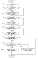
- FIG. 8 is a flowchart showing a control method of the two-stage turbo system 1 according to the embodiment of the present invention.
- the control method of the two-stage turbo system 1 includes a rotation speed acquisition step (S1) for acquiring the rotation speed of the engine 7, and an area determination step for determining a rotation speed area of the rotation speed of the engine 7. (S2, S4, S6, S8, S9) and an extremely low speed control step (S3) executed when the rotational speed of the engine 7 is in the extremely low speed range.
- the control method further includes a control step during low rotation (S5), a control step during medium rotation (S7), a control step during first high rotation (S10), and a control step during second high rotation (S11). May be.
- S5 low rotation
- S7 control step during medium rotation
- S10 control step during first high rotation
- S11 control step during second high rotation
- the control device 6 acquires the engine speed N (rotation speed acquisition step). In step S1 and subsequent steps, the control device 6 determines the rotational speed at which the rotational speed of the engine 7 is located by comparing the acquired engine rotational speed N with a threshold value of the rotational speed (the first threshold value to the third threshold value described above). The region is determined and the operation mode described above is executed based on the determination result.
- step S2 the control device 6 determines whether or not the engine speed N is in an extremely low rotation region (region determination step).
- the control device 6 executes the first operation mode M1 by controlling the valve device 5 in step S3 (control step during extremely low rotation). ). That is, the exhaust passage 9 has a single flow that can supply the exhaust gas discharged from the engine 7 to the inner peripheral scroll passage Pi of the first scroll passage Pa of the low-pressure turbine 3T via the high-pressure turbine 2T.
- a passage exhaust gas passage I described above
- step S4 the process proceeds to step S4 also when the engine speed N is not in the extremely low rotation range.
- step S4 the control device 6 determines whether or not the engine speed N is in the low rotation region (region determination step). When the engine speed N is in the low speed range, in step S5, the control device 6 controls the valve device 5 to execute the second operation mode M2 (low speed control step).
- step S6 the process proceeds to step S6 also when the engine speed N is not in the low speed range.
- step S6 the control device 6 determines whether or not the engine speed N is in the middle rotation region (region determination step).
- the control device 6 executes the third operation mode M3 by controlling the valve device 5 in step S7 (control step during middle rotation). That is, in the exhaust passage 9, the exhaust gas discharged from the engine 7 is diverted to the second scroll of the low-pressure turbine 3T while bypassing the above-described exhaust gas flow channel I, the above-described exhaust gas flow channel II, and the high-pressure turbine 2T. Three flow paths are formed together with the flow path (exhaust gas flow path III described above) to be supplied to the passage Pb (see FIGS. 6C and 7C). Thereafter, the process proceeds to the next step S8. In step S6, the process proceeds to step S8 also when the engine speed N is not in the middle rotation range.
- step S8 the control device 6 determines whether or not the engine speed N is in the high rotation region (region determination step). If the engine speed N is in the high engine speed range, in step S9, the control device 6 determines whether or not the engine speed N is equal to or greater than a predetermined engine speed (region determination step). In step S9, when the engine speed N is smaller than the predetermined speed, in step S10, the control device 6 controls the valve device 5 to execute the fourth operation mode M4 (first high speed). Control step during rotation). That is, in the exhaust passage 9, the exhaust gas discharged from the engine 7 without passing through the exhaust gas passage III and the high-pressure turbine 2T described above is sent to the inner peripheral scroll passage Pi and the outer peripheral scroll passage of the low-pressure turbine 3T. Two flow paths are formed, including the flow path (exhaust gas flow path IV described above) supplied to both Pos (see FIGS. 6D and 7D). Thereafter, the flow of FIG. 8 ends.
- step S9 the control device 6 controls the valve device 5 in step S11 to execute the fifth operation mode M5.
- step S11 the fifth operation mode M5.
- the exhaust passage 9 passes through both the high-pressure stage turbine 2T and the low-pressure stage turbine 3T to the passages (exhaust gas passage III and exhaust gas passage IV) that are formed when it is determined as the high rotation region.
- a flow path exhaust gas flow path V described above
- FIGS. 6E and 7E a total of four flow paths are formed.
- step S3 it is described that the subsequent steps are executed even after execution of step S3, step S5, and step S7.
- the present invention is not limited to this. You may complete
- the present invention is not limited to the above-described embodiments, and includes forms obtained by modifying the above-described embodiments and forms obtained by appropriately combining these forms.
Landscapes
- Engineering & Computer Science (AREA)
- Chemical & Material Sciences (AREA)
- Combustion & Propulsion (AREA)
- Mechanical Engineering (AREA)
- General Engineering & Computer Science (AREA)
- Supercharger (AREA)
Abstract
過給機は、少なくとも2つスクロール通路を有し、第1のスクロール通路を流れる排ガスが導入されるノズル流路の第1範囲と、第2のスクロール通路を流れる排ガスが導入されるノズル流路の第2範囲とが、ノズル流路の周方向において重複しないように構成されており、第1のスクロール通路は、第1のスクロール通路を、外周側スクロール通路と、外周側スクロール通路よりも内周側に位置する内周側スクロール通路とに区画するとともに、外周側スクロール通路と内周側スクロール通路とを連通する連通孔を有する区画壁と、区画壁よりも上流側に設けられ、外周側スクロール通路および内周側スクロール通路を流れる排ガスの流量を調整するための流量制御バルブと、を備える。
Description
本開示は、過給機、2ステージターボシステム、および2ステージターボシステムの制御方法に関する。
ディーゼルエンジンなどのエンジンに適用可能な過給システムとして、2ステージターボシステムが知られている。2ステージターボシステムは、既存のディーゼルエンジンに対して大幅な改良を加えることなく適用可能であり、低速でのトルクアップと高出力を両立させ、レスポンス(過渡応答性)にも優れる過給システムとして有望視される。より詳細には、2ステージターボシステムは、高圧段過給機と低圧段過給機の2つの過給機(ターボ)を直列に配置することで、排気通路に設置された各種バルブの開度制御による排気通路の流路の切り替えを通して、過給のステージの切り替えが可能な過給システムである。そして、エンジンの作動条件に応じて1ステージ過給と2ステージ過給とを切り替えることによって、エンジンの広範な作動範囲にわたって必要な過給圧を発生させつつ、低速でのレスポンスを向上させることを可能とする。一般的には、エンジンの低速時では排ガスは小流量であり、高圧段過給機、低圧段過給機の順に排ガスを流すことで2ステージ過給が行われるように排気通路の流路が切り替えられる。また、エンジンの中速時でも上記の2ステージ過給が行われるが、排ガスの一部は、高圧段過給機を通過することなく、低圧段過給機に直接流すように排気通路の切り替えが行われる。そして、エンジンの高速時には、大流量となる排ガスの全てを低圧段過給機に直接流すことで1ステージ過給が行われるように排気通路の流路が切り替えられる。
また、2ステージターボシステムの高圧段側には小型の過給機が取り付けられ、低圧段側には大型の過給機が取り付けられており、これによって、高圧段過給機の小流量側のレンジと低圧段過給機の大流量側のレンジとを活用することで、コンプレッサの作動範囲を拡大する。しかし、大型となる低圧段過給機のタービンは小型の物に比べて重さがあり、エンジンの低速時においてタービンの回転数は上昇しにくい。つまり、低圧段過給機のタービンのレスポンス性能はエンジンの低速時に劣ることから、エンジンの低速時において要求される過給圧は主に高圧段過給機によってまかなわれることになる。そこで、低圧段過給機の流量レンジを維持した上で、エンジンの低速時での低圧段過給機のレスポンスを改善する方法が提案されている(特許文献1~2)。
例えば、特許文献1には、低圧段過給機をVGターボチャージャとすることが提案されている。VGターボチャージャは、タービン側に可変ノズルベーン機構(流量可変機構)を有しており、エンジンの低速時に可変ノズルのノズル開度を絞ることで、レスポンスの向上が可能となる。また、特許文献2には、低圧段過給機のスクロール部にツインスクロールを適用することが提案されている。ツインスクロールでは、タービンの回転軸の周方向に沿って形成されたスクロール部において、回転軸の軸方向に2つの通路が並ぶような構造を有するが、排ガスの流量を2つの通路に分けてタービンに導くことで、排ガスの圧力がなまされることなくタービンを駆動することが可能となる。
また、簡易な構造で流量可変機構をもつタービンとして、VFTタービンがある(特許文献3)。このタービンは、区画壁によってスクロール部を径方向に、内周側スクロール通路と外周側スクロール通路とに分割すると共に、これらスクロール通路間を連通する連通孔(スロート)と、内周側スクロール通路あるいは両方のスクロール通路に排ガスを流入させるかを切り替える切替弁とを備え、排ガスの流量に応じて切替弁により通路を切り替えるものである。上記技術によれば、排ガスの流量が少ない時には、切替弁を作動させて内周側スクロール通路のみに排ガスを流入させることで、タービンロータに回転トルクを与えて、タービンロータを効率的に回転させることができる。また、排ガスの流量が多い時には、切替弁を作動させて外周側スクロール通路にも排ガスを流入させ、排ガスの流速を下げてタービンロータに与える回転トルクを小さくし、必要以上にタービンロータが回転することを防止することもできる。
しかしながら、特許文献1のVGターボでは、ノズルベーンを開閉するための複雑なリンク機構が必要であり、構造が複雑となる課題がある。また、特許文献2のツインスクロールを採用した過給機のU/C0特性(後述の図4参照)はシングルスクロールを採用した過給機の特性と同様であり、エンジンの低速時におけるレスポンスの大幅な改善は見込みにくい。U/C0特性とは、タービン作動速度比(U/C0)とタービン効率との関係を表す特性であり、UはタービンTの周速度、C0は、タービンの入口、出口の圧力比と、入口温度から定義される理論速度となる。また、特許文献3のVFTタービンを2ステージターボシステムへ適用することを検討しても、VFTタービンのU/C0特性はタービン作動速度比(U/C0)の小さい領域(低速度比側)でのタービン効率が高くないため、ツインスクロールと同様にレスポンスの大幅な改善は見込めない。
上述の事情に鑑みて、本発明の少なくとも一実施形態は、エンジンの広範な作動範囲にわたって必要な過給圧を発生させつつ、過給のレスポンスが向上された過給機、該過給機を備えた2ステージターボシステムを提供することを目的とする。
(1)本発明の少なくとも一実施形態に係る過給機は、
エンジンの排気通路に設置されるタービンのノズル流路に排ガスを導入するためのスクロール部を備えた過給機であって、
前記スクロール部は、第1のスクロール通路および第2のスクロール通路の少なくとも2つスクロール通路を有し、前記第1のスクロール通路を流れる前記排ガスが導入される前記ノズル流路の第1範囲と、前記第2のスクロール通路を流れる前記排ガスが導入される前記ノズル流路の第2範囲とが、前記ノズル流路の周方向において重複しないように構成されており、
前記第1のスクロール通路は、
前記第1のスクロール通路における所定範囲において前記排ガスの流れ方向に沿って設けられる区画壁であって、前記第1のスクロール通路を、外周側スクロール通路と、前記外周側スクロール通路よりも内周側に位置する内周側スクロール通路とに区画するとともに、前記外周側スクロール通路と前記内周側スクロール通路とを連通する連通孔を有する区画壁と、
前記区画壁よりも上流側に設けられ、前記外周側スクロール通路および前記内周側スクロール通路を流れる前記排ガスの流量を調整するための流量制御バルブと、を備える。
エンジンの排気通路に設置されるタービンのノズル流路に排ガスを導入するためのスクロール部を備えた過給機であって、
前記スクロール部は、第1のスクロール通路および第2のスクロール通路の少なくとも2つスクロール通路を有し、前記第1のスクロール通路を流れる前記排ガスが導入される前記ノズル流路の第1範囲と、前記第2のスクロール通路を流れる前記排ガスが導入される前記ノズル流路の第2範囲とが、前記ノズル流路の周方向において重複しないように構成されており、
前記第1のスクロール通路は、
前記第1のスクロール通路における所定範囲において前記排ガスの流れ方向に沿って設けられる区画壁であって、前記第1のスクロール通路を、外周側スクロール通路と、前記外周側スクロール通路よりも内周側に位置する内周側スクロール通路とに区画するとともに、前記外周側スクロール通路と前記内周側スクロール通路とを連通する連通孔を有する区画壁と、
前記区画壁よりも上流側に設けられ、前記外周側スクロール通路および前記内周側スクロール通路を流れる前記排ガスの流量を調整するための流量制御バルブと、を備える。
上記(1)の構成によれば、過給機のタービンのスクロール部は、少なくとも第1のスクロール通路および第2のスクロール通路を備える。また、第1のスクロール通路には外周側スクロール通路および内周側スクロール通路が区画(形成)されると共に、この2つの通路の流量が調整可能に構成される。ここで、第1のスクロール通路および第2のスクロール通路の各々は、タービンホイールの周囲に形成されるノズル流路に対して異なる方向から部分的に排ガスを導入するよう構成される。つまり、過給機のタービンのスクロール部は、複数のスクロール通路のうちの一部(例えば第1のスクロール通路)に限定してエンジンから排出された排ガスを流すことで、排ガスを導入するノズル流路の範囲をその一部に限定することが可能に構成される。このため、複数のスクロール通路のうちの一部に限定することによりノズル流路の一部の範囲に排ガスを導入する場合には、ノズル流路の全範囲に対して排ガスを導入する場合よりも、タービンホイールを通過する際の排ガスの流速や圧力を高めることができ、タービンをより迅速に駆動することができる。さらに、第1のスクロール通路の内周側スクロール通路にのみ排ガスを流すことにより、排ガスの流速や圧力を高め、タービンをより迅速に駆動することができる。
また、複数のスクロール通路の各々がノズル流路の周方向において重複しないように構成されることで、ツインスクロールやVFTタービンよりも、U/C0特性におけるタービン効率の最高点を低速度比側にシフトすることができる。つまり、低速度比側でのタービン効率を高めることができる。このため、エンジンの低速時などの排ガスの流量が少ない場合(低速度比側)において、より効率よく過給機を回転駆動させることができる。したがって、このような特徴を備えるスクロール部をタービンに採用することで、タービンをより迅速に効率良く駆動することができ、過給(過給効果)のレスポンスを向上することができる。
(2)幾つかの実施形態では、上記(1)の構成において、
前記流量制御バルブは、前記流量制御バルブが全閉状態にあるときには、前記第1のスクロール通路に流入する前記排ガスの全量が前記内周側スクロール通路を流れ、且つ、前記流量制御バルブが開弁状態にあるときには、前記第1のスクロール通路に流入する前記排ガスが前記内周側スクロール通路と前記外周側スクロール通路の両方に流れるように構成される。
前記流量制御バルブは、前記流量制御バルブが全閉状態にあるときには、前記第1のスクロール通路に流入する前記排ガスの全量が前記内周側スクロール通路を流れ、且つ、前記流量制御バルブが開弁状態にあるときには、前記第1のスクロール通路に流入する前記排ガスが前記内周側スクロール通路と前記外周側スクロール通路の両方に流れるように構成される。
上記(2)の構成によれば、流量制御バルブの状態によって排ガスの流路を、内周側スクロール通路のみか、あるいは、両方のスクロール通路かに切り替えることができる。これによって、タービンの回転トルクを調整することができる。
(3)本発明の少なくとも一実施形態に係る2ステージターボシステムは、
エンジンの排気通路に設置される高圧段タービンを有する高圧段過給機と、
上記(1)または(2)に記載の過給機であって、前記排気通路において前記高圧段タービンの下流側に設置される低圧段タービンを有する、前記高圧段過給機より大型の低圧段過給機と、を備える。
エンジンの排気通路に設置される高圧段タービンを有する高圧段過給機と、
上記(1)または(2)に記載の過給機であって、前記排気通路において前記高圧段タービンの下流側に設置される低圧段タービンを有する、前記高圧段過給機より大型の低圧段過給機と、を備える。
上記(3)の構成によれば、上記(1)または(2)の過給機は、2ステージターボシステムの低圧段過給機に用いられる。これによって、2ステージターボシステムの大型の低圧段タービンをより迅速に効率良く駆動することができ、過給のレスポンスを向上することができる。
(4)幾つかの実施形態では、上記(3)の構成において、
前記排気通路は、
前記エンジンと前記高圧段タービンの入口とを接続する高圧段導入通路と、
前記高圧段タービンの出口側と前記低圧段タービンの前記第1のスクロール通路とを接続する第1低圧段導入通路と、
前記高圧段タービンを迂回して、前記エンジンと前記低圧段タービンの前記第2のスクロール通路とを接続する第2低圧段導入通路と、を含む。
前記排気通路は、
前記エンジンと前記高圧段タービンの入口とを接続する高圧段導入通路と、
前記高圧段タービンの出口側と前記低圧段タービンの前記第1のスクロール通路とを接続する第1低圧段導入通路と、
前記高圧段タービンを迂回して、前記エンジンと前記低圧段タービンの前記第2のスクロール通路とを接続する第2低圧段導入通路と、を含む。
上記(4)の構成によれば、2ステージターボシステムは、低圧段タービンの第1のスクロール通路には高圧段タービンを通過した排ガスを導入し、第2のスクロール通路には高圧段タービンを通過することなく、低圧段タービンに排ガスを直接導入することが可能に構成される。通常、2ステージターボシステムは、エンジンの回転数が中回転領域以下にある場合には過給のレスポンスの向上のために高圧段過給機を使用して過給を実行する。このような場合など、第1のスクロール通路からノズル流路に排ガスを導入することによって、高圧段タービンを駆動した後の排ガスの流速等をノズル流路に導入する際に高めることができ、2ステージターボシステムの大型の低圧段タービンをより迅速に効率良く回転させることができる。また、エンジンの回転数が低回転領域の低回転側(極低回転領域)にある場合など排ガスの流量が少ない時には、流量制御バルブにより内周側スクロール通路のみに排ガスを流入させることによって、過給のレスポンスをさらに向上させることができる。
(5)幾つかの実施形態では、上記(4)の構成において、
前記排気通路は、
前記高圧段タービンを迂回して、前記エンジンと前記低圧段タービンの前記第1のスクロール通路とを接続する高圧段バイパス通路と、
前記低圧段タービンを迂回して前記低圧段タービンの上流側と下流側とを接続する低圧段バイパス通路と、をさらに含み、
前記高圧段導入通路、前記第1低圧段導入通路、前記内周側スクロール通路、前記外周側スクロール通路、前記第2低圧段導入通路、前記高圧段バイパス通路、および、前記低圧段バイパス通路の各々を流れる前記排ガスの流量の割合を調整可能なバルブ装置と、をさらに含む。
上記(5)の構成によれば、排気通路を形成する各通路(高圧段導入通路、第1低圧段導入通路、内周側スクロール通路、外周側スクロール通路、第2低圧段導入通路、高圧段バイパス通路、低圧段バイパス流路)を流れる排ガスの流量の割合をバルブ装置によって調整することができる。これによって、高圧段過給機や低圧段過給機の切り替えや、低圧段過給機の低圧段タービンのスクロール部におけるスクロール通路(第1のスクロール通路、第2のスクロール通路、内周側スクロール通路、外周側スクロール通路)の切り替えを行うことができ、エンジンの広範な作動範囲にわたって必要な過給圧を発生させつつ、過給のレスポンスに優れた2ステージターボシステムを提供することができる。
前記排気通路は、
前記高圧段タービンを迂回して、前記エンジンと前記低圧段タービンの前記第1のスクロール通路とを接続する高圧段バイパス通路と、
前記低圧段タービンを迂回して前記低圧段タービンの上流側と下流側とを接続する低圧段バイパス通路と、をさらに含み、
前記高圧段導入通路、前記第1低圧段導入通路、前記内周側スクロール通路、前記外周側スクロール通路、前記第2低圧段導入通路、前記高圧段バイパス通路、および、前記低圧段バイパス通路の各々を流れる前記排ガスの流量の割合を調整可能なバルブ装置と、をさらに含む。
上記(5)の構成によれば、排気通路を形成する各通路(高圧段導入通路、第1低圧段導入通路、内周側スクロール通路、外周側スクロール通路、第2低圧段導入通路、高圧段バイパス通路、低圧段バイパス流路)を流れる排ガスの流量の割合をバルブ装置によって調整することができる。これによって、高圧段過給機や低圧段過給機の切り替えや、低圧段過給機の低圧段タービンのスクロール部におけるスクロール通路(第1のスクロール通路、第2のスクロール通路、内周側スクロール通路、外周側スクロール通路)の切り替えを行うことができ、エンジンの広範な作動範囲にわたって必要な過給圧を発生させつつ、過給のレスポンスに優れた2ステージターボシステムを提供することができる。
(6)幾つかの実施形態では、上記(5)の構成において、
前記バルブ装置は、
前記流量制御バルブと、
前記高圧段導入通路に設置される第1バルブと、
前記第2低圧段導入通路に設置される第2バルブと、
前記高圧段バイパス通路に設置される第3バルブと、
前記低圧段バイパス通路に設置される第4バルブと、を有する。
上記(6)の構成によれば、排気通路を形成する各通路の各々を流れる排ガスの流量の割合を、各通路に設けられる複数のバルブによって調整することができる。また、第4バルブによって、低圧段過給機の低圧段コンプレッサの出口側の圧力(ブースト圧)を調整することができ、サージングなどの低圧段過給機の異常運転を防止することができる。
前記バルブ装置は、
前記流量制御バルブと、
前記高圧段導入通路に設置される第1バルブと、
前記第2低圧段導入通路に設置される第2バルブと、
前記高圧段バイパス通路に設置される第3バルブと、
前記低圧段バイパス通路に設置される第4バルブと、を有する。
上記(6)の構成によれば、排気通路を形成する各通路の各々を流れる排ガスの流量の割合を、各通路に設けられる複数のバルブによって調整することができる。また、第4バルブによって、低圧段過給機の低圧段コンプレッサの出口側の圧力(ブースト圧)を調整することができ、サージングなどの低圧段過給機の異常運転を防止することができる。
(7)幾つかの実施形態では、上記(5)の構成において、
前記バルブ装置は、
前記流量制御バルブと、
前記高圧段導入通路、前記第2低圧段導入通路、前記高圧段バイパス通路および前記低圧段バイパス通路の各々を流れる排ガスの流量を調整可能な第5バルブと、を有する。
上記(7)の構成によれば、排気通路を形成する各通路を流れる排ガスの割合を2つのバルブによって調整することができると共に、低圧段過給機の低圧段コンプレッサの出口側の圧力(ブースト圧)を調整することができ、サージングなどの低圧段過給機の異常運転を防止することができる。
前記バルブ装置は、
前記流量制御バルブと、
前記高圧段導入通路、前記第2低圧段導入通路、前記高圧段バイパス通路および前記低圧段バイパス通路の各々を流れる排ガスの流量を調整可能な第5バルブと、を有する。
上記(7)の構成によれば、排気通路を形成する各通路を流れる排ガスの割合を2つのバルブによって調整することができると共に、低圧段過給機の低圧段コンプレッサの出口側の圧力(ブースト圧)を調整することができ、サージングなどの低圧段過給機の異常運転を防止することができる。
(8)幾つかの実施形態では、上記(5)~(7)の構成において、
前記エンジンの回転数に応じて前記バルブ装置を制御する制御装置をさらに備える。
上記(8)の構成によれば、制御装置がバルブ装置を制御することにより、排気通路を形成する各通路の各々を流れる排ガスの流量の割合を、エンジンの回転数に応じて適切に調整することができ、2ステージターボシステムの作動モードを実現することができる。
前記エンジンの回転数に応じて前記バルブ装置を制御する制御装置をさらに備える。
上記(8)の構成によれば、制御装置がバルブ装置を制御することにより、排気通路を形成する各通路の各々を流れる排ガスの流量の割合を、エンジンの回転数に応じて適切に調整することができ、2ステージターボシステムの作動モードを実現することができる。
(9)幾つかの実施形態では、上記(8)の構成において、
前記制御装置は、前記エンジンの回転数が極低回転領域にある場合においては、前記高圧段導入通路、前記第1低圧段導入通路および内周側スクロール通路の各々を前記排ガスが通過するのを可能とし、前記外周側スクロール通路、前記第2低圧段導入通路、前記高圧段バイパス通路および前記低圧段バイパス通路の各々を前記排ガスが通過するのを不可とするように、前記バルブ装置を制御する。
上記(9)の構成によれば、エンジンの回転数が極低回転数領域にある場合には、第1のスクロール通路の内周側スクロール通路のみに高圧段タービンを経由した排ガスを流し、低圧段タービンの第1のスクロール通路の外周側スクロール通路および第2のスクロール通路には排ガスを流さないように構成することで、低圧段過給機のレスポンスを向上することができる。
前記制御装置は、前記エンジンの回転数が極低回転領域にある場合においては、前記高圧段導入通路、前記第1低圧段導入通路および内周側スクロール通路の各々を前記排ガスが通過するのを可能とし、前記外周側スクロール通路、前記第2低圧段導入通路、前記高圧段バイパス通路および前記低圧段バイパス通路の各々を前記排ガスが通過するのを不可とするように、前記バルブ装置を制御する。
上記(9)の構成によれば、エンジンの回転数が極低回転数領域にある場合には、第1のスクロール通路の内周側スクロール通路のみに高圧段タービンを経由した排ガスを流し、低圧段タービンの第1のスクロール通路の外周側スクロール通路および第2のスクロール通路には排ガスを流さないように構成することで、低圧段過給機のレスポンスを向上することができる。
(10)幾つかの実施形態では、上記(8)~(9)の構成において、
前記制御装置は、前記エンジンの回転数が低回転領域にある場合においては、前記高圧段導入通路、前記第1低圧段導入通路、前記内周側スクロール通路および前記外周側スクロール通路の各々を前記排ガスが通過するのを可能とし、前記第2低圧段導入通路、前記高圧段バイパス通路および前記低圧段バイパス通路の各々を前記排ガスが通過するのを不可とするように、前記バルブ装置を制御する。
上記(10)の構成によれば、エンジンの回転数が低回転数領域にある場合には、低圧段タービンの第2のスクロール通路には排ガスを流さず、内周側スクロール通路および外周側スクロール通路を備える第1のスクロール通路の全体に高圧段タービンを経由した排ガスを流すよう構成される。これによって、低圧段過給機において、低回転領域における排ガスの流量に応じた適切な容量を確保しつつ、過給のレスポンスを向上することができる。
前記制御装置は、前記エンジンの回転数が低回転領域にある場合においては、前記高圧段導入通路、前記第1低圧段導入通路、前記内周側スクロール通路および前記外周側スクロール通路の各々を前記排ガスが通過するのを可能とし、前記第2低圧段導入通路、前記高圧段バイパス通路および前記低圧段バイパス通路の各々を前記排ガスが通過するのを不可とするように、前記バルブ装置を制御する。
上記(10)の構成によれば、エンジンの回転数が低回転数領域にある場合には、低圧段タービンの第2のスクロール通路には排ガスを流さず、内周側スクロール通路および外周側スクロール通路を備える第1のスクロール通路の全体に高圧段タービンを経由した排ガスを流すよう構成される。これによって、低圧段過給機において、低回転領域における排ガスの流量に応じた適切な容量を確保しつつ、過給のレスポンスを向上することができる。
(11)幾つかの実施形態では、上記(8)~(10)の構成において、
前記制御装置は、前記エンジンの回転数が中回転領域にある場合においては、前記高圧段導入通路、前記第1低圧段導入通路、前記内周側スクロール通路、前記外周側スクロール通路および第2低圧段導入通路の各々を前記排ガスが通過するのを可能とし、前記高圧段バイパス通路および前記低圧段バイパス通路の各々を前記排ガスが通過するのを不可とするように、前記バルブ装置を制御する。
上記(11)の構成によれば、エンジンの回転数が中回転数領域にある場合には、低圧段タービンの内周側スクロール通路および外周側スクロール通路を備える第1のスクロール通路の全体に高圧段タービンを経由した排ガスを流すと共に、第1のスクロール通路および第2のスクロール通路の両方に排ガスを流すよう構成される。これによって、中回転領域における排ガスの流量に応じた適切な容量を確保しつつ、高圧段過給機および低圧段過給機による過給のレスポンスを向上することができる。
前記制御装置は、前記エンジンの回転数が中回転領域にある場合においては、前記高圧段導入通路、前記第1低圧段導入通路、前記内周側スクロール通路、前記外周側スクロール通路および第2低圧段導入通路の各々を前記排ガスが通過するのを可能とし、前記高圧段バイパス通路および前記低圧段バイパス通路の各々を前記排ガスが通過するのを不可とするように、前記バルブ装置を制御する。
上記(11)の構成によれば、エンジンの回転数が中回転数領域にある場合には、低圧段タービンの内周側スクロール通路および外周側スクロール通路を備える第1のスクロール通路の全体に高圧段タービンを経由した排ガスを流すと共に、第1のスクロール通路および第2のスクロール通路の両方に排ガスを流すよう構成される。これによって、中回転領域における排ガスの流量に応じた適切な容量を確保しつつ、高圧段過給機および低圧段過給機による過給のレスポンスを向上することができる。
(12)幾つかの実施形態では、上記(8)~(11)の構成において、
前記制御装置は、前記エンジンの回転数が高回転領域にある場合においては、前記高圧段バイパス通路、前記第1低圧段導入通路、前記内周側スクロール通路、前記外周側スクロール通路および第2低圧段導入通路の各々を前記排ガスが通過するのを可能とし、前記高圧段導入通路および前記低圧段バイパス通路の各々を前記排ガスが通過するのを不可とするように、前記バルブ装置を制御する。
上記(12)の構成によれば、エンジンの回転数が高回転数領域にある場合には、高圧段タービンに排ガスを流すことなく、低圧段タービンの内周側スクロール通路および外周側スクロール通路を備える第1のスクロール通路の全体および第2のスクロール通路の両方に排ガスを流すよう構成される。つまり、高回転領域における排ガスの流量に対して効率の優れた低圧段過給機のみを利用して過給を行う。これによって、低圧段過給機によって大流量の排ガスに応じた適切な過給を行うことができる。
前記制御装置は、前記エンジンの回転数が高回転領域にある場合においては、前記高圧段バイパス通路、前記第1低圧段導入通路、前記内周側スクロール通路、前記外周側スクロール通路および第2低圧段導入通路の各々を前記排ガスが通過するのを可能とし、前記高圧段導入通路および前記低圧段バイパス通路の各々を前記排ガスが通過するのを不可とするように、前記バルブ装置を制御する。
上記(12)の構成によれば、エンジンの回転数が高回転数領域にある場合には、高圧段タービンに排ガスを流すことなく、低圧段タービンの内周側スクロール通路および外周側スクロール通路を備える第1のスクロール通路の全体および第2のスクロール通路の両方に排ガスを流すよう構成される。つまり、高回転領域における排ガスの流量に対して効率の優れた低圧段過給機のみを利用して過給を行う。これによって、低圧段過給機によって大流量の排ガスに応じた適切な過給を行うことができる。
(13)幾つかの実施形態では、上記(12)の構成において、
前記制御装置は、前記エンジンの回転数が前記高回転領域における所定の回転数以上にある場合には、前記高圧段バイパス通路、前記第1低圧段導入通路、前記内周側スクロール通路、前記外周側スクロール通路、前記第2低圧段導入通路、および、前記低圧段バイパス通路の各々を前記排ガスが通過するのを可能とし、前記高圧段導入通路を前記排ガスが通過するのを不可とするように、前記バルブ装置を制御する。
上記(13)の構成によれば、高回転数領域の高回転側にエンジンの回転数がある場合においてブースト圧を適切に調整することができる。
前記制御装置は、前記エンジンの回転数が前記高回転領域における所定の回転数以上にある場合には、前記高圧段バイパス通路、前記第1低圧段導入通路、前記内周側スクロール通路、前記外周側スクロール通路、前記第2低圧段導入通路、および、前記低圧段バイパス通路の各々を前記排ガスが通過するのを可能とし、前記高圧段導入通路を前記排ガスが通過するのを不可とするように、前記バルブ装置を制御する。
上記(13)の構成によれば、高回転数領域の高回転側にエンジンの回転数がある場合においてブースト圧を適切に調整することができる。
(14)本発明の少なくとも一実施形態に係る2ステージターボシステムの制御方法は、
エンジンの排気通路に設置される高圧段タービンを有する高圧段過給機と、前記排気通路において前記高圧段タービンの下流側に設置される低圧段タービンを有する、前記高圧段過給機より大型の低圧段過給機と、を備える上記(8)に記載の2ステージターボシステムの制御方法であって、
前記エンジンの回転数を取得する回転数取得ステップと、
前記エンジンの回転数の回転数領域を判定する領域判定ステップと、
前記エンジンの回転数が極低回転領域あるいは低回転領域にある場合においては、前記低圧段過給機の第1のスクロール通路を前記高圧段タービンを経由した排ガスが通過するのを可能とし、前記低圧段過給機の第2のスクロール通路を前記排ガスが通過するのを不可とするように、前記バルブ装置を制御する低回転域制御ステップと、を備える。
エンジンの排気通路に設置される高圧段タービンを有する高圧段過給機と、前記排気通路において前記高圧段タービンの下流側に設置される低圧段タービンを有する、前記高圧段過給機より大型の低圧段過給機と、を備える上記(8)に記載の2ステージターボシステムの制御方法であって、
前記エンジンの回転数を取得する回転数取得ステップと、
前記エンジンの回転数の回転数領域を判定する領域判定ステップと、
前記エンジンの回転数が極低回転領域あるいは低回転領域にある場合においては、前記低圧段過給機の第1のスクロール通路を前記高圧段タービンを経由した排ガスが通過するのを可能とし、前記低圧段過給機の第2のスクロール通路を前記排ガスが通過するのを不可とするように、前記バルブ装置を制御する低回転域制御ステップと、を備える。
上記(14)の構成によれば、上記(8)と同様に、2ステージターボシステムの過給のレスポンスを向上しつつ、エンジンの回転数に適した2ステージターボシステムの作動モードを実現することができる。
(15)幾つかの実施形態では、上記(14)の構成において、
前記エンジンの回転数が前記極低回転領域にある場合においては、前記低圧段過給機の前記第1のスクロール通路の内周側スクロール通路を前記高圧段タービンを経由した排ガスが通過するのを可能とし、前記低圧段過給機の前記第1のスクロール通路の外周側スクロール通路を前記排ガスが通過するのを不可とするように、前記バルブ装置を制御する極低回転時制御ステップを、さらに備える。
上記(15)の構成によれば、上記(9)と同様に、極低回転領域における低圧段過給機のレスポンスを向上することができる。
前記エンジンの回転数が前記極低回転領域にある場合においては、前記低圧段過給機の前記第1のスクロール通路の内周側スクロール通路を前記高圧段タービンを経由した排ガスが通過するのを可能とし、前記低圧段過給機の前記第1のスクロール通路の外周側スクロール通路を前記排ガスが通過するのを不可とするように、前記バルブ装置を制御する極低回転時制御ステップを、さらに備える。
上記(15)の構成によれば、上記(9)と同様に、極低回転領域における低圧段過給機のレスポンスを向上することができる。
(16)幾つかの実施形態では、上記(14)~(15)の構成において、
前記エンジンの回転数が前記低回転領域にある場合においては、前記低圧段過給機の第1のスクロール通路の前記内周側スクロール通路および前記外周側スクロール通路の両方を前記高圧段タービンを経由した排ガスが通過するのを可能とし、前記第2のスクロール通路を前記排ガスが通過するのを不可とするように、前記バルブ装置を制御する低回転時制御ステップを、さらに備える。
上記(16)の構成によれば、上記(10)と同様に、低圧段過給機において、エンジンの回転数が低回転領域にある場合における排ガスの流量に応じた適切な容量を確保しつつ、過給のレスポンスを向上することができる。
前記エンジンの回転数が前記低回転領域にある場合においては、前記低圧段過給機の第1のスクロール通路の前記内周側スクロール通路および前記外周側スクロール通路の両方を前記高圧段タービンを経由した排ガスが通過するのを可能とし、前記第2のスクロール通路を前記排ガスが通過するのを不可とするように、前記バルブ装置を制御する低回転時制御ステップを、さらに備える。
上記(16)の構成によれば、上記(10)と同様に、低圧段過給機において、エンジンの回転数が低回転領域にある場合における排ガスの流量に応じた適切な容量を確保しつつ、過給のレスポンスを向上することができる。
(17)幾つかの実施形態では、上記(14)~(16)の構成において、
前記エンジンの回転数が前記中回転領域にある場合においては、前記低圧段過給機の前記第1のスクロール通路の内周側スクロール通路と外周側スクロール通路を前記高圧段タービンを経由した排ガスが通過するのを可能とすると共に、前記第2のスクロール通路を排ガスが通過するのを可能とするように、前記バルブ装置を制御する中回転時制御ステップを、さらに備える。
上記(17)の構成によれば、上記(11)と同様に、エンジンの回転数が中回転領域にある場合における排ガスの流量に応じた適切な容量を確保しつつ、高圧段過給機および低圧段過給機による過給のレスポンスを向上することができる。
前記エンジンの回転数が前記中回転領域にある場合においては、前記低圧段過給機の前記第1のスクロール通路の内周側スクロール通路と外周側スクロール通路を前記高圧段タービンを経由した排ガスが通過するのを可能とすると共に、前記第2のスクロール通路を排ガスが通過するのを可能とするように、前記バルブ装置を制御する中回転時制御ステップを、さらに備える。
上記(17)の構成によれば、上記(11)と同様に、エンジンの回転数が中回転領域にある場合における排ガスの流量に応じた適切な容量を確保しつつ、高圧段過給機および低圧段過給機による過給のレスポンスを向上することができる。
本発明の少なくとも一実施形態によれば、エンジンの広範な作動範囲にわたって必要な過給圧を発生させつつ、過給のレスポンスが向上された過給機、該過給機を備えた2ステージターボシステムが提供される。
以下、添付図面を参照して本発明の幾つかの実施形態について説明する。ただし、実施形態として記載されている又は図面に示されている構成部品の寸法、材質、形状、その相対的配置等は、本発明の範囲をこれに限定する趣旨ではなく、単なる説明例にすぎない。
例えば、「ある方向に」、「ある方向に沿って」、「平行」、「直交」、「中心」、「同心」或いは「同軸」等の相対的或いは絶対的な配置を表す表現は、厳密にそのような配置を表すのみならず、公差、若しくは、同じ機能が得られる程度の角度や距離をもって相対的に変位している状態も表すものとする。
例えば、「同一」、「等しい」及び「均質」等の物事が等しい状態であることを表す表現は、厳密に等しい状態を表すのみならず、公差、若しくは、同じ機能が得られる程度の差が存在している状態も表すものとする。
例えば、四角形状や円筒形状等の形状を表す表現は、幾何学的に厳密な意味での四角形状や円筒形状等の形状を表すのみならず、同じ効果が得られる範囲で、凹凸部や面取り部等を含む形状も表すものとする。
一方、一の構成要素を「備える」、「具える」、「具備する」、「含む」、又は、「有する」という表現は、他の構成要素の存在を除外する排他的な表現ではない。
例えば、「ある方向に」、「ある方向に沿って」、「平行」、「直交」、「中心」、「同心」或いは「同軸」等の相対的或いは絶対的な配置を表す表現は、厳密にそのような配置を表すのみならず、公差、若しくは、同じ機能が得られる程度の角度や距離をもって相対的に変位している状態も表すものとする。
例えば、「同一」、「等しい」及び「均質」等の物事が等しい状態であることを表す表現は、厳密に等しい状態を表すのみならず、公差、若しくは、同じ機能が得られる程度の差が存在している状態も表すものとする。
例えば、四角形状や円筒形状等の形状を表す表現は、幾何学的に厳密な意味での四角形状や円筒形状等の形状を表すのみならず、同じ効果が得られる範囲で、凹凸部や面取り部等を含む形状も表すものとする。
一方、一の構成要素を「備える」、「具える」、「具備する」、「含む」、又は、「有する」という表現は、他の構成要素の存在を除外する排他的な表現ではない。
図1は、本発明の一実施形態に係るエンジン7に適用された2ステージターボシステム1を示す模式図である。図2は、本発明の一実施形態に係る低圧段過給機3の低圧段タービン3Tのスクロール部3Sの模式図であり、スクロール部3Sは2つのスクロール通路Pを備えるダブルスクロール構造を有する。図3は、本発明の一実施形態に係る低圧段過給機3の低圧段タービン3Tのスクロール部3Sを周方向に沿って切断した断面図であり、図2のスクロール部3Sの一部をA方向から見た図である。図4は、本発明の一実施形態に係るダブルスクロール構造を有するスクロール部3Sを有する低圧段過給機のU/C0特性を説明するための図である。図5A~図5Bは、本発明の一実施形態に係る2ステージターボシステム1の排気通路9側を簡略化して示した模式図である。図6B~図6Eは、図5Aに対応した2ステージターボシステム1の作動モードを説明するための模式図である。また、図7B~図7Eは、図5Bに対応した2ステージターボシステム1の作動モードを説明するための模式図である。
図1~図7Eに示されるように、2ステージターボシステム1はエンジン7に適用される過給システムである。エンジン7は1以上の気筒(図1では4気筒)を備えたディーゼルエンジンやガソリンエンジンなどである。また、2ステージターボシステム1は、自動車、トラック、バス、船舶、産業用エンジン等の様々な分野のエンジン7に適用可能である。
以下の実施形態では、本発明の一実施形態にかかる過給機を2ステージターボシステム1における低圧段過給機3に適用した場合を例にして説明する。
図1~図7Eに示されるように、2ステージターボシステム1は、高圧段過給機2と低圧段過給機3の2つの過給機(ターボ)を備える。これらの過給機(高圧段過給機2や低圧段過給機3)は、いずれも、エンジン7の吸気通路8に設置されるコンプレッサC(2C、3C)と、エンジン7の排気通路9に設置されるタービンT(2T、3T)とを備える。タービンTはタービンハウジングとタービンホイール(図3の符号31)とで構成され、コンプレッサCはコンプレッサハウジングとコンプレッサホイールとで構成される。また、コンプレッサCのコンプレッサホイールとタービンTのタービンホイール31とがシャフトm(2m、3m)で結合される。そして、エンジン7の燃焼室(不図示)から排出される排ガスは、排気通路9を通って外部に向けて流れる際にタービンホイールを回転駆動する。これにより、タービンホイール31にシャフトmに同軸で結合されたコンプレッサホイールが回転駆動され、吸気通路8を流れる吸気が圧縮される。より詳細には、タービンTの回転駆動は、過給機のスクロール部Sを通過した排ガスがノズル流路Eからタービンホイールに吹き付けられること行われる(図3参照)。
これらの高圧段過給機2と低圧段過給機3とは、2ステージターボシステム1において直列に接続される。具体的には、図1、図5A~図7Eに示されるように、排気通路9においては、高圧段過給機2のタービンT(高圧段タービン2T)は、排ガスの流れ方向において相対的にエンジン7に近い側となる排気通路9の上流側に設置され、低圧段過給機3のタービンT(低圧段タービン3T)は、この高圧段タービン2Tよりも排ガスの流れ方向において相対的にエンジン7から遠い側となる排気通路9の下流側に設置される。他方、吸気通路8においては、低圧段過給機3のコンプレッサC(低圧段コンプレッサ3C)は吸気通路8の上流側に設置され、高圧段過給機2のコンプレッサC(高圧段コンプレッサ2C)は、この低圧段コンプレッサ3Cの下流側の吸気通路8に設置される(図1参照)。このように、上記の2つの過給機は吸気通路8および排気通路9において直列に設置される。
また、低圧段過給機3は高圧段過給機2よりも大型である。通常、過給機は大型になるほど重量が増し、重量の増加に伴って慣性力が大きくなる。このため、過給機が大型になるほど、エンジン7の低速時におけるタービンTの回転数は上昇しにくく、レスポンス性能が劣る。その一方で、大型の過給機は、小型の過給機よりも排ガスの流量が大きい領域でのタービン効率に優れる。逆に、小型の過給機は、大型の過給機に比べて、排ガスの流量が少ない領域におけるタービン効率が優れており、少ない排ガスの流量でタービンTが効率よく回転駆動される。このような過給機の特性を利用して、2ステージターボシステム1は、相対的に小型の高圧段過給機2で小流量側の流量レンジをカバーし、相対的に大型の低圧段過給機3で大流量側の流量レンジをカバーするよう構成される。
そして、2ステージターボシステム1は、後述するように、例えば制御装置6により排気通路9に設置されるバルブ装置5を制御することにより、エンジン7の作動条件に応じて排気通路9の流路(後述する排ガス流路I~V)を切り替えることで、1ステージ過給と2ステージ過給とで作動モード(使用する過給機)を切り替えるよう構成される。これによって、エンジン7の広範な作動範囲にわたって必要な過給圧を発生させつつ、エンジン7の低速時のレスポンスの向上を図っている。なお、上記の1ステージ過給は、低圧段過給機3のみを用いてエンジン7への過給を行う作動モードを意味し、2ステージ過給は、高圧段過給機2および低圧段過給機3の両方を用いて過給を行う作動モードを意味する。
ここで、本発明の一実施形態にかかる過給機(低圧段過給機3)の低圧段タービン3Tのスクロール部3Sについて、図2~図3を用いて説明する。なお、スクロール部3Sはタービンハウジングの一部を構成する。図2~図3に示されるように、本実施形態の低圧段タービン3Tのスクロール部3Sは、第1のスクロール通路Paおよび第2のスクロール通路Pbの少なくとも2つスクロール通路Pを有する。そして、図3に示されるように、第1のスクロール通路Paを流れる排ガスが導入されるノズル流路Eの第1範囲Raと、第2のスクロール通路Pbを流れる排ガスが導入されるノズル流路Eの第2範囲Rbとが、ノズル流路Eの周方向において重複しないように構成される。上記のノズル流路Eは、タービンホイール31が収容されるホイール収容室31rと、スクロール部3Sとが接続される境界に位置し、タービンハウジングの内壁によって、低圧段タービン3Tのタービンホイール31の周囲に形成された空間(流路)である(図3参照)。図1~図7Eに示される実施形態では、図3に示されるように、スクロール部S(低圧段タービン3T)の入口32(図2参照)から流入し、第1のスクロール通路Paを通過した排ガスはノズル流路Eの第1範囲Raを経てタービンホイール31に吹きつけられ、第2のスクロール通路Paを通過した排ガスはノズル流路Eの第2範囲Rbを経てタービンホイール31に吹きつけられよう構成されている。また、排ガスは、ノズル流路Eからタービンホイール31に吹きつけられ後、シャフトmの回転軸線Lの軸方向に沿って設けられた低圧段タービン3Tの出口33から低圧段下流通路97を流れる。
また、図1~図7Eに示される実施形態では、図2~図3に示されるように、低圧段タービン3Tのスクロール部3Sは、上記の第1のスクロール通路Paおよび上記の第2のスクロール通路Pbの2つスクロール通路Pから構成されたダブルスクロール構造となっている。より詳細には、ダブルスクロール構造においては、第1のスクロール通路Paおよび第2のスクロール通路Pbは周方向に並んで配置されている。
また、図1~図7Eに示される実施形態では、図3に示されるように、ノズル流路Eは、円形状で示されるタービンホイール31の外周の全周に環状に形成されている。ここで、タービンハウジングには、第1のスクロール通路Paの径方向の内側の路壁が接続される側の舌部(第1舌部34a)と、第1のスクロール通路Paの径方向の外側の路壁が接続される側の舌部(第2舌部34b)の2つの舌部34が形成されている。換言すれば、第2のスクロール通路Paの周方向の外側の路壁が接続される側の舌部が第1舌部34aであり、第2のスクロール通路Paの内側の路壁が接続される側の舌部が第2舌部34bとなる。そして、タービンホイール31の回転軸線Lの周方向に沿って切断した示される断面(図3)において、第1舌部34aと、第2舌部34bと、タービンホイール31の回転軸線Lを通る線を境界線RLとした場合、ノズル流路Eの第1範囲Raは境界線RLを挟んだ一方の側(半周部分)に形成されており、ノズル流路Eの第2範囲Rbは境界線RLを挟んだ他方の側(半周部分)に形成されている。このように、第1範囲Raと第2範囲Rbとは互いに重なる範囲(部分)を有しないようにスクロール部3Sは形成されている。換言すれば、第1のスクロール通路Paの路壁および第2のスクロール通路Pbの路壁は、ノズル流路Eを形成するタービンハウジングの異なる部分に接続される(図2参照)。
そして、後述するように、第1のスクロール通路Paおよび第2のスクロール通路Pbの2のスクロール通路Pの一方にのみエンジン7から排出された排ガスの全流量を流すように構成した場合には、この排ガスの全流量が導入される際のノズル流路Eのサイズは、2のスクロール通路P(Pa、Pb)の両方に分けて導入するよりも小さくなる。図1~図7Eに示される実施形態では、第1範囲Raと第2範囲Rbとは同じ角度範囲(同じ大きさ)を有しており、一方のスクロール通路から排ガスを導入可能なノズル流路Eの範囲はノズル流路Eの全周の半分程度になる。このため、ノズル流路Eに導入される際の排ガスの圧力がノズル流路Eの全範囲に分散されることなく(なまされることなく)、低圧段タービン3Tに排ガスを導入することが可能とり、エンジン7の低速時において低圧段タービン3Tをより迅速に駆動することができる。
これに対して、例えば、低圧段タービン3Tのスクロール部3Sにツインスクロールを採用した場合にも、ツインスクロールによる2つの通路がスクロール部3Sに形成されるが、ツインスクロールの2つの通路の各々は、タービンホイール31の全周に亘って均一に排ガスを導入するように構成される。つまり、ツインスクロールの2つの通路の各々を流れる排ガスがそれぞれ導入されるノズル流路Eの範囲は互いに一致しており、2つのスクロール通路の各々が連通するノズル流路Eの範囲はノズル流路Eの周方向において互いに重複する部分を有する。そして、2つのスクロール通路の一方にのみ排ガスの全流量を導入すると、タービンホイール31の全周にわたって排ガスは導入されることになる。このため、例えば、排ガスの流量に対してタービンTのサイズ(重量)が大きい場合には、排ガスの圧力がノズル流路Eの全範囲に対して分散される結果、特にエンジン7の低速時などの排ガスの流量が少ない作動点では十分な圧力比(各々のブレードおける圧力面と負圧面の圧力差)を得ることができず、大型の低圧段タービン3Tを迅速に回転駆動するのが困難になってしまう。
また、低圧段タービン3Tのスクロール部3Sを上述したダブルスクロール構造とすることにより、図4に示されるように、タービンTの周速度と理論速度との速度比(U/C0)に対するタービン効率であるU/C0特性において、低圧段タービン3Tのタービン効率の最高点を、ツインスクロールを備える場合のタービン効率の最高点よりも、低速度比側にシフトすることができる。U/C0特性は、タービンTの周速度(U)と理論速度(C0)との速度比となるタービン作動速度比(U/C0)とタービン効率の関係を示すものであり、タービン作動速度比(U/C0)を横軸に、タービン効率を縦軸として表される。ここで、タービンTの周速度(U)はタービンTの回転数から得られる回転速度であり、タービンTの理論速度(C0)は、タービンTの入口と出口との圧力比および入口温度から定義される速度である。そして、U/C0特性におけるタービン効率の最高点が低速度比側にシフトすることは、理論速度(C0)に対してタービンTの周速度(U)が小さい状況となるタービンTの回転し始めなどのエンジンの低速時における効率が良いことを意味する。このため、エンジン7の低速時などの排ガスの流量が少ない場合において、効率よく低圧段タービン3Tを回転させることが可能となる。
図4の例示では、ツインスクロールあるいはダブルスクロール構造といったスクロール部の構造のみが異なる2つの過給機のU/C0特性が示されている。具体的には、ツインスクロールを備える過給機のタービン効率の最高点(ηt)のタービン作動速度比はVtであり、ダブルスクロール構造を備える過給機のタービン効率の最高点(ηd)のタービン作動速度比はVdとなっている。また、両者のU/C0特性は、それぞれの最高点(ηt、ηd)に対応する速度比を境に横軸に対して山なりの形状となっている。そして、ηdはηtよりも小さく、タービン効率は小さくなるものの、VdはVtよりも小さくなっており、ツインスクロールを備える過給機の山なり形状のU/C0特性に対して、ダブルスクロール構造を備える過給機の山なり形状のU/C0特性は、全体的に、低速度比側にシフトしたようになっている。このため、両者のU/C0特性を低速度比側における同一の速度比で比べると、例えば速度比がVdでは、タービン効率はダブルスクロール構造を備える過給機の方がツインスクロールを備える過給機よりも大きく、エンジン7の低速側での効率が良いことが分かる。
また、図3に示されるように、本発明の一実施形態にかかる過給機(低圧段過給機3)において、第1低圧段導入通路93に接続される第1のスクロール通路Paは、第1のスクロール通路Paにおける所定範囲において排ガスの流れ方向に沿って設けられ区画壁35と、区画壁35よりも上流側に設けられる流量制御バルブ37とを備える。区画壁35は、第1のスクロール通路Paを、外周側スクロール通路Poと、外周側スクロール通路Poよりも内周側に位置する内周側スクロール通路Piとに区画するとともに、外周側スクロール通路Poと内周側スクロール通路Piとを連通する連通孔36を有する。流量制御バルブ37は、区画壁35よりも上流側に設けられ、外周側スクロール通路Poおよび内周側スクロール通路Piを流れる排ガスの流量を調整するためバルブである。
便宜的に、内周側スクロール通路Piを、シャフトmの中心と上述した第1舌部34aの先端とを結ぶ線(つまり、図3の境界線RL)よりも第1のスクロール通路Paのノズル流路E側となる部分であって、ノズル流路Eの第1範囲Raに面する部分(下流部分Pad)と、下流部分Padよりも上流側の部分(上流部分Pau)と呼ぶとする。この場合、流量制御バルブ37は上流部分Pauに位置する。そして、図1~図7Eに示される実施形態では、図3に示されるように、区画壁35は、下流部分Padおよび上流部分Pauに跨って形成されている共に、区画壁35の上流側の端部35sは流量制御バルブ37よりも下流側に位置している。また、上流部分Pauに位置する区画壁35の部分は、上記の連通孔36が複数形成されている。
また、図1~図7Eに示される実施形態では、図3に示されるように、流量制御バルブ37は、流量制御バルブ37が全閉状態にあるときには、第1のスクロール通路Paに流入する排ガスの全量が内周側スクロール通路Piを流れ、且つ、流量制御バルブ37が開弁状態にあるときには、第1のスクロール通路Paに流入する排ガスが内周側スクロール通路Piと外周側スクロール通路Poの両方に流れるように構成される。より詳細には、流量制御バルブ37は、第1のスクロール通路Paの外周の壁面側に設けられた流量制御バルブ37の回転軸37oから、区画壁35の上流側の端部35sまで届く長さを有している。そして、上記の区画壁35の上流側の端部35sを弁シートとして、流量制御バルブ37が回転軸37oを中心に回転することで、流量制御バルブ37の先端部分が弁シートに着座している状態となる全閉状態に流量制御バルブ37があるときには、第1のスクロール通路Paに流入する排ガスの全量が内周側スクロール通路Piを流れる。この全閉状態においては、排ガスが流れる第1のスクロール通路Paの流路面積は、外周側スクロール通路Poの流路面積の分だけ小さくなることになり、内周側スクロール通路Piを通過することにより排ガスの流速を高められ、タービンTの回転トルクを増大することができる。また、全閉状態でない状態となる開弁状態に流量制御バルブ37があるときには、第1のスクロール通路Paに流入する排ガスが内周側スクロール通路Piと外周側スクロール通路Poの両方に流れるように構成されている。この開弁状態では、外周側スクロール通路Poを流れた排ガスは、第1のスクロール通路Paの上流部分Pauを区画壁35に沿って流れた後、下流部分Padに形成された連通孔36から、内周側スクロール通路Piを経て、ノズル流路Eの第1範囲に導入される。また、流量制御バルブ37が閉弁状態にある場合よりも、ガスの流速が下げられることにより、タービンTの回転トルクを必要以上に増大するのを回避することができる。
上述した実施形態では、第1のスクロール通路Paに区画壁35と流量制御バルブ37が設けられているが、第2のスクロール通路Pbにも同様に設けられても良い。また、上述した実施形態では、ダブルスクロール構造を備えると共に、区画壁35と流量制御バルブ37とを備えるスクロール部3Sは低圧段タービン3Tに適用されているが、この実施形態には限定されず、他の幾つかの実施形態では、実施形態のスクロール部3Sは高圧段タービン2Tに適用されても良いし、2ステージターボシステム1を構成するか否かにかかわらず、過給機のスクロール部に適用されても良い。
上記の構成によれば、低圧段過給機3(過給機)の低圧段タービン3Tのスクロール部3Sは、少なくとも第1のスクロール通路Paおよび第2のスクロール通路Pbを備える。また、第1のスクロール通路Paには外周側スクロール通路Poおよび内周側スクロール通路Piが区画(形成)されると共に、この2つの通路の流量が調整可能に構成される。ここで、第1のスクロール通路Paおよび第2のスクロール通路Pbの各々は、タービンホイール31の周囲に形成されるノズル流路Eに対して異なる方向から部分的に排ガスを導入するよう構成される。つまり、低圧段タービン3Tのスクロール部3Sは、複数のスクロール通路Pのうちの一部(図1~図4では、第1のスクロール通路Pa)に限定してエンジン7から排出された排ガスを流すことで、排ガスを導入するノズル流路Eの範囲をその一部に限定することが可能に構成される。このため、複数のスクロール通路Pのうちの一部に限定することによりノズル流路Eの一部の範囲に排ガスを導入する場合には、ノズル流路Eの全範囲に対して排ガスを導入する場合よりも、タービンホイール31を通過する際の排ガスの流速や圧力を高めることができ、低圧段タービン3Tをより迅速に駆動することができる。また、低圧段タービン3Tは、第1のスクロール通路Paに流入した排ガスを内周側スクロール通路Piにのみ流すことが可能に構成されており、内周側スクロール通路Piにのみ排ガスを流すことにより、排ガスの流速や圧力を高めることで低圧段タービン3Tをより迅速に駆動することができる。
また、複数のスクロール通路Pの各々がノズル流路Eの周方向において重複しないように構成されることで、ツインスクロールといった各々のスクロール通路Pに対応するノズル流路Eの範囲がその周方向において重複するよう構成される場合よりも、U/C0特性におけるタービン効率の最高点を低速度比側にシフトすることができる。つまり、低速度比側でのタービン効率を高めることができる。このため、エンジン7の低速時などの排ガスの流量が少ない場合(低速度比側)において、より効率よく低圧段タービン3Tを回転駆動させることができる。したがって、このような特徴を備えるスクロール部3Sを低圧段タービン3Tに採用することで、2ステージターボシステム1の大型の低圧段タービン3Tをより迅速に効率良く駆動することができ、過給のレスポンスを向上することができる。この点、従来の低圧段過給機のレスポンス性能は上述したようにエンジンの低速時で劣ることから、エンジン7の低速時において要求される過給圧は主に高圧段過給機によってまかなわれていたが、本実施形態では低圧段過給機3による寄与分を増大することができ、レスポンスが向上される。
なお、図1~図7Eに示される実施形態では、境界線RLを挟んで互いに重複していない第1範囲Raと第2範囲Rbとでノズル流路Eの全周を二分しているが、この実施形態には限定されず、上記の第1範囲Raおよび第2範囲Rbからなる全範囲は、ノズル流路Eの全周にならなくても良い。換言すれば、環状のノズル流路Eの一部の範囲には、スクロール通路Pを通過した排ガスが直接導入されないようになっていても良い。また、図1~図7Eに示される実施形態では、第1範囲Raの角度範囲と第2範囲Rbの角度範囲は同じとなっているが、他の幾つかの実施形態では、第1範囲Raの角度範囲と第2範囲Rbの角度範囲が異なっていても良い。第1低圧段導入通路93が接続される第1範囲Raの角度範囲に応じた排ガスによるタービンホイールの回転トルクの向上が図れる。また、図1~図7Eに示される実施形態では、低圧段タービン3Tのスクロール部3Sは上述したようにダブルスクロール構造となっているが、他の実施形態では、低圧段タービン3Tのスクロール部3Sは2以上のスクロール通路Pを備えても良い。この場合、少なくとも2つスクロール通路P(第1のスクロール通路Paおよび第2のスクロール通路Pb)の各々に対応するノズル流路Eの範囲は重複しないようにスクロール部3Sが形成される。
次に、2ステージターボシステム1が適用されたエンジン7の全体構成を、図1、図5A~図7Eを用いて説明する。なお、図5A~図7Eではエンジン7の吸気通路8が省略されているが、図1に示される吸気通路8がエンジン7に接続されているものとする。
図1~図7Eに示される実施形態では、図1に示されるように、エンジン7の吸気通路8には2通りの流路が設けられる。詳述すると、エンジン7の吸気通路8は、不図示の吸気ダクトから取り入れた吸気(空気)をエンジン7に向けて供給するための主吸気通路81と、主吸気通路81を通過して流れてきた吸気をエンジン7の複数気筒の各々に分配する吸気マニホールド82と、高圧段コンプレッサ迂回通路83とを有する。また、高圧段コンプレッサ迂回通路83にはコンプレッサバイパスバルブ85が設置されている。そして、コンプレッサバイパスバルブ85の開度を制御装置6(後述)などが制御することにより、吸気が通過する吸気通路8上の流路が決定されるように構成される。
上述した構成を備える吸気通路8において、1つ目の流路は主吸気通路81と吸気マニホールド82とで構成される流路である。主吸気通路81には、上流側から順に、低圧段過給機3の低圧段コンプレッサ3Cと、高圧段過給機2の高圧段コンプレッサ2Cと、冷却により吸気密度を高めるためのインタークーラ84とが設置されている。そして、吸気は、この順番で主吸気通路81を順次通過した後に吸気マニホールド82を通過することで、高圧段コンプレッサ迂回通路83を経由することなく、吸気ダクトからエンジン7に供給される。
2つ目の流路は、主吸気通路81と、高圧段コンプレッサ迂回通路83と、吸気マニホールド82とで構成され、コンプレッサバイパスバルブ85の開弁時にのみ吸気が通過可能な流路である。高圧段コンプレッサ迂回通路83の両端は、主吸気通路81における低圧段コンプレッサ3Cの出口付近(下流側)とインタークーラ84の入口付近(上流側)とにそれぞれ接続されている。そして、吸気は、低圧段過給機3の低圧段コンプレッサ3C、高圧段コンプレッサ迂回通路83、インタークーラ84、吸気マニホールド82を順番に通過することで、吸気ダクトからエンジン7に供給される。後述するように、2ステージターボシステム1は、エンジン7の高速時には、低圧段過給機3のみの1ステージ過給を行うように構成されており、コンプレッサバイパスバルブ85を開くことで、高圧段過給機3の高圧段コンプレッサ2Cの通過による圧力損失の低下の防止が可能となっている。
他方、エンジン7の排気通路9には、図1、図5A~図7Eに示されるように、排気通路9に設置された高圧段タービン2Tや低圧段タービン3Tを通るか否かや、低圧段タービン3Tの通過態様が互いに異なる5通りの流路が設けられている。なお、エンジン7の排気通路9は、エンジン7の複数気筒の各々から排出される排ガス(燃焼ガス)をまとめる排気マニホールド91を有しており、上記の5通りの流路の各々は、上記の排気マニホールド91を介してエンジン7に接続される点で共通する。上記の5通りの流路について、それぞれ説明する(図5A~図7E参照)。
1つ目の流路(排ガス流路I)は、エンジン7から排出された排ガスを、高圧段タービン2Tを経由して低圧段タービン3Tの第1のスクロール通路Paの内周側スクロール通路Pi(以下、適宜、低圧段タービン3Tの内周側スクロール通路Pi)に供給する流路である。図1~図7Eに示される実施形態では、排気通路9は、エンジン7と高圧段タービン2Tの入口(スクロール部2S)とを接続する高圧段導入通路92と、高圧段タービン2Tの出口側と低圧段タービン3Tの第1のスクロール通路Paとを接続する第1低圧段導入通路93とを有している。そして、上記の排ガス流路Iは、エンジン7から排出された排ガスが、高圧段導入通路92および第1低圧段導入通路93を順に通過した後、第1のスクロール通路Paの内周側スクロール通路Piに供給されるように形成されている。
2つ目の流路(排ガス流路II)はエンジン7から排出された排ガスを、高圧段タービン2Tを経由して低圧段タービン3Tの第1のスクロール通路Paの外周側スクロール通路Po(以下、適宜、低圧段タービン3Tの外周側スクロール通路Po)に供給する流路である。図1~図7Eに示される実施形態では、排気通路9は、上述したように、高圧段導入通路92と第1低圧段導入通路93とを有している。そして、上記の排ガス流路IIは、エンジン7から排出された排ガスが、高圧段導入通路92および第1低圧段導入通路93を順に通過した後、第2のスクロール通路Pbの外周側スクロール通路Poに供給されるように形成されている。
3つ目の流路(排ガス流路III)は、高圧段タービン2Tを迂回しつつ、エンジン7から排出された排ガスを低圧段タービン3Tの第2のスクロール通路Pbに供給する流路である。図1~図7Eに示される実施形態では、排気通路9は、高圧段タービン2Tを迂回しつつ、エンジン7と低圧段タービン3Tの第2のスクロール通路Pbとを接続する第2低圧段導入通路94を有している。そして、上記の排ガス流路IIIは、エンジン7から排出された排ガスが第2低圧段導入通路94を通過することで、高圧段タービン2Tを迂回しつつ、低圧段タービン3Tの第2のスクロール通路Pbに直接供給されるように形成されている。
上記の構成によれば、2ステージターボシステム1は、低圧段タービン3Tの第1のスクロール通路Paには高圧段タービン2Tを通過した排ガスを導入し、第2のスクロール通路Pbには高圧段タービン2Tを通過することなく、低圧段タービン3Tに排ガスを直接導入することが可能に構成される。後述するように、2ステージターボシステム1は、後述するように、エンジン7の回転数が中回転領域以下にある場合には過給のレスポンスの向上のために高圧段過給機3を使用して過給を実行する。このような場合など、第1のスクロール通路Paからノズル流路Eに排ガスを導入することによって、高圧段タービン2Tを駆動した後の排ガスの流速等をノズル流路Eに導入する際に高めることができ、2ステージターボシステム1の大型の低圧段タービン3Tをより迅速に効率良く回転させることができる。また、エンジン7の回転数が低回転領域の低回転側(極低回転領域)にある場合などの排ガスの流量が少ない時には、流量制御バルブ37を作動させて内周側スクロール通路Piのみに排ガスを流入させることによって、過給のレスポンスをさらに向上させることができる。
また、4つ目の流路(排ガス流路IV)は、高圧段タービン2Tを経由することなく、エンジン7から排出された排ガスを低圧段タービン3Tの内周側スクロール通路Piおよび外周側スクロール通路Poの少なくとも一方(図1~図7Eでは両方)に供給する流路である。図1~図7E示される実施形態では、排気通路9は、高圧段タービン2Tを迂回して、エンジン7と低圧段タービン3Tの第1のスクロール通路Paとを接続する高圧段バイパス通路95を有している。この高圧段バイパス通路95は、上述した高圧段導入通路92と第1低圧段導入通路93とを接続することで、高圧段タービン2Tを迂回しつつ、エンジン7と低圧段タービン3Tの第1のスクロール通路Paとを接続している。なお、他の幾つかの実施形態では、高圧段バイパス通路95は、排気マニホールド91と第1低圧段導入通路93とを接続しても良い。そして、上記の排ガス流路IVは、エンジン7から排出された排ガスが高圧段バイパス通路95を通過することで、高圧段タービン2Tを迂回しつつ、低圧段タービン3Tの第1のスクロール通路Paに直接供給されるように形成されている。
5つ目の流路(排ガス流路V)は、高圧段タービン2Tおよび低圧段タービン3Tの両方を経由することなく、エンジン7から排出された排ガスを低圧段タービン3Tの下流の排気通路9に供給する流路である。図1~図7Eに示される実施形態では、排気通路9は、低圧段タービン3Tを迂回して低圧段タービン3Tの上流側と下流側とを接続する低圧段バイパス通路96を有する。この低圧段バイパス通路96は、排気マニホールド91と、低圧段タービン3Tの出口に接続される低圧段下流通路97とを接続している。これによって、低圧段タービン3Tの第1のスクロール通路Paと第2のスクロール通路Pbを流れる排ガスの流量を同時に減じることができる。なお、他の幾つかの実施形態では、第2低圧段導入通路94と低圧段下流通路97とを接続しても良い。
また、エンジン7の排気通路9には、図1、図5A~図7Eに示されるように、上述した5通りの流路を流れる排ガスの流量を調整可能なバルブ装置5が設置される。図1~図7Eに示される実施形態では、バルブ装置5は、上述した高圧段導入通路92、第1低圧段導入通路93、内周側スクロール通路Pi、外周側スクロール通路Po、第2低圧段導入通路94、高圧段バイパス通路95、および、低圧段バイパス通路96の各々を流れる排ガスの流量の割合を調整可能に構成される。これによって、高圧段過給機2や低圧段過給機3の切り替えや、低圧段過給機3の低圧段タービン3Tのスクロール部3Sにおけるスクロール通路Pの切り替えを行うことができ、エンジン7の広範な作動範囲にわたって必要な過給圧を発生させつつ、過給のレスポンスに優れた2ステージターボシステム1を提供することができる。
また、上記のバルブ装置5の構成を説明すると、図5A、図6B~図6Eに示される実施形態では、バルブ装置5は、上記の流量制御バルブ37と、高圧段導入通路92に設置される第1バルブ51と、第1のスクロール通路Paに設置される流量制御バルブ37と、第2低圧段導入通路94に設置される第2バルブ52と、高圧段バイパス通路95に設置される第3バルブ53と、低圧段バイパス通路96に設置される第4バルブ54と、を有する。上記の各バルブ(37、51~54)の少なくとも1つは、全開位置と全閉位置との間で開度が調整可能(リニア制御可能)なバルブであっても良く、残のバルブは、全開か全閉かを択一的に切り替えることが可能であっても良い。例えば、少なくとも第1バルブ51あるいは第2バルブ52をリニア制御可能なバルブとすることで、低圧段タービン3Tの第1のスクロール通路Paと第2のスクロール通路Pbを流れる排ガスの流量比を調整することが可能となる。これによって、後述するように、高圧段導入通路92、第1低圧段導入通路93、内周側スクロール通路Pi、外周側スクロール通路Po、第2低圧段導入通路94、高圧段バイパス通路95、および、低圧段バイパス通路96の各々を流れる排ガスの流量の割合を、それぞれの通路に設けられる複数のバルブ(37、51~54)によって調整することができる。また、第4バルブ54によって、低圧段過給機3の低圧段コンプレッサ3Cの出口側の圧力(ブースト圧)を調整することができ、サージングなどの低圧段過給機3の異常運転を防止することができる。
他の幾つかの実施形態では、図5B、図7B~図7Eに示されるように、バルブ装置5は、流量制御バルブ37と、高圧段導入通路92、第2低圧段導入通路94、高圧段バイパス通路95および低圧段バイパス通路96の各々を流れる排ガスの流量を調整可能な第5バルブ55と、を有する。これによって、排気通路9を形成する各通路を流れる排ガスの割合を2つのバルブによって調整することができると共に、低圧段過給機3の低圧段コンプレッサ3Cの出口側の圧力(ブースト圧)を調整することができ、サージングなどの低圧段過給機3の異常運転を防止することができる。
また、幾つかの実施形態では、図1、図5A~図7Eに示されるように、2ステージターボシステム1は、エンジン7の回転数(以下、適宜、エンジン回転数N)に応じて上述したバルブ装置5を制御する制御装置6をさらに備える。制御装置6は、ECU(電子制御装置)などのコンピュータで構成されており、図示しないCPU(プロセッサ)や、ROMやRAMといったメモリ(記憶装置)を備えている。そして、主記憶装置にロードされたプログラムの命令に従ってCPUが動作(データの演算など)することで、バルブ装置5の制御に必要な機能部を実現する。これによって、第1低圧段導入通路93、内周側スクロール通路Pi、外周側スクロール通路Po、第2低圧段導入通路94、高圧段バイパス通路95、および、低圧段バイパス通路96の各々を流れる排ガスの流量の割合を、エンジン7の回転数に応じて適切に調整することができ、下記に説明するような2ステージターボシステム1の作動モードを実現することができる。
以下、2ステージターボシステム1の作動モードついて、図6B~図7Eを用いて説明する。2ステージターボシステム1では、エンジン7の回転数が、エンジン回転数Nの小さい方から大きい方に順に並ぶ極低回転領域、低回転領域、中回転領域、高回転領域のいずれの回転数領域にあるかで作動モードを切り替える。ここで、エンジン回転数Nが第1閾値以下となる領域が極低回転領域(N≦第1閾値)であり、第1閾値から第1閾値よりも大きい第2閾値以下の領域が低回転領域(第1閾値<N≦第2閾値)であり、第2閾値から第2閾値よりも大きい第3閾値以下の領域が中回転領域(第2閾値<N≦第3閾値)であり、第3閾値以上の領域が高回転領域(第3閾値<N)である。そして、2ステージターボシステム1では、極低回転領域および低回転領域にある場合には、高圧段過給機2と低圧段過給機3の2つで過給を行う(2ステージ過給)。エンジン7の回転数が中回転領域にある場合には、エンジン7の回転数の上昇に応じて、バルブ装置5の制御を通して排ガスの流路切替や流量調整を行い、高圧段過給機2による過給の割合を減らしていく。そして、エンジン7の回転数が高回転領域にある場合には、低圧段過給機3のみで過給する(1ステージ過給)。このように、2ステージターボシステム1は、エンジン7の回転数に応じて2ステージ過給と1ステージ過給を切り替えて過給を行うような作動原理を有する。
このような作動原理は、制御装置6が、エンジン7の回転数領域に応じてバルブ装置5を制御することにより実現される。このため、図1~図7Eに示される実施形態では、エンジン7の回転数を検出可能な回転数センサ(不図示)の出力が制御装置6に入力されるよう構成されており、エンジン7の回転数(以下、適宜、エンジン回転数N)が入力される。他の幾つかの実施形態では、エンジン7から排出される排ガスの流量を検出可能な流量センサ(不図示)の出力が制御装置6に入力されるよう構成されていても良く、流量センサ(不図示)の検出値とエンジン回転数Nとの対応関係からエンジン7の回転数(以下、適宜、エンジン回転数)を得ても良い。そして、図1~図7Eに示される実施形態における2ステージターボシステム1における作動モードは下記の通りとなる。
図6A、図7Aは、エンジン回転数Nが極低回転領域にある場合の第1作動モードM1を示す図である。この場合には、図6A、図7Aに示されるように、制御装置6は、高圧段タービン2Tを経由して、エンジン7から排出された排ガスを低圧段タービン3Tの第1のスクロール通路Paの内周側スクロール通路Piに供給する流路(上述した排ガス流路I)にのみ排ガスを流すように、バルブ装置5を制御する。すなわち、図1~図7Eに示される実施形態では、図6A、図7Aに示されるように、制御装置6は、エンジン7の回転数が極低回転領域にある場合においては、高圧段導入通路92、第1低圧段導入通路93および内周側スクロール通路Piの各々を前記排ガスが通過するのを可能とし、外周側スクロール通路Po、第2低圧段導入通路94、高圧段バイパス通路95および低圧段バイパス通路96の各々を排ガスが通過するのを不可とするように、バルブ装置5を制御する。このため、排ガスは、第1のスクロール通路Paの内周側スクロール通路Piにのみに供給され、低圧段過給機3の第1のスクロール通路Paの外周側スクロール通路Poおよび第2のスクロール通路Pbに供給されない。これによって、エンジン7の回転数が極低回転領域にある場合における排ガスの流量に応じた適切な容量を確保しつつ、過給のレスポンスを向上することができる。
図6B、図7Bは、エンジン回転数Nが低回転領域にある場合の第2作動モードM2を示す図である。この場合には、図6B、図7Bに示されるように、制御装置6は、高圧段タービン2Tを経由して、エンジン7から排出された排ガスを低圧段タービン3Tの第1のスクロール通路Paの内周側スクロール通路Piに供給する流路(上述した排ガス流路I)と、高圧段タービン2Tを経由して、エンジン7から排出された排ガスを低圧段タービン3Tの外周側スクロール通路Poに供給する流路(上述した排ガス流路II)との2つの流路に排ガスを流すように、バルブ装置5を制御する。すなわち、図1~図7Eに示される実施形態では、図6B、図7Bに示されるように、制御装置6は、エンジン7の回転数が低回転領域にある場合においては、高圧段導入通路92、第1低圧段導入通路93、内周側スクロール通路Piおよび外周側スクロール通路Poの各々を排ガスが通過するのを可能とし、第2低圧段導入通路94、高圧段バイパス通路95および低圧段バイパス通路96の各々を排ガスが通過するのを不可とするように、バルブ装置5を制御する。このため、排ガスは、第1のスクロール通路Pa(内周側スクロール通路Piおよび外周側スクロール通路Poの両方)にのみ供給され、低圧段過給機3の第2のスクロール通路Pbに供給されない。これによって、低圧段過給機3において、エンジン7の回転数が低回転領域にある場合における排ガスの流量に応じた適切な容量を確保しつつ、エンジン7の回転数が低回転領域にある場合の過給のレスポンスを向上することができる。
図6C、図7Cは、エンジン回転数Nが中回転領域にある場合の第3作動モードM3を示す図である。この場合には、図6C、図7Cに示されるように、制御装置6は、高圧段タービン2Tを経由して、エンジン7から排出された排ガスを低圧段タービン3Tの第1のスクロール通路Paの内周側スクロール通路Piに供給する流路(上述した排ガス流路I)と、高圧段タービン2Tを経由して、エンジン7から排出された排ガスを低圧段タービン3Tの外周側スクロール通路Poに供給する流路(上述した排ガス流路II)と、高圧段タービン2Tを迂回しつつ、エンジン7から排出された排ガスを低圧段タービン3Tの第2のスクロール通路Pbに供給する流路(上述した排ガス流路III)との3つの流路に排ガスを流すように、バルブ装置5を制御する。すなわち、図1~図7Eに示される実施形態では、図6C、図7Cに示されるように、制御装置6は、エンジン7の回転数が中回転領域にある場合においては、高圧段導入通路92、第1低圧段導入通路93、内周側スクロール通路Pi、外周側スクロール通路Poおよび第2低圧段導入通路94の各々を排ガスが通過するのを可能とし、高圧段バイパス通路95および低圧段バイパス通路96の各々を排ガスが通過するのを不可とするように、バルブ装置5を制御する。このため、排ガスは、低圧段過給機3においては、高圧段タービン2Tを慶友した排ガスが第1のスクロール通路Paに供給されると共に、第1のスクロール通路Paおよび第2のスクロール通路Pbの両方に供給される。これによって、エンジン7の回転数が中回転領域にある場合における排ガスの流量に応じた適切な容量を確保しつつ、高圧段過給機2および低圧段過給機3による過給のレスポンスを向上することができる。
図6D、図7Dは、エンジン回転数Nが高回転領域にある場合の第4作動モードM4を示す図である。この場合には、図6D、図7Dに示されるように、制御装置6は、高圧段タービン2Tを迂回しつつ、エンジン7から排出された排ガスを低圧段タービン3Tの第2のスクロール通路Pbに供給する流路(上述した排ガス流路III)と、高圧段タービン2Tを経由することなく、エンジン7から排出された排ガスを低圧段タービン3Tの内周側スクロール通路Piおよび外周側スクロール通路Poの少なくとも一方(図1~図7Eでは両方)に供給する流路(上述した排ガス流路IV)との2つの流路に排ガスを流すように、バルブ装置5を制御する。すなわち、図1~図7Eに示される実施形態では、図6D、図7Dに示されるように、制御装置6は、エンジン7の回転数が高回転領域にある場合においては、高圧段バイパス通路95、第1低圧段導入通路93、内周側スクロール通路Pi、外周側スクロール通路Poおよび第2低圧段導入通路94の各々を排ガスが通過するのを可能とし、高圧段導入通路92および低圧段バイパス通路96の各々を排ガスが通過するのを不可とするように、バルブ装置5を制御する。このため、小型の高圧段タービン2Tは、排ガスが供給されないためアイドリング状態等となっており、大型の低圧段過給機3による1ステージ過給が実行される。これによって、エンジン7の回転数が高回転領域にある場合において、低圧段過給機3によって大流量の排ガスに応じた適切な過給を行うことができる。
また、図6E、図7Eは、エンジン回転数Nが高回転領域における高回転側にある場合の第5作動モードM5を示す図である。この場合には、図6E、図7Eに示されるように、制御装置6は、高圧段タービン2Tを迂回しつつ、エンジン7から排出された排ガスを低圧段タービン3Tの第2のスクロール通路Pbに供給する流路(上述した排ガス流路III)と、高圧段タービン2Tを経由することなく、エンジン7から排出された排ガスを低圧段タービン3Tの内周側スクロール通路Piおよび外周側スクロール通路Poの少なくとも一方(図1~図7Eでは両方)に供給する流路(上述した排ガス流路IV)と、高圧段タービン2Tおよび低圧段タービン3Tの両方を経由することなく、エンジン7から排出された排ガスを低圧段下流通路97に供給する流路(上述した排ガス流路V)との3つの流路に排ガスを流すように、バルブ装置5を制御する。すなわち、図1~図7Eに示される実施形態では、図6E、図7Eに示されるように、制御装置6は、エンジン7の回転数が高回転領域における所定の回転数以上の高回転側にある場合には、第1低圧段導入通路93、内周側スクロール通路Pi、外周側スクロール通路Po、第2低圧段導入通路94、高圧段バイパス通路95、および、低圧段バイパス通路96の各々を排ガスが通過するのを可能とし、高圧段導入通路92を排ガスが通過するのを不可とするように、バルブ装置5を制御する。エンジン回転数Nが高回転領域にある場合には、高圧段過給機2による過給は行われておらず、この第5作動モードM5では低圧段過給機3によるブースト圧の調整ができない場合に移行するモードとなる。これによって、高回転数領域の高回転側にエンジンの回転数がある場合においてブースト圧(低圧段コンプレッサ3Cの下流の圧力)を適切に調整することができる。
上述したように、2ステージターボシステム1の作動モードはエンジン回転数Nに応じて遷移する。この2ステージターボシステム1の制御方法を、図8を用いて説明する。図8は、本発明の一実施形態に係る2ステージターボシステム1の制御方法を示すフロー図である。2ステージターボシステム1の制御方法は、図8に示されるように、エンジン7の回転数を取得する回転数取得ステップ(S1)と、エンジン7の回転数の回転数領域を判定する領域判定ステップ(S2、S4、S6、S8、S9)と、エンジン7の回転数が極低回転領域にある場合に実行される極低回転時制御ステップ(S3)と、を備える。また、本制御方法は、低回転時制御ステップ(S5)や、中回転時制御ステップ(S7)、第1高回転時制御ステップ(S10)、第2高回転時制御ステップ(S11)をさらに備えても良い。
以下、図1~図7Eに示される実施形態において制御装置6がバルブ装置5を制御することにより、図8の2ステージターボシステム1の制御方法が実行される場合を例に説明する。このため、制御装置6は、上記の各ステップを実行するための機能部を備える。
以下、図1~図7Eに示される実施形態において制御装置6がバルブ装置5を制御することにより、図8の2ステージターボシステム1の制御方法が実行される場合を例に説明する。このため、制御装置6は、上記の各ステップを実行するための機能部を備える。
図8のステップS1において、制御装置6はエンジン回転数Nを取得する(回転数取得ステップ)。そして、このステップS1以降では、制御装置6は、取得したエンジン回転数Nと回転数の閾値(上述した第1閾値~第3閾値)との比較などを通してエンジン7の回転数が位置する回転数領域を判定すると共に、判定結果に基づいて上述した作動モードを実行する。
ステップS2において、制御装置6は、エンジン回転数Nは極低回転領域にあるか否かを判定する(領域判定ステップ)。そして、エンジン回転数Nが極低回転領域にある場合には、ステップS3において、制御装置6はバルブ装置5を制御することで上記の第1作動モードM1を実行する(極低回転時制御ステップ)。すなわち、排気通路9には、エンジン7から排出された排ガスを、高圧段タービン2Tを経由して低圧段タービン3Tの第1のスクロール通路Paの内周側スクロール通路Piに供給可能な1つの流路(上述した排ガス流路I)が形成される(図6A、図7A参照)。その後、次のステップS4に移る。また、ステップS2において、エンジン回転数Nが極低回転領域にない場合にもステップS4に移る。
ステップS4において、制御装置6は、エンジン回転数Nは低回転領域にあるか否かを判定する(領域判定ステップ)。そして、エンジン回転数Nが低回転領域にある場合には、ステップS5において、制御装置6はバルブ装置5を制御することで上記の第2作動モードM2を実行する(低回転時制御ステップ)。すなわち、排気通路9には、エンジン7から排出された排ガスを、高圧段タービン2Tを経由して低圧段タービン3Tの第1のスクロール通路Paの内周側スクロール通路Piに供給可能な流路(上述した排ガス流路I)と、エンジン7から排出された排ガスを、高圧段タービン2Tを経由して低圧段タービン3Tの第1のスクロール通路Paの外周側スクロール通路Poに供給可能な流路(上述した排ガス流路II)との2つの流路が形成される(図6B、図7B参照)。その後、次のステップS6に移る。また、ステップS4において、エンジン回転数Nが低回転領域にない場合にもステップS6に移る。
ステップS6において、制御装置6は、エンジン回転数Nは中回転領域にあるか否かを判定する(領域判定ステップ)。そして、エンジン回転数Nが中回転領域にある場合には、ステップS7において、制御装置6はバルブ装置5を制御することで上記の第3作動モードM3を実行する(中回転時制御ステップ)。すなわち、排気通路9には、上述した排ガス流路Iと、上述した排ガス流路IIと、高圧段タービン2Tを迂回しつつ、エンジン7から排出された排ガスを低圧段タービン3Tの第2のスクロール通路Pbに供給する流路(上述した排ガス流路III)との3つの流路が形成される(図6C、図7C参照)。その後、次のステップS8に移る。また、ステップS6において、エンジン回転数Nが中回転領域にない場合にもステップS8に移る。
ステップS8において、制御装置6は、エンジン回転数Nは高回転領域にあるか否かを判定する(領域判定ステップ)。そして、エンジン回転数Nが高回転領域にある場合には、ステップS9において、制御装置6は、エンジン回転数Nは所定の回転数以上であるか否かを判定する(領域判定ステップ)。ステップS9において、エンジン回転数Nが所定の回転数よりも小さい場合には、ステップS10において、制御装置6はバルブ装置5を制御することで上記の第4作動モードM4を実行する(第1高回転時制御ステップ)。すなわち、排気通路9には、上述した排ガス流路IIIと、高圧段タービン2Tを経由することなく、エンジン7から排出された排ガスを低圧段タービン3Tの内周側スクロール通路Piおよび外周側スクロール通路Poの両方に供給する流路(上述した排ガス流路IV)との2つの流路が形成される(図6D、図7D参照)。その後、図8のフローを終了する。
逆に、ステップS9において、エンジン回転数Nは所定の回転数以上であるである場合には、ステップS11において、制御装置6はバルブ装置5を制御することで上記の第5作動モードM5を実行する(第2高回転時制御ステップ)。すなわち、排気通路9には、高回転領域と判定された際に形成される流路(排ガス流路IIIおよび排ガス流路IV)に、高圧段タービン2Tおよび低圧段タービン3Tの両方を経由することなく、エンジン7から排出された排ガスを低圧段タービン3Tの低圧段下流通路97に供給可能な流路(上述した排ガス流路V)が追加されることで、合計で4つの流路が形成される(図6E、図7E参照)。その後、図8のフローを終了する。
なお、図8に示される実施形態では、ステップS3、ステップS5およびステップS7の実行後にも以降のステップを実行するよう記載されているが、これには限定されず、これらのステップの実行後には図8のフローを終了しても良い。
本発明は上述した実施形態に限定されることはなく、上述した実施形態に変形を加えた形態や、これらの形態を適宜組み合わせた形態も含む。
1 2ステージターボシステム
2 高圧段過給機
2C 高圧段コンプレッサ
2T 高圧段タービン
2m 高圧段過給機のシャフト
2S 高圧段過給機のスクロール部
3 低圧段過給機
3C 低圧段コンプレッサ
3T 低圧段タービン
3S 低圧段過給機のスクロール部
3m 低圧段過給機のシャフト
31 タービンホイール
31r ホイール収容室
32 低圧段タービンの入口
33 低圧段タービンの出口
34a 第1舌部
34b 第2舌部
Pa 第1のスクロール通路
Pad 下流部分
Pau 上流部分
Pb 第2のスクロール通路
5 バルブ装置
51 第1バルブ
52 第2バルブ
53 第3バルブ
54 第4バルブ
55 第5バルブ
56 第6バルブ
6 制御装置
7 エンジン
8 吸気通路
81 主吸気通路
82 吸気マニホールド
83 高圧段コンプレッサ迂回通路
84 インタークーラ
85 コンプレッサバイパスバルブ
9 排気通路
91 排気マニホールド
92 高圧段導入通路
93 第1低圧段導入通路
94 第2低圧段導入通路
95 高圧段バイパス通路
96 低圧段バイパス通路
97 低圧段下流通路
M1 第1作動モード(エンジンの極低回転領域)
M2 第2作動モード(エンジンの低回転領域)
M3 第3作動モード(エンジンの中回転領域)
M4 第4作動モード(エンジンの高回転領域)
M5 第5作動モード(エンジンの高回転領域)
E ノズル流路
Ra 第1範囲
Rb 第2範囲
RL 境界線
C 過給機のコンプレッサ
T 過給機のタービン
m 過給機のシャフト(回転軸)
L 低圧段タービンの回転軸線
N エンジン回転数
2 高圧段過給機
2C 高圧段コンプレッサ
2T 高圧段タービン
2m 高圧段過給機のシャフト
2S 高圧段過給機のスクロール部
3 低圧段過給機
3C 低圧段コンプレッサ
3T 低圧段タービン
3S 低圧段過給機のスクロール部
3m 低圧段過給機のシャフト
31 タービンホイール
31r ホイール収容室
32 低圧段タービンの入口
33 低圧段タービンの出口
34a 第1舌部
34b 第2舌部
Pa 第1のスクロール通路
Pad 下流部分
Pau 上流部分
Pb 第2のスクロール通路
5 バルブ装置
51 第1バルブ
52 第2バルブ
53 第3バルブ
54 第4バルブ
55 第5バルブ
56 第6バルブ
6 制御装置
7 エンジン
8 吸気通路
81 主吸気通路
82 吸気マニホールド
83 高圧段コンプレッサ迂回通路
84 インタークーラ
85 コンプレッサバイパスバルブ
9 排気通路
91 排気マニホールド
92 高圧段導入通路
93 第1低圧段導入通路
94 第2低圧段導入通路
95 高圧段バイパス通路
96 低圧段バイパス通路
97 低圧段下流通路
M1 第1作動モード(エンジンの極低回転領域)
M2 第2作動モード(エンジンの低回転領域)
M3 第3作動モード(エンジンの中回転領域)
M4 第4作動モード(エンジンの高回転領域)
M5 第5作動モード(エンジンの高回転領域)
E ノズル流路
Ra 第1範囲
Rb 第2範囲
RL 境界線
C 過給機のコンプレッサ
T 過給機のタービン
m 過給機のシャフト(回転軸)
L 低圧段タービンの回転軸線
N エンジン回転数
Claims (17)
- エンジンの排気通路に設置されるタービンのノズル流路に排ガスを導入するためのスクロール部を備えた過給機であって、
前記スクロール部は、第1のスクロール通路および第2のスクロール通路の少なくとも2つスクロール通路を有し、前記第1のスクロール通路を流れる前記排ガスが導入される前記ノズル流路の第1範囲と、前記第2のスクロール通路を流れる前記排ガスが導入される前記ノズル流路の第2範囲とが、前記ノズル流路の周方向において重複しないように構成されており、
前記第1のスクロール通路は、
前記第1のスクロール通路における所定範囲において前記排ガスの流れ方向に沿って設けられる区画壁であって、前記第1のスクロール通路を、外周側スクロール通路と、前記外周側スクロール通路よりも内周側に位置する内周側スクロール通路とに区画するとともに、前記外周側スクロール通路と前記内周側スクロール通路とを連通する連通孔を有する区画壁と、
前記区画壁よりも上流側に設けられ、前記外周側スクロール通路および前記内周側スクロール通路を流れる前記排ガスの流量を調整するための流量制御バルブと、を備えることを特徴とする過給機。 - 前記流量制御バルブは、前記流量制御バルブが全閉状態にあるときには、前記第1のスクロール通路に流入する前記排ガスの全量が前記内周側スクロール通路を流れ、且つ、前記流量制御バルブが開弁状態にあるときには、前記第1のスクロール通路に流入する前記排ガスが前記内周側スクロール通路と前記外周側スクロール通路の両方に流れるように構成されることを特徴とする請求項1に記載の過給機。
- エンジンの排気通路に設置される高圧段タービンを有する高圧段過給機と、
請求項1または2に記載の過給機であって、前記排気通路において前記高圧段タービンの下流側に設置される低圧段タービンを有する、前記高圧段過給機より大型の低圧段過給機と、を備えることを特徴とする2ステージターボシステム。 - 前記排気通路は、
前記エンジンと前記高圧段タービンの入口とを接続する高圧段導入通路と、
前記高圧段タービンの出口側と前記低圧段タービンの前記第1のスクロール通路とを接続する第1低圧段導入通路と、
前記高圧段タービンを迂回して、前記エンジンと前記低圧段タービンの前記第2のスクロール通路とを接続する第2低圧段導入通路と、を含むことを特徴とする請求項3に記載の2ステージターボシステム。 - 前記排気通路は、
前記高圧段タービンを迂回して、前記エンジンと前記低圧段タービンの前記第1のスクロール通路とを接続する高圧段バイパス通路と、
前記低圧段タービンを迂回して前記低圧段タービンの上流側と下流側とを接続する低圧段バイパス通路と、をさらに含み、
前記高圧段導入通路、前記第1低圧段導入通路、前記内周側スクロール通路、前記外周側スクロール通路、前記第2低圧段導入通路、前記高圧段バイパス通路、および、前記低圧段バイパス通路の各々を流れる前記排ガスの流量の割合を調整可能なバルブ装置と、をさらに含むことを特徴とする請求項4に記載の2ステージターボシステム。 - 前記バルブ装置は、
前記流量制御バルブと、
前記高圧段導入通路に設置される第1バルブと、
前記第2低圧段導入通路に設置される第2バルブと、
前記高圧段バイパス通路に設置される第3バルブと、
前記低圧段バイパス通路に設置される第4バルブと、を有することを特徴とする請求項5に記載の2ステージターボシステム。 - 前記バルブ装置は、
前記流量制御バルブと、
前記高圧段導入通路、前記第2低圧段導入通路、前記高圧段バイパス通路および前記低圧段バイパス通路の各々を流れる排ガスの流量を調整可能な第5バルブと、を有することを特徴とする請求項5に記載の2ステージターボシステム。 - 前記エンジンの回転数に応じて前記バルブ装置を制御する制御装置をさらに備えることを特徴とする請求項5~7のいずれか1項に記載の2ステージターボシステム。
- 前記制御装置は、前記エンジンの回転数が極低回転領域にある場合においては、前記高圧段導入通路、前記第1低圧段導入通路および内周側スクロール通路の各々を前記排ガスが通過するのを可能とし、前記外周側スクロール通路、前記第2低圧段導入通路、前記高圧段バイパス通路および前記低圧段バイパス通路の各々を前記排ガスが通過するのを不可とするように、前記バルブ装置を制御することを特徴とする請求項8に記載の2ステージターボシステム。
- 前記制御装置は、前記エンジンの回転数が低回転領域にある場合においては、前記高圧段導入通路、前記第1低圧段導入通路、前記内周側スクロール通路および前記外周側スクロール通路の各々を前記排ガスが通過するのを可能とし、前記第2低圧段導入通路、前記高圧段バイパス通路および前記低圧段バイパス通路の各々を前記排ガスが通過するのを不可とするように、前記バルブ装置を制御することを特徴とする請求項8または9に記載の2ステージターボシステム。
- 前記制御装置は、前記エンジンの回転数が中回転領域にある場合においては、前記高圧段導入通路、前記第1低圧段導入通路、前記内周側スクロール通路、前記外周側スクロール通路および第2低圧段導入通路の各々を前記排ガスが通過するのを可能とし、前記高圧段バイパス通路および前記低圧段バイパス通路の各々を前記排ガスが通過するのを不可とするように、前記バルブ装置を制御することを特徴とする請求項8~10のいずれか1項に記載の2ステージターボシステム。
- 前記制御装置は、前記エンジンの回転数が高回転領域にある場合においては、前記高圧段バイパス通路、前記第1低圧段導入通路、前記内周側スクロール通路、前記外周側スクロール通路および第2低圧段導入通路の各々を前記排ガスが通過するのを可能とし、前記高圧段導入通路および前記低圧段バイパス通路の各々を前記排ガスが通過するのを不可とするように、前記バルブ装置を制御することを特徴とする請求項8~11のいずれか1項に記載の2ステージターボシステム。
- 前記制御装置は、前記エンジンの回転数が前記高回転領域における所定の回転数以上にある場合には、前記高圧段バイパス通路、前記第1低圧段導入通路、前記内周側スクロール通路、前記外周側スクロール通路、前記第2低圧段導入通路、および、前記低圧段バイパス通路の各々を前記排ガスが通過するのを可能とし、前記高圧段導入通路を前記排ガスが通過するのを不可とするように、前記バルブ装置を制御することを特徴とする請求項12に記載の2ステージターボシステム。
- エンジンの排気通路に設置される高圧段タービンを有する高圧段過給機と、前記排気通路において前記高圧段タービンの下流側に設置される低圧段タービンを有する、前記高圧段過給機より大型の低圧段過給機と、を備える請求項8に記載の2ステージターボシステムの制御方法であって、
前記エンジンの回転数を取得する回転数取得ステップと、
前記エンジンの回転数の回転数領域を判定する領域判定ステップと、
前記エンジンの回転数が極低回転領域あるいは低回転領域にある場合においては、前記低圧段過給機の第1のスクロール通路を前記高圧段タービンを経由した排ガスが通過するのを可能とし、前記低圧段過給機の第2のスクロール通路を前記排ガスが通過するのを不可とするように、前記バルブ装置を制御する低回転域制御ステップと、を備えることを特徴とする2ステージターボシステムの制御方法。 - 前記エンジンの回転数が前記極低回転領域にある場合においては、前記低圧段過給機の前記第1のスクロール通路の内周側スクロール通路を前記高圧段タービンを経由した排ガスが通過するのを可能とし、前記低圧段過給機の前記第1のスクロール通路の外周側スクロール通路を前記排ガスが通過するのを不可とするように、前記バルブ装置を制御する極低回転時制御ステップを、さらに備えることを特徴とする請求項14に記載の2ステージターボシステムの制御方法。
- 前記エンジンの回転数が前記低回転領域にある場合においては、前記低圧段過給機の第1のスクロール通路の前記内周側スクロール通路および前記外周側スクロール通路の両方を前記高圧段タービンを経由した排ガスが通過するのを可能とし、前記第2のスクロール通路を前記排ガスが通過するのを不可とするように、前記バルブ装置を制御する低回転時制御ステップを、さらに備えることを特徴とする請求項14または15に記載の2ステージターボシステムの制御方法。
- 前記エンジンの回転数が前記中回転領域にある場合においては、前記低圧段過給機の前記第1のスクロール通路の内周側スクロール通路と外周側スクロール通路を前記高圧段タービンを経由した排ガスが通過するのを可能とすると共に、前記第2のスクロール通路を排ガスが通過するのを可能とするように、前記バルブ装置を制御する中回転時制御ステップを、さらに備えることを特徴とする請求項14~16のいずれか1項に記載の2ステージターボシステムの制御方法。
Priority Applications (3)
| Application Number | Priority Date | Filing Date | Title |
|---|---|---|---|
| EP17774062.8A EP3438430B1 (en) | 2016-03-30 | 2017-03-03 | Turbocharger, two-stage turbosystem, and method for controlling two-stage turbosystem |
| CN201780012961.6A CN108699963B (zh) | 2016-03-30 | 2017-03-03 | 增压器、二级涡轮系统、及二级涡轮系统的控制方法 |
| US16/080,269 US10858986B2 (en) | 2016-03-30 | 2017-03-03 | Turbocharger, two-stage turbo system, and control method for two-stage turbo system |
Applications Claiming Priority (2)
| Application Number | Priority Date | Filing Date | Title |
|---|---|---|---|
| JP2016068504A JP6754597B2 (ja) | 2016-03-30 | 2016-03-30 | 2ステージターボシステム、および2ステージターボシステムの制御方法 |
| JP2016-068504 | 2016-03-30 |
Publications (1)
| Publication Number | Publication Date |
|---|---|
| WO2017169517A1 true WO2017169517A1 (ja) | 2017-10-05 |
Family
ID=59964180
Family Applications (1)
| Application Number | Title | Priority Date | Filing Date |
|---|---|---|---|
| PCT/JP2017/008573 Ceased WO2017169517A1 (ja) | 2016-03-30 | 2017-03-03 | 過給機、2ステージターボシステム、および2ステージターボシステムの制御方法 |
Country Status (5)
| Country | Link |
|---|---|
| US (1) | US10858986B2 (ja) |
| EP (1) | EP3438430B1 (ja) |
| JP (1) | JP6754597B2 (ja) |
| CN (1) | CN108699963B (ja) |
| WO (1) | WO2017169517A1 (ja) |
Cited By (2)
| Publication number | Priority date | Publication date | Assignee | Title |
|---|---|---|---|---|
| WO2019146125A1 (ja) * | 2018-01-29 | 2019-08-01 | 三菱重工エンジン&ターボチャージャ株式会社 | 過給機付き内燃機関 |
| JP2020133587A (ja) * | 2019-02-25 | 2020-08-31 | 株式会社Ihi | タービン |
Families Citing this family (2)
| Publication number | Priority date | Publication date | Assignee | Title |
|---|---|---|---|---|
| DE102017009452B4 (de) * | 2017-10-11 | 2024-10-31 | Mercedes-Benz Group AG | Verbrennungskraftmaschine für ein Kraftfahrzeug und Kraftfahrzeug mit einer solchen Verbrennungskraftmaschine |
| GB2568732B (en) * | 2017-11-24 | 2021-05-05 | Cummins Ltd | Turbine |
Citations (7)
| Publication number | Priority date | Publication date | Assignee | Title |
|---|---|---|---|---|
| DE4242494C1 (en) * | 1992-12-16 | 1993-09-09 | Mercedes-Benz Aktiengesellschaft, 70327 Stuttgart, De | Adjustable flow-guide for engine exhaust turbocharger - has axially-adjustable annular insert in sectors forming different kinds of guide grilles supplied simultaneously by spiral passages |
| JP2005133665A (ja) * | 2003-10-31 | 2005-05-26 | Toyota Motor Corp | 複数の排気ガス供給ポートを有する排気タービン |
| JP2005527728A (ja) * | 2002-03-22 | 2005-09-15 | ダイムラークライスラー・アクチェンゲゼルシャフト | 内燃機関の排気ガスターボチャージャ |
| JP2009209701A (ja) * | 2008-02-29 | 2009-09-17 | Mitsubishi Heavy Ind Ltd | タービンおよびこれを備えるターボチャージャ |
| JP2010190070A (ja) * | 2009-02-17 | 2010-09-02 | Toyota Motor Corp | 内燃機関システム制御装置 |
| WO2010097979A1 (ja) * | 2009-02-27 | 2010-09-02 | 三菱重工業株式会社 | 内燃機関の過給システム |
| WO2014140598A1 (en) * | 2013-03-15 | 2014-09-18 | Imperial Innovations Limited | Asymmetric double-entry turbine |
Family Cites Families (15)
| Publication number | Priority date | Publication date | Assignee | Title |
|---|---|---|---|---|
| US2635849A (en) * | 1946-08-13 | 1953-04-21 | Buchi Alfred | Turbine stage |
| FR1314780A (fr) | 1962-02-12 | 1963-01-11 | Cav Ltd | Compresseur de suralimentation à turbine à écoulement radial |
| CH577632A5 (ja) * | 1974-07-09 | 1976-07-15 | Charmilles Sa Ateliers | |
| EP0212834B1 (en) | 1985-07-17 | 1990-11-14 | Geoffrey Light Wilde | Variable inlet for a radial turbine |
| GB2178111B (en) | 1985-07-17 | 1990-02-28 | Geoffrey Light Wilde | Improvements in or relating to a variable inlet for a radial turbine |
| JP3725287B2 (ja) | 1996-04-25 | 2005-12-07 | アイシン精機株式会社 | 可変容量ターボチャージャ |
| DE19918232C2 (de) * | 1999-04-22 | 2001-03-01 | Daimler Chrysler Ag | Mehrzylindriger Verbrennungsmotor mit einem Abgasturbolader |
| JP2005042604A (ja) * | 2003-07-28 | 2005-02-17 | Toyota Motor Corp | 内燃機関の排気浄化システム |
| US7644585B2 (en) * | 2004-08-31 | 2010-01-12 | The United States Of America As Represented By The Administrator Of The U.S. Environmental Protection Agency | Multi-stage turbocharging system with efficient bypass |
| DE202005022022U1 (de) | 2004-09-27 | 2012-05-31 | Borgwarner Inc. | Mehrstufiges Turboladesystem, das VTG-Turbinenstufe(n) benutzt |
| US7426831B2 (en) * | 2005-10-06 | 2008-09-23 | Borgwarner Inc. | Turbo charging system |
| JP2012077706A (ja) * | 2010-10-04 | 2012-04-19 | Mitsubishi Motors Corp | 内燃機関の排ガス循環装置 |
| EP2489851B1 (en) * | 2011-02-21 | 2016-08-17 | Ford Global Technologies, LLC | Method for operating a turbocharger arrangement and control unit for a turbocharger arrangement |
| CN103362636A (zh) * | 2013-08-02 | 2013-10-23 | 中国人民解放军军事交通学院 | 一种车用柴油机高原二级可调增压系统及控制方法 |
| CN204082312U (zh) * | 2014-09-09 | 2015-01-07 | 韩志强 | 一种两级涡轮增压系统测试装置 |
-
2016
- 2016-03-30 JP JP2016068504A patent/JP6754597B2/ja not_active Expired - Fee Related
-
2017
- 2017-03-03 WO PCT/JP2017/008573 patent/WO2017169517A1/ja not_active Ceased
- 2017-03-03 US US16/080,269 patent/US10858986B2/en not_active Expired - Fee Related
- 2017-03-03 CN CN201780012961.6A patent/CN108699963B/zh not_active Expired - Fee Related
- 2017-03-03 EP EP17774062.8A patent/EP3438430B1/en active Active
Patent Citations (7)
| Publication number | Priority date | Publication date | Assignee | Title |
|---|---|---|---|---|
| DE4242494C1 (en) * | 1992-12-16 | 1993-09-09 | Mercedes-Benz Aktiengesellschaft, 70327 Stuttgart, De | Adjustable flow-guide for engine exhaust turbocharger - has axially-adjustable annular insert in sectors forming different kinds of guide grilles supplied simultaneously by spiral passages |
| JP2005527728A (ja) * | 2002-03-22 | 2005-09-15 | ダイムラークライスラー・アクチェンゲゼルシャフト | 内燃機関の排気ガスターボチャージャ |
| JP2005133665A (ja) * | 2003-10-31 | 2005-05-26 | Toyota Motor Corp | 複数の排気ガス供給ポートを有する排気タービン |
| JP2009209701A (ja) * | 2008-02-29 | 2009-09-17 | Mitsubishi Heavy Ind Ltd | タービンおよびこれを備えるターボチャージャ |
| JP2010190070A (ja) * | 2009-02-17 | 2010-09-02 | Toyota Motor Corp | 内燃機関システム制御装置 |
| WO2010097979A1 (ja) * | 2009-02-27 | 2010-09-02 | 三菱重工業株式会社 | 内燃機関の過給システム |
| WO2014140598A1 (en) * | 2013-03-15 | 2014-09-18 | Imperial Innovations Limited | Asymmetric double-entry turbine |
Non-Patent Citations (1)
| Title |
|---|
| See also references of EP3438430A4 * |
Cited By (5)
| Publication number | Priority date | Publication date | Assignee | Title |
|---|---|---|---|---|
| WO2019146125A1 (ja) * | 2018-01-29 | 2019-08-01 | 三菱重工エンジン&ターボチャージャ株式会社 | 過給機付き内燃機関 |
| JPWO2019146125A1 (ja) * | 2018-01-29 | 2021-01-28 | 三菱重工エンジン&ターボチャージャ株式会社 | 過給機付き内燃機関 |
| US11680539B2 (en) | 2018-01-29 | 2023-06-20 | Mitsubishi Heavy Industries Engine & Turbocharger, Ltd. | Internal combustion engine with turbocharger |
| JP2020133587A (ja) * | 2019-02-25 | 2020-08-31 | 株式会社Ihi | タービン |
| JP7259397B2 (ja) | 2019-02-25 | 2023-04-18 | 株式会社Ihi | タービン |
Also Published As
| Publication number | Publication date |
|---|---|
| US10858986B2 (en) | 2020-12-08 |
| JP2017180287A (ja) | 2017-10-05 |
| CN108699963A (zh) | 2018-10-23 |
| EP3438430A4 (en) | 2019-10-09 |
| JP6754597B2 (ja) | 2020-09-16 |
| US20190078504A1 (en) | 2019-03-14 |
| EP3438430B1 (en) | 2021-06-16 |
| EP3438430A1 (en) | 2019-02-06 |
| CN108699963B (zh) | 2021-04-02 |
Similar Documents
| Publication | Publication Date | Title |
|---|---|---|
| CN102333941B (zh) | 内燃机的增压系统 | |
| US20090120087A1 (en) | Exhaust gas turbocharger in an internal combustion engine | |
| KR102468199B1 (ko) | 단일 액추에이터에 의해 제어되는 터보차저 터빈 단계 밸브 | |
| JP2006097684A (ja) | Vtgタービン段を利用する多段ターボ過給装置 | |
| CN105464789A (zh) | 带有旁路的双涡道涡轮增压器装置 | |
| JP2009167938A (ja) | 内燃機関用ターボ過給機 | |
| CN104105884A (zh) | 紧凑型多级涡轮泵 | |
| WO2017169517A1 (ja) | 過給機、2ステージターボシステム、および2ステージターボシステムの制御方法 | |
| CN105587403A (zh) | 废气涡轮增压器和内燃机 | |
| JP6754596B2 (ja) | 2ステージターボシステムおよび2ステージターボシステムの制御方法 | |
| US20180045101A1 (en) | A multi-stage exhaust turbocharger system | |
| US20130104539A1 (en) | Turbine for and exhaust gas turbocharger | |
| US11629612B2 (en) | System for feeding operating gas to a drive of a motor vehicle | |
| US11608774B2 (en) | Valve arrangement for multi-flow turbine | |
| JP2010127106A (ja) | 内燃機関の排気駆動式過給機 | |
| JP6443737B2 (ja) | 可変容量型過給機付きエンジン | |
| US20180023455A1 (en) | Multi-stage exhaust turbocharger system | |
| JP6443738B2 (ja) | 可変容量型過給機付きエンジン | |
| JPS61164041A (ja) | タ−ボチヤ−ジヤ付内燃機関 | |
| JP2008303849A (ja) | 複数段過給ターボチャージャ | |
| CN111356825A (zh) | 具有集成的废气门的排放流控制阀 | |
| KR20190005263A (ko) | 터보차저 | |
| KR20090102563A (ko) | 가변 구조 터보차져 | |
| JP2017110552A (ja) | ターボ過給機の潤滑構造 |
Legal Events
| Date | Code | Title | Description |
|---|---|---|---|
| NENP | Non-entry into the national phase |
Ref country code: DE |
|
| WWE | Wipo information: entry into national phase |
Ref document number: 2017774062 Country of ref document: EP |
|
| ENP | Entry into the national phase |
Ref document number: 2017774062 Country of ref document: EP Effective date: 20181030 |
|
| 121 | Ep: the epo has been informed by wipo that ep was designated in this application |
Ref document number: 17774062 Country of ref document: EP Kind code of ref document: A1 |