WO2017169577A1 - 投写光学系および画像投写装置 - Google Patents
投写光学系および画像投写装置 Download PDFInfo
- Publication number
- WO2017169577A1 WO2017169577A1 PCT/JP2017/009130 JP2017009130W WO2017169577A1 WO 2017169577 A1 WO2017169577 A1 WO 2017169577A1 JP 2017009130 W JP2017009130 W JP 2017009130W WO 2017169577 A1 WO2017169577 A1 WO 2017169577A1
- Authority
- WO
- WIPO (PCT)
- Prior art keywords
- lens
- image
- optical system
- projection
- axis
- Prior art date
- Legal status (The legal status is an assumption and is not a legal conclusion. Google has not performed a legal analysis and makes no representation as to the accuracy of the status listed.)
- Ceased
Links
Images










Classifications
-
- G—PHYSICS
- G03—PHOTOGRAPHY; CINEMATOGRAPHY; ANALOGOUS TECHNIQUES USING WAVES OTHER THAN OPTICAL WAVES; ELECTROGRAPHY; HOLOGRAPHY
- G03B—APPARATUS OR ARRANGEMENTS FOR TAKING PHOTOGRAPHS OR FOR PROJECTING OR VIEWING THEM; APPARATUS OR ARRANGEMENTS EMPLOYING ANALOGOUS TECHNIQUES USING WAVES OTHER THAN OPTICAL WAVES; ACCESSORIES THEREFOR
- G03B21/00—Projectors or projection-type viewers; Accessories therefor
- G03B21/14—Details
- G03B21/28—Reflectors in projection beam
-
- G—PHYSICS
- G02—OPTICS
- G02B—OPTICAL ELEMENTS, SYSTEMS OR APPARATUS
- G02B13/00—Optical objectives specially designed for the purposes specified below
- G02B13/16—Optical objectives specially designed for the purposes specified below for use in conjunction with image converters or intensifiers, or for use with projectors, e.g. objectives for projection TV
-
- G—PHYSICS
- G02—OPTICS
- G02B—OPTICAL ELEMENTS, SYSTEMS OR APPARATUS
- G02B13/00—Optical objectives specially designed for the purposes specified below
- G02B13/18—Optical objectives specially designed for the purposes specified below with lenses having one or more non-spherical faces, e.g. for reducing geometrical aberration
-
- G—PHYSICS
- G02—OPTICS
- G02B—OPTICAL ELEMENTS, SYSTEMS OR APPARATUS
- G02B17/00—Systems with reflecting surfaces, with or without refracting elements
- G02B17/08—Catadioptric systems
Definitions
- the present disclosure relates to a projection optical system and an image projection apparatus including the projection optical system.
- Patent Document 1 discloses a projection apparatus using a projection optical system including a reflecting surface.
- This projection device is a projection optical system for enlarging and projecting an image formed on a light valve onto a projection surface.
- the projection optical system includes a plurality of lenses, and a lens optical system having a positive power for forming an intermediate image between the projection surface and the light valve, and divergence after the intermediate image is formed.
- a first reflecting surface having a positive power for reflecting the light beam and forming an image on the projection surface; and a second reflecting surface for causing the light emitted from the lens optical system to enter the first reflecting surface. .
- a large screen with reduced chromatic aberration and distortion can be projected.
- the projection optical system displays a positional relationship using XYZ coordinates, is displayed on the image display element, is defined by a positive direction of the X axis and a positive direction of the Y axis, and is a length parallel to the X axis.
- An image having a side and a short side parallel to the Y-axis is enlarged and projected on a projection plane from an oblique position defined by the Y-axis and the Z-axis.
- the projection optical system includes a transmission optical system and a transmission element.
- the transmission optical system includes a lens element and enlarges an image displayed by the image display element.
- the transmissive element is disposed on the optical path between the transmissive optical system and the projection surface, and transmits the image light without being blocked.
- a point passing through is a reference intersection
- a line passing through the reference intersection and parallel to the direction corresponding to the positive direction of the Y-axis is a reference longitudinal line
- the direction perpendicular to the reference longitudinal line on one side Is larger than the curvature in the direction parallel to the reference longitudinal line, and among the principal rays, the light ray incident on the reference longitudinal line has a ray parallel to the normal line of one surface at the reference intersection point.
- the image projection apparatus When the image projection apparatus according to the present disclosure represents a positional relationship using XYZ coordinates, the image projection apparatus enlarges and projects an image on a projection plane from an oblique position defined by the Y axis and the Z axis.
- the image projection apparatus includes an image display element, a transmission optical system, and a transmission element.
- the image display element displays an image having a long side parallel to the X axis and a short side parallel to the Y axis, which is defined by a positive direction of the X axis and a positive direction of the Y axis.
- the transmission optical system includes a lens element and enlarges an image.
- the transmissive element is disposed on the optical path between the transmissive optical system and the projection surface, and transmits the image light without being blocked. From the principal ray that exits from the image and passes through the center of the pupil of the transmission optical system, at least one of the incident surface on which light rays from the image are incident and the emission surface from which the light rays are emitted of the transmission element.
- a point through which an outgoing light beam passes is defined as a reference intersection point
- a line passing through the reference intersection point and parallel to the direction corresponding to the positive direction of the Y-axis is defined as a reference longitudinal intersection line
- the curvature with respect to the vertical direction is larger than the curvature with respect to the direction parallel to the reference longitudinal line, and among the principal rays, the ray incident on the reference longitudinal line is a ray parallel to the normal of one surface at the reference intersection.
- the projection optical system according to the present disclosure can improve the uniformity of the luminance distribution of the image projected on the projection plane.
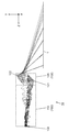
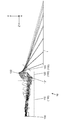
- FIG. 1 is a configuration diagram for explaining an image projection apparatus according to the first to third embodiments.
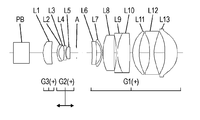
- FIG. 2 is a configuration diagram of a transmission optical system according to the first embodiment (Numerical Example 1).
- FIG. 3 is a configuration diagram of the transmission optical system according to the second embodiment (Numerical Example 2).
- FIG. 4 is a configuration diagram of a transmission optical system according to the third embodiment (Numerical Example 3).
- FIG. 5 is a configuration diagram for explaining an image projection apparatus according to the fourth embodiment.
- FIG. 6 is a schematic diagram illustrating a transmissive element according to the fourth embodiment.
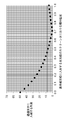
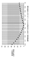
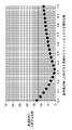
- FIG. 7 is a graph illustrating the relationship between the position of the image on the screen and the angle of light incident on the transmissive element in the fourth embodiment (Numerical Example 4).
- FIG. 4 is a configuration diagram for explaining an image projection apparatus according to the fourth embodiment.
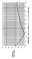
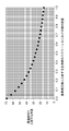
- FIG. 8 is a graph for explaining the relationship between the position of the image on the screen and the angle of light incident on the transmissive element in the fourth embodiment (Numerical Example 5).
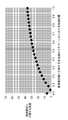
- FIG. 9 is a graph for explaining the relationship between the position of the image on the screen and the angle of light incident on the transmissive element in the fourth embodiment (Numerical Example 6).
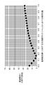
- FIG. 10 is a graph illustrating the relationship between the position of the image on the screen and the angle of light incident on the transmissive element in the fourth embodiment (Numerical Example 7).
- FIG. 11 is a graph illustrating the relationship between the position of the image on the screen and the angle of light incident on the transmissive element in the fourth embodiment (Numerical Example 8).
- FIG. 12 is a graph illustrating the relationship between the position of the image on the screen and the angle of light incident on the transmissive element in the fourth embodiment (Numerical Example 9).
- FIG. 13 is a graph illustrating the relationship between the position of the image on the screen and the angle of light incident on the transmissive element in the fourth embodiment (Numerical Example 10).
- FIG. 14 is a graph illustrating the relationship between the position of the image on the screen and the angle of light incident on the transmissive element in the fourth embodiment (Numerical Example 11).
- FIG. 15 is a graph illustrating the relationship between the position of the image on the screen and the angle of light incident on the transmissive element in the fourth embodiment (Numerical Example 12).
- FIG. 16 is a graph for explaining the relationship between the position of the image on the screen and the angle of light incident on the transmissive element in the fourth embodiment (Numerical Example 13).
- FIG. 17 is a graph for explaining the relationship between the position of the image on the screen and the angle of light incident on the transmissive element in the fourth embodiment (Numerical Example 14).
- FIG. 18 is a graph illustrating the relationship between the position of the image on the screen and the angle of light incident on the transmissive element in the fourth embodiment (Numerical Example 15).
- FIG. 19 is a graph illustrating the relationship between the position of the image on the screen and the angle of light incident on the transmissive element in the fourth embodiment (Numerical Example 16).
- FIG. 20 is a graph illustrating the relationship between the position of the image on the screen and the angle of light incident on the transmissive element in the fourth embodiment (Numerical Example 17).
- FIG. 21 is a graph illustrating the relationship between the position of the image on the screen and the angle of light incident on the transmissive element in the fourth embodiment (Numerical Example 18).
- FIG. 22 is a graph for explaining the relationship between the position of the image on the screen and the angle of light incident on the transmissive element in the fourth embodiment (Numerical Example 19).
- FIG. 23 is a graph illustrating the relationship between the position of the image on the screen and the angle of light incident on the transmissive element in Comparative Example 1.
- FIG. 24 is a graph illustrating the relationship between the position of the image on the screen and the angle of light incident on the transmissive element in Comparative Example 2.
- FIG. 25 is a graph illustrating the relationship between the position of the image on the screen and the angle of light incident on the transmissive element in Comparative Example 3.
- FIG. 26 is a graph illustrating the relationship between the position of the image on the screen and the angle of light incident on the transmissive element in Comparative Example 4.
- the image projection apparatus 10 according to Embodiment 1 is used, for example, in an aircraft cabin.
- the image projection device 10 is disposed in a limited space, such as in the vicinity of a baggage locker, and projects an image on a wall or ceiling in the cabin.
- the image projection apparatus 10 according to the first embodiment can realize a low profile by the configuration of the projection optical system 100, and can reduce image distortion even on a large screen. That is, the image projection apparatus 10 according to the first embodiment is a positive lens (first lens L1, third lens L3, and fifth lens L5) disposed on the image display element 130 side of the aperture stop A of the projection optical system 100. ) Can reduce image distortion. Further, the image projection apparatus 10 according to the first embodiment has a meniscus first positive lens (eleventh lens L11) and negative lens (twelfth lens L12) disposed on the projection plane (screen 1) side of the aperture stop A. ) The meniscus second positive lens (the thirteenth lens L13) can reduce the image distortion even on a large screen while realizing a low profile of the image projection apparatus 10.
- first lens L1, third lens L3, and fifth lens L5 disposed on the image display element 130 side of the aperture stop A of the projection optical system 100.
- the image projection apparatus 10 according to the first embodiment has a meniscus first positive lens (eleventh
- the image projection apparatus 10 includes a projection optical system 100 and an image display element 130.
- the projection optical system 100 includes a positive optical transmission optical system 110 and a reflective optical system 120 as a whole.
- the projection optical system 100 projects the image formed by the image display element 130 onto the screen 1 at a position (an oblique position) that does not face directly.
- the non-facing position means the direction of the normal to the screen 1 at the center of the image projected on the screen 1 and the center of the image among the rays emitted from the final surface of the projection optical system 100. The case where the direction of light does not match.
- the image display element 130 forms a light beam of an image projected on the screen 1 based on the image signal (hereinafter referred to as an image light beam).
- a spatial modulation element such as a DMD (Digital Mirror Device) or a transmissive or reflective liquid crystal panel can be used.
- the display surface of the image display element 130 according to the present disclosure has a long side parallel to the X-axis direction (perpendicular to the paper surface) in FIG. 1 and a short side parallel to the Y-axis direction.
- the transmission optical system 110 includes a prism PB, an aperture stop A, and a first lens L1 to a thirteenth lens L13.
- the prism PB, the aperture stop A, and the first lens L1 to the thirteenth lens L13 are disposed between the image display element 130 and the screen 1.
- the first lens L1 is disposed closest to the image display element 130 among the first lens L1 to the thirteenth lens L13.
- the thirteenth lens L13 is disposed closest to the screen 1 among the first lens L1 to the thirteenth lens L13.
- the first lens L1 to the thirteenth lens L13 are arranged in this order.
- the prism PB is disposed between the first lens L1 and the image display element 130.
- the aperture stop A is disposed between the fifth lens L5 and the sixth lens L6.
- an incident surface a surface on which light from the image display element 130 is incident
- an exit surface is referred to as an output surface.
- the first lens L1 to the fifth lens L5 are arranged closer to the image display element 130 than the aperture stop A.
- the first lens L1 is a meniscus positive power lens.
- the incident surface of the first lens L1 is a convex surface.
- the fact that the incident surface of the transmissive optical system 110 is a convex surface indicates that the convex surface faces the image display element 130 side.
- the second lens L2 is a meniscus negative power lens.
- the incident surface of the second lens is a convex surface.
- the second lens L2 is cemented to the incident surface side of the third lens L3.
- the third lens L3 is a positive power lens.
- the entrance surface and the exit surface of the third lens L3 are convex surfaces.
- the fourth lens L4 is a negative power lens.
- the entrance surface and the exit surface of the fourth lens L4 are concave surfaces.
- the fourth lens L4 is cemented to the emission surface side of the third lens L3.
- the fifth lens L5 is a positive lens having a positive power.
- the entrance surface and the exit surface of the fifth lens L5 are convex surfaces.
- a sixth lens L6 to a thirteenth lens L13 are disposed on the screen 1 side of the aperture stop A.
- the sixth lens L6 is a meniscus positive power lens.
- the exit surface of the sixth lens L6 is a convex surface. That the incident surface of the transmission optical system 110 is a convex surface indicates that the convex surface faces the reflective optical system 120 side.
- the seventh lens L7 is a meniscus negative power lens.
- the exit surface of the seventh lens L7 is a convex surface.
- the eighth lens L8 is a meniscus positive power lens.
- the incident surface of the eighth lens L8 is a convex surface.
- the ninth lens L9 is a negative power lens.
- the entrance surface and the exit surface of the ninth lens L9 are both concave surfaces.
- the tenth lens L10 is a positive power lens.
- the entrance surface and the exit surface of the tenth lens L10 are both convex surfaces.
- the exit surface of the ninth lens L9 and the entrance surface of the tenth lens L10 are cemented, and the ninth lens L9 and the tenth lens L10 constitute a cemented lens.
- the ninth lens L9 a lens having low dispersion is used.
- the ninth lens L9 uses a lens element having the largest Abbe number in the transmission optical system 110.
- the eleventh lens L11 is a meniscus positive power lens.
- the exit surface of the eleventh lens L11 is a concave surface. That is, the concave surface of the eleventh lens L11 faces the reflective optical system 120 side.
- the twelfth lens L12 is a negative power lens.
- the entrance surface and the exit surface of the twelfth lens L12 are both concave surfaces.
- the shape of at least one of the entrance surface and the exit surface of the twelfth lens L12 is preferably an aspherical shape. Specifically, it is desirable that the aspherical surface of the twelfth lens L12 has a shape in which the curvature decreases as the distance from the center of the lens increases in the radial direction. That is, it is desirable that the power on the outside of the lens is smaller than that on the center side of the lens.
- the thirteenth lens L13 is a meniscus positive power lens.
- the incident surface of the thirteenth lens L13 is a concave surface. That is, the concave surface of the thirteenth lens L13 faces the image display element 130 side.
- the shape of the thirteenth lens L13 is the shape having the largest thickness deviation ratio among the meniscus-shaped lenses included in the transmission optical system 110.
- the eleventh lens L11 and the thirteenth lens L13 are arranged so that their concave surfaces face each other.
- a twelfth lens L12 is disposed between the eleventh lens L11 and the thirteenth lens L13.
- At least one of the entrance surface and the exit surface of each of the eleventh lens L11 and the thirteenth lens L13 has an aspheric shape.
- the transmission optical system 110 of Embodiment 1 is focused by two lens groups.
- One lens group includes a second lens L2, a third lens L3, a fourth lens L4, and a fifth lens L5. These second lens L2 to fifth lens L5 are integrated. The distance between the fourth lens L4 and the fifth lens does not change.
- the other lens group includes an eleventh lens L11, a twelfth lens L12, and a thirteenth lens L13. These eleventh lens L11 to thirteenth lens L13 are integrated. The distance between the eleventh lens L11 and the twelfth lens L12 and the distance between the twelfth lens L12 and the thirteenth lens L13 do not change. During focusing, these lens groups move together.
- the reflection optical system 120 reflects the light beam emitted from the transmission optical system 110 and projects it onto the screen 1.
- the reflective optical system 120 includes two mirrors, a first mirror 121 and a second mirror 122.
- the shape of the reflecting surface of the second mirror 122 is a free-form surface.
- the reflection optical system only needs to be composed of one or more mirrors, and the number of mirrors is not limited to two.
- An intermediate image is formed between the transmission optical system 110 and the screen 1.
- an intermediate image is formed by connecting a point where light rays intersect between the exit surface of the thirteenth lens L13 and the reflection surface of the second mirror 122. It is formed.
- the conjugate position between the light beam emitted from the transmission optical system 110 and the second mirror 122 closest to the screen is separated, so that the angle of the light beam incident on the second mirror 122 becomes loose, and the reflection optical system This is advantageous for downsizing.
- positive lenses are arranged closer to the image display element 130 than the aperture stop A.
- the light emitted in the direction perpendicular to the display surface of the image display element 130 can be collected at one point by the aperture stop A. Therefore, the image distortion of the image projected on the screen 1 can be reduced.
- the thirteenth lens L13 can suppress the spread of light rays incident on the first mirror 121. That is, when the light beam incident on the first mirror 121 spreads, it is necessary to enlarge the first mirror 121 on the lower side of the sheet of FIG. 1, and the image projection apparatus 10 may be increased in size.
- the position of the first mirror 121 can be brought as close to the second mirror 122 as possible. Therefore, the image projection apparatus 10 can be reduced in size and height.
- the curvature of field can be corrected with good balance, and image distortion projected on the screen 1 can be corrected. Can be corrected.
- the shape of the thirteenth lens L13 disposed on the screen 1 side with respect to the twelfth lens L12 is the shape having the largest thickness deviation ratio among the meniscus-shaped lenses included in the transmission optical system 110. is there. As a result, the difference in refractive power between the center and the periphery of the thirteenth lens L13 can be increased, which is effective in correcting field curvature.
- the light flux incident on the ninth lens L9 and the tenth lens L10 is increased by the negative meniscus seventh lens L7.
- a low-dispersion lens is used for the ninth lens L9 having negative power among the cemented lenses constituted by the ninth lens L9 and the tenth lens L10. Thereby, lateral chromatic aberration can be favorably corrected.
- the cemented lens including the ninth lens L9 and the tenth lens L10 has a positive refractive power as a whole, and thus can positively correct the positive curvature of field.
- the lens group including the second lens L2 to the fifth lens L5 and the lens group including the eleventh lens L11 to the thirteenth lens L13 are moved together and moved during focusing. Thereby, satisfactory optical performance can be satisfied even if the projection distance changes.
- an intermediate image is formed between the transmission optical system 110 and the screen 1.
- the projection optical system 100 can be reduced in size by using the transmission optical system 110. Further, by using the reflection optical system 120 together, it is possible to deflect light rays steeply. Therefore, even if the distance from the image display element 130 to the screen 1 is short, a large screen can be realized.
- FIGS. 1 and 3 an image projection apparatus 10 according to the second embodiment will be described with reference to FIGS. 1 and 3. Since the basic configuration of the image projection apparatus 10 of the second embodiment is the same as that of the first embodiment, the same reference numerals are given to the same configurations, and description thereof is omitted. Further, since the basic configuration of the first lens L1 to the thirteenth lens L13 is the same as that of the first embodiment, the same reference numerals are given and description thereof is omitted.
- the projection optical system 100 according to Embodiment 2 includes a transmission optical system 110 having a positive power as a whole and a reflection optical system 120.
- the positions of the sixth lens L6, the seventh lens L7, the eighth lens L8, the ninth lens L9, the tenth lens L10, the eleventh lens L11, the twelfth lens L12, and the thirteenth lens L13 are fixed. And the distance between them does not change.
- the transmission optical system 110 of Embodiment 2 is focused by at least one lens group.
- the second lens L2, the third lens L3, the fourth lens L4, and the fifth lens L5 are integrated to form a lens group.
- the second lens L2, the third lens L3, and the fourth lens L4 constitute a cemented lens as in the first embodiment, and the distance between the fourth lens L4 and the fifth lens L5 does not change.
- the lens group constituted by the second lens L2 to the fifth lens L5 moves as a unit to perform focusing. Thereby, good optical performance can be realized even if the projection distance changes.
- the configuration of the projection optical system 100 can realize a reduction in the height of the image projection apparatus 10 and further reduce image distortion even on a large screen.
- Embodiment 3 the image projection apparatus 10 according to Embodiment 3 will be described with reference to FIG. Since the basic configuration of the image projection apparatus 10 of the third embodiment is the same as that of the first embodiment, the same components are denoted by the same reference numerals and description thereof is omitted. Furthermore, since the basic configurations of the first lens L1 to the seventh lens L7, the ninth lens L9, and the eleventh lens L11 to the thirteenth lens L13 are the same as those in the first embodiment, the same reference numerals are given, Description is omitted.
- the projection optical system 100 according to Embodiment 3 includes a transmission optical system 110 having a positive power as a whole and a reflection optical system 120.
- the eighteenth lens L18 in FIG. 4 is used instead of the eighth lens L8 in FIG.
- the eighteenth lens L18 is disposed between the seventh lens L7 and the ninth lens L9.
- the tenth lens L10 is not used. That is, the eleventh lens L11 is disposed on the screen 1 side of the ninth lens L9.
- the transmission optical system 110 includes the first lens L1, the second lens L2, the third lens L3, the fourth lens L4, the fifth lens L5, the first lens L1 between the image display element 130 and the screen 1.
- 6 lens L6, 7th lens L7, 18th lens L18, 9th lens L9, 11th lens L11, 12th lens L12, 13th lens L13, and these lenses are arranged in the above-mentioned order.
- the eighteenth lens L18 is a positive lens having a positive power.
- the entrance surface and the exit surface of the 18th lens L18 are convex surfaces.
- the eighteenth lens L18 and the ninth lens L9 constitute a cemented lens. That is, it is desirable that the exit surface of the 18th lens L18 and the entrance surface of the 9th lens L9 are joined.
- a low-dispersion lens is used as the negative power ninth lens.
- the ninth lens L9 is a lens element having the largest Abbe number in the transmission optical system 110.
- the cemented lens of the eighteenth lens L18 and the ninth lens L9 has a positive refractive power as a whole.
- the transmission optical system 110 is focused by two lens groups.
- One lens group includes a second lens L2 to a fifth lens L5. These second lens L2 to fifth lens L5 are integrated.
- the other lens group includes an eleventh lens L11, a twelfth lens L12, and a thirteenth lens L13. These eleventh lens L11 to thirteenth lens L13 are integrated. During focusing, these lens groups move together. Thereby, satisfactory optical performance can be satisfied even if the projection distance changes.
- the configuration of the projection optical system 100 can realize a reduction in height and can reduce image distortion even on a large screen.
- the luminous flux incident on the eighteenth lens L18 and the ninth lens L9 is increased by the negative meniscus seventh lens L7.
- the low-dispersion lens is used for the negative lens ninth lens L9 among the cemented lenses, the chromatic aberration can be favorably corrected by the cemented lens.
- the cemented lens of the eighteenth lens L18 and the ninth lens L9 has a positive refractive power as a whole, so that positive curvature of field can be corrected well.
- Embodiments 1 to 3 conditions that are preferably satisfied by the projection optical system 100 shown in Embodiments 1 to 3 will be described.
- a plurality of preferable conditions are defined for the projection optical system 100 according to the first to third embodiments, but a configuration that satisfies all of the plurality of conditions is most desirable.
- individual conditions it is possible to obtain a projection optical system that exhibits the corresponding effects.
- the lens (the eleventh lens L11 and the thirteenth lens L13) that are arranged so that their concave surfaces face each other, they are arranged on the image display element 130 side. It is desirable that the lens (the eleventh lens L11) satisfies the following condition (1-1).
- R1 radius of curvature of one surface of the lens disposed on the image display element side
- R2 radius of curvature of the surface opposite to R1 of the lens disposed on the image display element side.
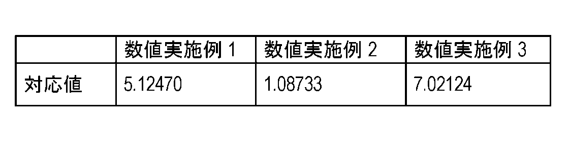
- Table 1 shows corresponding values obtained for the projection optical systems according to Numerical Example 1 to Numerical Example 3. The corresponding value indicates a value of (R2 + R1) / (R2-R1).
- the image projection apparatus 10 includes a transmission optical system 110 having a positive power as a whole, a reflection optical system 120, an image display element 130, and a transmission element 140.
- the transmission optical system 110, the reflection optical system 120, and the transmission element 140 constitute the projection optical system 100 of the fourth embodiment.
- the configurations of the transmission optical system 110, the reflection optical system 120, and the image display element 130 are the same as those of the transmission optical system 110, the reflection optical system 120, and the image display element 130 of the first embodiment, and thus description thereof is omitted. To do.
- the image projection device 10 of the fourth embodiment is applied to the screen 1 at a position where the image (image 131 in FIG. 6) formed by the image display element 130 is not directly opposed.
- the shape of the image 131 formed by the image display element 130 is a rectangle defined by the positive direction of the X axis and the positive direction of the Y axis shown in FIG.
- the image has a long side (long side 131a in FIG. 6) parallel to the X axis and a short side (short side 131b in FIG. 6) parallel to the Y axis.
- the image display element 130 is disposed obliquely above the screen 1 and projects an image from obliquely above.
- the diagonally upward is a position defined in FIG. 5 by the positive direction of the Y axis and the positive direction of the Z axis.
- the transmission element 140 is disposed between the reflection optical system 120 and the screen 1.
- the transmissive element 140 is an optical element that transmits the light beam reflected by the reflective optical system 120 to the screen 1.
- the material of the transmissive element 140 is resin.
- a surface of the transmissive element 140 on which light rays from the image of the image display element 130 are incident is defined as an incident surface.
- a surface of the transmissive element 140 from which light rays from the image of the image display element 130 are emitted is referred to as an emission surface.
- the entrance surface and the exit surface of the transmissive element 140 have a toroidal shape.
- the incident surface of the transmissive element 140 is defined by a long side direction (X-axis direction perpendicular to the paper surface of FIG.
- the transmissive element 140 is a toroidal lens, and the shape of the transmissive element 140 is a shape in which a convex surface is directed to the screen 1 side.
- the curvature in the long side direction (X axis direction) of the image display element 130 on the incident surface of the transmissive element 140 is larger than the curvature in the direction corresponding to the short side direction (Y axis direction).
- the curvature in the long side direction (X-axis direction) of the image display element 130 on the exit surface of the transmissive element 140 is larger than the curvature in the direction corresponding to the short side direction (Y-axis direction).
- An image displayed by the image display element 130 is referred to as an image 131.
- a light ray emitted from the image 131 and passing through the center of the pupil of the transmission optical system 110 is referred to as a principal ray L.
- a position on the incident surface of the transmissive element 140 through which the principal ray L emitted from the center O of the image 131 passes is defined as a reference intersection point BO.
- An intersection line that passes through the reference intersection BO and is parallel to a direction corresponding to a direction (Y-axis direction) parallel to the short side 131b of the image 131 is defined as a reference longitudinal intersection line BL.
- the principal ray L incident on the reference longitudinal intersection line BL includes a ray parallel to the normal line at the reference intersection point BO.
- the principal ray L incident on the reference longitudinal line of the transmission element 140 includes a ray parallel to the normal line at the reference intersection BO.
- the incident angle can be reduced (however, the incident angle of the principal ray L parallel to the normal is set to 0 degree).
- the reflection of the principal ray L at the transmissive element 140 can be suppressed.
- transmits the transmissive element 140 can be suppressed.
- the above effect is more effective.
- the transmissive element 140 is desirably arranged so as to satisfy the following conditional expression (2).
- Yp In an image projected on the screen 1 (hereinafter referred to as a projected image), the position of an arbitrary point on a straight line passing through the center of the projected image and parallel to the short side of the projected image is the positive direction of the Y axis of the image 131 Is a relative position on the screen 1 at which a principal ray L that passes through the reference longitudinal intersection line BL and is parallel to the normal line at the reference intersection point BO reaches the relative direction on the screen 1.
- the relative position Yp will be specifically described.
- the position of the light ray that enters the position closest to the final exit surface of the projection optical system 100 (the exit surface of the transmission element 140 in the fourth embodiment) is set to zero.
- the position of the light ray that enters the position farthest from the final exit surface of the projection optical system 100 is assumed to be 1.
- the position on the screen 1 where the principal ray L emitted from the lowest position (point 0) reaches in the positive direction of the Y axis in FIG. “0”.
- the position on the screen 1 at which the principal ray L emitted from the uppermost position in the positive direction of the Y axis reaches “1”.
- the incident angle of the entire principal ray L with respect to the transmissive element 140 can be kept small. That is, the attenuation of the light amount of the chief ray L emitted from the end portion of the image 131 can be suppressed. Therefore, the uniformity of the luminance distribution of the projection image projected on the screen 1 can be improved.
- the transmissive element 140 can be disposed in an opening provided in the housing of the image projection apparatus 10.
- the opening allows the light beam to pass therethrough.
- a cover glass may be disposed in the opening so that dust, dust, and the like do not enter the housing of the image projection apparatus 10 from the opening. Therefore, the transmissive element 140 can be used as a cover glass.
- Table 2 shows the relative position Yp in the projection optical system 100 of Numerical Example 4 to Numerical Example 11.
- Table 3 shows the relative position Yp in the projection optical system 100 of Numerical Example 12 to Numerical Example 19.
- the curvature of the incident surface of the transmissive element 140 in the direction perpendicular to the reference longitudinal line BL is larger than the curvature in the direction parallel to the reference longitudinal line BL.
- the principal ray L incident on the reference longitudinal line BL has a ray parallel to the normal line of the incident surface of the transmissive element 140 at the reference intersection BO.
- both the incident surface and the reflecting surface of the transmissive element 140 are toroidal surfaces, but at least one of the incident surface and the reflecting surface may be a surface having different curvatures in two orthogonal directions. That's fine.
- at least one of the incident surface and the reflective surface of the transmissive element 140 may be a free-form surface.
- the reflective optical system 120 of Embodiment 4 has the 1st mirror 121 and the 2nd mirror 122, it does not need to have the 1st mirror 121, for example. That is, the reflection optical system 120 may be configured only by the second mirror 122 whose reflection surface is a free-form concave surface.
- the first mirror 121 having a flat reflecting surface is disposed at a position closer to the image display element 130 than the second mirror 122 having a concave reflecting surface. That is, the second mirror 122 may be disposed at a position closer to the image display element 130 than the first mirror 121.
- the projection optical system 100 according to the fourth embodiment includes the reflective optical system 120, the reflective optical system 120 may not be included.
- the material of the transmissive element 140 of Embodiment 4 is resin, it is easy to process a toroidal surface and a free-form surface.
- the material of the transmissive element 140 may be a material other than resin, for example, glass.
- the unit of length in the table is “mm”, and the unit of angle of view is “°”.
- r is a radius of curvature
- d is a surface interval
- nd is a refractive index with respect to the d line
- vd is an Abbe number with respect to the d line.
- the surface marked with * is an aspherical surface, and the aspherical shape is defined by the following equation.
- Z distance from a point on the aspheric surface having a height h from the optical axis to the tangent plane of the aspheric vertex
- h height from the optical axis
- r vertex radius of curvature
- ⁇ conic constant
- An n-order aspherical coefficient.
- the lens constituent length is the distance from the first surface to the end surface
- the front principal point position is the distance from the first surface
- the rear principal point position is the distance from the first surface.
- the surface number 1 of data 1 indicates the incident surface of the prism PB in FIG. 2, and the surface number 2 indicates the exit surface of the prism PB.
- the surface with surface number 3 indicates the entrance surface of the first lens L1, and the surface with surface number 4 indicates the exit surface of the first lens L1.
- the surface number 5 is the incident surface of the second lens L2, the surface number 6 is the cemented surface of the second lens L2 and the third lens L3, and the surface number 7 is the cemented surface of the third lens L3 and the fourth lens L4.
- Surface, surface number 8 indicates the exit surface of the fourth lens L4.
- the surface with surface number 9 indicates the entrance surface of the fifth lens L5, and the surface with surface number 10 indicates the exit surface of the fifth lens L5.
- the surface with surface number 11 represents the aperture stop A.
- the surface with surface number 12 is the entrance surface of the sixth lens L6, and the surface with surface number 13 is the exit surface of the sixth lens L6.
- the surface with surface number 14 is the entrance surface of the seventh lens L7, and the surface with surface number 15 is the exit surface of the seventh lens L7.
- the surface with surface number 16 indicates the entrance surface of the eighth lens L8, and the surface with surface number 17 indicates the exit surface of the eighth lens L8.
- the surface number 18 indicates the entrance surface of the ninth lens L9, the surface number 19 indicates the cemented surface of the ninth lens L9 and the tenth lens L10, and the surface number 20 indicates the exit surface of the tenth lens L10.
- the surface with surface number 21 indicates the entrance surface of the eleventh lens L11, and the surface with surface number 22 indicates the exit surface of the eleventh lens L11.
- the surface number 23 indicates the entrance surface of the twelfth lens L12, and the surface number 24 indicates the exit surface of the twelfth lens L12.
- the surface with surface number 25 indicates the entrance surface of the thirteenth lens L13, and the surface with surface number 26 indicates the exit surface of the thirteenth lens L13.
- Lens 4 in data 4 corresponds to prism PB, and lenses 2 to 14 correspond to first lens L1 to thirteenth lens L13, respectively.
- the lens group 1 of the data 5 is the first lens L1
- the lens group 2 is the second lens L2 to the fifth lens L5
- the lens group 3 is the sixth lens L6 to the tenth lens L10
- the lens group 4 is the eleventh lens L11 to Lth. It corresponds to 13 lens L13.
- the surface number of data 6 indicates the same surface as the surface number of data 1.
- the lens number of data 9 indicates the same lens as the lens number of data 4.
- Data 6 Surface data Surface number r d nd vd Effective diameter Image display element ⁇ 1 ⁇ 15.00000 1.51680 64.2 2 ⁇ 12.66300 3 * 17.19300 8.00000 1.59349 67.0 4 * 290.32200 5.10600 12.510 5 14.48000 1.50000 2.00069 25.5 6 8.78200 5.08500 1.49700 81.6 7 -32.37200 1.50000 1.90366 31.3 8 19.67100 0.50000 9 17.21600 3.54300 1.84666 23.8 4.696 10 -122.74800 6.15600 11 (Aperture) ⁇ 14.49 800 4.330 12 -93.48000 4.07700 1.78472 25.7 13 -52.70900 4.39600 14 -13.56800 1.00000 1.91082 35.2 15 -19.77000 0.50000 16 40.73100 10.43500 1.72342 38.0 17 973.57600 1.96300 18 -77.44100 1.20000 1.49700 81.6 19
- Surface number 1 to surface number 15 in data 10 indicate the same surface as surface number 1 to surface number 15 in data 1.
- the surface number 16 of the data 10 is the entrance surface of the 18th lens L18
- the surface number 17 is the cemented surface of the 18th lens L18 and the 9th lens L9
- the surface number 18 is the exit surface of the 9th lens L9.
- Surface number 19 indicates the entrance surface of the eleventh lens L11
- surface number 20 indicates the exit surface of the eleventh lens L11.
- Surface number 21 indicates the entrance surface of the twelfth lens L12
- surface number 22 indicates the exit surface of the twelfth lens L12.
- Surface number 23 indicates the entrance surface of the thirteenth lens L13
- surface number 24 indicates the exit surface of the thirteenth lens L13.
- the surface number of data 11 and the surface number of data 10 are the same.
- the lens 1 corresponds to the prism PB
- the lenses 2 to 8 correspond to the first lens L1 to the seventh lens L7.
- the lens 9 corresponds to the eighteenth lens L18.
- the lens 10 corresponds to the ninth lens L9.
- the lenses 11 to 13 correspond to the eleventh lens L11 to the thirteenth lens L13.
- the lens group 1 of the data 14 is the first lens L1
- the lens group 2 is the second lens L2 to the fifth lens L5
- the lens group 3 is the sixth lens L6, the seventh lens L7, the eighteenth lens L18, and the ninth lens L9. It corresponds to.
- the lens group 4 corresponds to the eleventh lens L11 to the thirteenth lens L13.
- the transmission optical system 110 of Numerical Example 12 to Numerical Example 19 corresponds to the transmission optical system 110 of the modification of the fourth embodiment.
- the transmissive element 140 is disposed between the reflective optical system 120 and the screen 1.
- the surface number 1 of the data 15 indicates the incident surface of the transmissive element 140.
- Surface number 2 indicates the exit surface of the transmissive element 140.
- [Data 15] Surface data surface number X radius of curvature Y radius of curvature d Nd Vd 1 -198 ⁇ 2.0 1.5168 64.2 2 -200 ⁇ (Numerical example 4)
- the transmissive element 140 is disposed at an angle of 70 degrees with respect to the direction orthogonal to the display surface of the image display element 130.
- the vertical axis of the graph in FIG. 7 indicates the angle (incident angle) of the principal ray L incident on the reference longitudinal line BL of the transmissive element 140.
- the horizontal axis of the graph in FIG. 7 indicates the relative position (Yp) on the screen 1 of the principal ray L incident on the reference longitudinal line BL.
- the position where the relative position is 0 indicates the position of the principal ray L incident on the position closest to the final exit surface of the projection optical system 100 in the projected image projected on the screen 1.
- the position where the relative position is 1 indicates the position of the light ray incident on the position farthest from the final exit surface of the projection optical system 100 in the projected image projected on the screen 1.
- the position on the screen 1 where the light ray emitted from the bottom in the Y-axis direction of FIG. 5 arrives is 0, and on the screen 1 where the light ray emitted from the top reaches The position of becomes 1.
- the angle at which the principal ray L reaching the relative position 0.7 on the screen 1 is incident on the reference longitudinal line BL of the transmissive element 140 is zero. It can also be seen that the largest angle among the incident angles of the principal ray L incident on the reference longitudinal line BL is 50 degrees.
- lens data of the transmission optical system 110 in the numerical examples 8, 9, 10 and 11 is the same as that in the numerical example 1, description thereof is omitted.
- the following data 16 shows lens data of the transmissive element 140 of Numerical Examples 8, 9, 10 and 11.
- the surface number 1 of the data 16 indicates the incident surface of the transmissive element 140.
- Surface number 2 indicates the exit surface of the transmissive element 140.
- [Data 16] Surface data surface number X radius of curvature Y radius of curvature d Nd Vd 1 -248 -298 2.0 1.5168 64.2 2 -250 -300 (Numerical example 8)
- the transmissive element 140 is disposed at an angle of 70 degrees with respect to the direction orthogonal to the surface of the image display element 130.
- the angle at which the principal ray L reaching the relative position 0.8 on the screen 1 is incident on the reference longitudinal line BL of the transmission element 140 becomes zero.
- the largest angle among the incident angles of the principal ray L incident on the reference longitudinal line BL is 47 degrees.
- Numerical examples 12 to 15 correspond to modifications of the fourth embodiment. Since the lens data of the transmission optical system 110 in Numerical Examples 12 to 15 is the same as that of Numerical Example 1, the description thereof is omitted. Data 17 below shows lens data of the transmissive element 140 of Numerical Examples 12 to 15.
- the surface number 1 of the data 17 indicates the incident surface of the transmissive element 140.
- Surface number 2 indicates the exit surface of the transmissive element 140.
- [Data 17] Surface data surface number X radius of curvature Y radius of curvature d Nd Vd 1 -113 ⁇ 2.0 1.5168 64.2 2 -115 ⁇
- the arrangement positions of the first mirror 121 and the second mirror 122 are reversed. That is, the second mirror 122 whose reflection surface is a free-form surface is arranged at a position closer to the image display element 130 than the first mirror 121 whose reflection surface is a plane.
- Numerical examples 16 to 19 correspond to modifications of the fourth embodiment. Since the lens data of the transmission optical system 110 in Numerical Examples 16 to 19 is the same as that in Numerical Example 1, description thereof is omitted. Data 18 below shows lens data of the transmissive element 140 of Numerical Examples 16 to 19.
- the surface number 1 of the data 18 indicates the incident surface of the transmissive element 140.
- Surface number 2 indicates the exit surface of the transmissive element 140.
- [Data 18] Surface data surface number X radius of curvature Y radius of curvature d Nd Vd 1 -113 ⁇ 2.0 1.5168 64.2 2 -115 ⁇ In the following numerical examples 16, 17, 18 and 19, only the second mirror 122 was used without using the first mirror 121 which is a plane mirror.
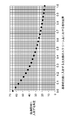
- Comparative Example 1 In order to compare with Numerical Examples 4, 5, 6, and 7, in Comparative Example 1, the transmissive element 140 was disposed at an angle of 90 degrees with respect to the direction orthogonal to the surface of the image display element 130. Other configurations of the projection optical system 100 of Comparative Example 1 are the same as those of Numerical Examples 4, 5, 6, and 7. As a result, as shown in FIG. 23, in Comparative Example 1, the angle at which the principal ray L that reaches the screen 1 is incident on the reference longitudinal ray BL of the transmissive element 140 does not become zero. Therefore, it can be seen that the largest angle among the principal rays L incident on the reference longitudinal line BL is 70 degrees, which is larger than those in the numerical examples 4, 5, 6 and 7.
- Comparative Example 2 In order to compare with Numerical Examples 8, 9, 10, and 11, in Comparative Example 2, the transmissive element 140 was disposed at an angle of 90 degrees with respect to the direction orthogonal to the surface of the image display element 130.
- Other configurations of the projection optical system 100 of the comparative example 2 are the same as those of the numerical examples 8, 9, 10 and 11.
- the angle at which the principal ray L reaching the screen 1 is incident on the reference longitudinal ray BL of the transmissive element 140 does not become zero. Therefore, it can be seen that the largest angle among the principal rays L incident on the reference longitudinal line BL is 66 degrees, which is larger than those in the numerical examples 8, 9, 10 and 11.
- Comparative Example 4 In order to compare with Numerical Examples 16, 17, 18, and 19, in Comparative Example 4, the transmissive element 140 was disposed at an angle of 90 degrees with respect to the direction orthogonal to the surface of the image display element 130.
- the other configuration of the projection optical system 100 of Comparative Example 4 is the same as that of Numerical Examples 16, 17, 18, and 19.
- the angle at which the principal ray L reaching the screen 1 is incident on the reference longitudinal line BL of the transmissive element 140 does not become zero. Therefore, it can be seen that the largest angle among the principal rays L incident on the reference longitudinal line BL is 46 degrees, which is larger than those in the numerical examples 16, 17, 18, and 19.
- the first to fourth embodiments have been described as examples of the technology disclosed in the present application.
- the technology in the present disclosure is not limited to this, and can also be applied to embodiments that have been changed, replaced, added, omitted, and the like. Further, it is possible to combine the components described in the first to fourth embodiments to form a new embodiment.
- the present disclosure is applicable to projection for projecting an image displayed on an image display element. Specifically, the present disclosure is applicable to a projector, a head-up display, and the like.
Landscapes
- Physics & Mathematics (AREA)
- General Physics & Mathematics (AREA)
- Optics & Photonics (AREA)
- Lenses (AREA)
- Projection Apparatus (AREA)
Abstract
画像を斜めの位置から、投写面(1)に拡大して投写する投写光学系(100)であって、透過光学系(110)と、透過素子(140)とを備える。透過光学系(110)は、レンズ素子を含み、画像表示素子(130)が表示する画像を拡大する。透過素子(140)は、透過光学系(110)と投写面(1)との間の光路上に配置され、画像の光線を遮蔽することなく透過する。透過素子(140)の入射面及び出射面の少なくとも一方の面において、画像から出射して透過光学系(110)の瞳の中心を通る主光線のうち、画像の中心から出射する光線が通過する点を基準交点とし、基準交点を通り、Y軸の正の方向に対応する方向と平行な線を基準縦交線とする。透過素子(140)の一方の面の、基準縦交線と垂直な方向に対する曲率は、基準縦交線と平行な方向に対する曲率よりも大きい。主光線のうち、基準縦交線に入射する光線は、基準交点における一方の面の法線と平行になる光線を有する。
Description
本開示は、投写光学系および投写光学系を備える画像投写装置に関する。
特許文献1は、反射面を含む投写光学系を用いた投写装置を開示する。この投写装置は、ライトバルブに形成された画像を投影面に拡大投影するための投写光学系である。投写光学系は、複数のレンズからなり、投影面とライトバルブとの間に、画像の中間像を形成するための正のパワーを有するレンズ光学系と、中間像を結像した後の発散する光束を反射し、投影面上に結像させるための正のパワーを有する第1反射面と、レンズ光学系からの射出光を第1反射面に入射させるための第2反射面と、からなる。これにより、色収差および歪みが低減された大画面を投写することができる。
本開示における投写光学系は、XYZ座標を用いて位置関係を表す場合に、画像表示素子に表示され、X軸の正の方向及びY軸の正の方向で定義され、X軸に平行な長辺とY軸に平行な短辺とを有する画像を、Y軸とZ軸とで定義される斜めの位置から、投写面に拡大して投写する。投写光学系は、透過光学系と透過素子とを備える。透過光学系は、レンズ素子を含み、画像表示素子が表示する画像を拡大する。透過素子は、透過光学系と投写面との間の光路上に配置され、画像の光線を遮蔽することなく透過する。透過素子の、光線が入射する入射面及び光線が出射する出射面の少なくとも一方の面において、画像から出射して透過光学系の瞳の中心を通る主光線のうち、画像の中心から出射する光線が通過する点を基準交点とし、基準交点を通り、Y軸の正の方向に対応する方向と平行な線を基準縦交線とするとき、一方の面の、基準縦交線と垂直な方向に対する曲率は、基準縦交線と平行な方向に対する曲率よりも大きく、主光線のうち、基準縦交線に入射する光線は、基準交点における一方の面の法線と平行になる光線を有する。
本開示の画像投写装置は、XYZ座標を用いて位置関係を表す場合に、画像をY軸及びZ軸で定義される斜めの位置から投写面に拡大して投写する。画像投写装置は、画像表示素子と、透過光学系と、透過素子と、を備える。画像表示素子は、X軸の正の方向及びY軸の正の方向で定義され、X軸に平行な長辺とY軸に平行な短辺とを有する、画像を表示する。透過光学系は、レンズ素子を含み、画像を拡大する。透過素子は、透過光学系と投写面との間の光路上に配置され、画像の光線を遮蔽することなく透過する。透過素子の、画像からの光線が入射する入射面及び光線が出射する出射面の少なくとも一方の面において、画像から出射して透過光学系の瞳の中心を通る主光線のうち、画像の中心から出射する光線が通過する点を基準交点とし、基準交点を通り、Y軸の正の方向に対応する方向と平行な線を基準縦交線とするとき、一方の面の、基準縦交線と垂直な方向に対する曲率は、基準縦交線と平行な方向に対する曲率よりも大きく、主光線のうち、基準縦交線に入射する光線は、基準交点における一方の面の法線と平行になる光線を有する。
本開示における投写光学系によれば、投写面に投影される画像の輝度分布の均一性を向上できる。
以下、適宜図面を参照しながら、実施の形態を詳細に説明する。但し、必要以上に詳細な説明は省略する場合がある。例えば、既によく知られた事項の詳細説明や実質的に同一の構成に対する重複説明を省略する場合がある。これは、以下の説明が不必要に冗長になるのを避け、当業者の理解を容易にするためである。
なお、添付図面および以下の説明は、当業者が本開示を十分に理解するために、提供されるのであって、これらにより請求の範囲に記載の主題を限定することは意図されていない。
(実施の形態1)
以下、実施の形態1に係る画像投写装置10を図1及び図2を用いて説明する。
以下、実施の形態1に係る画像投写装置10を図1及び図2を用いて説明する。
実施の形態1の画像投写装置10は、たとえば航空機の客室内で用いられる。画像投写装置10は、たとえば手荷物用のロッカーの近傍など、限られたスペースに配置され、客室内の壁や天井に画像を投写する。
実施の形態1の画像投写装置10は、投写光学系100の構成により低背化を実現でき、さらに大画面でも画像歪みを低減できる。すなわち実施の形態1の画像投写装置10は、投写光学系100の、開口絞りAよりも画像表示素子130側に配置された正レンズ(第1レンズL1、第3レンズL3、及び第5レンズL5)により、画像歪みを低減できる。また実施の形態1の画像投写装置10は、開口絞りAよりも投写面(スクリーン1)側に配置された、メニスカス形状の第1正レンズ(第11レンズL11)、負レンズ(第12レンズL12)、メニスカス形状の第2正レンズ(第13レンズL13)により、画像投写装置10の低背化を実現しつつ、大画面でも画像歪みを低減できる。
[1-1.構成]
図1に示すように、実施の形態1に係る画像投写装置10は、投写光学系100と画像表示素子130とから構成される。投写光学系100は、全体として正のパワーの透過光学系110と、反射光学系120とを備える。投写光学系100は、画像表示素子130で形成された画像を、正対しない位置(斜めの位置)にあるスクリーン1に投写する。ここで、正対しない位置とは、スクリーン1上に投写される画像の中心における、スクリーン1に対する法線の方向と、投写光学系100の最終面から出射する光線の内、画像の中心を通る光の方向とが一致しない場合を言う。
図1に示すように、実施の形態1に係る画像投写装置10は、投写光学系100と画像表示素子130とから構成される。投写光学系100は、全体として正のパワーの透過光学系110と、反射光学系120とを備える。投写光学系100は、画像表示素子130で形成された画像を、正対しない位置(斜めの位置)にあるスクリーン1に投写する。ここで、正対しない位置とは、スクリーン1上に投写される画像の中心における、スクリーン1に対する法線の方向と、投写光学系100の最終面から出射する光線の内、画像の中心を通る光の方向とが一致しない場合を言う。
画像表示素子130は、画像信号を基にスクリーン1に投写する画像の光束(以下、画像光束という)を形成する。画像表示素子としては、DMD(Degital Mirror Device)や透過型や反射型の液晶パネル等の空間変調素子を用いることができる。本開示における画像表示素子130の表示面は、図1のX軸方向(紙面垂直方向)に平行な長辺と、Y軸方向に平行な短辺とを有する。
図2に示すように、透過光学系110は、プリズムPBと、開口絞りAと、第1レンズL1~第13レンズL13と、を有する。プリズムPBと、開口絞りAと、第1レンズL1~第13レンズL13とは、画像表示素子130とスクリーン1との間に配置される。
第1レンズL1は、第1レンズL1~第13レンズL13のうち最も画像表示素子130側に配置される。第13レンズL13は、第1レンズL1~第13レンズL13のうち最もスクリーン1側に配置される。第1レンズL1~第13レンズL13は、この順に配置される。
プリズムPBは第1レンズL1と画像表示素子130との間に配置される。開口絞りAは第5レンズL5と第6レンズL6との間に配置される。
以下、第1レンズL1~第13レンズL13について説明する。以下、画像表示素子130からの光が入射する面を入射面とし、出射する面を出射面とする。
第1レンズL1~第5レンズL5は、開口絞りAよりも画像表示素子130側に配置されている。
第1レンズL1は、メニスカス形状の正のパワーのレンズである。第1レンズL1の入射面は凸面である。透過光学系110の入射面が凸面であることは、その凸面は画像表示素子130側を向いていることを示す。
第2レンズL2は、メニスカス形状の負のパワーのレンズである。第2レンズの入射面は、凸面である。第2レンズL2は、第3レンズL3の入射面側に接合されている。
第3レンズL3は、正のパワーのレンズである。第3レンズL3の入射面及び出射面は、凸面である。
第4レンズL4は、負のパワーのレンズである。第4レンズL4の入射面及び出射面は、凹面である。第4レンズL4は、第3レンズL3の出射面側に接合されている。
第5レンズL5は、正のパワーを持つ正レンズである。第5レンズL5の入射面及び出射面は凸面である。
開口絞りAよりもスクリーン1側には、第6レンズL6~第13レンズL13が配置されている。
第6レンズL6は、メニスカス形状の正のパワーのレンズである。第6レンズL6の出射面は凸面である。透過光学系110入射面が凸面であることは、その凸面は反射光学系120側を向いていることを示す。
第7レンズL7は、メニスカス形状の負のパワーのレンズである。第7レンズL7の出射面は凸面である。
第8レンズL8は、メニスカス形状の正のパワーのレンズである。第8レンズL8の入射面は凸面である。
第9レンズL9は、負のパワーのレンズである。第9レンズL9の入射面及び出射面は、いずれも凹面である。
第10レンズL10は、正のパワーのレンズである。第10レンズL10の入射面及び出射面は、いずれも凸面である。
第9レンズL9の出射面と第10レンズL10の入射面は接合され、第9レンズL9と第10レンズL10とで接合レンズを構成していることが望ましい。第9レンズL9には低分散性を有するレンズを用いている。本実施の形態では、第9レンズL9は、透過光学系110で最もアッベ数の大きいレンズ素子を用いている。
第11レンズL11は、メニスカス形状の正のパワーのレンズである。第11レンズL11の出射面は、凹面である。つまり第11レンズL11の凹面は、反射光学系120側を向いている。
第12レンズL12は、負のパワーのレンズである。第12レンズL12の入射面及び出射面は、いずれも凹面である。この第12レンズL12の入射面及び出射面の少なくとも一方の形状は、非球面形状であることが望ましい。具体的には、第12レンズL12の非球面形状を有する面は、レンズの中心から径方向に離れるに従って、曲率が小さくなる形状を有することが望ましい。すなわち、レンズの中心側に比べてレンズの外側のパワーが小さくなっていることが望ましい。
第13レンズL13は、メニスカス形状の正のパワーのレンズである。第13レンズL13の入射面は凹面である。つまり第13レンズL13の凹面は画像表示素子130側を向いている。第13レンズL13の形状は、透過光学系110に含まれるメニスカス形状のレンズの中で、最も偏肉比が大きい形状である。
第11レンズL11と第13レンズL13とは、互いの凹面を向かい合わせるように配置される。第11レンズL11と第13レンズL13との間には、第12レンズL12が配置される。
第11レンズL11及び第13レンズL13のそれぞれの入射面及び出射面のうち、少なくとも1つの面は、非球面形状を有することが望ましい。
実施の形態1の透過光学系110は、2つのレンズ群でフォーカスしている。一つのレンズ群は、第2レンズL2と、第3レンズL3と、第4レンズL4と、第5レンズL5とを有する。これらの第2レンズL2~第5レンズL5は一体である。第4レンズL4と第5レンズとの間の間隔は変化しない。他のレンズ群は、第11レンズL11と、第12レンズL12と、第13レンズL13とを有する。これらの第11レンズL11~第13レンズL13は一体である。第11レンズL11と第12レンズL12との間隔と、第12レンズL12と第13レンズL13との間隔は変化しない。フォーカシングの際、これらのレンズ群がそれぞれ一体で移動する。
反射光学系120は、透過光学系110が出射する光束を反射し、スクリーン1に投写する。反射光学系120は、第1ミラー121と第2ミラー122の2枚のミラーで構成される。第2ミラー122の反射面の形状は、自由曲面形状である。なお、反射光学系は、1枚以上のミラーから構成されればよく、ミラーの数は2枚に限定されるものではない。
透過光学系110とスクリーン1との間に中間像が結像される。図1および図2を用いて説明すると、たとえば実施の形態1では、第13レンズL13の出射面と第2ミラー122の反射面との間において、光線が交差する点を結ぶと、中間像が形成される。中間像を形成することで、透過光学系110から射出された光線と最もスクリーン側の第2ミラー122との共役位置が離れるため、第2ミラー122に入射する光線角度が緩くなり、反射光学系の小型化に有利である。
[1-2.効果]
実施の形態1の画像投写装置10では、開口絞りAよりも画像表示素子130側に正のレンズ(第1レンズL1、第3レンズL3、及び第5レンズL5)が配置されている。これらの正のレンズにより、画像表示素子130の表示面に対し垂直な方向に出射する光線を、開口絞りAで一点に集めることができる。したがって、スクリーン1に投写される画像の画像歪みを低減できる。
実施の形態1の画像投写装置10では、開口絞りAよりも画像表示素子130側に正のレンズ(第1レンズL1、第3レンズL3、及び第5レンズL5)が配置されている。これらの正のレンズにより、画像表示素子130の表示面に対し垂直な方向に出射する光線を、開口絞りAで一点に集めることができる。したがって、スクリーン1に投写される画像の画像歪みを低減できる。
実施の形態1の画像投写装置10では、第13レンズL13により、第1ミラー121に入射する光線の広がりを抑制できる。すなわち、第1ミラー121に入射する光線が広がると、第1ミラー121を図1の紙面上の下方で大きくする必要があり、画像投写装置10が大型化してしまう場合がある。実施の形態1では、第13レンズL13により光線の広がりを抑制できるため、第1ミラー121の位置をできるだけ第2ミラー122に近づけることができる。したがって、画像投写装置10の小型化かつ低背化を実現できる。
実施の形態1の画像投写装置10では、第11レンズL11、第12レンズL12及び第13レンズL13を用いることにより、像面湾曲を良好にバランスよく補正でき、スクリーン1に投写される画像歪みを補正できる。
実施の形態1では、第12レンズL12よりもスクリーン1側に配置される第13レンズL13の形状は、透過光学系110に含まれるメニスカス形状のレンズの中で、最も偏肉比が大きい形状である。これにより、第13レンズL13の中心と周辺での屈折力差が大きくできるため、像面湾曲の補正に有効である。
実施の形態1では、第9レンズL9及び第10レンズL10に入射する光束は、負のメニスカス形状の第7レンズL7によって大きくなっている。そして実施の形態1では、第9レンズL9及び第10レンズL10で構成される接合レンズの内、負のパワーの第9レンズL9に低分散レンズを用いている。これにより倍率色収差を良好に補正できる。なお、第9レンズL9及び第10レンズL10で構成される接合レンズは、全体として正の屈折力を有することで正の像面湾曲を良好に補正できる。
実施の形態1では、第2レンズL2~第5レンズL5からなるレンズ群と第11レンズL11~第13レンズL13からなるレンズ群が一体でそれぞれ移動し、フォーカシングの際に移動する。これにより、投写距離が変わっても良好な光学性能を満足できる。
実施の形態1では、透過光学系110とスクリーン1との間には中間像が形成される。これにより第1ミラー121及び第2ミラー122で反射させた画像の歪みが少なくなり、大画面化できる。すなわち画像表示素子130からスクリーン1までの距離が短くても、大画面化を実現できる。
実施の形態1では、透過光学系110を用いることで投写光学系100を小型化できる。さらに反射光学系120を併用することで、光線を急峻に偏向させることができる。したがって、画像表示素子130からスクリーン1までの距離が短くても、大画面化を実現できる。
(実施の形態2)
以下、実施の形態2に係る画像投写装置10を図1及び図3を用いて説明する。実施の形態2の画像投写装置10の基本的な構成は、実施の形態1と同様であるため、同様の構成については同じ符号を付し、説明を省略する。さらに第1レンズL1~第13レンズL13の基本的な構成については、実施の形態1と同様であるため、同じ符号を付し、説明を省略する。
以下、実施の形態2に係る画像投写装置10を図1及び図3を用いて説明する。実施の形態2の画像投写装置10の基本的な構成は、実施の形態1と同様であるため、同様の構成については同じ符号を付し、説明を省略する。さらに第1レンズL1~第13レンズL13の基本的な構成については、実施の形態1と同様であるため、同じ符号を付し、説明を省略する。
[2-1.構成]
実施の形態2に係る投写光学系100は、全体として正のパワーの透過光学系110と、反射光学系120とを備える。
実施の形態2に係る投写光学系100は、全体として正のパワーの透過光学系110と、反射光学系120とを備える。
実施の形態2では、第6レンズL6、第7レンズL7、第8レンズL8、第9レンズL9、第10レンズL10、第11レンズL11、第12レンズL12、及び第13レンズL13の位置は固定であり、互いの間隔は変化しない。
実施の形態2の透過光学系110は、少なくとも一つのレンズ群でフォーカスすることが好ましい。たとえば、第2レンズL2、第3レンズL3、第4レンズL4、及び第5レンズL5が一体となり、レンズ群を構成する。第2レンズL2、第3レンズL3、及び第4レンズL4は、実施の形態1と同様に接合レンズを構成し、第4レンズL4と第5レンズL5との間隔は変化しない。これらの第2レンズL2~第5レンズL5で構成されたレンズ群が一体で移動し、フォーカシングを行うことが望ましい。これにより投写距離が変わっても良好な光学性能を実現できる。
[2-2.効果]
実施の形態2では、実施の形態1と同様に、投写光学系100の構成により、画像投写装置10の低背化を実現でき、さらに大画面でも画像歪みを低減できる。
実施の形態2では、実施の形態1と同様に、投写光学系100の構成により、画像投写装置10の低背化を実現でき、さらに大画面でも画像歪みを低減できる。
(実施の形態3)
以下、実施の形態3に係る画像投写装置10を、図4を用いて説明する。実施の形態3の画像投写装置10の基本的な構成は、実施の形態1と同様であるため、同様の構成については同じ符号を付し、説明を省略する。さらに第1レンズL1~第7レンズL7、第9レンズL9、及び第11レンズL11~第13レンズL13の基本的な構成については、実施の形態1と同様であるため、同じ符号を付し、説明を省略する。
以下、実施の形態3に係る画像投写装置10を、図4を用いて説明する。実施の形態3の画像投写装置10の基本的な構成は、実施の形態1と同様であるため、同様の構成については同じ符号を付し、説明を省略する。さらに第1レンズL1~第7レンズL7、第9レンズL9、及び第11レンズL11~第13レンズL13の基本的な構成については、実施の形態1と同様であるため、同じ符号を付し、説明を省略する。
[3-1.構成]
実施の形態3に係る投写光学系100は、全体として正のパワーの透過光学系110と、反射光学系120と、を備える。
実施の形態3に係る投写光学系100は、全体として正のパワーの透過光学系110と、反射光学系120と、を備える。
実施の形態3では、実施の形態1と異なり、図2の第8レンズL8に代えて図4の第18レンズL18を用いている。すなわち第18レンズL18は、第7レンズL7と第9レンズL9との間に配置されている。また実施の形態3では、実施の形態1と異なり、第10レンズL10を用いない。すなわち第9レンズL9のスクリーン1側には、第11レンズL11が配置されている。
つまり実施の形態3の透過光学系110は、画像表示素子130からスクリーン1までの間に、第1レンズL1、第2レンズL2、第3レンズL3、第4レンズL4、第5レンズL5、第6レンズL6、第7レンズL7、第18レンズL18、第9レンズL9、第11レンズL11、第12レンズL12、第13レンズL13を有し、これらのレンズは、上述の順に配置されている。
第18レンズL18は、正のパワーを持つ正レンズである。第18レンズL18の入射面及び出射面は凸面である。第18レンズL18と第9レンズL9とは、接合レンズを構成することが望ましい。すなわち第18レンズL18の出射面と第9レンズL9の入射面とは、接合されている事が望ましい。なお、負のパワーの第9レンズには低分散性を有するレンズを用いている。本実施の形態では、第9レンズL9は、透過光学系110で最もアッベ数の大きいレンズ素子である。第18レンズL18及び第9レンズL9の接合レンズは全体として正の屈折力を有する。
透過光学系110は、2つのレンズ群でフォーカスしている。一つのレンズ群は、第2レンズL2~第5レンズL5を有する。これらの第2レンズL2~第5レンズL5は一体である。また他のレンズ群は、第11レンズL11、第12レンズL12、及び第13レンズL13を有する。これらの第11レンズL11~第13レンズL13は一体である。フォーカシングの際に、これらのレンズ群がそれぞれ一体で移動する。これにより投写距離が変わっても良好な光学性能を満足できる。
[3-2.効果]
実施の形態3では、実施の形態1と同様に、投写光学系100の構成により、低背化を実現でき、さらに大画面でも画像歪みを低減できる。
実施の形態3では、実施の形態1と同様に、投写光学系100の構成により、低背化を実現でき、さらに大画面でも画像歪みを低減できる。
実施の形態3では、第18レンズL18及び第9レンズL9に入射する光束は負のメニスカス形状の第7レンズL7によって大きくなっている。ここで実施の形態3では、接合レンズのうち負のパワーの第9レンズL9に低分散レンズを用いているため、接合レンズで色収差を良好に補正できる。なお、第18レンズL18及び第9レンズL9の接合レンズは全体として正の屈折力を有することで正の像面湾曲を良好に補正できる。
以下、例えば実施の形態1~実施の形態3に示す投写光学系100が満足することが好ましい条件を説明する。なお、実施の形態1~実施の形態3に係る投写光学系100に対して、複数の好ましい条件が規定されるが、これら複数の条件すべてを満足する構成が最も望ましい。しかしながら、個別の条件を満足することにより、それぞれ対応する効果を奏する投写光学系を得ることも可能である。
実施の形態1~3に係る投写光学系において、互いに凹面を向かい合わせるように配置されるメニスカス形状の正のレンズ(第11レンズL11及び第13レンズL13)のうち、画像表示素子130側に配置されたレンズ(第11レンズL11)は、以下の条件(1-1)を満足することが望ましい。
1<|(R2+R1)/(R2-R1)|<10 ・・・(1-1)
ここで、
R1:画像表示素子側に配置されたレンズの一方の面の曲率半径
R2:画像表示素子側に配置されたレンズのR1の反対の面の曲率半径
である。
ここで、
R1:画像表示素子側に配置されたレンズの一方の面の曲率半径
R2:画像表示素子側に配置されたレンズのR1の反対の面の曲率半径
である。
これを満足することにより、投写面(スクリーン1)上にて像面湾曲を補正しながら、同時に、歪曲収差の発生を適切な量に抑制する効果を持つ。
さらに、以下の条件(1-2)を満足することで、上記した効果をより奏功することができる。
3<|(R2+R1)/(R2-R1)|<8 ・・・(1-2)
表1に、数値実施例1から数値実施例3に係る投写光学系について求めた各対応値を示す。対応値とは、(R2+R1)/(R2-R1)の値を示す。
表1に、数値実施例1から数値実施例3に係る投写光学系について求めた各対応値を示す。対応値とは、(R2+R1)/(R2-R1)の値を示す。
(対応値)
(実施の形態4)
[4-1.構成]
実施の形態4に係る画像投写装置10は、図5に示すように、全体として正のパワーの透過光学系110と、反射光学系120と、画像表示素子130と、透過素子140とを備える。透過光学系110と、反射光学系120と、透過素子140とで、実施の形態4の投写光学系100を構成する。透過光学系110と、反射光学系120と、画像表示素子130の構成は、実施の形態1の透過光学系110、反射光学系120、画像表示素子130と同様の構成であるため、説明を省略する。
[4-1.構成]
実施の形態4に係る画像投写装置10は、図5に示すように、全体として正のパワーの透過光学系110と、反射光学系120と、画像表示素子130と、透過素子140とを備える。透過光学系110と、反射光学系120と、透過素子140とで、実施の形態4の投写光学系100を構成する。透過光学系110と、反射光学系120と、画像表示素子130の構成は、実施の形態1の透過光学系110、反射光学系120、画像表示素子130と同様の構成であるため、説明を省略する。
実施の形態4の画像投写装置10は、実施の形態1の画像投写装置10と同様に、画像表示素子130で形成された画像(図6の画像131)を正対しない位置にあるスクリーン1に投写する。画像表示素子130で形成された画像131の形状は、図5に示すX軸の正の方向と、Y軸の正の方向で定義される長方形である。画像は、X軸に平行な長辺(図6の長辺131a)と、Y軸に平行な短辺(図6の短辺131b)とを有する。画像表示素子130は、スクリーン1の斜め上に配置され、斜め上から画像を投写する。斜め上とは、図5ではY軸の正の方向とZ軸の正の方向とで定義される位置である。
透過素子140は、反射光学系120とスクリーン1との間に配置される。透過素子140は、反射光学系120が反射した光束をスクリーン1に透過させる光学素子である。透過素子140の材料は、樹脂である。ここで、透過素子140の、画像表示素子130の画像からの光線が入射する面を、入射面とする。また透過素子140の、画像表示素子130の画像からの光線が出射する面を、出射面とする。透過素子140の入射面および出射面は、トロイダル形状である。透過素子140の入射面は、画像表示素子130の長辺方向(図5の紙面に垂直なX軸方向)と、短辺方向に対応する方向(Y軸方向に対応する方向)とで定義される面である。透過素子140の入射面および出射面は、画像表示素子130の長辺方向と、短辺方向に対応する方向とで異なる曲率を有する。つまり透過素子140は、トロイダルレンズであり、透過素子140の形状は、スクリーン1側に凸面を向けた形状である。透過素子140の入射面における画像表示素子130の長辺方向(X軸方向)の曲率は、短辺方向(Y軸方向)に対応する方向の曲率よりも大きい。同様に、透過素子140の出射面における画像表示素子130の長辺方向(X軸方向)の曲率は、短辺方向(Y軸方向)に対応する方向の曲率よりも大きい。
ここで、図6を用いて、透過素子140に入射する光線の角度の説明をする。画像表示素子130が表示する画像を、画像131とする。画像131から出射し、透過光学系110の瞳の中心を通る光線を、主光線Lとする。画像131の中心Oから出射した主光線Lが通過する透過素子140の入射面における位置を、基準交点BOとする。その基準交点BOを通過し画像131の短辺131bに平行な方向(Y軸方向)に対応する方向と平行な交線を基準縦交線BLとする。このとき、基準縦交線BLに入射する主光線Lは、基準交点BOにおける法線と平行になる光線を含む。このように、透過素子140の基準縦交線に入射する主光線Lが、基準交点BOにおける法線と平行である光線を含む場合、画像131全体から出射される主光線Lの透過素子140に対する入射角を小さくすることができる(ただし、法線と平行な主光線Lの入射角を0度とする)。入射角が小さくなると、透過素子140での主光線Lの反射を抑制できる。これにより透過素子140を透過する光量の低下を抑制することができる。特に、本開示の画像投写装置10のように画像投写装置10とスクリーン1との距離が短く、スクリーン1に対して正対しない位置から投写する場合、上記の効果がよりいっそう奏功する。
実施の形態4に係る投写光学系100において、透過素子140は、以下の条件式(2)を満足する様に配置することが望ましい。
0 < Yp < 0.9 ・・・(2)
ここで、
Yp: スクリーン1に投写される画像(以下投影画像という)において、投影画像の中心を通り投影画像の短辺に平行な直線上の任意の点の位置を、画像131のY軸の正の方向に対応する方向に0から1で相対的に表した場合に、基準縦交線BLを通り、基準交点BOにおける法線に平行な主光線Lが到達するスクリーン1上の相対位置である。
ここで、
Yp: スクリーン1に投写される画像(以下投影画像という)において、投影画像の中心を通り投影画像の短辺に平行な直線上の任意の点の位置を、画像131のY軸の正の方向に対応する方向に0から1で相対的に表した場合に、基準縦交線BLを通り、基準交点BOにおける法線に平行な主光線Lが到達するスクリーン1上の相対位置である。
相対位置Ypについて、具体的に説明する。スクリーン1に投写される投影画像のうち、投写光学系100の最終出射面(実施の形態4では、透過素子140の出射面)から一番近い位置に入射する光線の位置を0とする。投影画像のうち、投写光学系100の最終出射面から最も離れた位置に入射する光線の位置を1とする。言い換えると、画像表示素子130で表示される画像131のうち、図5のY軸の正の方向において、最も下の位置(0地点)から出射する主光線Lが到達するスクリーン1での位置が「0」である。画像131のうち、Y軸の正の方向において最も上の位置から出射する主光線Lが到達するスクリーン1での位置が「1」となる。
上記の条件(2)を満足することにより、主光線L全体の透過素子140に対する入射角を小さく抑えることができる。つまり、画像131の端部分から出射する主光線Lの光量の減衰を抑制できる。したがって、スクリーン1に投写される投影画像の輝度分布の均一性を向上できる。
さらに、以下の条件(2-1)を満足することで、上記の効果をより奏功することができる。
0< Yp < 0.6 ・・・(2-1)
さらに、以下の条件(2-2)を満足することで、上記の効果をより奏功することができる。
さらに、以下の条件(2-2)を満足することで、上記の効果をより奏功することができる。
0< Yp < 0.5 ・・・(2-2)
なお、透過素子140は、画像投写装置10の筐体に設けられた開口部に配置できる。開口部は、光束を通過させる。開口部には、開口部から画像投写装置10の筐体内部へ埃やゴミ等が入らないように、カバーガラスが配置されることがある。したがって、透過素子140をカバーガラスとして併用できる。
なお、透過素子140は、画像投写装置10の筐体に設けられた開口部に配置できる。開口部は、光束を通過させる。開口部には、開口部から画像投写装置10の筐体内部へ埃やゴミ等が入らないように、カバーガラスが配置されることがある。したがって、透過素子140をカバーガラスとして併用できる。
表2に、数値実施例4から数値実施例11の投写光学系100における相対位置Ypを示す。
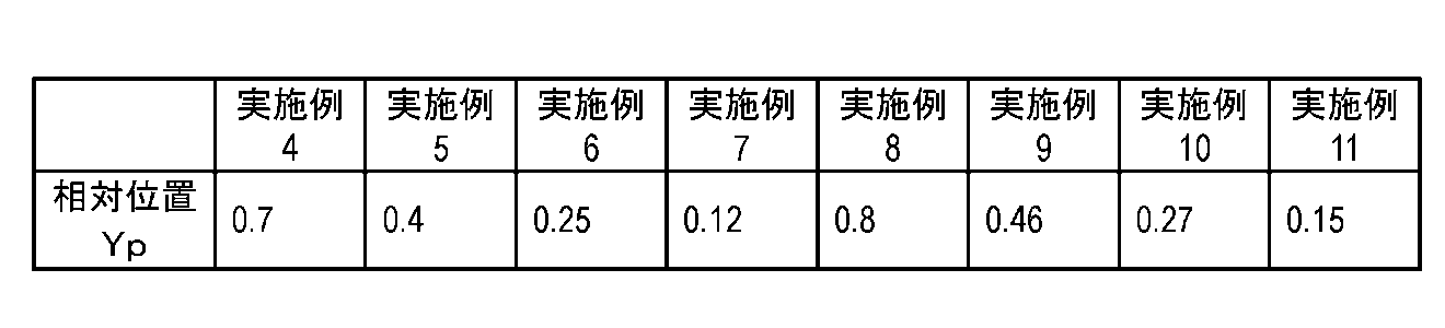
表3に、数値実施例12から数値実施例19の投写光学系100における相対位置Ypを示す。

[4-2.効果]
実施の形態4では、透過素子140の入射面の、基準縦交線BLと垂直な方向に対する曲率は、基準縦交線BLと平行な方向に対する曲率よりも大きい。これにより画像131の長辺方向全体から出射する主光線Lの、透過素子140への入射角を小さくできる。したがって、画像131の長辺方向全体から出射する主光線Lの透過素子140での反射を抑制でき、投影画像の長辺方向全体の輝度分布を均一化できる。
実施の形態4では、透過素子140の入射面の、基準縦交線BLと垂直な方向に対する曲率は、基準縦交線BLと平行な方向に対する曲率よりも大きい。これにより画像131の長辺方向全体から出射する主光線Lの、透過素子140への入射角を小さくできる。したがって、画像131の長辺方向全体から出射する主光線Lの透過素子140での反射を抑制でき、投影画像の長辺方向全体の輝度分布を均一化できる。
実施の形態4では、基準縦交線BLに入射する主光線Lは、基準交点BOにおける透過素子140の入射面の法線と平行になる光線を有する。これにより画像131の短辺方向全体から出射する主光線Lの、透過素子140への入射角を小さくできる。したがって、画像131の短辺方向全体から出射する主光線Lの、透過素子140への入射角を小さくできる。したがって、画像131の短辺方向全体から出射する主光線Lの透過素子140での反射を抑制でき、投影画像の短辺方向全体の輝度分布を均一化できる。
[4-3.変形例]
なお、実施の形態4では、透過素子140の入射面および反射面の両方をトロイダル面としたが、入射面及び反射面の少なくとも一方が、直交する二つの方向で互いに異なる曲率を有する面であればよい。また、透過素子140の入射面及び反射面の少なくとも一方を自由曲面としてもよい。
なお、実施の形態4では、透過素子140の入射面および反射面の両方をトロイダル面としたが、入射面及び反射面の少なくとも一方が、直交する二つの方向で互いに異なる曲率を有する面であればよい。また、透過素子140の入射面及び反射面の少なくとも一方を自由曲面としてもよい。
実施の形態4の反射光学系120は、第1ミラー121と第2ミラー122とを有するが、たとえば第1ミラー121を有していなくてもよい。すなわち、反射光学系120が、反射面が自由曲面の凹面である第2ミラー122のみで構成されてもよい。
実施の形態4では、反射面が平面の第1ミラー121を反射面が凹面の第2ミラー122よりも画像表示素子130に近い位置に配置しているが、この配置位置以外でもよい。すなわち、第2ミラー122を第1ミラー121よりも画像表示素子130に近い位置に配置してもよい。
実施の形態4の投写光学系100は、反射光学系120を有するが、反射光学系120を有していなくてもよい。
なお、実施の形態4の透過素子140の材料は、樹脂であるため、トロイダル面や自由曲面を加工しやすい。しかし、透過素子140の材料は、樹脂以外の材料でもよく、例えばガラスでもよい。
以下、上記各実施の形態に係る投写光学系を具体的に実施した数値実施例を説明する。なお、各数値実施例において、表中の長さの単位はすべて「mm」であり、画角の単位はすべて「°」である。また、各数値実施例において、「r」は曲率半径、「d」は面間隔、「nd」はd線に対する屈折率、「vd」はd線に対するアッベ数である。また、各数値実施例において、*印を付した面は非球面であり、非球面形状は次式で定義している。

ここで、
Z:光軸からの高さがhの非球面上の点から、非球面頂点の接平面までの距離、
h:光軸からの高さ、
r:頂点曲率半径、
κ:円錐定数、
An:n次の非球面係数
である。
Z:光軸からの高さがhの非球面上の点から、非球面頂点の接平面までの距離、
h:光軸からの高さ、
r:頂点曲率半径、
κ:円錐定数、
An:n次の非球面係数
である。
なお、非球面係数は、円錐常数K以外は0でない係数のみ記す。また、レンズ群データにおいて、レンズ構成長は、第1面から終面までの間隔、前側主点位置は、第1面からの距離、後側主点位置は、第1面からの距離である。
(数値実施例1)
以下のデータ1からデータ5に、数値実施例1の透過光学系の具体的なデータを示す。数値実施例1の透過光学系は、実施の形態1(図2)の透過光学系110に相当する。
以下のデータ1からデータ5に、数値実施例1の透過光学系の具体的なデータを示す。数値実施例1の透過光学系は、実施の形態1(図2)の透過光学系110に相当する。
データ1の面番号1の面は図2のプリズムPBの入射面、面番号2の面はプリズムPBの出射面を示す。面番号3の面は第1レンズL1の入射面、面番号4の面は第1レンズL1の出射面を示す。面番号5の面は第2レンズL2の入射面、面番号6の面は第2レンズL2及び第3レンズL3の接合面、面番号7の面は第3レンズL3及び第4レンズL4の接合面、面番号8の面は第4レンズL4の出射面を示す。面番号9の面は第5レンズL5の入射面、面番号10の面は第5レンズL5の出射面を示す。面番号11の面は開口絞りAを示す。面番号12の面は第6レンズL6の入射面、面番号13の面は第6レンズL6の出射面を示す。面番号14の面は第7レンズL7の入射面、面番号15の面は第7レンズL7の出射面を示す。面番号16の面は第8レンズL8の入射面、面番号17の面は第8レンズL8の出射面を示す。面番号18の面は第9レンズL9の入射面、面番号19の面は第9レンズL9及び第10レンズL10の接合面、面番号20の面は第10レンズL10の出射面を示す。面番号21の面は第11レンズL11の入射面、面番号22の面は第11レンズL11の出射面を示す。面番号23の面は第12レンズL12の入射面、面番号24の面は第12レンズL12の出射面を示す。面番号25の面は第13レンズL13の入射面、面番号26の面は第13レンズL13の出射面を示す。
データ2の面番号とデータ1の面番号は同じである。
データ4のレンズ1はプリズムPB、レンズ2~レンズ14は、それぞれ第1レンズL1~第13レンズL13に相当する。
データ5のレンズ群1は第1レンズL1、レンズ群2は第2レンズL2~第5レンズL5、レンズ群3は第6レンズL6~第10レンズL10、レンズ群4は第11レンズL11~第13レンズL13に相当する。
[データ1]
面データ
面番号 r d nd vd 有効径
画像表示素子 ∞
1 ∞ 14.99500 1.51680 64.2
2 ∞ 12.72300
3* 17.23400 8.00300 1.59349 67.0
4* 315.80500 可変 15.904
5 14.22900 1.50000 2.00069 25.5
6 8.67800 5.15000 1.49700 81.6
7 -34.20000 1.49900 1.90366 31.3
8 19.05500 0.49900
9 16.72300 6.17600 1.84666 23.8 4.690
10 -156.51000 可変
11(絞り) ∞ 14.49000 4.365
12 -120.75700 5.57200 1.78472 25.7
13 -56.17000 4.58500
14 -13.97000 1.00400 1.91082 35.2
15 -21.26300 0.29600
16 40.92700 7.46700 1.72342 38.0
17 -1962.27200 2.30200
18 -60.74800 1.19800 1.49700 81.6
19 39.71400 7.66800 1.63854 55.4
20 -168.43100 可変
21 25.80000 5.91200 1.78590 43.9
22 38.31000 9.60800
23* -53.54700 5.23500 1.68893 31.1 21.794
24* 24.57000 10.18400 24.740
25* -187.91700 11.83400 1.53775 74.7 21.205
26* -25.79200 21.794
[データ2]
非球面データ
第3面
K=-6.09400E-02, A4= 1.98117E-05, A6= 1.56997E-08, A8=-4.62804E-10
A10=-1.19399E-13, A12= 8.76682E-15, A14=-2.09485E-16, A16= 2.51704E-18
第4面
K=-1.00000E+02, A4= 4.71492E-05, A6= 1.33281E-07, A8=-5.51156E-10
A10=-1.55150E-11, A12=-2.25085E-14, A14= 2.52558E-15, A16=-7.77899E-18
第23面
K= 1.11067E+00, A4= 6.33930E-06, A6=-2.59108E-07, A8= 9.71178E-10
A10=-1.04904E-12, A12=-2.26872E-16, A14=-1.58698E-19, A16= 1.77042E-21
第24面
K=-1.66300E-02, A4=-4.34030E-05, A6= 3.86699E-08, A8=-1.80419E-11
A10=-1.24012E-13, A12= 1.25649E-16, A14= 1.87457E-19, A16=-5.10267E-22
第25面
K=-9.41608E+01, A4=-4.67773E-05, A6=-2.01376E-07, A8= 1.51882E-09
A10=-2.50674E-12, A12=-1.46260E-16, A14= 1.84046E-19, A16= 4.28649E-21
第26面
K=-2.08200E-02, A4=-1.69368E-05, A6=-5.91673E-08, A8= 1.07391E-10
A10= 1.23694E-13, A12=-2.06773E-16, A14=-2.43725E-20, A16= 8.16055E-22
[データ3]
各種データ
投写エリア 80” 100” 50”
焦点距離 37.3470 37.3021 37.4561
d4 5.6380 5.4328 6.2488
d10 4.3540 4.5571 3.7411
d20 2.6040 2.8223 1.5986
[データ4]
単レンズデータ
レンズ 始面 焦点距離
1 1 ∞
2 3 30.4108
3 5 -25.7030
4 6 14.5054
5 7 -13.3631
6 9 18.1415
7 12 128.9402
8 14 -47.8583
9 16 55.5055
10 18 -48.1287
11 19 51.0611
12 21 83.2253
13 23 -23.7961
14 25 54.2093
[データ5]
レンズ群データ
群 始面 焦点距離 レンズ構成長 前側主点位置 後側主点位置
1 1 30.41079 35.72100 22.32193 30.46131
2 5 75.30926 14.82400 0.46045 5.86471
3 11 219.36841 44.58200 31.27514 40.72933
4 21 717.01958 42.77300 138.60457 153.67075
(数値実施例2)
以下のデータ6からデータ9に、数値実施例2の透過光学系の具体的なデータを示す。数値実施例2の透過光学系は、実施の形態2(図3)に示す透過光学系110に相当する。
[データ1]
面データ
面番号 r d nd vd 有効径
画像表示素子 ∞
1 ∞ 14.99500 1.51680 64.2
2 ∞ 12.72300
3* 17.23400 8.00300 1.59349 67.0
4* 315.80500 可変 15.904
5 14.22900 1.50000 2.00069 25.5
6 8.67800 5.15000 1.49700 81.6
7 -34.20000 1.49900 1.90366 31.3
8 19.05500 0.49900
9 16.72300 6.17600 1.84666 23.8 4.690
10 -156.51000 可変
11(絞り) ∞ 14.49000 4.365
12 -120.75700 5.57200 1.78472 25.7
13 -56.17000 4.58500
14 -13.97000 1.00400 1.91082 35.2
15 -21.26300 0.29600
16 40.92700 7.46700 1.72342 38.0
17 -1962.27200 2.30200
18 -60.74800 1.19800 1.49700 81.6
19 39.71400 7.66800 1.63854 55.4
20 -168.43100 可変
21 25.80000 5.91200 1.78590 43.9
22 38.31000 9.60800
23* -53.54700 5.23500 1.68893 31.1 21.794
24* 24.57000 10.18400 24.740
25* -187.91700 11.83400 1.53775 74.7 21.205
26* -25.79200 21.794
[データ2]
非球面データ
第3面
K=-6.09400E-02, A4= 1.98117E-05, A6= 1.56997E-08, A8=-4.62804E-10
A10=-1.19399E-13, A12= 8.76682E-15, A14=-2.09485E-16, A16= 2.51704E-18
第4面
K=-1.00000E+02, A4= 4.71492E-05, A6= 1.33281E-07, A8=-5.51156E-10
A10=-1.55150E-11, A12=-2.25085E-14, A14= 2.52558E-15, A16=-7.77899E-18
第23面
K= 1.11067E+00, A4= 6.33930E-06, A6=-2.59108E-07, A8= 9.71178E-10
A10=-1.04904E-12, A12=-2.26872E-16, A14=-1.58698E-19, A16= 1.77042E-21
第24面
K=-1.66300E-02, A4=-4.34030E-05, A6= 3.86699E-08, A8=-1.80419E-11
A10=-1.24012E-13, A12= 1.25649E-16, A14= 1.87457E-19, A16=-5.10267E-22
第25面
K=-9.41608E+01, A4=-4.67773E-05, A6=-2.01376E-07, A8= 1.51882E-09
A10=-2.50674E-12, A12=-1.46260E-16, A14= 1.84046E-19, A16= 4.28649E-21
第26面
K=-2.08200E-02, A4=-1.69368E-05, A6=-5.91673E-08, A8= 1.07391E-10
A10= 1.23694E-13, A12=-2.06773E-16, A14=-2.43725E-20, A16= 8.16055E-22
[データ3]
各種データ
投写エリア 80” 100” 50”
焦点距離 37.3470 37.3021 37.4561
d4 5.6380 5.4328 6.2488
d10 4.3540 4.5571 3.7411
d20 2.6040 2.8223 1.5986
[データ4]
単レンズデータ
レンズ 始面 焦点距離
1 1 ∞
2 3 30.4108
3 5 -25.7030
4 6 14.5054
5 7 -13.3631
6 9 18.1415
7 12 128.9402
8 14 -47.8583
9 16 55.5055
10 18 -48.1287
11 19 51.0611
12 21 83.2253
13 23 -23.7961
14 25 54.2093
[データ5]
レンズ群データ
群 始面 焦点距離 レンズ構成長 前側主点位置 後側主点位置
1 1 30.41079 35.72100 22.32193 30.46131
2 5 75.30926 14.82400 0.46045 5.86471
3 11 219.36841 44.58200 31.27514 40.72933
4 21 717.01958 42.77300 138.60457 153.67075
(数値実施例2)
以下のデータ6からデータ9に、数値実施例2の透過光学系の具体的なデータを示す。数値実施例2の透過光学系は、実施の形態2(図3)に示す透過光学系110に相当する。
データ6の面番号は、データ1の面番号と同じ面を示す。
データ7の面番号とデータ6の面番号は同じである。
データ9のレンズ番号は、データ4のレンズ番号と同じレンズを示す。
[データ6]
面データ
面番号 r d nd vd 有効径
画像表示素子 ∞
1 ∞ 15.00000 1.51680 64.2
2 ∞ 12.66300
3* 17.19300 8.00000 1.59349 67.0
4* 290.32200 5.10600 12.510
5 14.48000 1.50000 2.00069 25.5
6 8.78200 5.08500 1.49700 81.6
7 -32.37200 1.50000 1.90366 31.3
8 19.67100 0.50000
9 17.21600 3.54300 1.84666 23.8 4.696
10 -122.74800 6.15600
11(絞り) ∞ 14.49800 4.330
12 -93.48000 4.07700 1.78472 25.7
13 -52.70900 4.39600
14 -13.56800 1.00000 1.91082 35.2
15 -19.77000 0.50000
16 40.73100 10.43500 1.72342 38.0
17 973.57600 1.96300
18 -77.44100 1.20000 1.49700 81.6
19 36.71000 11.51300 1.63854 55.4
20 -342.73900 2.60000
21 25.66400 6.04000 1.78590 43.9
22 37.83000 9.89400
23* -55.70200 3.94100 1.68893 31.1 21.756
24* 24.47000 10.21300 24.476
25* -210.37000 11.57500 1.53775 74.7 20.668
26* -25.63500 21.756
[データ7]
非球面データ
第3面
K=-6.04699E-02, A4= 1.98616E-05, A6= 7.35058E-09, A8=-5.05794E-10
A10= 8.61968E-13, A12= 1.71901E-14, A14=-2.36028E-16, A16= 2.18449E-18
第4面
K=-1.00000E+02, A4= 4.69902E-05, A6= 1.18022E-07, A8=-5.22552E-10
A10=-1.47332E-11, A12= 2.91990E-15, A14= 2.91462E-15, A16=-1.40152E-17
第23面
K= 9.17327E-01, A4= 6.73643E-06, A6=-2.61030E-07, A8= 9.70513E-10
A10=-1.04173E-12, A12=-2.23528E-16, A14=-2.05136E-19, A16= 1.76480E-21
第24面
K=-8.76498E-03, A4=-4.37627E-05, A6= 4.02825E-08, A8=-1.52276E-11
A10=-1.22414E-13, A12= 1.22226E-16, A14= 1.72616E-19, A16=-5.04200E-22
第25面
K=-1.00000E+02, A4=-4.72581E-05, A6=-2.01657E-07, A8= 1.52205E-09
A10=-2.49780E-12, A12=-1.19138E-16, A14= 2.16018E-19, A16= 4.21484E-21
第26面
K=-1.08792E-02, A4=-1.70130E-05, A6=-6.04647E-08, A8= 1.04246E-10
A10= 1.35513E-13, A12=-1.79293E-16, A14=-1.16542E-21, A16= 8.03042E-22
[データ8]
各種データ
焦点距離 38.1700
[データ9]
単レンズデータ
レンズ 始面 焦点距離
1 1 ∞
2 3 30.4604
3 5 -25.6835
4 6 14.4940
5 7 -13.3576
6 9 18.0422
7 12 147.5199
8 14 -51.4384
9 16 58.4874
10 18 -49.9354
11 19 52.5497
12 21 83.3357
13 23 -24.1927
14 25 53.1220
(数値実施例3)
以下のデータ10からデータ14に、数値実施例3の透過光学系の具体的なデータを示す。数値実施例3の透過光学系は、実施の形態3(図4)の透過光学系110に相当する。
[データ6]
面データ
面番号 r d nd vd 有効径
画像表示素子 ∞
1 ∞ 15.00000 1.51680 64.2
2 ∞ 12.66300
3* 17.19300 8.00000 1.59349 67.0
4* 290.32200 5.10600 12.510
5 14.48000 1.50000 2.00069 25.5
6 8.78200 5.08500 1.49700 81.6
7 -32.37200 1.50000 1.90366 31.3
8 19.67100 0.50000
9 17.21600 3.54300 1.84666 23.8 4.696
10 -122.74800 6.15600
11(絞り) ∞ 14.49800 4.330
12 -93.48000 4.07700 1.78472 25.7
13 -52.70900 4.39600
14 -13.56800 1.00000 1.91082 35.2
15 -19.77000 0.50000
16 40.73100 10.43500 1.72342 38.0
17 973.57600 1.96300
18 -77.44100 1.20000 1.49700 81.6
19 36.71000 11.51300 1.63854 55.4
20 -342.73900 2.60000
21 25.66400 6.04000 1.78590 43.9
22 37.83000 9.89400
23* -55.70200 3.94100 1.68893 31.1 21.756
24* 24.47000 10.21300 24.476
25* -210.37000 11.57500 1.53775 74.7 20.668
26* -25.63500 21.756
[データ7]
非球面データ
第3面
K=-6.04699E-02, A4= 1.98616E-05, A6= 7.35058E-09, A8=-5.05794E-10
A10= 8.61968E-13, A12= 1.71901E-14, A14=-2.36028E-16, A16= 2.18449E-18
第4面
K=-1.00000E+02, A4= 4.69902E-05, A6= 1.18022E-07, A8=-5.22552E-10
A10=-1.47332E-11, A12= 2.91990E-15, A14= 2.91462E-15, A16=-1.40152E-17
第23面
K= 9.17327E-01, A4= 6.73643E-06, A6=-2.61030E-07, A8= 9.70513E-10
A10=-1.04173E-12, A12=-2.23528E-16, A14=-2.05136E-19, A16= 1.76480E-21
第24面
K=-8.76498E-03, A4=-4.37627E-05, A6= 4.02825E-08, A8=-1.52276E-11
A10=-1.22414E-13, A12= 1.22226E-16, A14= 1.72616E-19, A16=-5.04200E-22
第25面
K=-1.00000E+02, A4=-4.72581E-05, A6=-2.01657E-07, A8= 1.52205E-09
A10=-2.49780E-12, A12=-1.19138E-16, A14= 2.16018E-19, A16= 4.21484E-21
第26面
K=-1.08792E-02, A4=-1.70130E-05, A6=-6.04647E-08, A8= 1.04246E-10
A10= 1.35513E-13, A12=-1.79293E-16, A14=-1.16542E-21, A16= 8.03042E-22
[データ8]
各種データ
焦点距離 38.1700
[データ9]
単レンズデータ
レンズ 始面 焦点距離
1 1 ∞
2 3 30.4604
3 5 -25.6835
4 6 14.4940
5 7 -13.3576
6 9 18.0422
7 12 147.5199
8 14 -51.4384
9 16 58.4874
10 18 -49.9354
11 19 52.5497
12 21 83.3357
13 23 -24.1927
14 25 53.1220
(数値実施例3)
以下のデータ10からデータ14に、数値実施例3の透過光学系の具体的なデータを示す。数値実施例3の透過光学系は、実施の形態3(図4)の透過光学系110に相当する。
データ10の面番号1~面番号15は、データ1の面番号1~面番号15と同じ面を示す。データ10の面番号16は第18レンズL18の入射面、面番号17は第18レンズL18及び第9レンズL9の接合面、面番号18は第9レンズL9の出射面を示す。面番号19は第11レンズL11の入射面、面番号20は第11レンズL11の出射面を示す。面番号21は第12レンズL12の入射面、面番号22は第12レンズL12の出射面を示す。面番号23は第13レンズL13の入射面、面番号24は第13レンズL13の出射面を示す。
データ11の面番号とデータ10の面番号は同じである。
データ13のレンズ1はプリズムPB、レンズ2~レンズ8は、第1レンズL1~第7レンズL7に相当する。レンズ9は第18レンズL18に相当する。レンズ10は第9レンズL9に相当する。レンズ11~レンズ13は第11レンズL11~第13レンズL13に相当する。
データ14のレンズ群1は第1レンズL1、レンズ群2は第2レンズL2~第5レンズL5、レンズ群3は第6レンズL6、第7レンズL7、第18レンズL18、及び第9レンズL9に相当する。レンズ群4は第11レンズL11~第13レンズL13に相当する。
[データ10]
面データ
面番号 r d nd vd 有効径
画像表示素子 ∞
1 ∞ 15.00000 1.51680 64.2
2 ∞ 12.46900
3* 16.60900 8.00000 1.59349 67.0
4* 238.82100 可変 15.490
5 15.08000 1.50000 2.00069 25.5
6 8.82500 5.31000 1.49700 81.6
7 -29.89700 1.50000 1.90366 31.3
8 18.82700 0.50000
9 17.07700 7.44700 1.92119 24.0 4.680
10 -120.94700 可変
11(絞り) ∞ 14.62800 4.382
12 -303.76700 8.37600 1.75211 25.0
13 -46.44600 2.92800
14 -15.10700 1.00000 1.91082 35.2
15 -27.46200 4.63100
16 37.26600 11.91600 1.63854 55.4
17 -37.26600 1.20000 1.49700 81.6
18 90.86800 可変
19 24.13000 6.09300 1.74400 44.8
20 32.14500 9.13600
21* -65.96100 5.10000 1.68893 31.1 21.227
22* 24.63500 9.98500 20.654
23* -271.41000 11.80000 1.52500 70.3 21.801
24* -26.13800 21.801
[データ11]
非球面データ
第3面
K=-2.64764E-02, A4= 1.95203E-05, A6= 2.77906E-08, A8=-5.48222E-10
A10= 1.45564E-12, A12= 2.44601E-14, A14=-2.53264E-16, A16= 2.83945E-18
第4面
K=-1.00000E+02, A4= 5.09253E-05, A6= 1.64368E-07, A8=-2.22116E-10
A10=-1.70214E-11, A12=-6.77176E-15, A14= 3.59876E-15, A16=-1.22797E-17
第21面
K= 4.24168E-01, A4= 7.35890E-06, A6=-2.63924E-07, A8= 9.63867E-10
A10=-1.04909E-12, A12=-2.43452E-16, A14=-2.45190E-19, A16= 2.11315E-21
第22面
K= 9.83767E-03, A4=-4.47000E-05, A6= 4.34712E-08, A8=-8.91954E-12
A10=-1.22273E-13, A12= 9.34976E-17, A14= 8.60890E-20, A16=-5.31655E-22
第23面
K=-1.11269E+02, A4=-5.01495E-05, A6=-2.02921E-07, A8= 1.52178E-09
A10=-2.49636E-12, A12=-1.24985E-16, A14= 1.70196E-19, A16= 3.87907E-21
第24面
K=-1.91793E-03, A4=-1.75117E-05, A6=-6.08590E-08, A8= 1.03604E-10
A10= 1.48543E-13, A12=-1.59856E-16, A14=-3.66014E-20, A16= 6.50430E-22
[データ12]
各種データ
投写エリア 80” 100” 50”
焦点距離 37.9403 37.8961 38.0889
d4 4.8310 4.6458 5.4573
d10 4.3410 4.5260 3.7171
d18 3.8260 4.0665 2.9391
[データ13]
単レンズデータ
レンズ 始面 焦点距離
1 1 ∞
2 3 29.6789
3 5 -24.1589
4 6 14.3637
5 7 -12.5997
6 9 16.6758
7 12 71.8962
8 14 -38.3461
9 16 31.1194
10 17 -53.0099
11 19 98.2208
12 21 -25.4504
13 23 54.1942
[データ14]
レンズ群データ
群 始面 焦点距離 レンズ構成長 前側主点位置 後側主点位置
1 1 29.67893 35.46900 21.98797 30.14473
2 5 75.48370 16.25700 3.10935 9.06057
3 11 213.83645 44.67900 33.85084 43.49828
4 19 834.01525 42.11400 161.64749 183.52380
以下の数値実施例4~数値実施例11の透過光学系110は、実施の形態4(図5)の透過光学系110に相当する。数値実施例12~数値実施例19の透過光学系110は、実施の形態4の変形例の透過光学系110に相当する。数値実施例4~数値実施例19では、反射光学系120とスクリーン1との間に透過素子140を配置した。
[データ10]
面データ
面番号 r d nd vd 有効径
画像表示素子 ∞
1 ∞ 15.00000 1.51680 64.2
2 ∞ 12.46900
3* 16.60900 8.00000 1.59349 67.0
4* 238.82100 可変 15.490
5 15.08000 1.50000 2.00069 25.5
6 8.82500 5.31000 1.49700 81.6
7 -29.89700 1.50000 1.90366 31.3
8 18.82700 0.50000
9 17.07700 7.44700 1.92119 24.0 4.680
10 -120.94700 可変
11(絞り) ∞ 14.62800 4.382
12 -303.76700 8.37600 1.75211 25.0
13 -46.44600 2.92800
14 -15.10700 1.00000 1.91082 35.2
15 -27.46200 4.63100
16 37.26600 11.91600 1.63854 55.4
17 -37.26600 1.20000 1.49700 81.6
18 90.86800 可変
19 24.13000 6.09300 1.74400 44.8
20 32.14500 9.13600
21* -65.96100 5.10000 1.68893 31.1 21.227
22* 24.63500 9.98500 20.654
23* -271.41000 11.80000 1.52500 70.3 21.801
24* -26.13800 21.801
[データ11]
非球面データ
第3面
K=-2.64764E-02, A4= 1.95203E-05, A6= 2.77906E-08, A8=-5.48222E-10
A10= 1.45564E-12, A12= 2.44601E-14, A14=-2.53264E-16, A16= 2.83945E-18
第4面
K=-1.00000E+02, A4= 5.09253E-05, A6= 1.64368E-07, A8=-2.22116E-10
A10=-1.70214E-11, A12=-6.77176E-15, A14= 3.59876E-15, A16=-1.22797E-17
第21面
K= 4.24168E-01, A4= 7.35890E-06, A6=-2.63924E-07, A8= 9.63867E-10
A10=-1.04909E-12, A12=-2.43452E-16, A14=-2.45190E-19, A16= 2.11315E-21
第22面
K= 9.83767E-03, A4=-4.47000E-05, A6= 4.34712E-08, A8=-8.91954E-12
A10=-1.22273E-13, A12= 9.34976E-17, A14= 8.60890E-20, A16=-5.31655E-22
第23面
K=-1.11269E+02, A4=-5.01495E-05, A6=-2.02921E-07, A8= 1.52178E-09
A10=-2.49636E-12, A12=-1.24985E-16, A14= 1.70196E-19, A16= 3.87907E-21
第24面
K=-1.91793E-03, A4=-1.75117E-05, A6=-6.08590E-08, A8= 1.03604E-10
A10= 1.48543E-13, A12=-1.59856E-16, A14=-3.66014E-20, A16= 6.50430E-22
[データ12]
各種データ
投写エリア 80” 100” 50”
焦点距離 37.9403 37.8961 38.0889
d4 4.8310 4.6458 5.4573
d10 4.3410 4.5260 3.7171
d18 3.8260 4.0665 2.9391
[データ13]
単レンズデータ
レンズ 始面 焦点距離
1 1 ∞
2 3 29.6789
3 5 -24.1589
4 6 14.3637
5 7 -12.5997
6 9 16.6758
7 12 71.8962
8 14 -38.3461
9 16 31.1194
10 17 -53.0099
11 19 98.2208
12 21 -25.4504
13 23 54.1942
[データ14]
レンズ群データ
群 始面 焦点距離 レンズ構成長 前側主点位置 後側主点位置
1 1 29.67893 35.46900 21.98797 30.14473
2 5 75.48370 16.25700 3.10935 9.06057
3 11 213.83645 44.67900 33.85084 43.49828
4 19 834.01525 42.11400 161.64749 183.52380
以下の数値実施例4~数値実施例11の透過光学系110は、実施の形態4(図5)の透過光学系110に相当する。数値実施例12~数値実施例19の透過光学系110は、実施の形態4の変形例の透過光学系110に相当する。数値実施例4~数値実施例19では、反射光学系120とスクリーン1との間に透過素子140を配置した。
数値実施例4、5、6および7における透過光学系110のレンズテータは数値実施例1と同様であるため説明を省略する。下記のデータ15に、数値実施例4、5、6および7の透過素子140のレンズデータを示す。
データ15の面番号1は、透過素子140の入射面を示す。面番号2は、透過素子140の出射面を示す。
[データ15]
面データ
面番号 X曲率半径 Y曲率半径 d Nd Vd
1 -198 ∞ 2.0 1.5168 64.2
2 -200 ∞
(数値実施例4)
数値実施例4では、透過素子140を、画像表示素子130の表示面に直交する方向に対して70度の角度で傾けて配置した。
[データ15]
面データ
面番号 X曲率半径 Y曲率半径 d Nd Vd
1 -198 ∞ 2.0 1.5168 64.2
2 -200 ∞
(数値実施例4)
数値実施例4では、透過素子140を、画像表示素子130の表示面に直交する方向に対して70度の角度で傾けて配置した。
その結果を図7に示す。図7のグラフの縦軸は、透過素子140の基準縦交線BLに入射する主光線Lの角度(入射角)を示す。図7のグラフの横軸は、基準縦交線BLに入射する主光線Lのスクリーン1上における相対位置(Yp)を示す。相対位置が0の位置とは、スクリーン1に投写される投影画像の内、投写光学系100の最終出射面から一番近い位置に入射する主光線Lの位置を示す。相対位置が1である位置とは、スクリーン1に投写される投影画像の内、投写光学系100の最終出射面から最も離れた位置に入射する光線の位置を示す。言い換えると、画像表示素子130から出射する光線の内、図5のY軸方向の最も下から出射する光線が到達するスクリーン1上の位置が0、最も上から出射する光線が到達するスクリーン1上の位置が1となる。
図7に示すように、数値実施例4では、スクリーン1上の相対位置0.7に到達する主光線Lは、透過素子140の基準縦交線BLに入射する角度が0となっている。また、基準縦交線BLに入射する主光線Lの入射角の内、最も大きい角度は50度であることが分かる。
(数値実施例5)
数値実施例5では、透過素子140を、画像表示素子130の面に直交する方向に対して60度の角度で傾けて配置した。その結果、図8に示す様に、数値実施例5では、スクリーン1上の相対位置0.4に到達する主光線Lは、透過素子140の基準縦交線BLに入射する角度が0となっている。また、基準縦交線BLに入射する主光線Lの入射角の内、最も大きい角度は40度であることが分かる。
数値実施例5では、透過素子140を、画像表示素子130の面に直交する方向に対して60度の角度で傾けて配置した。その結果、図8に示す様に、数値実施例5では、スクリーン1上の相対位置0.4に到達する主光線Lは、透過素子140の基準縦交線BLに入射する角度が0となっている。また、基準縦交線BLに入射する主光線Lの入射角の内、最も大きい角度は40度であることが分かる。
(数値実施例6)
数値実施例6では、透過素子140を、画像表示素子130の面に直交する方向に対して50度の角度で傾けて配置した。その結果、図9に示す様に、数値実施例6では、スクリーン1上の相対位置0.25に到達する主光線Lは、透過素子140の基準縦交線BLに入射する角度が0となっている。また、基準縦交線BLに入射する主光線Lの入射角の内、最も大きい角度は、30度であることが分かる。
数値実施例6では、透過素子140を、画像表示素子130の面に直交する方向に対して50度の角度で傾けて配置した。その結果、図9に示す様に、数値実施例6では、スクリーン1上の相対位置0.25に到達する主光線Lは、透過素子140の基準縦交線BLに入射する角度が0となっている。また、基準縦交線BLに入射する主光線Lの入射角の内、最も大きい角度は、30度であることが分かる。
(数値実施例7)
数値実施例7では、透過素子140を、画像表示素子130の面に直交する方向に対して40度の角度で傾けて配置した。その結果、図10に示す様に、数値実施例7では、スクリーン1上の相対位置0.12に到達する主光線Lは、透過素子140の基準縦交線BL位置に入射する角度が0となっている。また、基準縦交線BLに入射する主光線Lの入射角の内、最も大きい角度は35度であることが分かる。
数値実施例7では、透過素子140を、画像表示素子130の面に直交する方向に対して40度の角度で傾けて配置した。その結果、図10に示す様に、数値実施例7では、スクリーン1上の相対位置0.12に到達する主光線Lは、透過素子140の基準縦交線BL位置に入射する角度が0となっている。また、基準縦交線BLに入射する主光線Lの入射角の内、最も大きい角度は35度であることが分かる。
数値実施例8、9、10および11における透過光学系110のレンズテータは数値実施例1と同様であるため説明を省略する。下記データ16に、数値実施例8、9、10および11の透過素子140のレンズデータを示す。
データ16の面番号1は、透過素子140の入射面を示す。面番号2は、透過素子140の出射面を示す。
[データ16]
面データ
面番号 X曲率半径 Y曲率半径 d Nd Vd
1 -248 -298 2.0 1.5168 64.2
2 -250 -300
(数値実施例8)
数値実施例8では、透過素子140を、画像表示素子130の面に直交する方向に対して70度の角度で傾けて配置した。その結果、図11に示す様に、数値実施例8では、スクリーン1上の相対位置0.8に到達する主光線Lは、透過素子140の基準縦交線BLに入射する角度が0となっている。また、基準縦交線BLに入射する主光線Lの入射角の内、最も大きい角度は、47度であることが分かる。
[データ16]
面データ
面番号 X曲率半径 Y曲率半径 d Nd Vd
1 -248 -298 2.0 1.5168 64.2
2 -250 -300
(数値実施例8)
数値実施例8では、透過素子140を、画像表示素子130の面に直交する方向に対して70度の角度で傾けて配置した。その結果、図11に示す様に、数値実施例8では、スクリーン1上の相対位置0.8に到達する主光線Lは、透過素子140の基準縦交線BLに入射する角度が0となっている。また、基準縦交線BLに入射する主光線Lの入射角の内、最も大きい角度は、47度であることが分かる。
(数値実施例9)
数値実施例9では、透過素子140を、画像表示素子130の面に直交する方向に対して60度の角度で傾けて配置した。その結果、図12に示す様に、数値実施例9では、スクリーン1上の相対位置0.46に到達する主光線Lは、透過素子140の基準縦交線BLに入射する角度が0となっている。また、基準縦交線BLに入射する主光線Lの入射角の内、最も大きい角度は、38度であることが分かる。
数値実施例9では、透過素子140を、画像表示素子130の面に直交する方向に対して60度の角度で傾けて配置した。その結果、図12に示す様に、数値実施例9では、スクリーン1上の相対位置0.46に到達する主光線Lは、透過素子140の基準縦交線BLに入射する角度が0となっている。また、基準縦交線BLに入射する主光線Lの入射角の内、最も大きい角度は、38度であることが分かる。
(数値実施例10)
数値実施例10では、透過素子140を、画像表示素子130の面に直交する方向に対して50度の角度で傾けて配置した。その結果、図13に示す様に、数値実施例10では、スクリーン1上の相対位置0.27に到達する主光線Lは、透過素子140の基準縦交線BLに入射する角度が0となっている。また、基準縦交線BLに入射する主光線Lの入射角の内、最も大きい角度は、27度であることが分かる。
数値実施例10では、透過素子140を、画像表示素子130の面に直交する方向に対して50度の角度で傾けて配置した。その結果、図13に示す様に、数値実施例10では、スクリーン1上の相対位置0.27に到達する主光線Lは、透過素子140の基準縦交線BLに入射する角度が0となっている。また、基準縦交線BLに入射する主光線Lの入射角の内、最も大きい角度は、27度であることが分かる。
(数値実施例11)
数値実施例11では、透過素子140を、画像表示素子130の面に直交する方向に対して40度の角度で傾けて配置した。その結果、図14に示す様に、数値実施例11では、スクリーン1上の相対位置0.15に到達する主光線Lは、透過素子140の基準縦交線BLに入射する角度が0となっている。また、基準縦交線BLに入射する主光線Lの入射角の内、最も大きい角度は、34度であることが分かる。
数値実施例11では、透過素子140を、画像表示素子130の面に直交する方向に対して40度の角度で傾けて配置した。その結果、図14に示す様に、数値実施例11では、スクリーン1上の相対位置0.15に到達する主光線Lは、透過素子140の基準縦交線BLに入射する角度が0となっている。また、基準縦交線BLに入射する主光線Lの入射角の内、最も大きい角度は、34度であることが分かる。
次に、数値実施例12、13、14および15について説明する。数値実施例12~15は、実施の形態4の変形例に相当する。数値実施例12~15における透過光学系110のレンズテータは数値実施例1と同様であるため説明を省略する。下記データ17に、数値実施例12~15の透過素子140のレンズデータを示す。
データ17の面番号1は、透過素子140の入射面を示す。面番号2は、透過素子140の出射面を示す。
[データ17]
面データ
面番号 X曲率半径 Y曲率半径 d Nd Vd
1 -113 ∞ 2.0 1.5168 64.2
2 -115 ∞
以下の数値実施例12~15では、第1ミラー121と第2ミラー122の配置位置を逆にした。つまり、反射面が自由曲面である第2ミラー122を、反射面が平面である第1ミラー121よりも画像表示素子130に近い位置に配置した。
[データ17]
面データ
面番号 X曲率半径 Y曲率半径 d Nd Vd
1 -113 ∞ 2.0 1.5168 64.2
2 -115 ∞
以下の数値実施例12~15では、第1ミラー121と第2ミラー122の配置位置を逆にした。つまり、反射面が自由曲面である第2ミラー122を、反射面が平面である第1ミラー121よりも画像表示素子130に近い位置に配置した。
(数値実施例12)
数値実施例12では、透過素子140を、画像表示素子130の面に直交する方向に対して70度の角度で傾けて配置した。その結果、図15に示す様に、数値実施例12では、スクリーン1上の相対位置0.08に到達する主光線Lは、透過素子140の基準縦交線BLに入射する角度が0となっている。また、基準縦交線BLに入射する主光線Lの入射角の内、最も大きい角度は、32度であることが分かる。
数値実施例12では、透過素子140を、画像表示素子130の面に直交する方向に対して70度の角度で傾けて配置した。その結果、図15に示す様に、数値実施例12では、スクリーン1上の相対位置0.08に到達する主光線Lは、透過素子140の基準縦交線BLに入射する角度が0となっている。また、基準縦交線BLに入射する主光線Lの入射角の内、最も大きい角度は、32度であることが分かる。
(数値実施例13)
数値実施例13では、透過素子140を、画像表示素子130の面に直交する方向に対して60度の角度で傾けて配置した。その結果、図16に示す様に、数値実施例13では、スクリーン1上の相対位置0.2に到達する主光線Lは、透過素子140の基準縦交線BLに入射する角度が0となっている。また、基準縦交線BLに入射する主光線Lの入射角の内、最も大きい角度は、21度であることが分かる。
数値実施例13では、透過素子140を、画像表示素子130の面に直交する方向に対して60度の角度で傾けて配置した。その結果、図16に示す様に、数値実施例13では、スクリーン1上の相対位置0.2に到達する主光線Lは、透過素子140の基準縦交線BLに入射する角度が0となっている。また、基準縦交線BLに入射する主光線Lの入射角の内、最も大きい角度は、21度であることが分かる。
(数値実施例14)
数値実施例14では、透過素子140を、画像表示素子130の面に直交する方向に対して50度の角度で傾けて配置した。その結果、図17に示す様に、数値実施例14では、スクリーン1上の相対位置0.46に到達する主光線Lは、透過素子140の基準縦交線BLに入射する角度が0となっている。また、基準縦交線BLに入射する主光線Lの入射角の内、最も大きい角度は、31度であることが分かる。
数値実施例14では、透過素子140を、画像表示素子130の面に直交する方向に対して50度の角度で傾けて配置した。その結果、図17に示す様に、数値実施例14では、スクリーン1上の相対位置0.46に到達する主光線Lは、透過素子140の基準縦交線BLに入射する角度が0となっている。また、基準縦交線BLに入射する主光線Lの入射角の内、最も大きい角度は、31度であることが分かる。
(数値実施例15)
数値実施例15では、透過素子140を、画像表示素子130の面に直交する方向に対して40度の角度で傾けて配置した。その結果、図18に示す様に、数値実施例15では、スクリーン1上の相対位置0.92に到達する主光線Lは、透過素子140の基準縦交線BLに入射する角度が0となっている。また、基準縦交線BLに入射する主光線Lの入射角の内、最も大きい角度は、41度であることが分かる。
数値実施例15では、透過素子140を、画像表示素子130の面に直交する方向に対して40度の角度で傾けて配置した。その結果、図18に示す様に、数値実施例15では、スクリーン1上の相対位置0.92に到達する主光線Lは、透過素子140の基準縦交線BLに入射する角度が0となっている。また、基準縦交線BLに入射する主光線Lの入射角の内、最も大きい角度は、41度であることが分かる。
次に、数値実施例16、17、18および19について説明する。数値実施例16~19は、実施の形態4の変形例に相当する。数値実施例16~19における透過光学系110のレンズテータは数値実施例1と同様であるため説明を省略する。下記データ18に、数値実施例16~19の透過素子140のレンズデータを示す。
データ18の面番号1は、透過素子140の入射面を示す。面番号2は、透過素子140の出射面を示す。
[データ18]
面データ
面番号 X曲率半径 Y曲率半径 d Nd Vd
1 -113 ∞ 2.0 1.5168 64.2
2 -115 ∞
以下の数値実施例16、17、18および19では、平面ミラーである第1ミラー121を用いず、第2ミラー122のみを用いた。
[データ18]
面データ
面番号 X曲率半径 Y曲率半径 d Nd Vd
1 -113 ∞ 2.0 1.5168 64.2
2 -115 ∞
以下の数値実施例16、17、18および19では、平面ミラーである第1ミラー121を用いず、第2ミラー122のみを用いた。
(数値実施例16)
数値実施例16では、透過素子140を、画像表示素子130の面に直交する方向に対して70度の角度で傾けて配置した。その結果、図19に示す様に、数値実施例16では、スクリーン1上の相対位置0.04に到達する主光線Lは、透過素子140の基準縦交線BLに入射する角度が0となっている。また、基準縦交線BLに入射する主光線Lの入射角の内、最も大きい角度は、36度であることが分かる。
数値実施例16では、透過素子140を、画像表示素子130の面に直交する方向に対して70度の角度で傾けて配置した。その結果、図19に示す様に、数値実施例16では、スクリーン1上の相対位置0.04に到達する主光線Lは、透過素子140の基準縦交線BLに入射する角度が0となっている。また、基準縦交線BLに入射する主光線Lの入射角の内、最も大きい角度は、36度であることが分かる。
(数値実施例17)
数値実施例17では、透過素子140を、画像表示素子130の面に直交する方向に対して60度の角度で傾けて配置した。その結果、図20に示す様に、数値実施例17では、スクリーン1上の相対位置0.16に到達する主光線Lは、透過素子140の基準縦交線BLに入射する角度が0となっている。また、基準縦交線BLに入射する主光線Lの入射角の内、最も大きい角度は、26度であることが分かる。
数値実施例17では、透過素子140を、画像表示素子130の面に直交する方向に対して60度の角度で傾けて配置した。その結果、図20に示す様に、数値実施例17では、スクリーン1上の相対位置0.16に到達する主光線Lは、透過素子140の基準縦交線BLに入射する角度が0となっている。また、基準縦交線BLに入射する主光線Lの入射角の内、最も大きい角度は、26度であることが分かる。
(数値実施例18)
数値実施例18では、透過素子140を、画像表示素子130の面に直交する方向に対して50度の角度で傾けて配置した。その結果、図21に示す様に、数値実施例18では、スクリーン1上の相対位置0.32に到達する主光線Lは、透過素子140の基準縦交線BLに入射する角度が0となっている。また、基準縦交線BLに入射する主光線Lの入射角の内、最も大きい角度は、26度であることが分かる。
数値実施例18では、透過素子140を、画像表示素子130の面に直交する方向に対して50度の角度で傾けて配置した。その結果、図21に示す様に、数値実施例18では、スクリーン1上の相対位置0.32に到達する主光線Lは、透過素子140の基準縦交線BLに入射する角度が0となっている。また、基準縦交線BLに入射する主光線Lの入射角の内、最も大きい角度は、26度であることが分かる。
(数値実施例19)
数値実施例19では、透過素子140を、画像表示素子130の面に直交する方向に対して40度の角度で傾けて配置した。その結果、図22に示す様に、数値実施例19では、スクリーン1上の相対位置0.62に到達する主光線Lは、透過素子140の基準縦交線BLに入射する角度が0となっている。また、基準縦交線BLに入射する主光線Lの入射角の内、最も大きい角度は、36度であることが分かる。
数値実施例19では、透過素子140を、画像表示素子130の面に直交する方向に対して40度の角度で傾けて配置した。その結果、図22に示す様に、数値実施例19では、スクリーン1上の相対位置0.62に到達する主光線Lは、透過素子140の基準縦交線BLに入射する角度が0となっている。また、基準縦交線BLに入射する主光線Lの入射角の内、最も大きい角度は、36度であることが分かる。
(比較例1)
数値実施例4、5、6及び7と比較するために、比較例1では、透過素子140を、画像表示素子130の面に直交する方向に対して90度の角度で傾けて配置した。比較例1の投写光学系100のその他の構成は、数値実施例4、5、6及び7と同様の構成である。その結果、図23に示す様に、比較例1では、スクリーン1上に到達する主光線Lは、透過素子140の基準縦光線BLに入射する角度が0とならない。そのため、基準縦交線BLに入射する主光線Lの内、最も大きい角度は70度となり、上記数値実施例4、5、6及び7に対して大きくなっていることが分かる。
数値実施例4、5、6及び7と比較するために、比較例1では、透過素子140を、画像表示素子130の面に直交する方向に対して90度の角度で傾けて配置した。比較例1の投写光学系100のその他の構成は、数値実施例4、5、6及び7と同様の構成である。その結果、図23に示す様に、比較例1では、スクリーン1上に到達する主光線Lは、透過素子140の基準縦光線BLに入射する角度が0とならない。そのため、基準縦交線BLに入射する主光線Lの内、最も大きい角度は70度となり、上記数値実施例4、5、6及び7に対して大きくなっていることが分かる。
(比較例2)
数値実施例8、9、10及び11と比較するために、比較例2では、透過素子140を、画像表示素子130の面に直交する方向に対して90度の角度で傾けて配置した。比較例2の投写光学系100のその他の構成は、数値実施例8、9、10及び11と同様の構成である。その結果、図24に示す様に、比較例2では、スクリーン1上に到達する主光線Lは、透過素子140の基準縦光線BLに入射する角度が0とならない。そのため、基準縦交線BLに入射する主光線Lの内、最も大きい角度は66度となり、上記数値実施例8、9、10及び11に対して大きくなっていることが分かる。
数値実施例8、9、10及び11と比較するために、比較例2では、透過素子140を、画像表示素子130の面に直交する方向に対して90度の角度で傾けて配置した。比較例2の投写光学系100のその他の構成は、数値実施例8、9、10及び11と同様の構成である。その結果、図24に示す様に、比較例2では、スクリーン1上に到達する主光線Lは、透過素子140の基準縦光線BLに入射する角度が0とならない。そのため、基準縦交線BLに入射する主光線Lの内、最も大きい角度は66度となり、上記数値実施例8、9、10及び11に対して大きくなっていることが分かる。
(比較例3)
数値実施例12、13、14及び15と比較するために、比較例3では、透過素子140を、画像表示素子130の面に直交する方向に対して90度の角度で傾けて配置した。比較例3の投写光学系100のその他の構成は、数値実施例12、13、14及び15と同様の構成である。その結果、図25に示す様に、比較例3では、スクリーン1上に到達する主光線Lは、透過素子140の基準縦交線BLに入射する角度が0とならない。比較例3では、基準縦交線BLに入射する主光線Lの内、最も大きい角度(最大入射角)は42度となり、上記数値実施例12、13、14及び15における最大入射角よりも大きくなっていることが分かる。また比較例3における最大入射角は、特に条件式(2)を満たす数値実施例12、13、及び14における最大入射角よりも顕著に大きくなっていることが分かる。
数値実施例12、13、14及び15と比較するために、比較例3では、透過素子140を、画像表示素子130の面に直交する方向に対して90度の角度で傾けて配置した。比較例3の投写光学系100のその他の構成は、数値実施例12、13、14及び15と同様の構成である。その結果、図25に示す様に、比較例3では、スクリーン1上に到達する主光線Lは、透過素子140の基準縦交線BLに入射する角度が0とならない。比較例3では、基準縦交線BLに入射する主光線Lの内、最も大きい角度(最大入射角)は42度となり、上記数値実施例12、13、14及び15における最大入射角よりも大きくなっていることが分かる。また比較例3における最大入射角は、特に条件式(2)を満たす数値実施例12、13、及び14における最大入射角よりも顕著に大きくなっていることが分かる。
(比較例4)
数値実施例16、17、18及び19と比較するために、比較例4では、透過素子140を、画像表示素子130の面に直交する方向に対して90度の角度で傾けて配置した。比較例4の投写光学系100のその他の構成は、数値実施例16、17、18及び19と同様の構成である。その結果、図26に示す様に、比較例4では、スクリーン1上に到達する主光線Lは、透過素子140の基準縦交線BLに入射する角度が0とならない。そのため、基準縦交線BLに入射する主光線Lの内、最も大きい角度は46度となり、上記数値実施例16、17、18及び19に対して大きくなっていることが分かる。
数値実施例16、17、18及び19と比較するために、比較例4では、透過素子140を、画像表示素子130の面に直交する方向に対して90度の角度で傾けて配置した。比較例4の投写光学系100のその他の構成は、数値実施例16、17、18及び19と同様の構成である。その結果、図26に示す様に、比較例4では、スクリーン1上に到達する主光線Lは、透過素子140の基準縦交線BLに入射する角度が0とならない。そのため、基準縦交線BLに入射する主光線Lの内、最も大きい角度は46度となり、上記数値実施例16、17、18及び19に対して大きくなっていることが分かる。
(他の実施の形態)
以上のように、本出願において開示する技術の例示として、実施の形態1~実施の形態4を説明した。しかしながら、本開示における技術は、これに限定されず、変更、置き換え、付加、省略などを行った実施の形態にも適用できる。また、上記実施の形態1~実施の形態4で説明した各構成要素を組み合わせて、新たな実施の形態とすることも可能である。
以上のように、本出願において開示する技術の例示として、実施の形態1~実施の形態4を説明した。しかしながら、本開示における技術は、これに限定されず、変更、置き換え、付加、省略などを行った実施の形態にも適用できる。また、上記実施の形態1~実施の形態4で説明した各構成要素を組み合わせて、新たな実施の形態とすることも可能である。
なお、上述の実施の形態は、本開示における技術を例示するためのものであるから、請求の範囲またはその均等の範囲において種々の変更、置き換え、付加、省略などを行うことができる。
本開示は、画像表示素子に表示された画像を投写する投写に適用可能である。具体的には、プロジェクターやヘッドアップディスプレイなどに、本開示は適用可能である。
1 スクリーン
10 画像投写装置
100 投写光学系
110 透過光学系
120 反射光学系
121 第1ミラー
122 第2ミラー
130 画像表示素子
131 画像
131a 長辺
131b 短辺
BO 基準交点
BL 基準縦交線
140 透過素子
A 開口絞り
PB プリズム
L1 第1レンズ(正レンズ)
L2 第2レンズ
L3 第3レンズ(正レンズ)
L4 第4レンズ
L5 第5レンズ(正レンズ)
L6 第6レンズ
L7 第7レンズ
L8 第8レンズ
L9 第9レンズ
L10 第10レンズ
L11 第11レンズ(第1正レンズ)
L12 第12レンズ(負レンズ)
L13 第13レンズ(第2正レンズ)
L18 第18レンズ
10 画像投写装置
100 投写光学系
110 透過光学系
120 反射光学系
121 第1ミラー
122 第2ミラー
130 画像表示素子
131 画像
131a 長辺
131b 短辺
BO 基準交点
BL 基準縦交線
140 透過素子
A 開口絞り
PB プリズム
L1 第1レンズ(正レンズ)
L2 第2レンズ
L3 第3レンズ(正レンズ)
L4 第4レンズ
L5 第5レンズ(正レンズ)
L6 第6レンズ
L7 第7レンズ
L8 第8レンズ
L9 第9レンズ
L10 第10レンズ
L11 第11レンズ(第1正レンズ)
L12 第12レンズ(負レンズ)
L13 第13レンズ(第2正レンズ)
L18 第18レンズ
Claims (5)
- XYZ座標を用いて位置関係を表した場合に、画像表示素子に表示され、X軸の正の方向及びY軸の正の方向で定義され、前記X軸に平行な長辺と前記Y軸に平行な短辺とを有する画像を、前記Y軸とZ軸とで定義される斜めの位置から、投写面に拡大して投写する投写光学系であって、
レンズ素子を含み、前記画像表示素子が表示する前記画像を拡大する透過光学系と、
前記透過光学系と前記投写面との間の光路上に配置され、前記画像の光線を遮蔽することなく透過する透過素子と、を備え、
前記透過素子の、前記光線が入射する入射面及び前記光線が出射する出射面の少なくとも一方の面において、
前記画像から出射して前記透過光学系の瞳の中心を通る主光線のうち、前記画像の中心から出射する光線が通過する点を基準交点とし、
前記基準交点を通り、前記Y軸の前記正の方向に対応する方向と平行な線を基準縦交線とするとき、
前記一方の面の、前記基準縦交線と垂直な方向に対する曲率は、前記基準縦交線と平行な方向に対する曲率よりも大きく、
前記主光線のうち、前記基準縦交線に入射する光線は、前記基準交点における前記一方の面の法線と平行になる光線を有する、
投写光学系。 - 以下の条件を満足する、請求項1に記載の投写光学系:
0 < Yp < 0.9
ここで、
Yp: 前記投写面に投写される投影画像において、前記投影画像の中心を通り前記投影画像の短辺に平行な直線上の任意の点の位置を、前記Y軸の前記正の方向に対応する方向に0から1で相対的に表した場合に、前記基準縦交線を通り前記法線に平行な前記主光線が到達する前記投影画像上の相対位置である。 - さらに、
前記透過光学系と前記透過素子との間に配置された反射光学系を備えた、請求項1に記載の投写光学系。 - 前記透過素子の前記一方の面は、直交する二つの方向で互いに異なる曲率を有する、トロイダル面及び自由曲面のいずれかである、請求項1に記載の投写光学系。
- XYZ座標を用いて位置関係を表した場合に、画像をY軸及びZ軸で定義される斜めの位置から投写面に拡大して投写する画像投写装置において、
X軸の正の方向及びY軸の正の方向で定義され、前記X軸に平行な長辺と前記Y軸に平行な短辺とを有する、前記画像を表示する画像表示素子と、
レンズ素子を含み、前記画像を拡大する透過光学系と、
前記透過光学系と前記投写面との間の光路上に配置され、前記画像の光線を遮蔽することなく透過する透過素子と、を備え、
前記透過素子の、前記光線が入射する入射面及び前記光線が出射する出射面の少なくとも一方の面において、
前記画像から出射して前記透過光学系の瞳の中心を通る主光線のうち、前記画像の中心から出射する光線が通過する点を基準交点とし、
前記基準交点を通り、前記Y軸の前記正の方向に対応する方向と平行な線を基準縦交線とするとき、
前記一方の面の、前記基準縦交線と垂直な方向に対する曲率は、前記基準縦交線と平行な方向に対する曲率よりも大きく、
前記主光線のうち、前記基準縦交線に入射する光線は、前記基準交点における前記一方の面の法線と平行になる光線を有する、
画像投写装置。
Priority Applications (4)
| Application Number | Priority Date | Filing Date | Title |
|---|---|---|---|
| JP2017558770A JPWO2017169577A1 (ja) | 2016-03-30 | 2017-03-08 | 投写光学系および画像投写装置 |
| EP17774122.0A EP3373059A4 (en) | 2016-03-30 | 2017-03-08 | Projection optical system and image projection device |
| CN201780003123.2A CN108027498A (zh) | 2016-03-30 | 2017-03-08 | 投射光学系统以及图像投射装置 |
| US15/957,544 US20180239118A1 (en) | 2016-03-30 | 2018-04-19 | Projection optical system and image projection device |
Applications Claiming Priority (2)
| Application Number | Priority Date | Filing Date | Title |
|---|---|---|---|
| JP2016-068511 | 2016-03-30 | ||
| JP2016068511 | 2016-03-30 |
Related Child Applications (1)
| Application Number | Title | Priority Date | Filing Date |
|---|---|---|---|
| US15/957,544 Continuation US20180239118A1 (en) | 2016-03-30 | 2018-04-19 | Projection optical system and image projection device |
Publications (1)
| Publication Number | Publication Date |
|---|---|
| WO2017169577A1 true WO2017169577A1 (ja) | 2017-10-05 |
Family
ID=59964077
Family Applications (1)
| Application Number | Title | Priority Date | Filing Date |
|---|---|---|---|
| PCT/JP2017/009130 Ceased WO2017169577A1 (ja) | 2016-03-30 | 2017-03-08 | 投写光学系および画像投写装置 |
Country Status (5)
| Country | Link |
|---|---|
| US (1) | US20180239118A1 (ja) |
| EP (1) | EP3373059A4 (ja) |
| JP (2) | JP2017187736A (ja) |
| CN (1) | CN108027498A (ja) |
| WO (1) | WO2017169577A1 (ja) |
Families Citing this family (8)
| Publication number | Priority date | Publication date | Assignee | Title |
|---|---|---|---|---|
| JPWO2019124082A1 (ja) * | 2017-12-19 | 2021-01-28 | パナソニックIpマネジメント株式会社 | 投写レンズ系及び画像投写装置 |
| EP3611548B1 (en) * | 2018-07-27 | 2023-01-18 | Seiko Epson Corporation | Projection system and projection-type image display apparatus |
| WO2020187204A1 (zh) * | 2019-03-20 | 2020-09-24 | 青岛海信激光显示股份有限公司 | 激光投影设备 |
| CN111198472B (zh) * | 2019-03-20 | 2021-11-09 | 青岛海信激光显示股份有限公司 | 投影镜头及激光投影装置 |
| JP7486104B2 (ja) * | 2019-04-26 | 2024-05-17 | パナソニックIpマネジメント株式会社 | 光学系 |
| JP7340789B2 (ja) * | 2019-05-29 | 2023-09-08 | パナソニックIpマネジメント株式会社 | 光学系、画像投写装置および撮像装置 |
| EP4040210A4 (en) * | 2019-09-30 | 2022-12-07 | Panasonic Intellectual Property Management Co., Ltd. | LENS SYSTEM, IMAGING DEVICE AND IMAGING SYSTEM |
| KR102544194B1 (ko) * | 2020-11-02 | 2023-06-15 | 삼성전기주식회사 | 촬상 광학계 |
Citations (2)
| Publication number | Priority date | Publication date | Assignee | Title |
|---|---|---|---|---|
| JP2010152264A (ja) * | 2008-12-26 | 2010-07-08 | Seiko Epson Corp | プロジェクタ |
| JP2013088727A (ja) * | 2011-10-20 | 2013-05-13 | Sanyo Electric Co Ltd | 投写型表示装置 |
Family Cites Families (4)
| Publication number | Priority date | Publication date | Assignee | Title |
|---|---|---|---|---|
| JP4223936B2 (ja) * | 2003-02-06 | 2009-02-12 | 株式会社リコー | 投射光学系、拡大投射光学系、拡大投射装置及び画像投射装置 |
| JP2005189635A (ja) * | 2003-12-26 | 2005-07-14 | Hitachi Ltd | 投射型映像表示装置及びそれに用いる光学ユニット |
| JP4396769B2 (ja) * | 2007-11-06 | 2010-01-13 | セイコーエプソン株式会社 | 投射型画像表示装置 |
| US8434878B2 (en) * | 2008-12-26 | 2013-05-07 | Seiko Epson Corporation | Proximity projector with a transmissive cover with modified reflectance properties |
-
2017
- 2017-01-05 JP JP2017000320A patent/JP2017187736A/ja active Pending
- 2017-03-08 EP EP17774122.0A patent/EP3373059A4/en not_active Withdrawn
- 2017-03-08 JP JP2017558770A patent/JPWO2017169577A1/ja active Pending
- 2017-03-08 CN CN201780003123.2A patent/CN108027498A/zh active Pending
- 2017-03-08 WO PCT/JP2017/009130 patent/WO2017169577A1/ja not_active Ceased
-
2018
- 2018-04-19 US US15/957,544 patent/US20180239118A1/en not_active Abandoned
Patent Citations (2)
| Publication number | Priority date | Publication date | Assignee | Title |
|---|---|---|---|---|
| JP2010152264A (ja) * | 2008-12-26 | 2010-07-08 | Seiko Epson Corp | プロジェクタ |
| JP2013088727A (ja) * | 2011-10-20 | 2013-05-13 | Sanyo Electric Co Ltd | 投写型表示装置 |
Non-Patent Citations (1)
| Title |
|---|
| See also references of EP3373059A4 * |
Also Published As
| Publication number | Publication date |
|---|---|
| EP3373059A4 (en) | 2018-12-26 |
| US20180239118A1 (en) | 2018-08-23 |
| JP2017187736A (ja) | 2017-10-12 |
| CN108027498A (zh) | 2018-05-11 |
| JPWO2017169577A1 (ja) | 2018-04-05 |
| EP3373059A1 (en) | 2018-09-12 |
Similar Documents
| Publication | Publication Date | Title |
|---|---|---|
| JPWO2017169577A1 (ja) | 投写光学系および画像投写装置 | |
| US8320048B2 (en) | Projection lens and projection-type display apparatus using the lens | |
| US8213091B2 (en) | Wide-angle projection zoom lens and projection display device | |
| US20110286087A1 (en) | Projection optical system and projection type display using the same | |
| JP5316968B2 (ja) | 投映レンズ及びこれを搭載する光学機器 | |
| CN203930190U (zh) | 投影用变焦镜头和投影型显示设备 | |
| JP2011033737A (ja) | 投写光学系およびこれを用いた投写型表示装置 | |
| JP2009210594A (ja) | 投写用ズームレンズおよび投写型表示装置 | |
| JPWO2012105181A1 (ja) | 投写レンズおよび投写型表示装置 | |
| WO2014076923A1 (ja) | 投写用ズームレンズおよび投写型表示装置 | |
| WO2012114756A1 (ja) | 投写用ズームレンズおよび投写型表示装置 | |
| WO2013171995A1 (ja) | 投写用変倍光学系および投写型表示装置 | |
| KR20040032903A (ko) | 투사렌즈 | |
| JP2015060088A (ja) | 投写光学系および投写型表示装置 | |
| US8967812B2 (en) | Projection optical system and projection display apparatus | |
| US8820946B2 (en) | Projection optical system and projection display apparatus | |
| JP2001264627A (ja) | リアプロジェクション光学系 | |
| WO2018008199A1 (ja) | 投写光学系および画像投写装置 | |
| JP2010160478A (ja) | 投写用ズームレンズおよび投写型表示装置 | |
| JP5642868B2 (ja) | 投写用ズームレンズおよび投写型表示装置 | |
| JP2013007881A (ja) | 投写用変倍光学系および投写型表示装置 | |
| US20040190155A1 (en) | Zoom lens and projection display device which uses same | |
| JP2015060089A (ja) | 投写光学系および投写型表示装置 | |
| JP2015060090A (ja) | 投写光学系および投写型表示装置 | |
| US9927684B2 (en) | Projection optical system and image projector |
Legal Events
| Date | Code | Title | Description |
|---|---|---|---|
| ENP | Entry into the national phase |
Ref document number: 2017558770 Country of ref document: JP Kind code of ref document: A |
|
| NENP | Non-entry into the national phase |
Ref country code: DE |