WO2017169700A1 - エンジン装置 - Google Patents
エンジン装置 Download PDFInfo
- Publication number
- WO2017169700A1 WO2017169700A1 PCT/JP2017/010037 JP2017010037W WO2017169700A1 WO 2017169700 A1 WO2017169700 A1 WO 2017169700A1 JP 2017010037 W JP2017010037 W JP 2017010037W WO 2017169700 A1 WO2017169700 A1 WO 2017169700A1
- Authority
- WO
- WIPO (PCT)
- Prior art keywords
- egr gas
- egr
- cooling water
- inlet
- outlet
- Prior art date
- Legal status (The legal status is an assumption and is not a legal conclusion. Google has not performed a legal analysis and makes no representation as to the accuracy of the status listed.)
- Ceased
Links
Images


Classifications
-
- F—MECHANICAL ENGINEERING; LIGHTING; HEATING; WEAPONS; BLASTING
- F02—COMBUSTION ENGINES; HOT-GAS OR COMBUSTION-PRODUCT ENGINE PLANTS
- F02M—SUPPLYING COMBUSTION ENGINES IN GENERAL WITH COMBUSTIBLE MIXTURES OR CONSTITUENTS THEREOF
- F02M35/00—Combustion-air cleaners, air intakes, intake silencers, or induction systems specially adapted for, or arranged on, internal-combustion engines
- F02M35/10—Air intakes; Induction systems
- F02M35/10209—Fluid connections to the air intake system; their arrangement of pipes, valves or the like
- F02M35/10222—Exhaust gas recirculation [EGR]; Positive crankcase ventilation [PCV]; Additional air admission, lubricant or fuel vapour admission
-
- F—MECHANICAL ENGINEERING; LIGHTING; HEATING; WEAPONS; BLASTING
- F02—COMBUSTION ENGINES; HOT-GAS OR COMBUSTION-PRODUCT ENGINE PLANTS
- F02B—INTERNAL-COMBUSTION PISTON ENGINES; COMBUSTION ENGINES IN GENERAL
- F02B67/00—Engines characterised by the arrangement of auxiliary apparatus not being otherwise provided for, e.g. the apparatus having different functions; Driving auxiliary apparatus from engines, not otherwise provided for
- F02B67/04—Engines characterised by the arrangement of auxiliary apparatus not being otherwise provided for, e.g. the apparatus having different functions; Driving auxiliary apparatus from engines, not otherwise provided for of mechanically-driven auxiliary apparatus
- F02B67/06—Engines characterised by the arrangement of auxiliary apparatus not being otherwise provided for, e.g. the apparatus having different functions; Driving auxiliary apparatus from engines, not otherwise provided for of mechanically-driven auxiliary apparatus driven by means of chains, belts, or like endless members
-
- F—MECHANICAL ENGINEERING; LIGHTING; HEATING; WEAPONS; BLASTING
- F02—COMBUSTION ENGINES; HOT-GAS OR COMBUSTION-PRODUCT ENGINE PLANTS
- F02F—CYLINDERS, PISTONS OR CASINGS, FOR COMBUSTION ENGINES; ARRANGEMENTS OF SEALINGS IN COMBUSTION ENGINES
- F02F1/00—Cylinders; Cylinder heads
- F02F1/24—Cylinder heads
- F02F1/243—Cylinder heads and inlet or exhaust manifolds integrally cast together
-
- F—MECHANICAL ENGINEERING; LIGHTING; HEATING; WEAPONS; BLASTING
- F02—COMBUSTION ENGINES; HOT-GAS OR COMBUSTION-PRODUCT ENGINE PLANTS
- F02M—SUPPLYING COMBUSTION ENGINES IN GENERAL WITH COMBUSTIBLE MIXTURES OR CONSTITUENTS THEREOF
- F02M26/00—Engine-pertinent apparatus for adding exhaust gases to combustion-air, main fuel or fuel-air mixture, e.g. by exhaust gas recirculation [EGR] systems
- F02M26/13—Arrangement or layout of EGR passages, e.g. in relation to specific engine parts or for incorporation of accessories
- F02M26/17—Arrangement or layout of EGR passages, e.g. in relation to specific engine parts or for incorporation of accessories in relation to the intake system
- F02M26/19—Means for improving the mixing of air and recirculated exhaust gases, e.g. venturis or multiple openings to the intake system
-
- F—MECHANICAL ENGINEERING; LIGHTING; HEATING; WEAPONS; BLASTING
- F02—COMBUSTION ENGINES; HOT-GAS OR COMBUSTION-PRODUCT ENGINE PLANTS
- F02M—SUPPLYING COMBUSTION ENGINES IN GENERAL WITH COMBUSTIBLE MIXTURES OR CONSTITUENTS THEREOF
- F02M26/00—Engine-pertinent apparatus for adding exhaust gases to combustion-air, main fuel or fuel-air mixture, e.g. by exhaust gas recirculation [EGR] systems
- F02M26/13—Arrangement or layout of EGR passages, e.g. in relation to specific engine parts or for incorporation of accessories
- F02M26/17—Arrangement or layout of EGR passages, e.g. in relation to specific engine parts or for incorporation of accessories in relation to the intake system
- F02M26/21—Arrangement or layout of EGR passages, e.g. in relation to specific engine parts or for incorporation of accessories in relation to the intake system with EGR valves located at or near the connection to the intake system
-
- F—MECHANICAL ENGINEERING; LIGHTING; HEATING; WEAPONS; BLASTING
- F02—COMBUSTION ENGINES; HOT-GAS OR COMBUSTION-PRODUCT ENGINE PLANTS
- F02M—SUPPLYING COMBUSTION ENGINES IN GENERAL WITH COMBUSTIBLE MIXTURES OR CONSTITUENTS THEREOF
- F02M26/00—Engine-pertinent apparatus for adding exhaust gases to combustion-air, main fuel or fuel-air mixture, e.g. by exhaust gas recirculation [EGR] systems
- F02M26/13—Arrangement or layout of EGR passages, e.g. in relation to specific engine parts or for incorporation of accessories
- F02M26/22—Arrangement or layout of EGR passages, e.g. in relation to specific engine parts or for incorporation of accessories with coolers in the recirculation passage
- F02M26/29—Constructional details of the coolers, e.g. pipes, plates, ribs, insulation or materials
- F02M26/30—Connections of coolers to other devices, e.g. to valves, heaters, compressors or filters; Coolers characterised by their location on the engine
-
- F—MECHANICAL ENGINEERING; LIGHTING; HEATING; WEAPONS; BLASTING
- F02—COMBUSTION ENGINES; HOT-GAS OR COMBUSTION-PRODUCT ENGINE PLANTS
- F02M—SUPPLYING COMBUSTION ENGINES IN GENERAL WITH COMBUSTIBLE MIXTURES OR CONSTITUENTS THEREOF
- F02M26/00—Engine-pertinent apparatus for adding exhaust gases to combustion-air, main fuel or fuel-air mixture, e.g. by exhaust gas recirculation [EGR] systems
- F02M26/13—Arrangement or layout of EGR passages, e.g. in relation to specific engine parts or for incorporation of accessories
- F02M26/22—Arrangement or layout of EGR passages, e.g. in relation to specific engine parts or for incorporation of accessories with coolers in the recirculation passage
- F02M26/29—Constructional details of the coolers, e.g. pipes, plates, ribs, insulation or materials
- F02M26/32—Liquid-cooled heat exchangers
-
- F—MECHANICAL ENGINEERING; LIGHTING; HEATING; WEAPONS; BLASTING
- F02—COMBUSTION ENGINES; HOT-GAS OR COMBUSTION-PRODUCT ENGINE PLANTS
- F02M—SUPPLYING COMBUSTION ENGINES IN GENERAL WITH COMBUSTIBLE MIXTURES OR CONSTITUENTS THEREOF
- F02M26/00—Engine-pertinent apparatus for adding exhaust gases to combustion-air, main fuel or fuel-air mixture, e.g. by exhaust gas recirculation [EGR] systems
- F02M26/13—Arrangement or layout of EGR passages, e.g. in relation to specific engine parts or for incorporation of accessories
- F02M26/41—Arrangement or layout of EGR passages, e.g. in relation to specific engine parts or for incorporation of accessories characterised by the arrangement of the recirculation passage in relation to the engine, e.g. to cylinder heads, liners, spark plugs or manifolds; characterised by the arrangement of the recirculation passage in relation to specially adapted combustion chambers
-
- F—MECHANICAL ENGINEERING; LIGHTING; HEATING; WEAPONS; BLASTING
- F02—COMBUSTION ENGINES; HOT-GAS OR COMBUSTION-PRODUCT ENGINE PLANTS
- F02M—SUPPLYING COMBUSTION ENGINES IN GENERAL WITH COMBUSTIBLE MIXTURES OR CONSTITUENTS THEREOF
- F02M26/00—Engine-pertinent apparatus for adding exhaust gases to combustion-air, main fuel or fuel-air mixture, e.g. by exhaust gas recirculation [EGR] systems
- F02M26/65—Constructional details of EGR valves
- F02M26/66—Lift valves, e.g. poppet valves
- F02M26/68—Closing members; Valve seats; Flow passages
-
- F—MECHANICAL ENGINEERING; LIGHTING; HEATING; WEAPONS; BLASTING
- F02—COMBUSTION ENGINES; HOT-GAS OR COMBUSTION-PRODUCT ENGINE PLANTS
- F02M—SUPPLYING COMBUSTION ENGINES IN GENERAL WITH COMBUSTIBLE MIXTURES OR CONSTITUENTS THEREOF
- F02M26/00—Engine-pertinent apparatus for adding exhaust gases to combustion-air, main fuel or fuel-air mixture, e.g. by exhaust gas recirculation [EGR] systems
- F02M26/65—Constructional details of EGR valves
- F02M26/72—Housings
-
- F—MECHANICAL ENGINEERING; LIGHTING; HEATING; WEAPONS; BLASTING
- F02—COMBUSTION ENGINES; HOT-GAS OR COMBUSTION-PRODUCT ENGINE PLANTS
- F02M—SUPPLYING COMBUSTION ENGINES IN GENERAL WITH COMBUSTIBLE MIXTURES OR CONSTITUENTS THEREOF
- F02M35/00—Combustion-air cleaners, air intakes, intake silencers, or induction systems specially adapted for, or arranged on, internal-combustion engines
- F02M35/10—Air intakes; Induction systems
- F02M35/104—Intake manifolds
- F02M35/108—Intake manifolds with primary and secondary intake passages
-
- F—MECHANICAL ENGINEERING; LIGHTING; HEATING; WEAPONS; BLASTING
- F02—COMBUSTION ENGINES; HOT-GAS OR COMBUSTION-PRODUCT ENGINE PLANTS
- F02M—SUPPLYING COMBUSTION ENGINES IN GENERAL WITH COMBUSTIBLE MIXTURES OR CONSTITUENTS THEREOF
- F02M35/00—Combustion-air cleaners, air intakes, intake silencers, or induction systems specially adapted for, or arranged on, internal-combustion engines
- F02M35/10—Air intakes; Induction systems
- F02M35/104—Intake manifolds
- F02M35/112—Intake manifolds for engines with cylinders all in one line
Definitions
- the present invention relates to an engine device that recirculates a part of exhaust gas to the intake side as EGR gas.
- Patent Documents 1 to 4 An example of this type of EGR apparatus is disclosed in Patent Documents 1 to 4 and the like.
- a reflux pipe branched from the exhaust manifold of the diesel engine is connected to the intake manifold.
- EGR gas exhaust gas
- the intake manifold By supplying a part of the exhaust gas (EGR gas) to the intake manifold via the reflux line, the EGR gas and fresh air from the intake side are mixed, and the mixed gas is contained in each cylinder (intake stroke) of the diesel engine. In the cylinder).
- the installation space of the diesel engine varies depending on the work vehicle (construction machine, agricultural machine, etc.) to be mounted, but in recent years, there is a restriction (narrowness) in the mounting space due to demand for weight reduction and compactness. Many. For this reason, it is necessary to lay out the components of the diesel engine in a compact layout.
- components such as an EGR device and a turbocharger are connected to and supported by the cylinder head, so that a highly rigid structure is required for the cylinder head.
- the amount of EGR gas in the fresh air supplied to multiple cylinders varies, which affects the combustion action and NOx reduction action for each cylinder.
- the operation efficiency of the diesel engine may be reduced.
- the present invention has a technical problem to provide an engine device that has been improved by examining the current situation as described above.
- the present invention relates to an exhaust manifold and an intake manifold that are distributed and arranged on the left and right sides of the cylinder head, an EGR device that recirculates a part of the exhaust gas discharged from the exhaust manifold to the intake manifold as EGR gas,
- An engine device including an EGR cooler that cools EGR gas and supplies the EGR gas to the EGR device, wherein the EGR cooler includes a heat exchange section in which cooling water passages and EGR gas passages are alternately stacked, and heat exchange
- a pair of left and right flange portions provided at both left and right end portions on one side surface of the portion, and the cooling water inlet and outlet are provided separately on the left and right flange portions, while the EGR gas inlet and outlet are left and right.
- the left and right flange portions are connected to one of the front and rear side surfaces of the cylinder head. Those which are.
- a space may be formed between the heat exchange unit and the cylinder head in the EGR cooler.
- one of the left and right flange portions is provided with the cooling water inlet and the EGR gas outlet, and the other of the left and right flange portions is provided with the cooling water outlet and the EGR gas inlet.
- the cooling water inlet and the EGR gas outlet, and the cooling water outlet and the EGR gas inlet are provided vertically at the flange portion, and the cooling water inlet and the EGR gas
- the outlet of the cooling water and the outlet of the EGR gas may be arranged at the same height.
- the cylinder head includes an upstream EGR flow path that communicates from a side surface on which the exhaust manifold is disposed to a side surface on which the EGR cooler is disposed, and a side surface on which the intake manifold is disposed on the EGR cooler.
- a downstream EGR channel communicated with a side surface where the cooling water is disposed, an upstream cooling water channel communicated with the cooling water inlet, and a downstream cooling water channel communicated with the cooling water outlet,
- the downstream cooling water flow path may be provided in the vicinity of the upstream EGR flow path, while the upstream cooling water flow path may be provided in the vicinity of the downstream EGR flow path.
- a plate-like gasket is sandwiched between the cylinder head and the flange portion so as to lay the left and right flange portions, and the cooling water inlet and outlet in the flange portion.
- a ring-shaped seal member may be embedded in each of the outlet and the inlet of the cooling water in the cylinder head that communicates with each other, and the seal member may be covered with the flange portion.
- the EGR device includes a main body case that mixes the fresh air and the EGR gas and supplies the mixed air to the intake manifold, and the fresh air flow direction and the EGR gas flow direction in the main body case. May intersect with each other to form an orthogonal or obtuse angle, and the direction in which the mixed gas of EGR gas and fresh air is taken into the intake manifold is the direction that intersects the fresh air flow direction and the EGR gas flow direction, respectively. Good.
- a fresh air inlet to which fresh air is supplied and an EGR gas inlet to which the EGR gas is supplied are opened to the front and rear side surfaces of the main body case, and intake air connected to the intake manifold.
- An outlet is opened on one of the left and right side surfaces of the main body case, the intake outlet and the EGR gas inlet are arranged at the same height position, and the fresh air inlet and the EGR gas inlet are arranged at different height positions. You may be made to do.
- the main body case may be configured by connecting a first case having the fresh air inlet and a second case having the intake outlet and the EGR gas inlet.
- the first case includes a first EGR gas passage that is a part of an EGR gas passage through which the EGR gas flows, and a mixing chamber that mixes fresh air and the EGR gas.
- a second EGR gas flow path for communicating the first EGR gas flow path and the EGR gas inlet; a mixed gas flow path for supplying a mixed gas in which fresh air and the EGR gas are mixed from the mixing chamber to the intake manifold;
- it may be provided in the second case.
- the first EGR gas flow path is offset and connected to a side surface opposite to a side surface on which the intake outlet is provided with respect to a central axis of the mixing chamber, and the first EGR gas flow A path and the second EGR gas flow path may be communicated with each other so that the EGR gas flow path is formed in a spiral shape.
- each of the pair of left and right flange portions is provided with an opening portion for cooling water and an opening portion for EGR gas.
- the material cost concerning can be suppressed.
- the connection part of a flange part and a heat exchange part can be comprised at the minimum, the transmission amount of the heat from the cylinder head with respect to a heat exchange part can be reduced, and the cooling effect of EGR gas in a heat exchange part is improved.
- the EGR cooler since a space is formed between the heat exchanging part and the cylinder head, the EGR cooler is in a state where a wide range of the front and rear surfaces of the heat exchanging part is exposed to the outside air and is also radiated from the heat exchanging part. Therefore, the cooling effect of EGR gas in the EGR cooler is enhanced. Therefore, the capacity of the heat exchanging part can be reduced as compared with the case where the entire surface of the heat exchanging part is attached, so that the engine device can be downsized.
- one flange portion is provided with a cooling water outlet and an EGR gas inlet at the top and bottom, while the other flange portion is provided with an EGR gas outlet and a cooling water inlet at the top and bottom.
- they are turned upside down and attached to the heat exchange part. For this reason, the types of parts constituting the EGR cooler can be reduced, the assemblability of the EGR cooler is improved, and the part cost is reduced.
- the cooling water outlet and the cooling water inlet are arranged diagonally, and the EGR gas inlet and the EGR gas outlet are arranged diagonally, so that the EGR gas and the cooling water having different heat amounts are arranged. Since each is supplied or discharged from the diagonal position, it is possible to alleviate thermal deformation in the connecting portion between the EGR cooler 2 and the cylinder head, and to suppress bending and loosening of the connecting portion. Therefore, not only can the EGR gas and the cooling water leak in the EGR cooler and the cylinder head, but also the connection strength can be prevented from decreasing.
- the EGR cooler for inflow and outflow of liquid and gas is connected to the cylinder head by improving the sealing of the EGR gas by the gasket and the cooling water by the O-ring, the liquid and the gas respectively It is possible to sufficiently secure the sealing performance of the EGR gas and to prevent leakage of EGR gas and cooling water.
- the EGR gas flow direction with respect to the fresh air flow direction is 90 ° or more, and the fresh air flow and the EGR gas flow intersect to thereby mix the EGR gas with the fresh air.
- the drift of EGR gas in the intake manifold can be suppressed.
- the EGR gas concentration of the mixed gas supplied from the intake manifold to each of the plurality of intake passages can be made uniform, so that variation in the combustion action of each cylinder in the engine device can be suppressed, and the EGR device can be made compact.
- the fresh air introduced into the fresh air inlet flows bent in an L shape from the front-rear direction to the up-down direction, while the EGR gas introduced into the EGR inlet flows obliquely upward, Since mixing is performed in the mixing chamber, the EGR gas flows in the direction in which the fresh air flows, and the EGR gas is easily mixed with the fresh air. Since the mixed gas of fresh air and EGR gas is bent in an L shape from the vertical direction to the horizontal direction and flows into the intake manifold from the intake outlet, the mixed gas is led out in the direction of introducing the fresh air and the EGR gas. As well as the direction in which the air is introduced, it also intersects the direction in which the fresh air and the EGR gas flow in the main body case, so the mixing distribution of the EGR gas into the fresh air can be made uniform.
- the main body case can be divided into the first case and the second case, so that the mixing channel in which the EGR gas flow and the fresh air flow intersect at 90 ° or more in the main body case.
- each of the EGR gas channel, the mixing chamber, and the mixed gas channel formed in the main body case can be compactly configured, and the main body case can be downsized.
- the EGR gas inlet is provided in the second case, and the fresh air inlet and the mixing chamber are provided in the first case, fresh air flowing from the fresh air inlet and the second case flow in the mixing chamber.
- the EGR gas flows so as to cross each other, and the fresh air and the EGR gas are efficiently mixed.
- the intake air outlet is provided in the second case, the fresh air flowing into the first case tends to flow toward the second case, so that the EGR gas flowing toward the first case is supplied to the fresh air. Mixing is made uniform.
- the EGR gas flowing into the mixing chamber is guided by the flow of fresh air and reaches the intake outlet.
- EGR gas can be uniformly mixed with fresh air.
- the EGR gas flowing into the mixing chamber from the EGR gas flow path flows in a direction opposite to the flow from the mixing chamber toward the mixing flow path, the fresh air and the EGR gas flow in the mixing chamber so as to collide with each other.
- the EGR gas is smoothly mixed with fresh air.
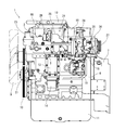
- both side portions parallel to the crankshaft 5 are referred to as left and right
- the flywheel housing 7 installation side is referred to as the front side
- the cooling fan 9 installation side is referred to as the rear side.
- these are used as a reference for the positional relationship between the four sides and the top and bottom of the diesel engine 1.
- an intake manifold 3 is arranged on one side parallel to the crankshaft 5 in the diesel engine 1 and an exhaust manifold 4 is arranged on the other side.
- the intake manifold 3 is formed integrally with the cylinder head 2 on the right side surface of the cylinder head 2, and the exhaust manifold 4 is installed on the left side surface of the cylinder head 2.
- the cylinder head 2 is mounted on a cylinder block 6 in which a crankshaft 5 and a piston (not shown) are built.
- the front and rear end sides of the crankshaft 5 are projected from both front and rear side surfaces of the cylinder block 6.
- a flywheel housing 7 is fixed to one side portion (in the embodiment, the front side surface of the cylinder block 6) that intersects the crankshaft 5 in the diesel engine 1.
- a flywheel 8 is disposed in the flywheel housing 7. The flywheel 8 is pivotally supported on the front end side of the crankshaft 5 and is configured to rotate integrally with the crankshaft 5. It is configured such that the power of the diesel engine 1 is taken out via a flywheel 8 to an operation part of a work machine (for example, a hydraulic excavator or a forklift).
- a work machine for example, a hydraulic excavator or a forklift
- a cooling fan 9 is provided on the other side of the diesel engine 1 that intersects the crankshaft 5 (in the embodiment, the rear side of the cylinder block 6). A rotational force is transmitted from the rear end side of the crankshaft 5 to the cooling fan 9 via the V belt 10.
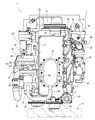
- An oil pan 11 is disposed on the lower surface of the cylinder block 6. Lubricating oil is stored in the oil pan 11. Lubricating oil in the oil pan 11 is sucked by an oil pump (not shown) disposed on the right side surface of the cylinder block 6 at a portion where the cylinder block 6 is connected to the flywheel housing 7. The oil is supplied to each lubricating part of the diesel engine 1 through an oil cooler 13 and an oil filter 14 arranged on the right side surface. The lubricating oil supplied to each lubricating part is then returned to the oil pan 11. The oil pump (not shown) is configured to be driven by rotation of the crankshaft 5.
- a fuel supply pump 15 for supplying fuel is attached to a connecting portion of the cylinder block 6 with the flywheel housing 7, and the fuel supply pump 15 is disposed below the EGR device 24.
- a common rail 16 is fixed to the side of the cylinder block 6 below the intake manifold 3 of the cylinder head 2 and is disposed above the fuel supply pump 15.
- injectors (not shown) for four cylinders each having an electromagnetic opening / closing control type fuel injection valve are provided.
- a fuel tank (not shown) mounted on the work vehicle is connected to each injector via a fuel supply pump 15 and a cylindrical common rail 16. Fuel in the fuel tank is pumped from the fuel supply pump 15 to the common rail 16, and high-pressure fuel is stored in the common rail 16. By opening and closing the fuel injection valves of the injectors, high-pressure fuel in the common rail 16 is injected from the injectors into the cylinders of the diesel engine 1.
- a blow-by gas reduction device that takes in the blow-by gas leaked from the combustion chamber of the diesel engine 1 or the like to the upper surface side of the cylinder head 2 on the upper surface of the head cover 18 that covers an intake valve and an exhaust valve (not shown) provided on the upper surface of the cylinder head 2. 19 is provided.
- a blow-by gas outlet of the blow-by gas reduction device 19 is communicated with an intake portion of the two-stage supercharger 30 via a reduction hose 68.
- the blow-by gas from which the lubricating oil component has been removed in the blow-by gas reduction device 19 is reduced to the intake manifold 3 via the two-stage supercharger 30.
- the engine starter 20 is attached to the flywheel housing 7, and the engine starter 20 is disposed below the exhaust manifold 4.
- the starter 20 for starting the engine is attached to the flywheel housing 7 at a position below the connecting portion between the cylinder block 6 and the flywheel housing 7.
- the cooling water pump 21 for cooling water lubrication is disposed below the cooling fan 9 at a portion on the left side of the rear surface of the cylinder block 6.
- the rotation of the crankshaft 5 drives the cooling water pump 21 together with the cooling fan 9 via the cooling fan driving V-belt 10.
- Cooling water in a radiator (not shown) mounted on the work vehicle is supplied to the cooling water pump 21 by driving the cooling water pump 21. Then, cooling water is supplied to the cylinder head 2 and the cylinder block 6 to cool the diesel engine 1.
- the cooling water pump 21 is disposed below the exhaust manifold 4, and the cooling water inlet pipe 22 communicating with the cooling water outlet of the radiator is located on the left side surface of the cylinder block 6 and at the same height as the cooling water pump 21. Fixed.
- a cooling water outlet pipe 23 communicating with the cooling water inlet of the radiator is fixed above the rear surface of the cylinder head 2.
- the cylinder head 2 has a cooling water drainage portion 35 protruding from the rear of the intake manifold 3, and a cooling water outlet pipe 23 is installed on the upper surface of the cooling water drainage portion 35.
- the inlet side of the intake manifold 3 is connected to an air cleaner (not shown) via a collector (EGR main body case) 25 of an EGR device 24 (exhaust gas recirculation device) described later.
- the fresh air (external air) sucked into the air cleaner is dust-removed and purified by the air cleaner, is sent to the intake manifold 3 through the collector 25, and is supplied to each cylinder of the diesel engine 1.
- the collector 25 of the EGR device 24 is connected to the right side of the intake manifold 3 that is integrally formed with the cylinder head 2 and constitutes the right side surface of the cylinder head 2.
- the outlet opening of the collector 25 of the EGR device 24 is connected to the inlet opening of the intake manifold 3 provided on the right side surface of the cylinder head 2.
- the collector 25 of the EGR device 24 is connected to an air cleaner via an intercooler (not shown) and the two-stage supercharger 30.
- the EGR device 24 mixes the recirculated exhaust gas of the diesel engine 1 (EGR gas from the exhaust manifold 4) and fresh air (external air from the air cleaner) and supplies the air to the intake manifold 3 as a collector 25.
- an EGR valve member 29 for communicating the collector 25.
- the EGR device 24 is disposed on the right side of the intake manifold 3 in the cylinder head 2. That is, the EGR device 24 is fixed to the right side surface of the cylinder head 2 and communicates with the intake manifold 3 in the cylinder head 2.
- the collector 25 is connected to the intake manifold 3 on the right side surface of the cylinder head 2
- the EGR gas inlet of the recirculation exhaust gas pipe 28 is connected to the front portion of the intake manifold 3 on the right side surface of the cylinder head 2 and fixed.
- an EGR valve member 29 and an intake throttle member 26 are connected to the front and rear of the collector 25, respectively, and an EGR gas outlet of the recirculated exhaust gas pipe 28 is connected to the rear end of the EGR valve member 29.
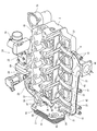
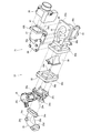
- the EGR cooler 27 is fixed to the front side surface of the cylinder head 2. Cooling water and EGR gas flowing through the cylinder head 2 flow into and out of the EGR cooler 27, and the EGR gas is cooled in the EGR cooler 27.
- EGR cooler connection pedestals 33 and 34 for connecting the EGR cooler 27 are projected on the front side surface of the cylinder head 2 at the left and right positions, and the EGR cooler 27 is connected to the connection pedestals 33 and 34. That is, the EGR cooler 27 is disposed at a position above the flywheel housing 7 and at a front position of the cylinder head 2 so that a rear end surface of the EGR cooler 27 and a front side surface of the cylinder head 2 are separated from each other.
- the two-stage supercharger 30 is disposed on the side of the exhaust manifold 4 (on the left side in the embodiment).
- the two-stage supercharger 30 includes a high pressure supercharger 51 and a low pressure supercharger 52.
- the high-pressure supercharger 51 includes a high-pressure turbine 53 incorporating a turbine wheel (not shown) and a high-pressure compressor 54 incorporating a blower wheel (not shown), and the low-pressure supercharger 52 is a turbine wheel (not shown).
- An exhaust gas inlet 57 of the high-pressure turbine 53 is connected to the exhaust manifold 4, and an exhaust gas inlet 60 of the low-pressure turbine 55 is connected to an exhaust gas outlet 58 of the high-pressure turbine 53 via a high-pressure exhaust gas pipe 59.
- An exhaust gas intake side end of an exhaust gas discharge pipe (not shown) is connected to the gas outlet 61.
- a fresh air supply side (new air outlet side) of an air cleaner (not shown) is connected to a fresh air intake port (fresh air inlet) 63 of the low pressure compressor 56 via an air supply pipe 62 to supply fresh air of the low pressure compressor 56.
- a fresh air intake port 66 of the high pressure compressor 54 is connected to a mouth (fresh air outlet) 64 via a low pressure fresh air passage tube 65, and a high pressure fresh air passage tube (not shown) is connected to a fresh air supply port 67 of the high pressure compressor 54.
- the fresh air intake side of the intercooler (not shown) is connected via
- the high pressure supercharger 51 is connected to the exhaust gas outlet 58 of the exhaust manifold 4 and fixed to the left side of the exhaust manifold 4, while the low pressure supercharger 52 connects the high pressure exhaust gas pipe 59 and the low pressure fresh air passage pipe 65. And is connected to the high-pressure supercharger 51 and fixed above the exhaust manifold 4. That is, the high-pressure supercharger 51 and the exhaust manifold 4 having a small diameter are juxtaposed on the left and right below the low-pressure supercharger 52 having a large diameter, so that the two-stage supercharger 30 is located on the left side surface of the exhaust manifold 4. And disposed so as to surround the upper surface. That is, the exhaust manifold 4 and the two-stage supercharger 30 are compactly fixed to the left side surface of the cylinder head 2 so as to be arranged in a rectangular shape when viewed from the back (front view).
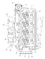
- the cylinder head 2 includes a plurality of intake passages 36 for introducing fresh air into a plurality of intake ports (not shown) and a plurality of exhaust passages for deriving exhaust gas from the plurality of exhaust ports. 37 is formed.
- An intake manifold 3 that collects a plurality of intake passages 36 is integrally formed on the right side of the cylinder head 2.
- the exhaust manifold 4 is connected to the left side opposite to the right side on which the intake manifold 3 is configured, and the EGR cooler 27 is connected to the front side (flywheel housing 7 side) adjacent to the left and right sides. Is done. Further, connecting bases (EGR cooler connecting bases) 33 and 34 connected to the EGR cooler 27 are formed so as to protrude from the front side surface of the cylinder head 2, and an EGR gas passage (EGR gas relay passage) is formed in the connecting bases 33 and 34. 31 and 32 and cooling water flow paths (cooling water relay flow paths) 38 and 39 are formed.
- the EGR gas relay passages 31 and 32 and the cooling water passages 38 and 39 are formed in the connection bases 33 and 34 to which the EGR cooler 27 is connected, so that the cooling water pipe and the EGR are provided between the EGR cooler 27 and the cylinder head 2.
- the cylinder head 2 includes an upstream EGR gas relay passage 31 that communicates from the front portion on the left side to the front side, and an EGR gas outlet 41 provided on the front end side of the exhaust manifold 4 has an upstream EGR gas relay passage 31. Communicated with.
- the cylinder head 2 includes a downstream EGR gas relay passage 32 that communicates from the front right side portion (front of the intake manifold 3) to the front side surface, and the EGR gas inlet of the recirculated exhaust gas pipe 28 is the downstream EGR. It communicates with the gas relay flow path 32.
- the cylinder head 2 includes EGR cooler coupling pedestals 33 and 34 projecting forward on the left and right edge sides (front left corner portion and front right corner portion of the cylinder head 2) of the front side surface.
- An upstream EGR gas relay flow path 31 is provided in the connection pedestal 33, and a downstream EGR gas relay flow path 32 is provided in the connection pedestal 34.
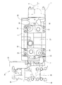
- the EGR device 24 is connected to the intake manifold 3 protruding from the right side surface of the cylinder head 2.
- the intake manifold 3 is provided near the rear side of the right side of the cylinder head 2 (on the side of the cooling fan 9), and is configured such that the lower side part of the right side of the cylinder head 2 protrudes to the right side.
- An intake inlet 40 is provided.
- the intake outlet 83 in the collector 25 of the EGR device 24 is connected to the intake inlet 40 of the intake manifold 3 protruding from the right side surface of the cylinder head 2, and the EGR device 24 is fixed to the right side of the cylinder head 2.
- a connecting pedestal 34 connected to the EGR cooler 27 is projected forward from the right side of the cylinder head 2 (on the flywheel housing 7 side).
- the downstream EGR gas relay channel 32 is provided on the right side of the connecting pedestal 34.
- the EGR gas outlet is open.
- one end of the recirculation exhaust gas pipe 28 of the EGR device 24 is connected to the right side surface of the connection base 34, so that the collector 25 of the EGR device 24 is connected via the recirculation exhaust gas pipe 28 and the EGR valve member 29.
- the downstream EGR gas relay flow path 32 in the cylinder head 2 communicates.
- a cooling water drainage portion (thermostat case) 35 that is open on the right side of the cylinder head 2 (on the cooling fan 9 side) and communicates with the cooling water outlet pipe (thermostat cover) 23 is provided projecting rearward.
- a thermostat (not shown) is installed inside. Since the cooling water drainage portion 35 is configured to be offset behind the right side surface of the cylinder head 2, the V belt 10 wound around the fan pulley 9 a to which the cooling fan 9 is fixed is placed below the cooling water drainage portion 35. The length of the diesel engine 1 in the front-rear direction can be shortened.
- the cooling water drainage part 35 also protrudes from the right side surface of the cylinder head 2, and the intake manifold 3 and the cooling water drainage part 35 are provided side by side on the right side surface of the cylinder head 2.
- a connecting pedestal 33 connected to the EGR cooler 27 is projected forward from the left side of the cylinder head 2 (on the flywheel housing 7 side).
- the upstream EGR gas relay passage 31 is provided on the left side of the connecting pedestal 33.
- the EGR gas inlet is open. That is, on the left side surface of the cylinder head 2, the EGR gas inlet of the upstream EGR gas relay passage 31 and the exhaust outlets of the plurality of exhaust passages 37 are opened side by side in the front-rear direction.
- the exhaust manifold 4 has an EGR gas outlet 41 communicating with the upstream EGR gas relay passage 31 and an exhaust inlet communicating with the plurality of exhaust passages 37 on the right side which is a connection surface with the left side of the cylinder head 2.
- the exhaust manifold 4 is provided with an exhaust collecting portion 43 communicating with the EGR gas outlet 41 and the exhaust inlet 42 so that the longitudinal direction is the front-rear direction.
- An exhaust outlet 44 communicating with the collecting portion 43 is opened.
- the exhaust manifold 4 when exhaust gas from the exhaust flow path 37 of the cylinder head 2 flows into the exhaust collecting portion 43 through the exhaust inlet 42, part of the exhaust gas becomes EGR gas, and from the EGR gas outlet 41 to the upstream of the cylinder head 2. Flows into the side EGR gas relay flow path 31, and the remainder of the exhaust gas flows into the two-stage supercharger 30 from the exhaust outlet 44.
- a pair of left and right EGR cooler connection pedestals 33 and 34 are provided on the exhaust manifold 4 side and the intake manifold 3 side, respectively.
- the EGR cooler connecting pedestal 33 is provided with an upstream EGR gas relay flow path 31 for communicating the EGR gas flow paths of the exhaust manifold 4 and the EGR cooler 27.
- the EGR cooler connection pedestal 34 is provided with a downstream EGR gas relay flow path 32 that allows the EGR gas flow paths of the EGR device 24 and the EGR cooler 27 to communicate with each other.
- the EGR cooler connection base 33 is provided with a downstream side cooling water flow path 38 through which cooling water is discharged from the EGR cooler 27.
- an upstream side cooling water flow path 39 for supplying cooling water to the EGR device 24 and the EGR cooler 27 is provided in the EGR cooler connection base 34.
- EGR gas piping for communicating the exhaust manifold 4, the EGR cooler 27, and the EGR device 24 is not required, and the connection location in the EGR gas flow path is reduced. Less. Therefore, in the diesel engine 1 that reduces NOx by EGR gas, not only can EGR gas leakage be reduced, but also deformation due to stress change due to expansion and contraction of the piping can be suppressed. In addition, since the EGR gas relay flow paths 31 and 32 and the cooling water flow paths 38 and 39 are formed in the EGR cooler connection bases 33 and 34, the shapes of the flow paths 31, 32, 38, and 39 that are formed in the cylinder head 2 are used. Therefore, the cylinder head 2 can be easily cast without using a complicated core.
- the EGR cooler connection pedestal 33 on the intake manifold 3 side and the EGR cooler connection pedestal 34 on the exhaust manifold 4 side are separated from each other, mutual influences due to thermal deformation in the connection pedestals 33 and 34 can be suppressed. Therefore, not only can gas leakage and breakage at the connecting portion between the EGR cooler connecting pedestals 33 and 34 and the EGR cooler 27 be prevented, but also the rigidity balance of the cylinder head 2 can be maintained. Further, since the volume on the front side of the cylinder head 2 can be reduced, the weight of the cylinder head 2 can be reduced. Further, since the EGR cooler 27 can be disposed away from the front side surface of the cylinder head 2 and a space is provided before and after the EGR cooler 27, the cooling air can flow around the EGR cooler 27. Therefore, the EGR cooler 27 The cooling efficiency can be improved.
- the EGR cooler connection pedestal 33 is provided with a downstream cooling water flow path 38 and an upstream EGR gas relay flow path 31 vertically, and the EGR cooler connection pedestal 34 has a downstream EGR gas relay flow path 32 and an upstream.
- the side cooling water flow path 39 is arranged vertically.
- the cooling water inlet of the downstream cooling water passage 38 and the EGR gas inlet of the downstream EGR gas relay passage 32 are arranged at the same height, while the cooling water outlet and the downstream EGR of the upstream cooling water passage 39 are arranged.
- the EGR gas outlet of the gas relay channel 32 is arranged at the same height.
- the EGR gas relay flow paths 31 and 32 and the cooling water flow paths 38 and 39 are provided in the separated EGR cooler connection bases 33 and 34, heat in both the EGR cooler connection bases 33 and 34 is obtained. The effect of deformation is reduced. Further, in the EGR cooler connection pedestals 33 and 34, the EGR gas flowing through the EGR gas relay flow paths 31 and 32 is cooled by the cooling water flowing through the cooling water flow paths 38 and 39, and the thermal deformation itself in the EGR cooler connection pedestals 33 and 34 is performed. Is also suppressed. Furthermore, in each of the EGR cooler connection pedestals 33 and 34, the EGR gas relay flow paths 31 and 32 and the cooling water flow paths 38 and 39 are arranged with their respective vertical height positions replaced. Therefore, the heat distribution in the EGR cooler connection pedestals 33 and 34 is upside down, and the influence of thermal deformation in the height direction in the cylinder head 2 can be reduced.
- the cylinder head 2 includes a spacer 46 that is connected to the peripheral edge of the lower surface of the head cover 18 by an outer peripheral wall erected upward from the peripheral edge of the upper surface.
- the spacer 46 includes a plurality of openings 47 on the right side surface, and a fuel pipe 48 that connects an injector (not shown) provided in the cylinder head 2 and the common rail 16 is passed through the opening 47. ing.
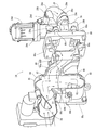
- the EGR device 24 includes a collector (main body case) 25 that mixes fresh air and EGR gas and supplies them to the intake manifold 3. And an intake throttle member 26 for introducing fresh air are connected to each other via a collector 25. An EGR valve member 29 connected to the outlet side of the recirculation exhaust gas pipe 28 is connected to the collector 25 in communication.
- the fresh air flow direction and the EGR gas flow direction intersect at an orthogonal or obtuse angle, and the direction in which the mixed gas of EGR gas and fresh air is taken into the intake manifold 3 is the fresh air flow direction and the EGR gas.
- the direction intersects each flow direction.
- a fresh air inlet 81 to which fresh air is supplied and an EGR gas inlet 82 to which EGR gas is supplied are opened by being distributed to both front and rear side surfaces of the collector 25, and an intake outlet 83 connected to the intake manifold 3 is provided. Opened on the left side of the collector 25.
- the EGR gas inlet 82 and the intake outlet 83 are arranged at the same height position, and the fresh air inlet 81 and the EGR gas inlet 82 are arranged at different height positions.
- fresh air introduced from the intake throttle member 26 to the fresh air inlet 81 flows while bending in an L shape from the front-rear direction to the vertical direction, while being introduced from the EGR valve member 29 to the EGR gas inlet 82.
- EGR gas flows obliquely upward. Therefore, the EGR gas flows in the direction in which the fresh air flows, and the EGR gas is easily mixed with the fresh air.
- a mixed gas of fresh air and EGR gas flows in an L shape from the vertical direction to the horizontal direction, and flows into the intake manifold 3 from the intake outlet 83.
- the mixing distribution of EGR gas into fresh air It can be made uniform.
- the EGR gas flow direction with respect to the fresh air flow direction is 90 ° or more, and the fresh air flow and the EGR gas flow intersect each other.
- the drift of EGR gas in the intake manifold 3 can be suppressed.
- the EGR gas concentration of the intake air supplied to each of the plurality of intake passages 36 in the cylinder head 2 can be made uniform, and variations in the combustion action of each cylinder in the diesel engine 1 can be suppressed.
- the generation of black smoke is suppressed, and the amount of NOx can be reduced while maintaining a good combustion state of the diesel engine 1. That is, the exhaust gas can be purified (cleaned) by the recirculation of the EGR gas without causing misfire in a specific cylinder.
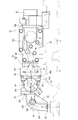
- the collector 25 is configured by connecting an upper case (first case) 84 having a fresh air inlet 81 and a lower case (second case) 85 having an EGR gas inlet 82 and an intake outlet 83.
- an upper case (first case) 84 having a fresh air inlet 81
- a lower case (second case) 85 having an EGR gas inlet 82 and an intake outlet 83.
- a downstream EGR gas passage (first EGR gas passage) 86a that is a part of the EGR gas passage 86 through which EGR gas flows, and a mixing chamber 87 for mixing fresh air and EGR gas are provided in the upper case 84.
- An upstream EGR gas flow channel (second EGR gas flow channel) 86b that communicates the downstream EGR gas flow channel 86a and the EGR gas inlet 82, and a mixed gas in which fresh air and EGR gas are mixed is introduced from the mixing chamber 87 into the intake manifold. 3 is provided in the lower case 85.
- the lower case 85 is provided with the EGR gas inlet 82 and the upper case 84 is provided with the fresh air inlet 81 and the mixing chamber 87, the fresh air flowing from the fresh air inlet 81 and the lower case 85 are mixed in the mixing chamber 87.
- the EGR gas flowing in from the air flows so as to cross each other, and the fresh air and the EGR gas are efficiently mixed.
- the intake air outlet 83 is provided in the lower case 85 so that fresh air flowing into the upper case 84 tends to flow toward the lower case 85, so that new EGR gas flowing toward the upper case 84 can be obtained. Mixing into the air is made uniform.
- each of the EGR gas flow path 86, the mixing chamber 87, and the mixed gas flow path 88 can be configured compactly in the collector 25, and the collector 25 can be downsized.
- the downstream EGR gas flow path 86a is connected to the side surface (left side) opposite to the side surface (left side surface) where the intake outlet 83 is provided with respect to the central axis of the mixing chamber 87, and is connected downstream.
- the side EGR gas flow path 86a and the upstream side EGR gas flow path 86b communicate with each other, and the EGR gas flow path 86 is formed in a spiral shape. That is, the EGR gas flow path 86 formed by the downstream EGR gas flow path 86a and the upstream EGR gas flow path 86b is curved so as to swell toward the opposite side (right side) to the intake outlet 83 in plan view.
- the bottom of the upstream EGR gas flow path 86b is formed by an inclined surface (an inclined surface toward the rear upper side) from the EGR gas inlet 82 toward the upper case 84.
- the EGR gas flowing into the mixing chamber 87 is guided by the flow of fresh air and reaches the intake outlet 83.
- EGR gas can be uniformly mixed with fresh air.
- the EGR gas flowing into the mixing chamber 87 from the EGR gas flow path 86 flows in a direction opposite to the flow from the mixing chamber 87 toward the mixed gas flow path 88, the fresh air and the EGR gas are mutually exchanged in the mixing chamber 87. It will flow like a collision, and the EGR gas will be smoothly mixed with fresh air.
- the EGR gas flows along the spiral EGR gas flow path 86, the EGR gas becomes a swirl flow that forms a clockwise vortex and flows into the mixing chamber 87. Since the EGR gas disturbed in this way flows in a direction against the flow of the fresh gas, the EGR gas is smoothly mixed with the fresh air flowing in the interior simultaneously with the inflow into the mixing chamber 87. Accordingly, in the collector 25, fresh air and EGR gas can be efficiently mixed while being stirred before being sent to the intake manifold 3 (the EGR gas can be smoothly dispersed in the mixed gas), and the gas mixing state in the collector 25 Variation (unevenness) can be more reliably suppressed.
- the gas mixture with less unevenness can be distributed to each cylinder of the diesel engine 1 to suppress variations in the amount of EGR gas between the cylinders. Therefore, the generation of black smoke is suppressed and the combustion state of the diesel engine 1 is reduced. The amount of NOx can be reduced while maintaining good.
- the EGR gas flow path 86 is formed in a spiral shape, the EGR gas flowing into the mixing chamber 87 is given sufficient swirlability, so that the length of the collector 25 in the front-rear direction can be reduced.
- the lower surface flange 84a of the upper case 84 and the upper surface flange 85a of the lower case 85 are bolted together to open openings (new air inlet 81, EGR gas inlet 82, and intake outlet 83) in three directions (front and rear direction and left direction). ) Is configured.
- a fresh air outlet of the intake throttle member 26 is bolted to a rear flange 84 b that opens the fresh air inlet 81.
- the intake throttle member 26 adjusts the amount of fresh air supplied to the collector 25 by adjusting the opening degree of an intake valve (butterfly valve) 26 a inside the intake throttle member 26.
- the EGR gas outlet of the EGR valve member 29 is bolted to the front flange 85 b that opens the EGR gas inlet 82 via a rectangular tubular relay flange 89.
- the EGR valve member 29 adjusts the supply amount of EGR gas to the collector 25 by adjusting the opening degree of an EGR valve (not shown) in the EGR valve member 29.
- a reed valve 90 to be inserted into the EGR gas inlet 82 is fixed inside the front flange 85 b of the lower case 85.
- a relay flange (spacer) 89 bolted to the front flange 85 b covers the front of the reed valve 90, so that the collector 25 includes a reed valve 90 on the EGR gas inlet 82 side of the EGR gas flow path 86. To do.
- the relay flange 89 has an EGR gas outlet 89 a communicating with the EGR gas inlet 82 on the rear surface connected to the collector 25.
- Valve connecting seats 89 b and 89 c that connect to the EGR valve member 29 protrude from the front surface of the relay flange 89, and the openings of the valve connecting seats 89 b and 89 c communicate with the EGR gas outlet of the EGR valve member 29.
- the EGR gas is merged with the EGR gas inlets in the upper and lower valve coupling seats 89b and 89c, and flows into the EGR gas flow path 86 in the collector 25 from the EGR gas inlet 82 through the reed valve 90.
- the EGR valve member 29 is provided with an EGR valve (not shown) in an EGR gas passage 29f provided in the valve main body 29e, and an actuator 29d for adjusting the opening degree of the EGR valve is provided above the valve main body 29e. Is connected to the front side of the collector 25 via the relay flange 89.
- the EGR valve member 29 is provided with outlet side flanges 29a and 29b which are connected to the valve connection seats 89b and 89c of the relay flange 89 on the rear surface of the lower valve body 29e.
- the front surface of the EGR valve member 29 is provided with an inlet-side flange 29 c having an EGR gas inlet communicating with the EGR gas outlet of the recirculation exhaust gas pipe 28.
- the EGR valve member 29 is configured such that the EGR gas cooled by the EGR cooler 27 passes through the EGR gas relay passage 32 on the downstream side of the EGR cooler connection pedestal 34 and the recirculation exhaust gas pipe 28 to the EGR gas inlet of the inlet side flange 29c.
- the EGR gas is distributed up and down through the EGR gas passage 29f of the valve body 29e.
- the EGR gas that has flowed up and down through the EGR gas flow path 29f is adjusted in flow rate by the EGR valve, and flows into the relay flange 89 from the EGR gas outlets at the upper and lower outlet side flanges 29a and 29b.
- the recirculated exhaust gas pipe 28 has a gas pipe portion 28a bent in an L shape in plan view and a flat rib 28b protruding from the inner peripheral side of the outer wall of the gas pipe portion 28a.
- the recirculation exhaust gas pipe 28 is provided with an outlet side flange 28c connected to the inlet side flange 29c of the EGR valve member 29 at one end (rear end) of the gas pipe portion 28a, and connected to the right side surface of the EGR cooler connection base 34.
- the inlet side flange 28d is provided at the other end (left end) of the gas pipe portion 28a.
- the recirculated exhaust gas pipe 28 is provided with a sensor mounting seat 28e for mounting an EGR gas temperature sensor on the upper surface of the bent portion of the gas pipe portion 28a.
- the EGR device 24 can be configured to shorten the length of the collector 25, the distance between the EGR valve member 29 and the intake throttle member 26 can be shortened, and as a result, the front and rear length of the EGR device 24 can be configured to be short. Further, since the EGR valve member 29 has a configuration in which the actuator 29d is provided above, the uppermost portions of the EGR valve member 29, the collector 25, and the intake throttle member 26 can have the same height. Not only can the height be reduced, but also the left and right width of the EGR device 24 can be reduced.
- the EGR device 24 since the EGR device 24 is configured in a compact manner, the EGR device 24 can be easily connected only by adjusting the recirculated exhaust gas pipe 28 in the right direction of the cylinder head 2 integrally formed with the intake manifold 3. Contributes to downsizing.
- the recirculated exhaust gas pipe 28 Since the recirculated exhaust gas pipe 28 has a configuration in which flat ribs 28b are connected so as to connect both ends of the gas pipe portion 28a, the recirculated exhaust gas pipe 28 is configured with high rigidity, and the cylinder head. 2, the support strength on the front end side of the EGR device 24 is also increased. Further, since the recirculated exhaust gas pipe 28 has a configuration in which a flat rib 28b is provided along the EGR gas flow path 28f in the gas pipe portion 28a, the heat radiation area in the gas pipe portion 28a is widened by the rib 28b. Therefore, the cooling effect of the EGR gas flowing through the EGR gas flow path 28f is enhanced. As a result, it contributes to the cooling of the mixed gas purified by the EGR device 24, and it is easy to maintain the NOx amount reduction effect by the mixed gas in an appropriate state.
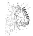
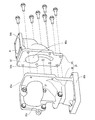
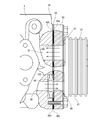
- the EGR cooler 27 includes a heat exchanging portion 91 in which cooling water passages and EGR gas passages are alternately stacked, and one side surface of the heat exchanging portion 91.
- a pair of left and right flange portions 92 and 93 provided at both left and right end portions are provided.
- the cooling water outlet 94 and the cooling water inlet 95 are provided separately on the left and right flange portions 92 and 93, while the EGR gas inlet 96 and the EGR gas outlet 97 are provided on the left and right flange portions 92 and 93.
- left and right flange portions 92 and 93 are connected to the front side surface of the cylinder head 2, and the EGR cooler 27 is fixed to the cylinder head 2.
- each flange portion 92, 93 By providing an opening portion for cooling water and an opening portion for EGR gas in each of the pair of left and right flange portions 92, 93, not only can each flange portion 92, 93 be constituted by a common member, but also flanges The material cost concerning the parts 92 and 93 can be suppressed. Further, since the flange portions 92 and 93 are formed by drilling through holes 94 to 97 for cooling water and EGR gas in flat plates for connection to the cylinder head 2, manufacture in the EGR cooler 27 is easy. It is.
- connection part of the flange parts 92 and 93 and the heat exchange part 91 can be comprised at the minimum, the amount of heat transmitted from the cylinder head 2 to the heat exchange part 91 can be reduced, and the EGR gas in the heat exchange part 91 can be reduced. Increase cooling effect.
- the EGR cooler 27 has a configuration in which the flange portions 92 and 93 are protruded from the rear surface of the heat exchange portion 91, so that a space is formed between the heat exchange portion 91 and the cylinder head 2. Therefore, since the EGR cooler 27 is in a state where a wide range of the front and rear surfaces of the heat exchanging portion 91 is exposed to the outside air and is also dissipated from the heat exchanging portion 91, the cooling effect of the EGR gas in the EGR cooler 27 is enhanced.
- the number of stacked layers in the heat exchange unit 91 can be reduced, and the front-rear length of the EGR cooler 27 can be shortened, so that the diesel engine 1 can be downsized. .
- the left flange portion 92 is provided with a cooling water outlet 94 and an EGR gas inlet 96
- the right flange portion 93 is provided with a cooling water inlet 95 and an EGR gas outlet 97.
- the cooling water outlet 94 and the EGR gas inlet 96 are provided vertically
- the EGR gas outlet 97 and the cooling water inlet 95 are provided vertically.
- the cooling water outlet 94 and the EGR gas outlet 97 are arranged at the same height
- the cooling water inlet 95 and the EGR gas inlet 96 are arranged at the same height.
- the left and right flange portions 92 and 93 of the EGR cooler 27 are connected to the EGR cooler connection bases 33 and 34 formed so as to protrude from the front side surface of the cylinder head 2.
- the upstream EGR gas relay flow path 31 and the downstream cooling water relay flow path 38 in the left EGR cooler connection pedestal 33 communicate with the EGR gas inlet 96 and the cooling water outlet 94 of the left flange 92, respectively, and the right EGR cooler.
- the downstream EGR gas relay flow path 32 and the upstream cooling water relay flow path 39 in the connection base 34 respectively communicate with the EGR gas outlet 97 and the cooling water inlet 95 of the right flange portion 93.
- connection bases 33 and 34 to which the flange portions 92 and 93 of the EGR cooler 27 are connected are provided with the EGR gas relay passages 31 and 32 and the cooling water passages 38 and 39, respectively, and the EGR gas inlet 96 and the outlet are provided at the flange portions 92 and 93. 97 is in communication with the cooling water outlet 94 and the inlet 95. Therefore, it is not necessary to provide a cooling water pipe and an EGR gas pipe between the EGR cooler 27 and the cylinder head 2. Accordingly, it is possible to ensure the sealing performance at the connecting portion between the EGR cooler 27 and the cylinder head 2 without being affected by the expansion and contraction of the piping due to EGR gas or cooling water, and the EGR cooler 27 is externally exposed to heat or vibration. The resistance to the fluctuation elements is improved, and the cylinder head 2 can be installed compactly.
- the flange portion 92 is provided with the cooling water outlet 94 and the EGR gas inlet 96 above and below
- the flange portion 93 is provided with the EGR gas outlet 97 and the cooling water inlet 95 above and below, so that the flange portions 92 and 93 having the same shape are provided.
- they are attached to the heat exchanging portion 91 by turning them upside down. For this reason, the types of parts constituting the EGR cooler 27 can be reduced, the assemblability of the EGR cooler 27 is improved, and the parts cost is reduced.
- the flange portion 92 is provided with a cooling water outlet 94 and an EGR gas inlet 96 through which the cooling water or EGR gas having a large amount of heat passes, while the cooling water or EGR gas having a small amount of heat passes through the flange portion 93.
- a cooling water inlet 95 and an EGR gas outlet 97 are provided. Therefore, not only the distortion due to thermal deformation in each of the flange portions 92 and 93 is suppressed, but the flange portions 92 and 93 are configured as separate bodies and are less influenced by the mutual thermal deformation. Failure can be prevented.
- the cooling water outlet 94 and the cooling water inlet 95 are diagonally arranged in the rear view, and the EGR gas inlet 96 and the EGR gas outlet 97 are diagonally arranged. Since each of the EGR gas and the cooling water having different heat amounts are supplied or discharged from the diagonal position, thermal deformation at the connecting portion between the EGR cooler 27 and the cylinder head 2 is alleviated to suppress bending and loosening of the connecting portion. it can. Therefore, it is possible not only to prevent leakage of EGR gas and cooling water in the EGR cooler 27 and the cylinder head 2, but also to prevent a decrease in connection strength.
- a plate-shaped gasket 98 is sandwiched between the cylinder head 2 and the flange portions 92 and 93 so that the left and right flange portions 92 and 93 are installed.
- An O-ring 99 which is a ring-shaped seal member is embedded in each of the cooling water inlet and the cooling water outlet in the cylinder head 2 communicating with the cooling water outlet 94 and the cooling water inlet 95 in the flange portions 92 and 93, respectively. Covered with flange portions 92 and 93.
- the O-ring 99 is embedded in the space formed by the cooling water inlet and the cooling water outlet and the rear end surfaces of the flange portions 92 and 93 in the coupling bases 33 and 34 of the cylinder head 2, the cooling water flows.
- the connecting portions of the connecting pedestals 33 and 34 and the flange portions 92 and 93 come into contact with the O-ring 99, and the sealing performance (sealing performance) of the connecting portion at the cooling water inlet / outlet can be ensured. Therefore, even if the EGR cooler 27 that flows in and out of the liquid and gas is connected to the cylinder head 2, the sealing performance in each of the liquid and the gas can be secured, and the leakage of each of the EGR gas and the cooling water can be prevented.
- a through hole 100 for fastening a bolt is formed in the outer peripheral portion of the flange portions 92 and 93 and on the outer side position. That is, the left flange portion 92 has five through holes 100 on the top and bottom and the left side, and the right flange portion 93 has five through holes 100 on the top and bottom and the right side. Accordingly, the left flange portion 92 is provided with a through hole 100 on the upper side of the cooling water outlet 94, on the lower side of the EGR gas inlet 96, and on the left side between the cooling water outlet 94 and the EGR gas inlet 96. When the second connection base 33 is bolted, the sealing performance at the cooling water outlet 94 and the EGR gas inlet 96 is ensured.
- the right flange portion 93 is provided with a through hole 100 on the lower side of the cooling water inlet 95, the upper side of the EGR gas outlet 97, and the right side between the cooling water inlet 95 and the EGR gas outlet 97, thereby When bolted to the connection base 34 of the head 2, sealing performance at the cooling water inlet 95 and the EGR gas outlet 97 is ensured.
- the gasket 98 is configured by bonding two plates 98a and 98b provided with through holes 101 to 103, and the EGR gas passes through the through hole (through hole for EGR gas) 101, and the through hole (cooling water) The cooling water passes through the through-hole (102), and the fastening bolt is inserted into the through-hole (through-hole for bolt) 103.
- the gasket 98 has a shape branched so that the inner peripheral edge of the EGR gas through hole 101 warps back and forth, and the opening area of the cooling water through hole 102 is larger than the opening areas of the cooling water inlets and outlets 94 and 95. Is also configured to be wide.
- the gasket 98 causes the inner peripheral edge of the EGR gas through hole 101 of the front side plate 98a to warp forward, while the inner peripheral edge of the rear plate 98b of the EGR gas through hole 101 returns to the rear side.
- the inner peripheral edge of the EGR gas through hole 101 becomes a Y-shaped cross section.
- the gasket 98 is configured such that the opening of the cooling water through hole 102 is wider than the cooling water inlets and outlets 94 and 95, whereby the O-ring 99 is inserted into the cooling water through hole 102. That is, the O-ring 99 in which the communicating portion between the cooling water inlet / outlet of the flange portions 92 and 93 and the cooling water relay passages 38 and 39 in the connection bases 33 and 34 is fitted in the cooling water through hole 102 of the gasket 98. Sealed.
- the connecting pedestals 33 and 34 of the cylinder head 2 are opened larger than the flow path diameters of the coolant relay passages 38 and 39 in the connecting pedestals 33 and 34 by opening the cooling water inlets and outlets with steps.
- the O-ring 99 is fitted to the outer peripheral side of the coolant relay passages 38 and 39 with respect to the coolant inlet / outlet of the coupling bases 33 and 34. That is, the O-ring 99 is inserted into the gasket 98 and is fitted into the stepped portion of the cooling water inlet / outlet in the connection bases 33 and 34 and is held between the connection bases 33 and 34 and the flange portions 92 and 93.
- the O-ring 99 is deformed so as to spread outward, and is brought into close contact with the coupling bases 33 and 34 and the flange portions 92 and 93. , Ensure the sealing of cooling water.
- the ring-shaped O-ring 99 has a shape in which the inner peripheral portion swells back and forth, and the front and rear edges of the inner peripheral portion protrude forward and backward by being pressed by cooling water passing through the inner peripheral portion of the O-ring. Deform to Thereby, since the inner peripheral part of O-ring 99 closely_contact
- the ring-shaped O-ring 99 has a shape in which an inner peripheral portion is swelled back and forth, and a concave portion is provided on the inner peripheral surface thereof. That is, by configuring the inner peripheral surface of the O-ring 99 with a Y-shaped cross section bent back and forth, the front and rear edges of the inner peripheral portion are pressed by the cooling water passing through the inner peripheral portion of the O-ring. This further protrudes back and forth, and improves the adhesion between the inner peripheral portion of the O-ring 99 and the connecting pedestals 33 and 34 and the flange portions 92 and 93. Accordingly, the cooling water at the connecting portion between the cylinder head 2 and the EGR cooler 27 is increased. Can improve the sealing performance.
Landscapes
- Engineering & Computer Science (AREA)
- Chemical & Material Sciences (AREA)
- Combustion & Propulsion (AREA)
- Mechanical Engineering (AREA)
- General Engineering & Computer Science (AREA)
- Exhaust-Gas Circulating Devices (AREA)
- Cylinder Crankcases Of Internal Combustion Engines (AREA)
Abstract
Description
2 シリンダヘッド
3 吸気マニホールド
4 排気マニホールド
5 クランク軸
6 シリンダブロック
7 フライホイールハウジング
8 フライホイール
9 冷却ファン
24 EGR装置
25 コレクタ(EGR本体ケース)
26 吸気スロットル部材
27 EGRクーラ
28 再循環排気ガス管
29 EGRバルブ部材
31 上流側EGRガス中継流路
32 下流側EGRガス中継流路
33 EGRクーラ連結台座
34 EGRクーラ連結台座
35 冷却水排水部
36 吸気流路
37 排気流路
38 下流側冷却水中継流路
39 上流側冷却水中継流路
40 吸気入口
91 熱交換部
92 フランジ部
93 フランジ部
94 冷却水出口
95 冷却水入口
96 EGRガス入口
97 EGRガス出口
98 ガスケット
98a 前側板
98b 後側板
99 Oリング
100 貫通穴(ボルト締結用)
101 EGRガス用貫通穴
102 冷却水用貫通穴
103 ボルト用貫通穴
Claims (10)
- シリンダヘッドの左右両側に振り分けられて配置される排気マニホールド及び吸気マニホールドと、前記排気マニホールドから排出される排気ガスの一部をEGRガスとして前記吸気マニホールドに還流させるEGR装置と、前記EGRガスを冷却して前記EGR装置に供給するEGRクーラとを備えるエンジン装置であって、
前記EGRクーラは、冷却水流路とEGRガス流路とが交互に積層された熱交換部と、熱交換部の一側面における左右両端部分に設けられた左右一対のフランジ部とを備え、前記冷却水の入口と出口が左右の前記フランジ部に振り分けて設けられる一方、前記EGRガスの入口と出口が左右の前記フランジ部に振り分けて設けられ、前記シリンダヘッドの前後側面の一方に左右の前記フランジ部が連結されていることを特徴とするエンジン装置。 - 前記EGRクーラにおける前記熱交換部と前記シリンダヘッドの間に空間が構成されることを特徴とする請求項1に記載のエンジン装置。
- 前記左右のフランジ部の一方に、前記冷却水の入口と前記EGRガスの出口が設けられる一方、前記左右のフランジ部の他方に、前記冷却水の出口と前記EGRガスの入口が設けられ、
前記冷却水の入口及び前記EGRガスの出口と、前記冷却水の出口及び前記EGRガスの入口とが前記フランジ部で上下に設けられており、前記冷却水の入口と前記EGRガスの入口とが同一高さに配置される一方、前記冷却水の出口と前記EGRガスの出口とが同一高さに配置されることを特徴とする請求項1に記載のエンジン装置。 - 前記シリンダヘッドは、前記排気マニホールドが配置される側面から前記EGRクーラが配置される側面に連通された上流側EGR流路と、前記吸気マニホールドが配置される側面から前記EGRクーラが配置される側面に連通された下流側EGR流路と、前記冷却水の入口と連通する上流側冷却水流路と、前記冷却水の出口と連通する下流側冷却水流路とを備えており、前記上流側EGR流路近傍に前記下流側冷却水流路が設けられる一方で、前記下流側EGR流路近傍に前記上流側冷却水流路が設けられることを特徴とする請求項3に記載のエンジン装置。
- 板状のガスケットが、前記左右のフランジ部を架設するようにして、前記シリンダヘッドと前記フランジ部との間に挟持されており、前記フランジ部における前記冷却水の入口及び出口それぞれと連通する前記シリンダヘッドにおける前記冷却水の出口及び入口それぞれにリング状のシール部材が埋設され、前記シール部材が、前記フランジ部で覆われていることを特徴とする請求項1に記載のエンジン装置。
- 前記EGR装置が、前記新気と前記EGRガスを混合して前記吸気マニホールドに供給する本体ケースを備えており、前記本体ケース内において、新気流れ方向と前記EGRガス流れ方向とが直交又は鈍角を形成して交わり、EGRガスと新気との混合ガスを前記吸気マニホールドに吸気させる方向が前記新気流れ方向及び前記EGRガス流れ方向それぞれと交差する方向となることを特徴とする請求項1に記載のエンジン装置。
- 新気が供給される新気入口と、前記EGRガスが供給されるEGRガス入口とが前記本体ケースの前後両側面に振り分けて開口されるとともに、前記吸気マニホールドと連結する吸気出口が前記本体ケースの左右両側面の一方に開口され、前記吸気出口と前記EGRガス入口が同一高さ位置に配置されるとともに、前記新気入口と前記EGRガス入口が異なる高さ位置に配置されることを特徴とする請求項6に記載のエンジン装置。
- 前記本体ケースが、前記新気入口を有する第1ケースと、前記吸気出口と前記EGRガス入口とを有する第2ケースとが連結されて構成されることを特徴とする請求項7に記載のエンジン装置。
- 前記EGRガスが流れるEGRガス流路の一部である第1EGRガス流路と、新気と前記EGRガスを混合する混合室とが、前記第1ケースに設けられており、
前記第1EGRガス流路と前記EGRガス入口とを連通させる第2EGRガス流路と、新気と前記EGRガスが混合された混合ガスを前記混合室から前記吸気マニホールドに供給する混合ガス流路とが、前記第2ケースに設けられていることを特徴とする請求項8に記載のエンジン装置。 - 前記第1EGRガス流路が、前記混合室の中心軸に対して前記吸気出口の設けられた側面と反対側の側面側にオフセットして連結しており、
前記第1EGRガス流路と前記第2EGRガス流路とが連通されて、EGRガス流路が螺旋状に構成されていることを特徴とする請求項9に記載のエンジン装置。
Priority Applications (5)
| Application Number | Priority Date | Filing Date | Title |
|---|---|---|---|
| CN201780003149.7A CN108884791B (zh) | 2016-03-29 | 2017-03-13 | 发动机装置 |
| KR1020187011574A KR101970930B1 (ko) | 2016-03-29 | 2017-03-13 | 엔진 장치 |
| EP17774244.2A EP3438438B1 (en) | 2016-03-29 | 2017-03-13 | Engine device |
| US16/088,796 US10626833B2 (en) | 2016-03-29 | 2017-03-13 | Engine device |
| US16/848,096 US11035327B2 (en) | 2016-03-29 | 2020-04-14 | Engine device |
Applications Claiming Priority (4)
| Application Number | Priority Date | Filing Date | Title |
|---|---|---|---|
| JP2016-066824 | 2016-03-29 | ||
| JP2016066823A JP2017180227A (ja) | 2016-03-29 | 2016-03-29 | エンジン装置 |
| JP2016-066823 | 2016-03-29 | ||
| JP2016066824A JP6442429B2 (ja) | 2016-03-29 | 2016-03-29 | エンジン装置 |
Related Child Applications (2)
| Application Number | Title | Priority Date | Filing Date |
|---|---|---|---|
| US16/088,796 A-371-Of-International US10626833B2 (en) | 2016-03-29 | 2017-03-13 | Engine device |
| US16/848,096 Continuation US11035327B2 (en) | 2016-03-29 | 2020-04-14 | Engine device |
Publications (1)
| Publication Number | Publication Date |
|---|---|
| WO2017169700A1 true WO2017169700A1 (ja) | 2017-10-05 |
Family
ID=59964257
Family Applications (1)
| Application Number | Title | Priority Date | Filing Date |
|---|---|---|---|
| PCT/JP2017/010037 Ceased WO2017169700A1 (ja) | 2016-03-29 | 2017-03-13 | エンジン装置 |
Country Status (5)
| Country | Link |
|---|---|
| US (2) | US10626833B2 (ja) |
| EP (1) | EP3438438B1 (ja) |
| KR (1) | KR101970930B1 (ja) |
| CN (1) | CN108884791B (ja) |
| WO (1) | WO2017169700A1 (ja) |
Cited By (2)
| Publication number | Priority date | Publication date | Assignee | Title |
|---|---|---|---|---|
| WO2018139003A1 (ja) * | 2017-01-30 | 2018-08-02 | ヤンマー株式会社 | エンジン装置 |
| US20200325885A1 (en) * | 2017-11-16 | 2020-10-15 | Kabushiki Kaisha Kobe Seiko Sho (Kobe Steel, Ltd.) | Piping member and fluid transport device |
Families Citing this family (6)
| Publication number | Priority date | Publication date | Assignee | Title |
|---|---|---|---|---|
| JP6871845B2 (ja) * | 2017-12-15 | 2021-05-19 | ヤンマーパワーテクノロジー株式会社 | シリンダヘッド及びエンジン |
| JP7196755B2 (ja) | 2019-04-26 | 2022-12-27 | スズキ株式会社 | 車両用エンジン |
| WO2020162640A1 (ja) | 2020-02-17 | 2020-08-13 | 株式会社小松製作所 | シリンダヘッド及びエンジン |
| CN112282982B (zh) * | 2020-10-29 | 2022-08-19 | 东风商用车有限公司 | 天然气发动机用文丘里式混合器 |
| US11454157B2 (en) * | 2020-12-11 | 2022-09-27 | Caterpillar Inc. | Engine system with coolant collector |
| CN115628161B (zh) * | 2022-11-16 | 2025-12-05 | 中车戚墅堰机车有限公司 | 一种集成散热风道和egr支架的分体式飞轮壳 |
Citations (7)
| Publication number | Priority date | Publication date | Assignee | Title |
|---|---|---|---|---|
| JP2005133981A (ja) * | 2003-10-28 | 2005-05-26 | Mitsubishi Fuso Truck & Bus Corp | 排気熱交換器 |
| JP2007292012A (ja) * | 2006-04-27 | 2007-11-08 | Nissan Motor Co Ltd | 内燃機関の排気還流装置 |
| JP2011127537A (ja) * | 2009-12-18 | 2011-06-30 | Toyota Motor Corp | 排気冷却器および内燃機関の排気再循環装置 |
| GB2487591A (en) * | 2011-01-28 | 2012-08-01 | Gm Global Tech Operations Inc | An EGR cooler located in an air intake manifold |
| JP2012172534A (ja) * | 2011-02-17 | 2012-09-10 | Tokyo Roki Co Ltd | Egrクーラ |
| JP2013019279A (ja) * | 2011-07-07 | 2013-01-31 | Yanmar Co Ltd | エンジンの排気再循環装置 |
| JP2015001349A (ja) * | 2013-06-17 | 2015-01-05 | マルヤス工業株式会社 | 多管式熱交換器 |
Family Cites Families (34)
| Publication number | Priority date | Publication date | Assignee | Title |
|---|---|---|---|---|
| US4267812A (en) * | 1979-10-09 | 1981-05-19 | Ford Motor Company | Engine EGR cooler |
| US4258687A (en) * | 1979-10-09 | 1981-03-31 | Ford Motor Company | Engine with integral mounted EGR cooler |
| JP2000008969A (ja) | 1998-06-22 | 2000-01-11 | Nissan Diesel Motor Co Ltd | Egr装置 |
| JP4071370B2 (ja) | 1998-09-10 | 2008-04-02 | ヤマハ発動機株式会社 | 筒内噴射式エンジン用egr弁装置 |
| JP3852255B2 (ja) | 1999-11-10 | 2006-11-29 | いすゞ自動車株式会社 | Egr及びオイルの冷却装置 |
| DE10119484B4 (de) * | 2001-04-20 | 2018-01-04 | Bayerische Motoren Werke Aktiengesellschaft | Flüssigkeitsgekühlte Brennkraftmaschine mit einem Abgasrückführsystem |
| DE10153033B4 (de) * | 2001-10-26 | 2018-03-01 | Bayerische Motoren Werke Aktiengesellschaft | Abgas-Rückführ-Wärmetauscher für eine flüssigkeitsgekühlte Brennkraftmaschine |
| DE102005031300B4 (de) * | 2005-07-05 | 2021-05-12 | Daimler Ag | Brennkraftmaschine mit Kühlsystem und Abgasrückführsystem |
| JP4484800B2 (ja) | 2005-09-28 | 2010-06-16 | 株式会社クボタ | エンジン |
| EP1941224A1 (de) | 2005-10-20 | 2008-07-09 | Behr GmbH & Co. KG | Wärmetauscher |
| KR101298382B1 (ko) * | 2006-07-03 | 2013-08-20 | 모다인 매뉴팩츄어링 컴파니 | Egr 쿨러 |
| EP2077387B1 (de) * | 2008-01-07 | 2011-07-27 | Ford Global Technologies, LLC | Verfahren zur Kühlung eines rückzuführenden Abgasstroms einer Brennkraftmaschine |
| US20100224173A1 (en) * | 2009-03-09 | 2010-09-09 | Herve Palanchon | Heat Exchanger with Cast Housing and Method of Making Same |
| CN201420627Y (zh) * | 2009-04-29 | 2010-03-10 | 临海市邦得利汽车环保技术有限公司 | 柴油机egr冷却器 |
| JP5387612B2 (ja) * | 2010-06-25 | 2014-01-15 | マツダ株式会社 | エンジンの排気還流装置 |
| US10016856B2 (en) * | 2010-12-16 | 2018-07-10 | Eugene Neal | Method of rebuilding an EGR cooler |
| JP5578367B2 (ja) * | 2011-01-27 | 2014-08-27 | アイシン精機株式会社 | エンジンの吸気装置 |
| EP2674604A4 (en) * | 2011-02-08 | 2014-01-29 | Toyota Motor Co Ltd | Exhaust circulation device for internal combustion engine |
| JP5904108B2 (ja) * | 2011-12-19 | 2016-04-13 | 株式会社デンソー | 排気熱交換装置 |
| CN104114830B (zh) * | 2012-01-20 | 2017-09-08 | 洋马株式会社 | 船用发动机 |
| FR2986745A1 (fr) | 2012-02-15 | 2013-08-16 | Peugeot Citroen Automobiles Sa | Support moteur integrant un conduit de recirculation des gaz d'echappement, culasse adaptee et vehicule correspondant |
| JP2013177818A (ja) | 2012-02-28 | 2013-09-09 | Daihatsu Motor Co Ltd | Egr通路構造 |
| CN102619648B (zh) * | 2012-03-21 | 2014-06-04 | 浙江银轮机械股份有限公司 | 一种具有隔热功能的板翅式egr冷却器 |
| US20150136369A1 (en) * | 2012-06-08 | 2015-05-21 | International Engine Intellectual Property Company Llc | Egr cooler header casting |
| US20150021004A1 (en) * | 2013-07-18 | 2015-01-22 | International Engine Intellectual Property Company Llc | EGR Cooler |
| KR101490963B1 (ko) * | 2013-12-11 | 2015-02-06 | 현대자동차 주식회사 | 터보차저를 갖는 엔진시스템 |
| KR101583889B1 (ko) * | 2013-12-20 | 2016-01-21 | 현대자동차주식회사 | 차량의 오일온도 조절장치 및 그 제어방법 |
| US9243547B2 (en) * | 2014-02-13 | 2016-01-26 | Ford Global Technologies, Llc | Dual inlet and outlet exhaust gas recirculation cooler for turbocharged engine |
| DE102014004133A1 (de) * | 2014-03-24 | 2015-09-24 | Man Truck & Bus Ag | Homogenisierungsvorrichtung für wenigstens zwei Fluidströme, insbesondere zur homogenen Gas-Luft-Vermischung bei einem Gasmotor |
| WO2015152403A1 (ja) * | 2014-04-04 | 2015-10-08 | スズキ株式会社 | エンジンの吸気装置 |
| US9062634B1 (en) * | 2014-04-08 | 2015-06-23 | Internaitonal Engine Intellectual Property Company, Llc | EGR cooler |
| DE102015003908A1 (de) * | 2015-03-27 | 2016-09-29 | Deutz Aktiengesellschaft | Brennkraftmaschine mit Abgasrückführung und/oder wassergekühltem Ladeluftkühler |
| US10330054B2 (en) * | 2016-03-24 | 2019-06-25 | Ford Global Technologies, Llc | Systems and method for an exhaust gas recirculation cooler coupled to a cylinder head |
| JP6473096B2 (ja) * | 2016-03-29 | 2019-02-20 | ヤンマー株式会社 | エンジン装置 |
-
2017
- 2017-03-13 CN CN201780003149.7A patent/CN108884791B/zh active Active
- 2017-03-13 WO PCT/JP2017/010037 patent/WO2017169700A1/ja not_active Ceased
- 2017-03-13 KR KR1020187011574A patent/KR101970930B1/ko active Active
- 2017-03-13 EP EP17774244.2A patent/EP3438438B1/en active Active
- 2017-03-13 US US16/088,796 patent/US10626833B2/en active Active
-
2020
- 2020-04-14 US US16/848,096 patent/US11035327B2/en active Active
Patent Citations (7)
| Publication number | Priority date | Publication date | Assignee | Title |
|---|---|---|---|---|
| JP2005133981A (ja) * | 2003-10-28 | 2005-05-26 | Mitsubishi Fuso Truck & Bus Corp | 排気熱交換器 |
| JP2007292012A (ja) * | 2006-04-27 | 2007-11-08 | Nissan Motor Co Ltd | 内燃機関の排気還流装置 |
| JP2011127537A (ja) * | 2009-12-18 | 2011-06-30 | Toyota Motor Corp | 排気冷却器および内燃機関の排気再循環装置 |
| GB2487591A (en) * | 2011-01-28 | 2012-08-01 | Gm Global Tech Operations Inc | An EGR cooler located in an air intake manifold |
| JP2012172534A (ja) * | 2011-02-17 | 2012-09-10 | Tokyo Roki Co Ltd | Egrクーラ |
| JP2013019279A (ja) * | 2011-07-07 | 2013-01-31 | Yanmar Co Ltd | エンジンの排気再循環装置 |
| JP2015001349A (ja) * | 2013-06-17 | 2015-01-05 | マルヤス工業株式会社 | 多管式熱交換器 |
Cited By (4)
| Publication number | Priority date | Publication date | Assignee | Title |
|---|---|---|---|---|
| WO2018139003A1 (ja) * | 2017-01-30 | 2018-08-02 | ヤンマー株式会社 | エンジン装置 |
| US11002174B2 (en) | 2017-01-30 | 2021-05-11 | Yanmar Power Technology Co., Ltd. | Engine device |
| US20200325885A1 (en) * | 2017-11-16 | 2020-10-15 | Kabushiki Kaisha Kobe Seiko Sho (Kobe Steel, Ltd.) | Piping member and fluid transport device |
| US11661933B2 (en) * | 2017-11-16 | 2023-05-30 | Kobelco Compressors Corporation | Piping member and fluid transport device |
Also Published As
| Publication number | Publication date |
|---|---|
| EP3438438A4 (en) | 2019-04-17 |
| EP3438438B1 (en) | 2021-12-29 |
| US10626833B2 (en) | 2020-04-21 |
| CN108884791B (zh) | 2021-11-16 |
| KR20180059847A (ko) | 2018-06-05 |
| US20190078540A1 (en) | 2019-03-14 |
| EP3438438A1 (en) | 2019-02-06 |
| CN108884791A (zh) | 2018-11-23 |
| US20200240374A1 (en) | 2020-07-30 |
| KR101970930B1 (ko) | 2019-08-13 |
| US11035327B2 (en) | 2021-06-15 |
Similar Documents
| Publication | Publication Date | Title |
|---|---|---|
| JP6473096B2 (ja) | エンジン装置 | |
| WO2017169700A1 (ja) | エンジン装置 | |
| JP6718573B2 (ja) | エンジン装置 | |
| CN108884750B (zh) | 发动机装置 | |
| JP6442429B2 (ja) | エンジン装置 | |
| JP2017180227A (ja) | エンジン装置 | |
| JP7614318B2 (ja) | エンジン装置 | |
| JP7270087B2 (ja) | エンジン装置 | |
| JP6944567B2 (ja) | エンジン装置 | |
| JP7035146B2 (ja) | エンジン装置 |
Legal Events
| Date | Code | Title | Description |
|---|---|---|---|
| ENP | Entry into the national phase |
Ref document number: 20187011574 Country of ref document: KR Kind code of ref document: A |
|
| NENP | Non-entry into the national phase |
Ref country code: DE |
|
| WWE | Wipo information: entry into national phase |
Ref document number: 2017774244 Country of ref document: EP |
|
| ENP | Entry into the national phase |
Ref document number: 2017774244 Country of ref document: EP Effective date: 20181029 |
|
| 121 | Ep: the epo has been informed by wipo that ep was designated in this application |
Ref document number: 17774244 Country of ref document: EP Kind code of ref document: A1 |