WO2017169767A1 - 車両用効果音発生装置 - Google Patents
車両用効果音発生装置 Download PDFInfo
- Publication number
- WO2017169767A1 WO2017169767A1 PCT/JP2017/010343 JP2017010343W WO2017169767A1 WO 2017169767 A1 WO2017169767 A1 WO 2017169767A1 JP 2017010343 W JP2017010343 W JP 2017010343W WO 2017169767 A1 WO2017169767 A1 WO 2017169767A1
- Authority
- WO
- WIPO (PCT)
- Prior art keywords
- sound
- vehicle
- adjustment wave
- frequency component
- fundamental
- Prior art date
- Legal status (The legal status is an assumption and is not a legal conclusion. Google has not performed a legal analysis and makes no representation as to the accuracy of the status listed.)
- Ceased
Links
Images


Classifications
-
- G—PHYSICS
- G10—MUSICAL INSTRUMENTS; ACOUSTICS
- G10K—SOUND-PRODUCING DEVICES; METHODS OR DEVICES FOR PROTECTING AGAINST, OR FOR DAMPING, NOISE OR OTHER ACOUSTIC WAVES IN GENERAL; ACOUSTICS NOT OTHERWISE PROVIDED FOR
- G10K15/00—Acoustics not otherwise provided for
- G10K15/02—Synthesis of acoustic waves
-
- H—ELECTRICITY
- H04—ELECTRIC COMMUNICATION TECHNIQUE
- H04R—LOUDSPEAKERS, MICROPHONES, GRAMOPHONE PICK-UPS OR LIKE ACOUSTIC ELECTROMECHANICAL TRANSDUCERS; ELECTRIC HEARING AIDS; PUBLIC ADDRESS SYSTEMS
- H04R1/00—Details of transducers, loudspeakers or microphones
- H04R1/20—Arrangements for obtaining desired frequency or directional characteristics
- H04R1/22—Arrangements for obtaining desired frequency or directional characteristics for obtaining desired frequency characteristic only
- H04R1/28—Transducer mountings or enclosures modified by provision of mechanical or acoustic impedances, e.g. resonator, damping means
-
- H—ELECTRICITY
- H04—ELECTRIC COMMUNICATION TECHNIQUE
- H04R—LOUDSPEAKERS, MICROPHONES, GRAMOPHONE PICK-UPS OR LIKE ACOUSTIC ELECTROMECHANICAL TRANSDUCERS; ELECTRIC HEARING AIDS; PUBLIC ADDRESS SYSTEMS
- H04R3/00—Circuits for transducers
-
- H—ELECTRICITY
- H04—ELECTRIC COMMUNICATION TECHNIQUE
- H04R—LOUDSPEAKERS, MICROPHONES, GRAMOPHONE PICK-UPS OR LIKE ACOUSTIC ELECTROMECHANICAL TRANSDUCERS; ELECTRIC HEARING AIDS; PUBLIC ADDRESS SYSTEMS
- H04R2499/00—Aspects covered by H04R or H04S not otherwise provided for in their subgroups
- H04R2499/10—General applications
- H04R2499/13—Acoustic transducers and sound field adaptation in vehicles
Definitions
- the present invention relates to a vehicle sound effect generating device, and more particularly to a vehicle sound effect generating device that synthesizes a dissonance adjustment wave sound with a fundamental wave sound based on the risk of the vehicle.
- a sound effect generator also referred to as Active Engine Engine Sound
- the sound effect generator of Patent Document 1 includes a fundamental frequency setting means for setting a fundamental frequency corresponding to the number of cylinders and the engine speed, a harmonic determination means for determining a plurality of harmonics of the fundamental frequency, Gain determination means for determining harmonic emphasis gain, the gain determination means includes a circuit for determining engine load, the engine load determination circuit is an accelerator pedal position determination circuit, an intake air amount determination circuit, a negative pressure determination circuit, A configuration including at least one engine torque determination circuit and adjusting the harmonic enhancement level based on the harmonic enhancement gain is disclosed.
- the vehicle control device of Patent Document 2 includes an operation amount detection unit that detects an operation amount of an operation unit that is operated during acceleration, a transient operation amount calculation unit that calculates a transient operation amount from a steady state of the operation unit, Speed calculating means for calculating the operation speed of the means, and target calculating means for calculating at least one of a target acceleration and a target sound pressure that increase by an increment exceeding the discrimination threshold every time a human can perceive the received stimulus. And a configuration for controlling at least one of the torque generation device and the vehicle-mounted acoustic device based on at least one of the target acceleration and the target sound pressure.
- ⁇ Normally, sounds recognized by humans are auditory phenomena caused by fluctuations in air pressure (sound waves), and their properties are roughly classified into three categories: volume, pitch, and timbre.
- the volume corresponds to the sound pressure level
- the pitch corresponds to the frequency
- the tone corresponds to the sound quality
- an integer order adjusted wave sound (component wave sound) of the integer order frequency component is generated. Since it is a harmonic overtone sequence of the fundamental wave sound, a consonant sound in which the sounds are fused together is formed without causing a beat (interference) between the two sounds.
- the adjustment wave sound synthesized with the fundamental wave sound is a harmonic overtone of the fundamental wave sound. Since it is not a series, interference occurs between both sounds, and a cloudy dissonance is formed.
- the sound effect corresponding to the acceleration of the vehicle is generated by setting the target sound pressure level of the high frequency component wave sound of the engine sound.
- Patent Documents 1 and 2 do not focus on the nature of the sound effect to be generated in the aspect (feel) of how the driver feels. No relevance was taken into account.
- the driving assistance device urges the driver's attention by turning on a warning lamp or warning when the dangerous state of the vehicle is determined by a driving state detection sensor or the like, and the driver confirms the driving state of the vehicle. Therefore, a predetermined driving operation is performed to avoid a dangerous state.
- the driver When using a warning lamp for notification, the driver temporarily moves his / her line of sight toward the warning lamp from the front in the traveling direction, so there is concern in terms of driving safety.
- the driver's attention can be alerted while keeping the driver's line of sight in the forward direction.
- the driver may not be able to recognize the warning of the dangerous state early.
- An object of the present invention is to provide a vehicle sound effect generator and the like that can audibly alert passengers with unpleasant dissonances and increase driving safety.
- the present invention provides a vehicle effect that generates engine sound effects based on a vibration sound database including a fundamental sound composed of fundamental frequency components and a plurality of adjustment sound composed of frequency components other than the fundamental frequency components.
- a travel state detection unit that detects a travel state of the vehicle
- a risk determination unit that can determine a risk of the vehicle based on the travel state detected by the travel state detection unit
- the risk determination Generating a sound effect that synthesizes one or a plurality of dissonance adjustment wave sounds composed of inconsonance frequency components other than integer order frequency components and half order frequency components and the fundamental sound when the degree of risk is determined by the unit It is characterized by having a part.
- the vehicle sound effect generating device of the present invention it is possible to alert the occupant and increase the driving safety by aurally producing the degree of danger by an unpleasant dissonance of the engine.
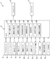
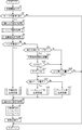
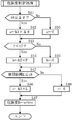
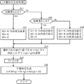
- FIG. 1 is a schematic configuration diagram of a vehicle equipped with a vehicle sound effect generating device according to a first embodiment. It is a block diagram of the sound effect generator for vehicles. It is a vibration sound map. It is a gain map of each adjustment wave sound set corresponding to the lateral acceleration, (a) is a standard gain map, (b) is a decrease gain map, (c) is an increase gain map. It is a flowchart of a sound effect generation process. It is a flowchart of a horizontal input amount setting process. It is a flowchart of a map selection process. It is a flowchart of a risk determination process. It is a flowchart of a dissonance generation process. It is a flowchart of a harmonic sound generation process. It is a flowchart of a rumble sound generation process. It is a flowchart of a weight setting process.
- the sound effect generator 1 selectively generates engine sound effects (harmonic sound, rumble sound, dissonance sound) according to the running state of the vehicle V, and uses the pitch of the engine sound effect according to the running state.
- engine sound effects harmonic sound, rumble sound, dissonance sound
- the driving information provided to the driver (occupant) through the hearing is provided for the present and the future, and the auditory performance effect during driving is enhanced.
- the sound effect directing function by the sound effect generating device 1 includes a realistic sensation enhancement function, an alerting function, and an operation discomfort cancellation function.
- the harmonic sound is a sound effect obtained by synthesizing a fundamental wave composed of a fundamental frequency component and an integer order adjusted wave composed of an integer order frequency component of the fundamental sound
- a rumble sound is derived from a fundamental frequency component.
- the dissonance is the fundamental sound composed of the fundamental frequency component and the integer order frequency component of the fundamental sound
- It is a sound effect obtained by synthesizing a dissonance adjustment wave sound composed of dissonance frequency components other than the half-order frequency component.
- the primary frequency component is used as the fundamental frequency component
- the primary component wave sound including the primary frequency component is used as the fundamental wave sound.
- the sound effect generator 1 includes an ECU (Electric Control Unit) 2, a pair of left and right speakers 3 and 4 that constitute a part of the audio system, an accelerator sensor 5, and a yaw rate.
- Sensor 6 rudder angle sensor 7, lateral acceleration sensor (hereinafter abbreviated as lateral G sensor) 8, wheel speed sensor 9, gradient sensor 10, weight sensor 11, navigation device 12, turning control device ( (Hereinafter abbreviated as DSC device) 13, driving support device 14, mode switch 15 and the like.
- lateral G sensor lateral acceleration sensor
- DSC device turning control device
- driving support device 14 mode switch 15 and the like.
- the pair of speakers 3 and 4 are connected so as to be able to receive an electrical signal from the ECU 2.
- the sensors 5 to 11 and the mode selector switch 15 are connected to be able to transmit an electrical signal to the ECU 2.
- the devices 12 to 14 are connected to each other.
- the ECU 2 is connected to be able to transmit and receive electrical signals.
- At least one of the sensors 5 to 11 and the devices 12 to 14 corresponds to a traveling state detection unit that detects the traveling state of the vehicle V including the traveling environment information of the vehicle V directly or indirectly. Yes.
- the pair of speakers 3 and 4 are respectively disposed at the lower end portions of the pair of left and right front pillars so as to correspond to the left front position and the right front position of the driver seated in the front seat, respectively.
- These speakers 3 and 4 are configured such that each frequency gain and sound pressure level of the generated sound (sound effect) can be independently changed by an operation signal input from the ECU 2.
- the driver's line of sight is guided in the direction of the speaker 3, and The left front view including the left door mirror can be recognized.
- the driver's line of sight is guided toward the speaker 4 and the driver The right front view including the door mirror can be recognized.
- the accelerator sensor 5 detects the amount of depression of an accelerator pedal (not shown) and outputs a detection signal, and the yaw rate sensor 6 outputs a signal corresponding to the yaw rate y of the vehicle V.
- the steering angle sensor 7 outputs a signal related to the steering angle ⁇ of the steering wheel by the driver, and the lateral G sensor 8 outputs a signal related to the current lateral acceleration A acting on the vehicle V.
- the wheel speed sensor 9 outputs a signal corresponding to the rotational speed of a wheel (not shown) in order to detect the vehicle speed v, and the gradient sensor 10 is a travel lane (road surface) on which the vehicle V is currently traveling or stopped. A signal corresponding to the tilt angle is output.
- the weight sensor 11 outputs a signal related to the weight of a load or the like loaded in the trunk of the vehicle V.
- the navigation device 12 is disposed in the upper center of the instrument panel, and includes a position detector for the vehicle V, a map data input device, a sound output speaker, a monitor, and the like. (Both not shown).
- the navigation device 12 is electrically connected to a GPS receiver (not shown) for detecting the current traveling position of the vehicle V.
- This GPS receiving unit detects the current position of the vehicle V by receiving signals from a plurality of GPS satellites.
- the navigation device 12 includes a map database that stores road map data, a traffic rule database that stores traffic rule data (both not shown), and the like.
- the navigation device 12 provides a route guidance to the driver to the destination using the current position data of the vehicle V, the road map data of the map database, and the traffic rule data of the traffic rule database by the GPS receiver.
- the navigation device 12 outputs the current position data of the vehicle V, road map data, and traffic rule data to the ECU 2.
- the navigation device 12 corresponds to a turning information acquisition unit for acquiring curvature information including the existence position of the curve and the turning radius of the curve in the traveling lane ahead of the traveling direction of the vehicle V from the map database.
- the DSC device 13 receives the input signal from each sensor and executes DSC control in order to improve the running stability when the vehicle V is turning.
- the DSC device 13 determines that the turning posture of the vehicle V has collapsed by a predetermined amount or more based on detection signals from the yaw rate sensor 6, the lateral G sensor 8, and the wheel speed sensor 9,
- the braking force of each wheel is controlled by the operation of a pressurizing unit (not shown), and the yaw moment is applied to the vehicle body to converge the turning posture of the vehicle V in the target direction.
- the DSC device 13 receives an input signal from each sensor and performs ABS control to prevent wheel lock of each wheel.
- the DSC device 13 calculates the slip ratio of each wheel based on the detection signal of the wheel speed sensor 9, and controls the pressure unit when the calculated slip ratio detects a wheel that exceeds a predetermined threshold. Thus, the braking force acting on the corresponding wheel is reduced to prevent wheel lock.
- the DSC device 13 calculates a road surface friction coefficient ⁇ (hereinafter simply referred to as a friction coefficient ⁇ ) based on the detection signal of the lateral G sensor 8 and the detection signal of the wheel speed sensor 9 in addition to the slip ratio of each wheel.
- the friction coefficient ⁇ is output to the ECU 2.
- the driving support device 14 has an inter-vehicle distance notification function in front of and behind the vehicle V, a driver emotion improvement function, and the like.
- the inter-vehicle distance notification function means that when another vehicle (preceding vehicle or succeeding vehicle) or an obstacle is present in a region separated by a predetermined distance in front and rear of the vehicle V during traveling, the speakers 3 and 4 are used. This is a function to make the driver recognize the danger of a collision by turning on an alarm or a warning lamp (not shown) and to avoid the collision by guiding the driver to perform an avoidance operation.
- Emotion improvement function is based on the driver's facial expressions and movements, estimating the driver's emotions related to emotions while driving, and lighting or music to improve the driver's emotions from the uncomfortable or inactive state. It is a function that induces to an active state.
- the driving support device 14 includes CCD (Charge Coupled Device) cameras 16 to 18 capable of capturing still images or moving images.
- CCD Charge Coupled Device
- the front camera 16 is mounted in the vicinity of a rearview mirror (not shown) on the lower surface on the front end side of the roof panel, and the white line position of the traveling lane ahead in the traveling direction, the preceding vehicle, and the curve ahead in the traveling direction enter through the front window glass.
- -It is configured to be able to image the escape position.
- the rear camera 17 is attached to the lower surface of the rear end side of the roof panel, and is configured to be able to image a subsequent vehicle or the like through a rear window glass.
- These cameras 16 and 17 are stereo type cameras in which the lens mechanism and shutter mechanism of two cameras are combined into one unit, and the distance from the object to be imaged and the direction from the vehicle V to the object to be imaged are individually determined. It is configured to be detectable.
- the indoor camera 18 is mounted, for example, on the upper part of the instrument panel, and images the upper body including the driver's face.
- the captured upper body image is a facial image cut out to specify facial expressions
- eye iris (iris) is enlarged to detect pupil dimensions and line-of-sight direction, the center of gravity position of the image and the shape of the driver's upper body Based on this, it is used to specify the posture.
- a biaxial plane for example, Russell's emotional ring model
- a feature such as a driver's facial expression captured by the indoor camera 18
- the driver's feelings are estimated.
- the indoor camera 18 can capture an indoor image including passengers (passengers) other than the driver at a wide angle, and detects the number of passengers on the vehicle V based on the captured image.
- the mode changeover switch 15 is configured by a momentary changeover switch that can select the start (operation start) of the sound effect generator 1 and the type (mode) of the sound effect.
- the mode changeover switch 15 generates a sound effect of the engine mainly composed of the harmonic sound by a predetermined on operation, and a second mode generates a sound effect of the engine mainly composed of the rumble sound by the predetermined on operation. And can be switched.
- a harmonic sound that combines the fundamental sound and one or more integer-order adjusted sound Is a stretch and forms a consonant that gives the driver a pleasant impression.
- the half-order adjusted sound consisting of the half-order frequency components whose even-order overtones are harmonic series of the fundamental wave sounds, although there is some interference with the fundamental wave sound, but because the driver (occupant) is slightly sensation
- the rumble sound obtained by synthesizing the fundamental wave sound and one or more half-order adjusted wave sounds is powerful and forms a quasi-consonant sound that allows a driver or the like to perceive a sense of power.
- the risk B determined by the risk determination unit 25 described later is the risk determination threshold.
- the third mode for generating the engine sound effect mainly of the dissonance is configured to be executed.
- the sound effect generated in the third mode includes a fundamental wave sound composed of a fundamental frequency component, and one or a plurality of dissonance adjustment wave sounds composed of a dissonance frequency component other than the integer order frequency component and the half order frequency component of the fundamental sound. Therefore, it is a dissonant sound that gives rise to an unpleasant impression accompanied by a sense of tension or vigilance for the driver.
- ECU2 is comprised so that a driver
- the ECU 2 is formed by a CPU (Central Processing Unit), a ROM, a RAM, an amplifier, an in-side interface, an out-side interface, and the like.
- a CPU Central Processing Unit
- ROM Read Only Memory
- RAM Random Access Memory
- amplifier an in-side interface
- out-side interface and the like.
- the ROM stores various programs and data for generating engine sound effects, and the RAM is provided with a processing area used when the CPU performs a series of processes.
- the in-side interface is electrically connected to the sensors 5 to 11, the devices 12 to 14 and the mode changeover switch 15, and the out-side interface is connected to the pair of speakers 3 and 4 and the devices 12 to 14 via an amplifier. And are electrically connected.
- the ECU 2 stores a vibration sound map M1 (vibration sound database) that stores a plurality of sound sources set in advance so as to match the sound generated from the four-cylinder gasoline engine mounted on the vehicle V.
- M1 vibration sound database
- the vibration sound map M1 is a unit from the primary component wave sound of the fundamental frequency component (fundamental sound) to the 10th component wave sound having a frequency component 10 times the fundamental frequency component for each engine speed.
- a sound source for each frequency (for example, 0.01th order frequency) is stored.
- the fundamental wave sound the integer order component sound (integer order adjusted wave sound) having a frequency component that is an integral multiple of the fundamental frequency component, and the even order overtones of the fundamental wave sound are included for each engine speed.
- the ECU 2 includes a lateral input amount setting unit 21, an adjustment wave sound selection unit 22, a behavior delay prediction unit 23, an inhibition state determination unit 24, a risk determination unit 25, and a lateral G calculation unit.
- 26 lateral acceleration calculation unit
- a sound effect generation unit 27 a line-of-sight guidance direction setting unit 28, and the like.
- the lateral input amount setting unit 21 detects the movement of the vehicle V in the vehicle width direction based on the traveling state of the vehicle V detected by the traveling state detection unit (at least one of the sensors 5 to 11 and the devices 12 to 14).
- a lateral input amount P having a physical quantity related to at least one of the movements in the turning direction as a parameter can be set.
- the lateral input amount P is calculated by the following equation (1).
- the lateral input amount setting unit 21 sets the lateral input amount P to the lateral acceleration A when the vehicle speed v of the vehicle V is less than the determination threshold value t2.
- the vehicle speed v is low, such as when turning left or right at an intersection, the vehicle V is unlikely to slip or slip, so the lateral acceleration A that most reflects the actual turning state of the vehicle V is used as the lateral input amount P.
- the lateral input amount P only needs to reflect at least the vehicle state in the lateral direction, and is any one of the steering angle ⁇ , the yaw rate y, and the lateral acceleration A of the steering wheel as in the lateral input amount P at the low vehicle speed.
- One detection value may be used as the lateral input amount P regardless of the vehicle speed v, and a parameter combining two or more detection values may be adopted as the lateral input amount P regardless of the vehicle speed v. is there.
- the adjustment wave sound selection unit 22 is configured to be able to select one or a plurality of adjustment wave sounds to be synthesized from the plurality of component wave sounds stored in the vibration sound map M1 to the fundamental wave sound N0.
- the adjustment wave sound selection unit 22 selects the first to third adjustment wave sounds N1 to N3, and uses the gain maps M2 to M4 selected based on the running state, respectively, for the first to third adjustment wave sounds N1 to N3.
- First to third gains g1 to g3 (0 ⁇ g1 ⁇ g2 ⁇ g3) to be corrected are determined.
- the ECU 2 stores a standard gain map M2, a decrease gain map M3, and an increase gain map M4 in advance.
- the gains ⁇ 2 to ⁇ 4, ⁇ 2 to ⁇ 4, and ⁇ 2 to ⁇ 4 of the first to third adjustment wave sounds N1 to N3, which is one of the output characteristics of the sound effects, are defined to be zero when the lateral acceleration A is zero.
- the gain value is set symmetrically so that the gain value increases in a linear function as the absolute value of the lateral acceleration A increases.
- the gains ⁇ 2 to ⁇ 4, ⁇ 2 to ⁇ 4, and ⁇ 2 to ⁇ 4 have gain values that increase at a rate larger than the previous rate from a predetermined middle point, and converge to a constant value at the upper limit value.
- gain values are respectively defined so that the following expression (2) is established.
- gain values are respectively defined so that the following expression (3) is established.
- the selection of the gain maps M2 to M4 by the adjustment wave sound selection unit 22 is performed using the prediction result of the behavior delay prediction unit 23 and the determination result of the inhibition state determination unit 24 as determination conditions.
- the behavior delay prediction unit 23 generates a behavior delay of the vehicle V when the total weight of the vehicle V specified from the number of passengers and the weight of the load (hereinafter simply referred to as vehicle weight) is equal to or greater than the determination threshold value t3. Configured to predict.
- the adjustment wave sound selection unit 22 selects the increase gain map M4 having high responsiveness.
- the behavior of the vehicle V is likely to be delayed with respect to the steering angle operation (operation amount) by the driver.
- An increase gain map M4 having high responsiveness is selected to increase and correct the sound effect prior to the behavior. As a result, the behavioral delay of the vehicle V can be corrected audibly to eliminate the driver's uncomfortable feeling.
- the inhibition state determination unit 24 is in a situation where the correspondence between the operation amount by the driver and the behavior of the vehicle V is inhibited.
- the vehicle V is configured to be determined to be in a situation where the operability of the vehicle V is lowered (hereinafter referred to as an inhibition situation).
- the adjustment wave sound selection unit 22 selects the decrease gain map M3 having low responsiveness.
- the adjustment wave sound selection unit 22 selects the decrease gain map M3 having low responsiveness in order to decrease and correct the effect sound. As a result, it is possible to eliminate the driver's uncomfortable feeling by aurally correcting the follow-up deterioration of the vehicle V.
- the standard gain map M2 whose response is a standard value is selected.
- the adjustment wave sound selection unit 22 is configured to select the first to third adjustment wave sounds N1 to N3 composed of integer frequency components based on the lateral input amount P.
- the second-order component sound that is the integer-order frequency component closest to the fundamental frequency component is assigned to the first adjustment wave sound N1.
- the lateral input amount P is larger than the determination threshold p2 and equal to or less than the determination threshold p3 (p2 ⁇ p3), in addition to the already selected first adjustment wave sound N1, an integer next to the secondary component wave sound
- the third-order component sound that is the second-order frequency component is assigned to the second adjustment sound N2
- the lateral input amount P is larger than the determination threshold value p3, in addition to the already selected first and second adjustment sound N1, N2,
- a fourth-order component sound which is an integer-order frequency component adjacent to the third-order component sound, is assigned to the third adjustment wave sound N3.
- the adjustment wave sound selection unit 22 obtains the gain g1 ( ⁇ 2 to ⁇ 4) for correcting the first adjustment wave sound N1 based on the lateral input amount P from any of the selected gain maps M2 to M4, and the second adjustment wave sound N2.
- a gain g2 ( ⁇ 2 to ⁇ 4) to be corrected and a gain g3 ( ⁇ 2 to ⁇ 4) to correct the third adjustment wave sound N3 are extracted.
- the adjustment wave sound selection unit 22 increases the number of the first to third adjustment wave sounds N1 to N3 as the lateral input amount P is larger, and the selected first to third adjustment wave sounds.
- the first to third gains g1 to g3 of the third adjustment wave sounds N1 to N3 are increased, respectively.
- the adjustment wave sound selection unit 22 is configured to select the first to third adjustment wave sounds N1 to N3 composed of the half-order frequency components based on the lateral input amount P.
- the 1.5th order component sound that is the half-order frequency component closest to the fundamental frequency component is assigned to the first adjustment wave sound N1
- the lateral input amount P Is greater than the determination threshold p2 and equal to or less than the determination threshold p3 in addition to the already selected first adjustment wave sound N1 it is a half-order frequency component next to the 1.5th-order component sound 2.5.
- the second component wave sound is assigned to the second adjustment wave sound N2 and the lateral input amount P is larger than the determination threshold value p3, in addition to the already selected first and second adjustment wave sounds N1 and N2, the 2.5th component wave sound
- the third-order component sound which is the next-order half-order frequency component, is assigned to the third adjustment sound N3.
- the adjustment wave sound composed of the half-order frequency component can increase the cooperative level (quasi-cooperative level) as it approaches the fundamental frequency component.
- the adjustment wave sound selection unit 22 has a gain g1 for correcting the first adjustment wave sound N1 based on the lateral input amount P from any of the selected gain maps M2 to M4, and a second A gain g2 for correcting the adjustment wave sound N2 and a gain g3 for correcting the third adjustment wave sound N3 are extracted.
- the adjustment wave sound selection unit 22 increases the number of the first to third adjustment wave sounds N1 to N3 as the lateral input amount P increases, and selects each of the first to third selection wave sounds.
- the first to third gains g1 to g3 of the third adjustment wave sounds N1 to N3 are increased, respectively.
- the adjustment wave sound selection unit 22 selects the first to third adjustment wave sounds N1 to N3 made of the dissonance frequency components based on the risk B. It is configured.
- the risk determination unit 25 determines the risk B of the vehicle V based on the current running state.
- the risk determination unit 25 determines each determination amount a to c based on the steering angular velocity ⁇ by the steering operation of the driver, the lateral input amount P, and the inter-vehicle distance L between the preceding vehicle and the nearest vehicle among the following vehicles.
- the risk level B is calculated based on these determination amounts a to c.
- the rudder angular velocity determination amount a is calculated by the following equation (4) when the rudder angular velocity ⁇ is equal to or greater than the determination threshold t6, and is zero otherwise. Note that k1 to k3 (0 ⁇ k1, k2, k3) are correction coefficients.
- the lateral input amount determination amount b is calculated by the following equation (5) when the lateral input amount P is equal to or less than the determination threshold value t7, and is zero otherwise.
- the inter-vehicle distance determination amount c is calculated by the following equation (6) when the inter-vehicle distance L is equal to or less than the determination threshold t8, and is zero otherwise.
- the risk level B is calculated by the following equation (7).
- the risk B is accurately determined not only when the determination amount is high on average but also when the determination amount is high only for a specific determination amount.
- the adjustment wave sound selection unit 22 has a risk B determined by the risk determination unit 25 equal to or higher than a determination threshold r1 (0 ⁇ r1) in a state where any one of the first and second modes is selected. At this time, it is determined that the third mode is selected, and the first to third adjustment wave sounds N1 to N3 are selected based on the degree of risk B.
- the integer frequency component (10th frequency component) and the half frequency component (9.5th order) are farthest from the fundamental frequency component.
- the 9.75th order component wave sound which is a dissonant frequency component located in the middle of the frequency component
- the risk B is greater than the determination threshold value r2
- the determination threshold value r3 is assigned to the first adjustment wave sound N1
- the frequency components are separated from the fundamental frequency component next to the 9.75th order component sound, and the integer order frequency component (9th order frequency component) and the half order frequency component ( 9.
- the 9.25th order component wave sound which is a dissonance frequency component located in the middle of the 9.5th order frequency component
- the risk B is greater than the determination threshold value r3, it is already selected.
- 1st and 2nd adjustment wave In addition to N1 and N2, it is separated from the fundamental frequency component next to the 9.25th order component wave sound, and intermediate between the integer order frequency component (9th order frequency component) and the half order frequency component (8.5th order frequency component).
- the 8.75th order component wave sound which is a dissonant frequency component, is allocated to the third adjustment wave sound N3.
- the reason for this is that the adjustment wave sound composed of the dissonant frequency components increases (amplifies) the interference as the distance from the fundamental frequency component increases, and the distance from the integer frequency component and the half frequency component increases. This is because the level of cooperation can be increased.
- the adjustment wave sound selection unit 22 has a gain g1 for correcting the first adjustment wave sound N1 based on the lateral input amount P from any of the selected gain maps M2 to M4.
- the gain g2 for correcting the second adjustment wave sound N2 and the gain g3 for correcting the third adjustment wave sound N3 are extracted to correct the first to third adjustment wave sounds N1 to N3.
- the adjustment wave sound selection unit 22 increases the number of the first to third adjustment wave sounds N1 to N3 that are selected as the degree of risk B increases, and each selected first sound.
- the first to third gains g1 to g3 of the first to third adjustment wave sounds N1 to N3 are increased, respectively.
- the adjustment wave sound selection unit 22 selects the first to third adjustment wave sounds N1 to N3 when the predicted lateral acceleration A1 calculated by the lateral G calculation unit 25 is equal to or greater than the determination threshold t1, and is selected based on the running state.
- the first to third gains g1 to g3 for correcting the first to third adjustment wave sounds N1 to N3 are determined using the gain maps M2 to M4.
- the lateral G calculation unit 26 determines whether or not a curve exists ahead of the traveling direction of the vehicle V based on the map information including the turning radius input from the map database of the navigation device 12. Is configured to calculate the predicted lateral acceleration A1 acting on the vehicle V when turning around the curve.
- the calculation of the predicted lateral acceleration A1 is that a curve exists in a preset distance from the current position where the vehicle V is traveling, or in a region where the vehicle V is predicted to reach within a preset time. It is executed as a condition.
- the wheel turning angle ⁇ t can be calculated by the following equation (8), where ⁇ p is the predicted steering angle of the vehicle V corresponding to the turning radius of the curve, and gr is the gear ratio of the vehicle V.
- the front wheel position rotation radius R of the vehicle V can be calculated by the following equation (9), where W is the wheel base of the vehicle V.
- the predicted lateral acceleration A1 can be expressed by the following equation (10) when the vehicle speed is v, the near future will be obtained by substituting the front wheel position rotation radius R calculated by the equation (9) into the equation (10).
- the predicted lateral acceleration A1 that acts on the vehicle V when the vehicle is turning can be obtained.
- the sound effect generator 27 corrects the first to third adjustment wave sounds N1 to N3 with the first to third gains g1 to g3 extracted for each mode, respectively, and generates the fundamental sound.
- the sound effect S is generated by synthesizing N0 and the first to third adjustment wave sounds N1 to N3 corrected after selection.
- the sound effect generating unit 27 increases the sound pressure level of the sound effect S as the lateral input amount P is larger, as the danger level B is larger, and as the predicted lateral acceleration A1 is larger.
- the driver is made to recognize the degree of the lateral input amount P, the degree of risk B, and the predicted lateral acceleration A1 that affect the traveling of the vehicle V.
- Effect sound generator 27 the sound pressure level correction coefficient for a pair of speakers 3, 4 G L, set the G R, and is capable of changing the sound pressure level of the sound effect each independently.
- the sound effect generator 27 increases the sound pressure level of the line-of-sight guidance direction side speaker 3 (4) set by the line-of-sight guidance direction setting unit 28, and the sound of the speaker 4 (3) on the opposite side with respect to the line-of-sight guidance direction ⁇ d.
- the sound pressure level is decreasing.
- the correction coefficients k4 and k5 are obtained as interpolation coefficients that are set based on the line-of-sight guidance direction ⁇ d.
- the line-of-sight guidance direction setting unit 28 determines the presence / absence of a line-of-sight guidance request based on various information from the navigation device 12, the driving support apparatus 14, and the like.
- the line-of-sight guidance direction ⁇ d to be directed is configured to be settable.
- An object to which the driver should turn his / her line of sight is an object that may affect the traveling of the vehicle V in terms of safety or maneuverability when the driver does not visually recognize the line of sight.
- it is defined as a direction in which the driver can visually recognize an object to which the line of sight should be directed.
- the vehicle V passes the right side of the vehicle V, and therefore when the vehicle V changes the lane to the right lane, There is a risk of vehicles contacting each other. Therefore, when the driving support device 14 detects a sudden approach by the following vehicle (or a vehicle traveling in the right lane), the line-of-sight guidance direction setting unit 28 determines that there is a line-of-sight guidance request and displays the driver's line of sight on the right door mirror. Therefore, the line-of-sight guidance direction ⁇ d corresponding to the right front is set, and the sound image from the speakers 3 and 4 is localized in this line-of-sight guidance direction ⁇ d.
- the driving assistance device 14 detects a curve escape position during traveling
- the visual guidance direction setting unit 28 determines that there is a visual guidance request, and the visual guidance direction ⁇ d corresponding to the escape position of the curve. And the sound image by the speakers 3 and 4 is localized in the line-of-sight guidance direction ⁇ d.
- the line-of-sight guidance direction setting unit 28 determines that there is a line-of-sight guidance request and based on the map information of the navigation device 12.
- the line-of-sight guidance direction ⁇ d corresponding to the parking area (or overhead sign) position is set, and the sound images from the speakers 3 and 4 are localized in this line-of-sight guidance direction ⁇ d.
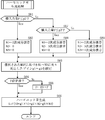
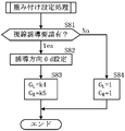
- the sound effect generation process first, in S1, various information such as detection values and determination threshold values of the sensors are read and the first to third adjustments set in the previous routine are performed.
- the wave sounds N1 to N3, the gains g1 to g3, the sound pressure level correction coefficient F, the sound pressure level correction coefficients G L and G R , and the determination amounts a to c are initialized, and the process proceeds to S2.
- the process proceeds to S3 and a lateral input amount setting process is performed. If the result of the determination in S2 is that the mode switch 15 has not been turned on, the process returns without executing the sound effect generation process.
- the 9.75th order component sound that is a dissonance frequency component is set to the first adjustment wave sound N1, and the second and third adjustment wave sounds N2 and N3 are not set (in this case, N2 and N3 are set to zero). The same applies hereinafter), and the process proceeds to S53.
- the gain g1 (g2, g3) for the adjusted wave sound N1 (N2, N3) set in the previous step is set based on the gain map selected in the map selection process.
- the sound pressure level correction coefficient is a value obtained by adding the first adjustment wave sound N1 corrected by the gain g1, the second adjustment wave sound N2 corrected by the gain g2, and the third adjustment wave sound N3 corrected by the gain g3.
- the 9.75th order component sound is set to the first adjusted sound N1
- the 9.25th order sound that is a dissonance frequency component is set to the second adjusted sound N2
- the third adjusted sound N3 is set.
- the 9.75th order component sound is set to the first adjusted sound N1
- the 9.25th order sound is set to the second adjusted sound N2
- the 8.75th order component sound which is a dissonance frequency component, is set to the third.
- the secondary component wave sound that is an integer frequency component is set to the first adjustment wave sound N1, and the process proceeds to S63 without setting the second and third adjustment wave sounds N2 and N3.
- the gain g1 (g2, g3) for the adjusted wave sound N1 (N2, N3) set in the previous step is set based on the gain map selected in the map selection process.
- the sound pressure level correction coefficient is a value obtained by adding the first adjustment wave sound N1 corrected by the gain g1, the second adjustment wave sound N2 corrected by the gain g2, and the third adjustment wave sound N3 corrected by the gain g3. After the multiplication value multiplied by F is set to the sound effect S, the process is terminated.
- the secondary component wave sound is set to the first adjustment wave sound N1
- the third-order component wave sound that is an integer frequency component is set to the second adjustment wave sound N2
- the third adjustment wave sound N3 is not set to S63. Transition.
- the second-order component sound is set to the first adjustment sound N1
- the third-order sound is set to the second adjustment sound N2
- the fourth-order sound that is an integer frequency component is set to the third adjustment sound N3. Then, the process proceeds to S63.
- the 1.5th-order component sound that is a half-order frequency component is set to the first adjustment wave sound N1, and the process proceeds to S73 without setting the second and third adjustment wave sounds N2 and N3.
- the gain g1 (g2, g3) for the adjusted wave sound N1 (N2, N3) set in the previous step is set based on the gain map selected in the map selection process.
- the sound pressure level correction coefficient is a value obtained by adding the first adjustment wave sound N1 corrected by the gain g1, the second adjustment wave sound N2 corrected by the gain g2, and the third adjustment wave sound N3 corrected by the gain g3.
- the 1.5th order component wave sound is set to the first adjustment wave sound N1
- the 2.5th order component wave sound that is the half order frequency component is set to the second adjustment wave sound N2
- the third adjustment wave sound N3 is set.
- the 1.5th order component wave sound is set to the first adjustment wave sound N1
- the 2.5th order component wave sound is set to the second adjustment wave sound N2
- the 3.5th order component wave sound that is the half order frequency component is set to the third.
- the risk determination unit 25 that can determine the risk B of the vehicle V based on the travel state detected by the sensors 6 to 8 and the driving support device 14 (travel state detection unit). Since it is provided, it is possible to determine the risk level B reflecting the actual vehicle behavior.
- the risk level B is determined by the risk level determination unit 25 to be equal to or higher than the determination threshold r1
- the first to third adjustment wave sounds N1 to N3 composed of the inharmonic frequency components other than the integer frequency component and the half frequency component. Since the sound effect generating unit 27 for synthesizing the sound and the fundamental wave sound N0 is provided, it is possible to enhance the occupant's sense of tension and alertness by generating a dissonance that matches the actual vehicle behavior.
- the sound effect generating device 1 selects the first to third adjustment wave sounds N1 to N3 composed of the dissonance frequency components other than the integer order frequency component and the half order frequency component based on the risk B, and outputs them to the sound effect generation unit 27 Since the adjustment wave sound selection unit 22 increases the number of first to third adjustment wave sounds N1 to N3 to be synthesized with the fundamental wave sound N0 as the degree of risk B increases, the adjustment wave sound selection part 22 increases the number of dissonance levels. The number of auditory performances can be increased while maintaining.
- the sound effect generator 27 increases the sound pressure level of the sound effect S (S L , S R ) as the risk level B increases, so that the occupant perceives a sense of tension and alertness according to the risk level B. can do.
- the adjustment wave sound selection unit 22 is most distant from the fundamental frequency component among the plurality of dissonance adjustment wave sounds included in the vibration sound map M1, and is located in the middle of the integer order frequency component and the half order frequency component N1. Therefore, the interference with the fundamental wave sound N0 can be increased, and a dissonance with a sense of discomfort can be generated.
- the adjustment wave sound selection unit 22 increases the gains g1 to g3 of the dissonance adjustment wave sound as the dissonance frequency component is separated from the fundamental frequency component. It is possible to emphasize the sense of tension and alertness perceived by.
- the adjustment wave sound selection unit 22 is configured to be able to select the first to third adjustment wave sounds N1 to N3 composed of integer order frequency components, or the first to third adjustment wave sounds N1 to N3 composed of half order frequency components.
- the generating unit 27 is configured to be able to synthesize the fundamental wave sound N0 and the first to third adjustment wave sounds N1 to N3 made up of an integer order adjustment sound or a half order adjustment wave sound, and the risk B is greater than or equal to the determination threshold value r1.
- the first to third adjustment wave sounds N1 to N3 have priority over any of the second modes in which the half-order adjustment wave sounds are selected as N1 to N3 and the half-order adjustment sound and the fundamental wave sound N0 are synthesized. Select the adjustment wave sound and select the dissonance adjustment wave sound and the fundamental wave. And N0 performing a third mode of synthesis.
- the number of adjustment wave sounds synthesized with the fundamental wave sound can be set up to three based on the running state.
- the number of adjustment wave sounds may be set to 2 or 4 or more.
- the sound effect generating unit changes the localization direction of the sound image by changing the sound pressure level of the pair of left and right speakers
- the sound pressure level of the pair of speakers is changed.
- the sound image localization direction may be changed by providing a delay time for the sound effect reaching the driver without changing the sound pressure level of the pair of speakers.
- the localization direction of the sound image can be moved to the line-of-sight guidance direction side by delaying the output from the speaker on the side opposite to the line-of-sight guidance direction from the output from the speaker on the line-of-sight guidance direction.
- the localization direction of the sound image may be linearly displaced from the front direction of the driver toward the line-of-sight guidance direction, or this displacement operation may be repeated.
- the speakers may be movable, and the line-of-sight guidance direction can be set in a three-dimensional manner by increasing the number of speakers arranged above the pair of speakers in addition to the pair of speakers.
- the detection means may be a means other than the CCD, such as a millimeter wave radar.
- the sound effect generator for generating the engine sound effect based on the lateral input amount has been described. However, it is sufficient to generate the engine dissonance sound effect based on at least the degree of risk. Also, it may be used in combination with a sound effect generator that generates engine sound effects based on the accelerator opening.
- the engine sound effect is generated based on the accelerator opening, one or a plurality of integer-order or half-order adjusted wave sounds and gains of those adjusted wave sounds are set based on the accelerator opening, and the larger the accelerator opening is, the larger the accelerator opening is.
- the number of adjustment wave sounds to be synthesized with the fundamental wave sound, the gain value for correcting these adjustment wave sounds, and the sound pressure level of the sound effect are controlled to increase.
- the vibration sound map is prepared for each engine specification, for example, the displacement and the number of cylinders, and the mounted engine is changed. In this case, it may be configured to be switchable to the vibration sound map according to the engine specifications.
- the vibration sound map of the 4-cylinder gasoline engine actually mounted on the vehicle has been described, the vibration sound map of an arbitrary internal combustion engine (for example, a 4-cylinder gasoline engine) with respect to a hybrid vehicle or an electric vehicle. Sound effects using may be generated.
- an arbitrary internal combustion engine for example, a 4-cylinder gasoline engine
- the embodiment relates to a vehicle sound effect generating device that generates engine sound effects based on a vibration sound database including a fundamental wave sound composed of a fundamental frequency component and a plurality of adjustment sound waves composed of frequency components other than the fundamental frequency component.
- the vehicle sound effect generating device includes a travel state detection unit that detects a travel state of the vehicle, a risk determination unit that can determine the risk level of the vehicle based on the travel state detected by the travel state detection unit, When the risk level determination unit determines a risk level equal to or higher than a predetermined value, the fundamental frequency sound is synthesized with one or a plurality of dissonance adjustment wave sounds including non-coincident frequency components other than integer frequency components and half-order frequency components. And a sound effect generator.
- a travel state detection unit that detects the travel state of the vehicle
- a risk determination unit that can determine the risk level of the vehicle based on the travel state detected by the travel state detection unit. Since it is provided, it is possible to determine the degree of risk reflecting the actual vehicle behavior.
- the risk level determination unit determines a risk level equal to or higher than a predetermined value
- one or a plurality of non-coincidence adjustment wave sounds including non-coincident frequency components other than an integer frequency component and a half-order frequency component and the fundamental sound Since the sound effect generating unit for synthesizing the sound is provided, it is possible to enhance the occupant's sense of tension and alertness by generating a dissonance that matches the actual vehicle behavior.
- the sound effect generating device for a vehicle selects one or a plurality of dissonance adjustment wave sounds composed of dissonance frequency components other than an integer order frequency component and a half order frequency component based on the risk, and the sound effect generation unit
- the adjustment wave sound selection unit further outputs the adjustment wave sound, and the adjustment wave sound selection unit increases the number of dissonance adjustment wave sounds to be synthesized with the fundamental wave sound as the degree of risk increases.
- This configuration can increase the number of auditory performances while maintaining the dissonance level.
- the sound effect generator increases the sound pressure level of the sound effect as the degree of danger increases.
- the adjustment wave sound selection unit is the most distant from the fundamental frequency component among a plurality of dissonance adjustment wave sounds included in the vibration sound database, and is located between the integer-order frequency component and the half-order frequency component. Select to include Kyowa adjustment sound.
- the adjustment wave sound selection unit increases the gain of the dissonance adjustment wave sound as the dissonance frequency component is separated from the fundamental frequency component when selecting a plurality of dissonance adjustment wave sounds.
- the adjustment wave sound selection unit is configured to be able to select one or a plurality of integer order adjustment wave sounds composed of integer order frequency components, or one or a plurality of half order adjustment wave sounds composed of half order frequency components, and the sound effect
- the generating unit is configured to be able to synthesize the fundamental wave sound and the integer-order adjusted wave sound or the half-order adjusted wave sound, and when the degree of risk is determined to be equal to or greater than the predetermined value,
- a first mode for synthesizing the fundamental wave sound and the dissonance-adjusted wave sound has priority over both the first mode for synthesizing the adjustment wave sound and the second mode for synthesizing the fundamental wave sound and the half-order adjustment wave sound. 3 mode is executed.
Landscapes
- Physics & Mathematics (AREA)
- Engineering & Computer Science (AREA)
- Acoustics & Sound (AREA)
- Health & Medical Sciences (AREA)
- Signal Processing (AREA)
- Audiology, Speech & Language Pathology (AREA)
- General Health & Medical Sciences (AREA)
- Multimedia (AREA)
- Otolaryngology (AREA)
- Fittings On The Vehicle Exterior For Carrying Loads, And Devices For Holding Or Mounting Articles (AREA)
- Circuit For Audible Band Transducer (AREA)
Abstract
Description
γ3<β3<α3
γ4<β4<α4 ‥‥(2)
β3<β2<β4
γ3<γ2<γ4 ‥‥(3)
N2←g2×N2
N3←g3×N3 ‥‥(11)
前記実施形態をまとめると以下のとおりである。
Claims (6)
- 基本周波数成分からなる基本波音と基本周波数成分以外の周波数成分からなる複数の調整波音を含む振動音データベースに基づいてエンジンの効果音を生成する車両用効果音発生装置において、
車両の走行状態を検出する走行状態検出部と、
前記走行状態検出部により検出された走行状態に基づいて車両の危険度を判定可能な危険度判定部と、
前記危険度判定部により所定値以上の危険度が判定されたとき、整数次周波数成分及び半次周波数成分以外の不協和周波数成分からなる1又は複数の不協和調整波音と前記基本波音とを合成する効果音生成部とを備えたことを特徴とする車両用効果音発生装置。 - 前記危険度に基づき整数次周波数成分及び半次周波数成分以外の不協和周波数成分からなる1又は複数の不協和調整波音を選択して前記効果音生成部に出力する調整波音選択部をさらに備え、
前記調整波音選択部は、前記危険度が大きい程前記基本波音と合成する不協和調整波音の数を増加することを特徴とする請求項1に記載の車両用効果音発生装置。 - 前記効果音生成部は、前記危険度が大きい程前記効果音の音圧レベルを増加することを特徴とする請求項1又は2に記載の車両用効果音発生装置。
- 前記調整波音選択部は、前記振動音データベースに含まれる複数の不協和調整波音のうち前記基本周波数成分から最も離隔すると共に整数次周波数成分と半次周波数成分との中間に位置する不協和調整波音を含むように選択することを特徴とする請求項2又は3に記載の車両用効果音発生装置。
- 前記調整波音選択部は、複数の不協和調整波音を選択するとき、前記基本周波数成分から離隔した不協和周波数成分である程不協和調整波音のゲインを増加することを特徴とする請求項2~4の何れか1項に記載の車両用効果音発生装置。
- 前記調整波音選択部は、整数次周波数成分からなる1又は複数の整数次調整波音、又は半次周波数成分からなる1又は複数の半次調整波音を選択可能に構成され、
前記効果音生成部は、前記基本波音と前記整数次調整波音又は半次調整波音を合成可能に構成されると共に、前記危険度が前記所定値以上と判定された場合には、前記基本波音と前記整数次調整波音とを合成する第1モードと、前記基本波音と前記半次調整波音とを合成する第2モードとのいずれよりも優先して、前記基本波音と前記不協和調整波音とを合成する第3モードを実行することを特徴とする請求項2~5の何れか1項に記載の車両用効果音発生装置。
Priority Applications (3)
| Application Number | Priority Date | Filing Date | Title |
|---|---|---|---|
| EP17774311.9A EP3419017A4 (en) | 2016-03-31 | 2017-03-15 | Sound effect generation device for vehicles |
| US15/762,401 US10290297B2 (en) | 2016-03-31 | 2017-03-15 | Sound effect generation device for vehicles |
| CN201780018824.3A CN108885867B (zh) | 2016-03-31 | 2017-03-15 | 车用效果声发生装置 |
Applications Claiming Priority (2)
| Application Number | Priority Date | Filing Date | Title |
|---|---|---|---|
| JP2016071384A JP6281590B2 (ja) | 2016-03-31 | 2016-03-31 | 車両用効果音発生装置 |
| JP2016-071384 | 2016-03-31 |
Publications (1)
| Publication Number | Publication Date |
|---|---|
| WO2017169767A1 true WO2017169767A1 (ja) | 2017-10-05 |
Family
ID=59964302
Family Applications (1)
| Application Number | Title | Priority Date | Filing Date |
|---|---|---|---|
| PCT/JP2017/010343 Ceased WO2017169767A1 (ja) | 2016-03-31 | 2017-03-15 | 車両用効果音発生装置 |
Country Status (5)
| Country | Link |
|---|---|
| US (1) | US10290297B2 (ja) |
| EP (1) | EP3419017A4 (ja) |
| JP (1) | JP6281590B2 (ja) |
| CN (1) | CN108885867B (ja) |
| WO (1) | WO2017169767A1 (ja) |
Families Citing this family (7)
| Publication number | Priority date | Publication date | Assignee | Title |
|---|---|---|---|---|
| CN110891825B (zh) * | 2017-08-09 | 2023-04-07 | 三菱自动车工业株式会社 | 车辆警报装置 |
| JP7122405B2 (ja) * | 2021-01-22 | 2022-08-19 | 本田技研工業株式会社 | 能動型効果音発生装置 |
| KR20230090051A (ko) * | 2021-12-14 | 2023-06-21 | 현대자동차주식회사 | 차량 사운드 제어 장치 및 방법 |
| US20230254556A1 (en) * | 2022-02-04 | 2023-08-10 | Zimeno, Inc. Dba Monarch Tractor | Sensor maintenance |
| JP2025078191A (ja) * | 2023-11-08 | 2025-05-20 | トヨタ自動車株式会社 | 車両管理システム及び電気自動車 |
| JP2025078195A (ja) * | 2023-11-08 | 2025-05-20 | トヨタ自動車株式会社 | 車両管理システム及び電気自動車 |
| CN119922456B (zh) * | 2025-04-03 | 2025-11-11 | 深圳市天际通电气有限公司 | 一种车载音效调整控制系统 |
Citations (4)
| Publication number | Priority date | Publication date | Assignee | Title |
|---|---|---|---|---|
| JPH1178689A (ja) * | 1997-09-10 | 1999-03-23 | Fuji Heavy Ind Ltd | 車両用警報装置 |
| JP2004074994A (ja) * | 2002-08-21 | 2004-03-11 | Mazda Motor Corp | 車室内音制御装置 |
| JP2004078036A (ja) * | 2002-08-21 | 2004-03-11 | Mazda Motor Corp | 車室内音制御装置 |
| JP2010175854A (ja) * | 2009-01-29 | 2010-08-12 | Pioneer Electronic Corp | エンジン音出力装置、出力制御方法、出力制御プログラムおよび記録媒体 |
Family Cites Families (19)
| Publication number | Priority date | Publication date | Assignee | Title |
|---|---|---|---|---|
| US6768944B2 (en) * | 2002-04-09 | 2004-07-27 | Intelligent Technologies International, Inc. | Method and system for controlling a vehicle |
| JPH10269495A (ja) * | 1997-03-26 | 1998-10-09 | Mitsubishi Motors Corp | 車両の走行補助装置 |
| JP4101220B2 (ja) * | 2003-09-18 | 2008-06-18 | 力 大橋 | 環境設定装置 |
| JP2006096070A (ja) * | 2004-09-28 | 2006-04-13 | Yamaha Corp | 車載用音源システム |
| JP4725236B2 (ja) * | 2005-08-16 | 2011-07-13 | ヤマハ株式会社 | 車外警告音報知装置 |
| JP4539608B2 (ja) * | 2006-05-18 | 2010-09-08 | ヤマハ株式会社 | 運転支援装置 |
| JP2008025492A (ja) | 2006-07-21 | 2008-02-07 | Toyota Central Res & Dev Lab Inc | 車両制御装置 |
| JP4384681B2 (ja) * | 2007-07-25 | 2009-12-16 | 本田技研工業株式会社 | 能動型効果音発生装置 |
| JP5040541B2 (ja) * | 2007-09-10 | 2012-10-03 | ヤマハ株式会社 | エンジン音合成装置 |
| JP5067329B2 (ja) * | 2008-09-23 | 2012-11-07 | 株式会社デンソー | 車載用スピーカ吹鳴装置の駆動方法 |
| US8270621B2 (en) * | 2009-02-11 | 2012-09-18 | International Business Machines Corporation | Automatic generation of audible alert according to ambient sound |
| JP5445773B2 (ja) * | 2010-03-30 | 2014-03-19 | マツダ株式会社 | 車両用発音装置 |
| JP2011255847A (ja) * | 2010-06-11 | 2011-12-22 | Mitsubishi Motors Corp | 車両の接近報知装置 |
| US9299337B2 (en) | 2011-01-11 | 2016-03-29 | Bose Corporation | Vehicle engine sound enhancement |
| JP5692142B2 (ja) * | 2012-04-06 | 2015-04-01 | トヨタ自動車株式会社 | 模擬音発生装置、模擬音発生方法、プログラム及び媒体 |
| US20140056438A1 (en) * | 2012-08-21 | 2014-02-27 | Harman International Industries, Incorporated | System for vehicle sound synthesis |
| FR3013884B1 (fr) * | 2013-11-28 | 2015-11-27 | Peugeot Citroen Automobiles Sa | Dispositif de generation d'un signal sonore representatif de la dynamique d'un vehicule et induisant une illusion auditive |
| EP2884489B1 (en) * | 2013-12-16 | 2020-02-05 | Harman Becker Automotive Systems GmbH | Sound system including an engine sound synthesizer |
| CN204688340U (zh) * | 2015-05-29 | 2015-10-07 | 南京信息工程大学 | 一种谐波电动助力运动车 |
-
2016
- 2016-03-31 JP JP2016071384A patent/JP6281590B2/ja not_active Expired - Fee Related
-
2017
- 2017-03-15 EP EP17774311.9A patent/EP3419017A4/en not_active Withdrawn
- 2017-03-15 CN CN201780018824.3A patent/CN108885867B/zh active Active
- 2017-03-15 WO PCT/JP2017/010343 patent/WO2017169767A1/ja not_active Ceased
- 2017-03-15 US US15/762,401 patent/US10290297B2/en not_active Expired - Fee Related
Patent Citations (4)
| Publication number | Priority date | Publication date | Assignee | Title |
|---|---|---|---|---|
| JPH1178689A (ja) * | 1997-09-10 | 1999-03-23 | Fuji Heavy Ind Ltd | 車両用警報装置 |
| JP2004074994A (ja) * | 2002-08-21 | 2004-03-11 | Mazda Motor Corp | 車室内音制御装置 |
| JP2004078036A (ja) * | 2002-08-21 | 2004-03-11 | Mazda Motor Corp | 車室内音制御装置 |
| JP2010175854A (ja) * | 2009-01-29 | 2010-08-12 | Pioneer Electronic Corp | エンジン音出力装置、出力制御方法、出力制御プログラムおよび記録媒体 |
Non-Patent Citations (1)
| Title |
|---|
| See also references of EP3419017A4 * |
Also Published As
| Publication number | Publication date |
|---|---|
| JP6281590B2 (ja) | 2018-02-21 |
| CN108885867B (zh) | 2023-01-31 |
| JP2017181918A (ja) | 2017-10-05 |
| CN108885867A (zh) | 2018-11-23 |
| EP3419017A1 (en) | 2018-12-26 |
| EP3419017A4 (en) | 2018-12-26 |
| US10290297B2 (en) | 2019-05-14 |
| US20180268805A1 (en) | 2018-09-20 |
Similar Documents
| Publication | Publication Date | Title |
|---|---|---|
| JP6465058B2 (ja) | 車両用効果音発生装置 | |
| JP6465057B2 (ja) | 車両用効果音発生装置 | |
| JP6281590B2 (ja) | 車両用効果音発生装置 | |
| CN109074801B (zh) | 车用效果声发生装置 | |
| JP6465059B2 (ja) | 車両用効果音発生装置 | |
| JP6311737B2 (ja) | 車両用効果音発生装置 | |
| KR20220159646A (ko) | 진동 발생 장치 및 그를 가지는 차량 | |
| JP6347418B2 (ja) | 車両用効果音発生装置 | |
| JP2019098862A (ja) | 車両制御装置 | |
| JP7550738B2 (ja) | 運転支援装置、運転支援方法、およびプログラム | |
| KR20260051718A (ko) | 가상엔진음 출력 제어 장치 및 방법 | |
| CN112513956A (zh) | 包括用于将音频信号输出到机动车辆的乘员室中的装置的机动车辆 |
Legal Events
| Date | Code | Title | Description |
|---|---|---|---|
| WWE | Wipo information: entry into national phase |
Ref document number: 15762401 Country of ref document: US |
|
| WWE | Wipo information: entry into national phase |
Ref document number: 2017774311 Country of ref document: EP |
|
| ENP | Entry into the national phase |
Ref document number: 2017774311 Country of ref document: EP Effective date: 20180920 |
|
| NENP | Non-entry into the national phase |
Ref country code: DE |
|
| 121 | Ep: the epo has been informed by wipo that ep was designated in this application |
Ref document number: 17774311 Country of ref document: EP Kind code of ref document: A1 |