WO2017169784A1 - 低温乾燥装置 - Google Patents
低温乾燥装置 Download PDFInfo
- Publication number
- WO2017169784A1 WO2017169784A1 PCT/JP2017/010404 JP2017010404W WO2017169784A1 WO 2017169784 A1 WO2017169784 A1 WO 2017169784A1 JP 2017010404 W JP2017010404 W JP 2017010404W WO 2017169784 A1 WO2017169784 A1 WO 2017169784A1
- Authority
- WO
- WIPO (PCT)
- Prior art keywords
- furnace body
- infrared
- low
- temperature
- dried
- Prior art date
- Legal status (The legal status is an assumption and is not a legal conclusion. Google has not performed a legal analysis and makes no representation as to the accuracy of the status listed.)
- Ceased
Links
Images

Classifications
-
- F—MECHANICAL ENGINEERING; LIGHTING; HEATING; WEAPONS; BLASTING
- F26—DRYING
- F26B—DRYING SOLID MATERIALS OR OBJECTS BY REMOVING LIQUID THEREFROM
- F26B3/00—Drying solid materials or objects by processes involving the application of heat
- F26B3/28—Drying solid materials or objects by processes involving the application of heat by radiation, e.g. from the sun
- F26B3/30—Drying solid materials or objects by processes involving the application of heat by radiation, e.g. from the sun from infrared-emitting elements
-
- F—MECHANICAL ENGINEERING; LIGHTING; HEATING; WEAPONS; BLASTING
- F26—DRYING
- F26B—DRYING SOLID MATERIALS OR OBJECTS BY REMOVING LIQUID THEREFROM
- F26B13/00—Machines and apparatus for drying fabrics, fibres, yarns, or other materials in long lengths, with progressive movement
-
- F—MECHANICAL ENGINEERING; LIGHTING; HEATING; WEAPONS; BLASTING
- F26—DRYING
- F26B—DRYING SOLID MATERIALS OR OBJECTS BY REMOVING LIQUID THEREFROM
- F26B15/00—Machines or apparatus for drying objects with progressive movement; Machines or apparatus with progressive movement for drying batches of material in compact form
- F26B15/10—Machines or apparatus for drying objects with progressive movement; Machines or apparatus with progressive movement for drying batches of material in compact form with movement in a path composed of one or more straight lines, e.g. compound, the movement being in alternate horizontal and vertical directions
- F26B15/12—Machines or apparatus for drying objects with progressive movement; Machines or apparatus with progressive movement for drying batches of material in compact form with movement in a path composed of one or more straight lines, e.g. compound, the movement being in alternate horizontal and vertical directions the lines being all horizontal or slightly inclined
- F26B15/122—Machines or apparatus for drying objects with progressive movement; Machines or apparatus with progressive movement for drying batches of material in compact form with movement in a path composed of one or more straight lines, e.g. compound, the movement being in alternate horizontal and vertical directions the lines being all horizontal or slightly inclined the objects or batches of material being carried by transversely moving rollers or rods which may rotate
-
- F—MECHANICAL ENGINEERING; LIGHTING; HEATING; WEAPONS; BLASTING
- F26—DRYING
- F26B—DRYING SOLID MATERIALS OR OBJECTS BY REMOVING LIQUID THEREFROM
- F26B21/00—Arrangements for supplying or controlling air or other gases for drying solid materials or objects
- F26B21/50—Ducting arrangements from the source of air or other gases to the materials or objects being dried
-
- F—MECHANICAL ENGINEERING; LIGHTING; HEATING; WEAPONS; BLASTING
- F26—DRYING
- F26B—DRYING SOLID MATERIALS OR OBJECTS BY REMOVING LIQUID THEREFROM
- F26B23/00—Heating arrangements
- F26B23/04—Heating arrangements using electric heating
Definitions
- the present invention relates to a low temperature drying apparatus.
- a drying device a furnace body, a moving body that moves in the interior space of the furnace body with an object to be dried, an infrared heater disposed above the interior space of the furnace body,
- a device provided with a gas supply means for supplying a gas whose temperature and humidity are adjusted to an internal space see Patent Document 1.
- this type of drying apparatus includes an infrared transmission plate that partitions a first space including a moving body and a second space including an infrared heater in the internal space of the furnace body, and the temperature and humidity are adjusted in the first space.
- Patent Document 2 There is also known one that allows the gas to pass through.
- any drying apparatus since an infrared heater is disposed in the interior space of the furnace body, a wavelength unnecessary for drying an object to be dried is absorbed by the furnace wall, the temperature of the furnace wall rises, Atmospheric temperature sometimes increased. Depending on the object to be dried, the allowable upper limit temperature may be low. In such a case, the furnace atmosphere temperature may exceed the upper limit temperature.
- the present invention has been made to solve such problems, and is intended to efficiently dry without exceeding the upper limit temperature even when drying an object to be dried whose allowable upper limit temperature is low. Objective.
- the low-temperature drying apparatus of the present invention is A furnace body; An object to be dried holding member for holding the object to be dried so that the object to be dried is disposed inside the furnace body; An infrared transmitting plate provided on a surface of the furnace body facing the object to be dried holding member; Cooling air circulation means for circulating cooling air between the object to be dried and the infrared transmission plate held by the object to be dried holding member; An infrared heater arranged to face the infrared transmitting plate in an open space outside the furnace body; It is equipped with.
- the furnace wall since there is no furnace wall around the infrared heater, the furnace wall does not absorb a wavelength unnecessary for drying an object to be dried and does not reach a high temperature. Therefore, it is possible to prevent the furnace atmosphere temperature from being excessively increased. Further, since cooling air flows between the object to be dried and the infrared transmission plate, the object to be dried and its holding member can be maintained at a relatively low temperature, and the infrared transmission plate can also be maintained at a low temperature. . From the above, even when an object to be dried having a low allowable upper limit temperature is dried, it can be efficiently dried without exceeding the upper limit temperature.
- the low-temperature drying apparatus of the present invention may include a temperature-lowering means for lowering the temperature around the infrared heater. Although the periphery of the infrared heater is heated by the infrared heater, the temperature is lowered by the temperature lowering means. Although the gas around the infrared heater is in contact with the infrared transmission plate, the temperature of the gas is lowered, so that the infrared transmission plate can be reliably maintained at a low temperature.
- the cooling air circulation means has an air supply port and an exhaust port for the cooling air, and the air supply port and the exhaust port are elongated along the plate surface of the infrared transmission plate. You may form in the slit which extends. If it carries out like this, since cooling air will flow easily along the plate
- At least a side surface of the furnace body may be a metal surface that does not have a heat insulating material. In this way, even if the furnace atmosphere temperature rises, heat is easily dissipated through the metal surface that does not have a heat insulating material, so that the furnace atmosphere temperature can be kept low.
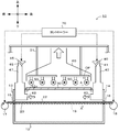
- FIG. 1 is a longitudinal sectional view showing a schematic configuration of a low-temperature drying apparatus 10.
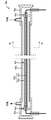
- FIG. 2 is a cross-sectional view taken along line AA in FIG. 1. The longitudinal cross-sectional view of the infrared heater 50.
- FIG. 1 is a longitudinal sectional view showing a schematic configuration of a low temperature drying apparatus 10 according to an embodiment of the present invention
- FIG. 2 is a sectional view taken along line AA in FIG.
- the front-rear direction and the up-down direction of the low-temperature drying device 10 are as shown in FIG. 1, and the left-right direction of the low-temperature drying device 10 is a direction perpendicular to the paper surface (the back of the paper surface is left and the front is right).
- the low-temperature drying device 10 includes a furnace body 12, a sheet 20, an infrared transmission plate 30, an air supply device 40, an exhaust device 45, an infrared heater 50, a heater duct 60, and a controller 70. .
- the low-temperature drying device 10 includes a roll 17 provided in front of the furnace body 12 and a roll 18 provided in the rear of the furnace body 12.
- This low-temperature drying apparatus 10 is configured as a roll-to-roll type drying apparatus that continuously transports and drys the sheet 20 having the coating film 22 formed on the upper surface thereof by rolls 17 and 18.
- the furnace body 12 is for drying the coating film.
- the furnace body 12 is a structure formed in a substantially rectangular parallelepiped, and the front surface 13, the rear surface 14, and the left and right side surfaces (not shown) are metal surfaces having no heat insulating material.
- the metal surface should just have high heat conductivity, for example, stainless steel, anodized aluminum, etc. are mentioned. This metal surface may be provided with columns and beams for providing structural strength.
- An infrared transmission plate 30 is fitted on the upper surface of the furnace body 12 at a position facing the sheet 20. Openings 15 and 16 are provided in the front surface 13 and the rear surface 14 of the furnace body 12, respectively. The openings 15 and 16 serve as entrances and exits into the furnace body 12.
- the furnace body 12 has a length from the front surface 13 to the rear surface 14 of, for example, 2 to 10 m.
- the furnace body 12 includes a transfer passage 19 extending from the opening 15 to the opening 16.
- the conveyance passage 19 penetrates the furnace body 12 in the horizontal direction.
- the sheet 20 on which the coating film 22 is applied on one side passes through the conveyance path 19.
- the sheet 20 is not particularly limited, but is, for example, a resin sheet.
- the sheet 20 is made of a PET film.
- the sheet 20 is not particularly limited.
- the thickness is 10 to 100 ⁇ m
- the width (length in the left-right direction) is 200 to 1000 mm
- the length of the sheet 20 in the furnace in the front-rear direction is 1000 to 1500 mm.
- the coating film 22 is applied to the upper surface of the sheet 20, and is used as a thin film for MLCC (multilayer ceramic capacitor) after drying, for example.
- the coating film 22 contains, for example, ceramic powder or metal powder, an organic binder, and an organic solvent.
- the thickness of the coating film 22 is not particularly limited, but is, for example, 20 to 1000 ⁇ m.
- the infrared transmitting plate 30 is attached so as to cover the opening 12a provided on the upper surface of the furnace body 12, and is opposed to the sheet 20 on which the coating film 22 is held.
- the infrared transmitting plate 30 is made of quartz glass, borosilicate crown glass, or the like, and functions as a filter that passes infrared rays having a wavelength of 3.5 ⁇ m or less and absorbs infrared rays having a wavelength exceeding 3.5 ⁇ m.
- the infrared transmitting plate 30 is preferably made of the same material as an inner tube 53 and an outer tube 55 of the infrared heater 50 described later.
- the infrared transmission plate is not limited to the one that transmits infrared rays having a wavelength of 3.5 ⁇ m or less, and may be one that transmits infrared rays having a long wavelength such as 6 ⁇ m.
- the air supply device 40 is a device that supplies (blows) fluid to the surface side of the sheet 20 to cool the coating film 22, the sheet 20, and the infrared transmission plate 30 that pass through the furnace body 12.
- the air supply device 40 includes an air supply fan 41, a pipe structure 42, and an air supply port 43.
- the air supply fan 41 is attached to the pipe structure 42 and supplies fluid to the inside of the pipe structure 42.
- the fluid is cool air that can cool the sheet 20, for example, air at normal temperature or 50 ° C. or less.
- the air supply fan 41 can adjust the flow rate and temperature of the fluid.
- the pipe structure 42 serves as a fluid passage from the air supply fan 41.
- the pipe structure 42 forms a passage from the air supply fan 41 through the ceiling of the furnace body 12 to the inside of the furnace body 12.
- the air supply port 43 serves as a supply port for supplying fluid from the air supply fan 41 to the furnace body 12.
- the air supply port 43 is provided on the opening 16 side that is the carry-out side of the sheet 20 in the furnace body 12, and opens toward the opening 15 side that is the carry-in side. As shown in FIG. 2, the air supply port 43 is formed in a slit that extends in the longitudinal direction along the plate surface of the infrared transmission plate.
- the air supply device 40 supplies fluid in the direction opposite to the conveyance direction of the sheet 20 (in the left direction in FIG. 1).
- the exhaust device 45 is a device that discharges the atmospheric gas in the furnace body 12.
- the exhaust device 45 includes an exhaust fan 46, a pipe structure 47, and an exhaust port 48.
- the exhaust port 48 is provided on the opening 15 side which is the carry-in side of the sheet 20 in the furnace body 12 and opens toward the opening 16 side which is the carry-out side.
- the exhaust port 48 is also formed in a slit that is elongated in the front-rear direction along the plate surface of the infrared transmission plate.
- the exhaust port 48 is attached to the pipe structure 47, and sucks atmospheric gas in the furnace body 12 (mainly air blown from the air supply device 40 after flowing along the surface of the coating film 22) to form the pipe structure. Guide into the body 47.
- the pipe structure 47 serves as a flow path for the atmospheric gas from the exhaust port 48 to the exhaust fan 46.
- the pipe structure 47 forms a passage from the exhaust port 48 through the ceiling of the furnace body 12 to the exhaust fan 46.
- the exhaust fan 46 is attached to the pipe structure 47 and exhausts the atmospheric gas inside the pipe structure 47.
- the infrared heater 50 is a device that irradiates the coating film 22 passing through the furnace body 12 from the outside of the furnace body 12 through the infrared transmission plate 30, and is provided in an open space OP outside the furnace body 12. A plurality of pieces are suspended from the frame 51. These infrared heaters 50 are opposed to the infrared transmission plate 30.
- the open space OP is a space in the building where the furnace body 12 is installed.
- a plurality of infrared heaters 50 (six in this embodiment) are arranged substantially evenly from the front part to the rear part of the infrared transmission plate 30.
- the plurality of infrared heaters 50 have the same configuration, and are attached so that the longitudinal direction thereof is orthogonal to the conveying direction of the coating film 22.
- the configuration of one infrared heater 50 will be described with reference to FIGS. 3 and 4.
- 3 is a longitudinal sectional view of the infrared heater 50
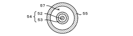
- FIG. 4 is a sectional view taken along the line BB of FIG.
- the infrared heater 50 is airtightly fitted to a heater body 54 formed so that the inner tube 53 surrounds the heating element 52, an outer tube 55 formed so as to surround the heater body 54, and both ends of the outer tube 55.
- the heating element 52 is energized and heated to 700 to 1200 ° C., and emits infrared rays having a peak at a wavelength near 3 ⁇ m.
- the inner tube 53 is made of quartz glass, borosilicate crown glass, or the like, and functions as a filter that passes infrared rays having a wavelength of 3.5 ⁇ m or less and absorbs infrared rays having a wavelength exceeding 3.5 ⁇ m.
- the heater body 54 is supported at both ends by holders 58 disposed inside the cap 56.
- the outer tube 55 is made of quartz glass, borosilicate crown glass, or the like, and passes through infrared rays having a wavelength of 3.5 ⁇ m or less and absorbs infrared rays having a wavelength exceeding 3.5 ⁇ m. Function.
- the refrigerant flows from a supply port provided in one cap 56 to a discharge port provided in the other cap 56.
- the refrigerant flowing through the flow path 57 is, for example, air or an inert gas, and cools the tubes 53 and 55 by contacting the inner tube 53 and the outer tube 55 to remove heat.
- infrared heater 50 when infrared rays having a peak near 3 ⁇ m are emitted from the heating element 52, infrared rays having a wavelength of 3.5 ⁇ m or less pass through the inner tube 53 and the outer tube 55 to be heated. Irradiated.
- Infrared light having this wavelength is said to be excellent in the ability to break the hydrogen bond of the organic solvent, and can efficiently evaporate the organic solvent.
- the inner tube 53 and the outer tube 55 absorb infrared rays having a wavelength exceeding 3.5 ⁇ m, but are cooled by the refrigerant flowing through the flow path 57. Therefore, the outer surface of the infrared heater 50 can be maintained at 200 ° C. or lower.
- the heater duct 60 is for exhausting and ventilating the gas around the infrared heater 50 disposed in the open space OP outside the furnace body 12 to the outside of the building where the low-temperature drying device 10 is installed. . For this reason, the temperature around the infrared heater 50 can be kept low.
- the controller 70 is configured as a microprocessor centered on a CPU.
- the controller 70 outputs a control signal to the air supply fan 41 and the exhaust fan 46 to control the temperature and the air volume of the fluid blown from the air supply port 43 and the exhaust amount from the exhaust port 48. To do.
- the controller 70 can adjust the passage time of the sheet 20 and the coating film 22 in the furnace body 12 and the tension applied to the sheet 20 and the coating film 22 by controlling the rotation speed of the rolls 17 and 18. .
- the controller 70 also performs output control of each infrared heater 50.
- the controller 70 rotates the rolls 17 and 18 and starts conveying the sheet 20. As a result, the sheet 20 is unwound from the roll 17 disposed at the left end of the low-temperature drying apparatus 10.
- a coating film 22 is applied to the upper surface by a coater (not shown). And the sheet
- the controller 70 controls the air supply fan 41, the exhaust fan 46, the infrared heater 50, and the like.
- the coating film 22 formed on the upper surface of the sheet 20 is dried by being irradiated with infrared rays from the infrared heater 50 through the infrared transmission plate 30.
- the coating film 22, the sheet 20, and the infrared transmission plate 30 are cooled by the cold air from the air supply device 40, and the solvent evaporated from the coating film 22 is discharged from the exhaust device 45.
- the heater duct 60 exhausts the warm air around the infrared heater 50 and ventilates it.
- the coating film 22 is dried to a thin film while being kept at a low furnace atmosphere temperature (for example, 40 ° C.
- the low-temperature drying apparatus 10 of the present embodiment corresponds to the low-temperature drying apparatus of the present invention
- the furnace body 12 corresponds to the furnace body
- the sheet 20 corresponds to the object to be dried holding member
- the infrared transmission plate 30 serves as the infrared transmission plate.
- the air supply device 40 and the exhaust device 45 correspond to cooling air circulation means
- the infrared heater 50 corresponds to an infrared heater
- the heater duct 60 corresponds to a low temperature means.
- the furnace wall since the furnace wall does not exist around the infrared heater 50, the furnace wall absorbs a wavelength unnecessary for drying the coating film 22, and the temperature is increased. None become. Therefore, it is possible to prevent the atmospheric temperature inside the furnace body 12 from rising excessively. Moreover, since the cooling air flows between the coating film 22 and the infrared transmission plate 30, the coating film 22 and the sheet 20 can be maintained at a relatively low temperature, and the infrared transmission plate 30 can also be maintained at a low temperature. it can. From the above, even when the coating film 22 having a low allowable upper limit temperature is dried, it can be efficiently dried without exceeding the upper limit temperature.
- the infrared heater 50 is disposed outside the furnace, the furnace volume can be reduced. Furthermore, even if the temperature of the infrared heater 50 becomes high, the inside of the furnace is hardly affected, so that the output of the infrared heater 50 can be increased and drying can be performed in a short time.
- the surroundings of the infrared heater 50 are heated by the infrared heater 50, they are ventilated by the heater duct 60 and replaced with a new gas having a low temperature.
- the gas around the infrared heater 50 is in contact with the infrared transmitting plate 30, the temperature of the gas is lowered, so that the infrared transmitting plate 30 can be reliably maintained at a low temperature.
- the cooling air supply port 43 and the exhaust port 48 are formed as slits extending along the plate surface of the infrared transmission plate 30, the cooling air easily flows along the plate surface of the infrared transmission plate 30.
- the plate surface of the infrared transmission plate 30 can be efficiently cooled.
- the side surface of the furnace body 12 is a metal surface that does not have a heat insulating material, heat is easily radiated through the metal surface that does not have a heat insulating material even if the temperature inside the furnace increases. Therefore, the furnace atmosphere temperature can be kept low.
- the roll-to-roll system in which the sheet 20 is bridged between the two rolls 17 and 18 is exemplified, but the present invention is not particularly limited thereto.
- the heater duct 60 is provided in the open space OP, but an air conditioner for controlling the temperature and humidity of the open space OP may be attached instead of the heater duct 60. Even in this way, the temperature of the gas around the infrared heater 50 can be lowered.
- the infrared heater 50 that emits infrared light having a wavelength of 3.5 ⁇ m or less is employed.
- the infrared heater 50 is not particularly limited to this, and an appropriate wavelength region in the range of 0.7 to 1000 ⁇ m is adopted. You can use what you have.
- the coating film 22 is used as a thin film for MLCC, but is not limited thereto.
- it may be used as a thin film for LTCC (low temperature fired ceramics) or other green sheets.
- the coating film 22 is good also as what is used as a coating film used as an electrode for batteries, such as a lithium ion secondary battery.
- the coating film 22 may be formed by applying an electrode material paste obtained by kneading together an electrode material (positive electrode active material or negative electrode active material), a binder, a conductive material, and a solvent onto the sheet 20.
- the coating film 22 is a coating film that serves as an electrode for a battery
- the sheet 20 may be a metal sheet such as aluminum or copper.
- the positional relationship of the air supply port 43 of the air supply device 40 is not particularly specified, but in order to prevent convective heat from rising from the coating film 22 due to the processing or heating of the coating film 22. If the upper portion 43a (see FIG. 2) of the air supply port 43 is located closer to the infrared transmission plate 30 than the middle point (the middle point) between the coating film 22 and the infrared transmission plate 30, the present The effect of the invention is easily achieved.
- the present invention can be used in industries that require drying of an object to be dried such as a coating film, for example, a ceramic industry that manufactures MLCC, LTCC, and the like, a battery industry that manufactures an electrode coating film of a lithium ion secondary battery, and the like.
- a coating film for example, a ceramic industry that manufactures MLCC, LTCC, and the like, a battery industry that manufactures an electrode coating film of a lithium ion secondary battery, and the like.
Landscapes
- Engineering & Computer Science (AREA)
- Mechanical Engineering (AREA)
- General Engineering & Computer Science (AREA)
- Life Sciences & Earth Sciences (AREA)
- Chemical & Material Sciences (AREA)
- Combustion & Propulsion (AREA)
- Microbiology (AREA)
- Sustainable Development (AREA)
- Textile Engineering (AREA)
- Drying Of Solid Materials (AREA)
Abstract
Description
炉体と、
被乾燥物が前記炉体の内部に配置されるように前記被乾燥物を保持する被乾燥物保持部材と、
前記炉体のうち前記被乾燥物保持部材と対向する面に設けられた赤外線透過板と、
前記被乾燥物保持部材に保持される前記被乾燥物と前記赤外線透過板との間に冷却風を流通させる冷却風流通手段と、
前記炉体の外側の開放空間において前記赤外線透過板と対向するように配置された赤外線ヒーターと、
を備えたものである。
Claims (4)
- 炉体と、
被乾燥物が前記炉体の内部に配置されるように前記被乾燥物を保持する被乾燥物保持部材と、
前記炉体のうち前記被乾燥物保持部材と対向する面に設けられた赤外線透過板と、
前記被乾燥物保持部材に保持される前記被乾燥物と前記赤外線透過板との間に冷却風を流通させる冷却風流通手段と、
前記炉体の外側の開放空間において前記赤外線透過板と対向するように配置された赤外線ヒーターと、
を備えた低温乾燥装置。 - 請求項1に記載の低温乾燥装置であって、
前記赤外線ヒーターの周囲を低温にする低温化手段
を備えた低温乾燥装置。 - 前記冷却風流通手段は、前記冷却風の供給口及び排出口を有し、
前記供給口及び前記排出口は、前記赤外線透過板の板面に沿って細長く延びるスリットである、
請求項1又は2に記載の低温乾燥装置。 - 前記炉体の少なくとも側面は、断熱材を有さない金属面である、
請求項1~3のいずれか1項に記載の低温乾燥装置。
Priority Applications (5)
| Application Number | Priority Date | Filing Date | Title |
|---|---|---|---|
| JP2017545970A JP6368436B2 (ja) | 2016-03-28 | 2017-03-15 | 低温乾燥装置 |
| CN201780020350.6A CN108885056A (zh) | 2016-03-28 | 2017-03-15 | 低温干燥装置 |
| KR1020187027891A KR102383920B1 (ko) | 2016-03-28 | 2017-03-15 | 저온 건조 장치 |
| EP17774328.3A EP3438588B1 (en) | 2016-03-28 | 2017-03-15 | Low-temperature drying apparatus |
| US16/141,040 US10739069B2 (en) | 2016-03-28 | 2018-09-25 | Low-temperature drying apparatus |
Applications Claiming Priority (2)
| Application Number | Priority Date | Filing Date | Title |
|---|---|---|---|
| JP2016063626 | 2016-03-28 | ||
| JP2016-063626 | 2016-03-28 |
Related Child Applications (1)
| Application Number | Title | Priority Date | Filing Date |
|---|---|---|---|
| US16/141,040 Continuation US10739069B2 (en) | 2016-03-28 | 2018-09-25 | Low-temperature drying apparatus |
Publications (1)
| Publication Number | Publication Date |
|---|---|
| WO2017169784A1 true WO2017169784A1 (ja) | 2017-10-05 |
Family
ID=59965290
Family Applications (1)
| Application Number | Title | Priority Date | Filing Date |
|---|---|---|---|
| PCT/JP2017/010404 Ceased WO2017169784A1 (ja) | 2016-03-28 | 2017-03-15 | 低温乾燥装置 |
Country Status (7)
| Country | Link |
|---|---|
| US (1) | US10739069B2 (ja) |
| EP (1) | EP3438588B1 (ja) |
| JP (1) | JP6368436B2 (ja) |
| KR (1) | KR102383920B1 (ja) |
| CN (1) | CN108885056A (ja) |
| TW (1) | TWI717484B (ja) |
| WO (1) | WO2017169784A1 (ja) |
Cited By (2)
| Publication number | Priority date | Publication date | Assignee | Title |
|---|---|---|---|---|
| US20190024972A1 (en) * | 2016-03-28 | 2019-01-24 | Ngk Insulators, Ltd. | Low-temperature drying apparatus |
| WO2025017784A1 (ja) * | 2023-07-14 | 2025-01-23 | 日本碍子株式会社 | 乾燥炉 |
Families Citing this family (7)
| Publication number | Priority date | Publication date | Assignee | Title |
|---|---|---|---|---|
| KR102266685B1 (ko) * | 2020-02-17 | 2021-06-21 | 엔지케이 인슐레이터 엘티디 | 열처리로 |
| KR102825541B1 (ko) * | 2020-09-21 | 2025-06-27 | 삼성디스플레이 주식회사 | 가스 건조기 및 이를 구비하는 용매 제거장치와 멀티 챔버 시스템 |
| CN116940055A (zh) | 2022-04-08 | 2023-10-24 | 贺利氏特种光源有限公司 | 冷却的红外线或uv模块 |
| CN115930580B (zh) * | 2022-10-25 | 2025-02-07 | 南京华易泰电子科技有限公司 | 一种面板玻璃干燥设备 |
| CN117091386B (zh) * | 2023-08-03 | 2025-12-05 | 连云港海蓝研磨材料有限公司 | 一种具备分批控制的特种陶瓷成型干燥装置 |
| KR102665473B1 (ko) | 2023-12-29 | 2024-05-10 | (주)상엔지니어링건축사사무소 | 방진 및 방음장치가 구비된 공동주택용 바닥재 |
| KR102665457B1 (ko) | 2023-12-29 | 2024-05-10 | (주)상엔지니어링건축사사무소 | 공동주택용 층간소음 저감 장치가 구비된 바닥재 |
Citations (6)
| Publication number | Priority date | Publication date | Assignee | Title |
|---|---|---|---|---|
| JPS55158485A (en) * | 1979-05-28 | 1980-12-09 | Toyota Motor Co Ltd | Vertical furnace |
| JP2013057438A (ja) * | 2011-09-08 | 2013-03-28 | Toppan Printing Co Ltd | 塗膜の乾燥装置 |
| WO2013111511A1 (ja) * | 2012-01-23 | 2013-08-01 | 日本碍子株式会社 | Petフィルムの表面に形成された塗膜の乾燥方法および塗膜乾燥炉 |
| WO2014073289A1 (ja) * | 2012-11-07 | 2014-05-15 | 日本碍子株式会社 | 赤外線加熱装置及び乾燥炉 |
| JP2014181889A (ja) * | 2013-03-21 | 2014-09-29 | Dainippon Printing Co Ltd | 空気流処理装置 |
| JP5721897B1 (ja) * | 2014-11-28 | 2015-05-20 | 日本碍子株式会社 | 赤外線処理装置及び赤外線ヒーター |
Family Cites Families (31)
| Publication number | Priority date | Publication date | Assignee | Title |
|---|---|---|---|---|
| US2419643A (en) * | 1944-10-02 | 1947-04-29 | James W Swenson | Oven structure |
| US2478001A (en) * | 1945-11-30 | 1949-08-02 | William J Miskella | Infrared oven |
| DE7028556U (de) * | 1970-07-29 | 1971-04-08 | Philips Patentverwaltung | Erhitzungsvorrichtung mit infrarotstrahlungseinheiten. |
| US3900959A (en) * | 1973-05-07 | 1975-08-26 | Minnesota Mining & Mfg | Combined infra-red and air flow drying for photographic film |
| US4501072A (en) * | 1983-07-11 | 1985-02-26 | Amjo, Inc. | Dryer and printed material and the like |
| US5155798A (en) * | 1989-02-21 | 1992-10-13 | Glenro, Inc. | Quick-response quartz tube infra-red heater |
| US5319861A (en) * | 1990-11-16 | 1994-06-14 | Setsuo Tate | Drying method and device for coated layer |
| JP3259049B2 (ja) * | 1997-06-06 | 2002-02-18 | 株式会社ヒラノテクシード | 乾燥装置 |
| JP3897456B2 (ja) | 1998-07-15 | 2007-03-22 | 大日本印刷株式会社 | 乾燥装置 |
| US6161304A (en) * | 1999-10-05 | 2000-12-19 | M&R Printing Equipment, Inc. | Dryer assembly |
| ITRM20020452A1 (it) * | 2002-09-10 | 2004-03-11 | Sipa Spa | Procedimento e dispositivo per il trattamento di rivestimenti |
| JP4929747B2 (ja) * | 2005-03-28 | 2012-05-09 | コニカミノルタオプト株式会社 | 光学フィルムの製造方法 |
| US20080193890A1 (en) * | 2007-02-08 | 2008-08-14 | Rogers James H | Textile Curing Oven With Active Cooling |
| US10260811B2 (en) * | 2008-03-05 | 2019-04-16 | Ivoclar Vivadent Ag | Dental furnace |
| JP2010101595A (ja) * | 2008-10-27 | 2010-05-06 | Toray Ind Inc | 乾燥装置および樹脂フィルムの製造方法 |
| CA3172541C (en) * | 2009-06-05 | 2026-04-14 | Durr Systems, Inc. | Improved infrared float bar |
| KR101126769B1 (ko) * | 2009-09-22 | 2012-03-29 | 삼성에스디아이 주식회사 | 다수의 3상 전원 램프를 포함하는 램프 히터 및 이를 이용한 이차 전지 제조용 건조 장치 |
| JP4790092B1 (ja) * | 2010-04-30 | 2011-10-12 | 日本碍子株式会社 | 塗膜乾燥炉 |
| ES2648788T3 (es) * | 2011-01-26 | 2018-01-08 | Inserm - Institut National De La Santé Et De La Recherche Médicale | Método para evaluar el riesgo de un sujeto de tener una enfermedad cardiovascular |
| KR20140115328A (ko) * | 2012-01-23 | 2014-09-30 | 엔지케이 인슐레이터 엘티디 | 건조로 유닛 및 건조로 |
| GB2495161B (en) * | 2012-02-28 | 2013-08-07 | Gew Ec Ltd | Ink curing apparatus |
| US8904668B2 (en) * | 2012-10-11 | 2014-12-09 | Eastman Kodak Company | Applying heating liquid to remove moistening liquid |
| JP6026290B2 (ja) | 2013-01-09 | 2016-11-16 | 東芝メディカルシステムズ株式会社 | X線コンピュータ断層撮影装置 |
| JPWO2014129072A1 (ja) * | 2013-02-20 | 2017-02-02 | 日本碍子株式会社 | ノズル付きヒーター及び乾燥炉 |
| WO2014132952A1 (ja) | 2013-02-26 | 2014-09-04 | 日本碍子株式会社 | 乾燥装置 |
| TW201510451A (zh) * | 2013-04-11 | 2015-03-16 | Ngk Insulators Ltd | 乾燥爐 |
| JP2015036590A (ja) * | 2013-08-12 | 2015-02-23 | 日本碍子株式会社 | 赤外線処理装置及び赤外線処理方法 |
| US9651303B2 (en) * | 2014-04-25 | 2017-05-16 | Bbc Industries, Inc. | Curing oven for printed substratees |
| TWI686100B (zh) | 2014-11-28 | 2020-02-21 | 日商日本碍子股份有限公司 | 紅外線加熱器及紅外線處理裝置 |
| DE102015205338A1 (de) * | 2015-03-24 | 2016-09-29 | Cefla Deutschland Gmbh | Trocknungsvorrichtung |
| CN108885056A (zh) * | 2016-03-28 | 2018-11-23 | 日本碍子株式会社 | 低温干燥装置 |
-
2017
- 2017-03-15 CN CN201780020350.6A patent/CN108885056A/zh active Pending
- 2017-03-15 JP JP2017545970A patent/JP6368436B2/ja active Active
- 2017-03-15 KR KR1020187027891A patent/KR102383920B1/ko active Active
- 2017-03-15 WO PCT/JP2017/010404 patent/WO2017169784A1/ja not_active Ceased
- 2017-03-15 EP EP17774328.3A patent/EP3438588B1/en active Active
- 2017-03-21 TW TW106109289A patent/TWI717484B/zh active
-
2018
- 2018-09-25 US US16/141,040 patent/US10739069B2/en active Active
Patent Citations (6)
| Publication number | Priority date | Publication date | Assignee | Title |
|---|---|---|---|---|
| JPS55158485A (en) * | 1979-05-28 | 1980-12-09 | Toyota Motor Co Ltd | Vertical furnace |
| JP2013057438A (ja) * | 2011-09-08 | 2013-03-28 | Toppan Printing Co Ltd | 塗膜の乾燥装置 |
| WO2013111511A1 (ja) * | 2012-01-23 | 2013-08-01 | 日本碍子株式会社 | Petフィルムの表面に形成された塗膜の乾燥方法および塗膜乾燥炉 |
| WO2014073289A1 (ja) * | 2012-11-07 | 2014-05-15 | 日本碍子株式会社 | 赤外線加熱装置及び乾燥炉 |
| JP2014181889A (ja) * | 2013-03-21 | 2014-09-29 | Dainippon Printing Co Ltd | 空気流処理装置 |
| JP5721897B1 (ja) * | 2014-11-28 | 2015-05-20 | 日本碍子株式会社 | 赤外線処理装置及び赤外線ヒーター |
Non-Patent Citations (1)
| Title |
|---|
| See also references of EP3438588A4 * |
Cited By (3)
| Publication number | Priority date | Publication date | Assignee | Title |
|---|---|---|---|---|
| US20190024972A1 (en) * | 2016-03-28 | 2019-01-24 | Ngk Insulators, Ltd. | Low-temperature drying apparatus |
| US10739069B2 (en) * | 2016-03-28 | 2020-08-11 | Ngk Insulators, Ltd. | Low-temperature drying apparatus |
| WO2025017784A1 (ja) * | 2023-07-14 | 2025-01-23 | 日本碍子株式会社 | 乾燥炉 |
Also Published As
| Publication number | Publication date |
|---|---|
| JP6368436B2 (ja) | 2018-08-01 |
| EP3438588A1 (en) | 2019-02-06 |
| JPWO2017169784A1 (ja) | 2018-04-05 |
| US20190024972A1 (en) | 2019-01-24 |
| KR102383920B1 (ko) | 2022-04-08 |
| EP3438588A4 (en) | 2019-11-20 |
| TWI717484B (zh) | 2021-02-01 |
| TW201809566A (zh) | 2018-03-16 |
| US10739069B2 (en) | 2020-08-11 |
| KR20180127372A (ko) | 2018-11-28 |
| EP3438588B1 (en) | 2021-08-18 |
| CN108885056A (zh) | 2018-11-23 |
Similar Documents
| Publication | Publication Date | Title |
|---|---|---|
| JP6368436B2 (ja) | 低温乾燥装置 | |
| KR101422429B1 (ko) | 건조 장치 및 열처리 시스템 | |
| KR101704946B1 (ko) | 적외선 가열 장치 및 건조로 | |
| KR20150020309A (ko) | 적외선 처리 장치 및 적외선 처리 방법 | |
| JP5775224B2 (ja) | 赤外線加熱ユニット,赤外線加熱装置及び乾燥装置 | |
| WO2014168229A1 (ja) | 乾燥炉 | |
| KR101969044B1 (ko) | 히터 유닛 및 열처리 장치 | |
| WO2013111647A1 (ja) | 乾燥炉ユニット及び乾燥炉 | |
| WO2015022857A1 (ja) | 赤外線放射装置及び赤外線処理装置 | |
| JP5810074B2 (ja) | 乾燥装置 | |
| JP2024039889A (ja) | 電極シートの製造方法 | |
| JP6704764B2 (ja) | 赤外線処理装置 | |
| JP6356080B2 (ja) | 搬送ローラー、熱処理装置及び赤外線処理装置 | |
| TWI577957B (zh) | 加熱器單元及熱處理裝置 | |
| JP5797413B2 (ja) | ヒータユニットおよび熱処理装置 | |
| JP7449203B2 (ja) | 熱処理炉 | |
| JP2018132272A (ja) | 乾燥装置及び乾燥体の製造方法 | |
| JP2017003169A (ja) | 赤外線ヒーター及び赤外線処理装置 |
Legal Events
| Date | Code | Title | Description |
|---|---|---|---|
| ENP | Entry into the national phase |
Ref document number: 2017545970 Country of ref document: JP Kind code of ref document: A |
|
| ENP | Entry into the national phase |
Ref document number: 20187027891 Country of ref document: KR Kind code of ref document: A |
|
| NENP | Non-entry into the national phase |
Ref country code: DE |
|
| WWE | Wipo information: entry into national phase |
Ref document number: 2017774328 Country of ref document: EP |
|
| ENP | Entry into the national phase |
Ref document number: 2017774328 Country of ref document: EP Effective date: 20181029 |
|
| 121 | Ep: the epo has been informed by wipo that ep was designated in this application |
Ref document number: 17774328 Country of ref document: EP Kind code of ref document: A1 |