WO2017169823A1 - 画像処理装置および方法、手術システム並びに手術用部材 - Google Patents
画像処理装置および方法、手術システム並びに手術用部材 Download PDFInfo
- Publication number
- WO2017169823A1 WO2017169823A1 PCT/JP2017/010579 JP2017010579W WO2017169823A1 WO 2017169823 A1 WO2017169823 A1 WO 2017169823A1 JP 2017010579 W JP2017010579 W JP 2017010579W WO 2017169823 A1 WO2017169823 A1 WO 2017169823A1
- Authority
- WO
- WIPO (PCT)
- Prior art keywords
- surgical
- posture
- microscope
- endoscope
- image
- Prior art date
- Legal status (The legal status is an assumption and is not a legal conclusion. Google has not performed a legal analysis and makes no representation as to the accuracy of the status listed.)
- Ceased
Links
Images


Classifications
-
- A—HUMAN NECESSITIES
- A61—MEDICAL OR VETERINARY SCIENCE; HYGIENE
- A61F—FILTERS IMPLANTABLE INTO BLOOD VESSELS; PROSTHESES; DEVICES PROVIDING PATENCY TO, OR PREVENTING COLLAPSING OF, TUBULAR STRUCTURES OF THE BODY, e.g. STENTS; ORTHOPAEDIC, NURSING OR CONTRACEPTIVE DEVICES; FOMENTATION; TREATMENT OR PROTECTION OF EYES OR EARS; BANDAGES, DRESSINGS OR ABSORBENT PADS; FIRST-AID KITS
- A61F9/00—Methods or devices for treatment of the eyes; Devices for putting in contact-lenses; Devices to correct squinting; Apparatus to guide the blind; Protective devices for the eyes, carried on the body or in the hand
- A61F9/007—Methods or devices for eye surgery
- A61F9/00736—Instruments for removal of intra-ocular material or intra-ocular injection, e.g. cataract instruments
-
- A—HUMAN NECESSITIES
- A61—MEDICAL OR VETERINARY SCIENCE; HYGIENE
- A61B—DIAGNOSIS; SURGERY; IDENTIFICATION
- A61B1/00—Instruments for performing medical examinations of the interior of cavities or tubes of the body by visual or photographical inspection, e.g. endoscopes; Illuminating arrangements therefor
- A61B1/00002—Operational features of endoscopes
- A61B1/00004—Operational features of endoscopes characterised by electronic signal processing
- A61B1/00009—Operational features of endoscopes characterised by electronic signal processing of image signals during a use of endoscope
-
- A—HUMAN NECESSITIES
- A61—MEDICAL OR VETERINARY SCIENCE; HYGIENE
- A61B—DIAGNOSIS; SURGERY; IDENTIFICATION
- A61B1/00—Instruments for performing medical examinations of the interior of cavities or tubes of the body by visual or photographical inspection, e.g. endoscopes; Illuminating arrangements therefor
- A61B1/313—Instruments for performing medical examinations of the interior of cavities or tubes of the body by visual or photographical inspection, e.g. endoscopes; Illuminating arrangements therefor for introducing through surgical openings, e.g. laparoscopes
-
- A—HUMAN NECESSITIES
- A61—MEDICAL OR VETERINARY SCIENCE; HYGIENE
- A61B—DIAGNOSIS; SURGERY; IDENTIFICATION
- A61B3/00—Apparatus for testing the eyes; Instruments for examining the eyes
- A61B3/10—Objective types, i.e. instruments for examining the eyes independent of the patients' perceptions or reactions
- A61B3/13—Ophthalmic microscopes
-
- A—HUMAN NECESSITIES
- A61—MEDICAL OR VETERINARY SCIENCE; HYGIENE
- A61B—DIAGNOSIS; SURGERY; IDENTIFICATION
- A61B34/00—Computer-aided surgery; Manipulators or robots specially adapted for use in surgery
- A61B34/20—Surgical navigation systems; Devices for tracking or guiding surgical instruments, e.g. for frameless stereotaxis
-
- A—HUMAN NECESSITIES
- A61—MEDICAL OR VETERINARY SCIENCE; HYGIENE
- A61F—FILTERS IMPLANTABLE INTO BLOOD VESSELS; PROSTHESES; DEVICES PROVIDING PATENCY TO, OR PREVENTING COLLAPSING OF, TUBULAR STRUCTURES OF THE BODY, e.g. STENTS; ORTHOPAEDIC, NURSING OR CONTRACEPTIVE DEVICES; FOMENTATION; TREATMENT OR PROTECTION OF EYES OR EARS; BANDAGES, DRESSINGS OR ABSORBENT PADS; FIRST-AID KITS
- A61F9/00—Methods or devices for treatment of the eyes; Devices for putting in contact-lenses; Devices to correct squinting; Apparatus to guide the blind; Protective devices for the eyes, carried on the body or in the hand
- A61F9/007—Methods or devices for eye surgery
-
- A—HUMAN NECESSITIES
- A61—MEDICAL OR VETERINARY SCIENCE; HYGIENE
- A61B—DIAGNOSIS; SURGERY; IDENTIFICATION
- A61B34/00—Computer-aided surgery; Manipulators or robots specially adapted for use in surgery
- A61B34/20—Surgical navigation systems; Devices for tracking or guiding surgical instruments, e.g. for frameless stereotaxis
- A61B2034/2046—Tracking techniques
- A61B2034/2055—Optical tracking systems
- A61B2034/2057—Details of tracking cameras
-
- A—HUMAN NECESSITIES
- A61—MEDICAL OR VETERINARY SCIENCE; HYGIENE
- A61B—DIAGNOSIS; SURGERY; IDENTIFICATION
- A61B34/00—Computer-aided surgery; Manipulators or robots specially adapted for use in surgery
- A61B34/20—Surgical navigation systems; Devices for tracking or guiding surgical instruments, e.g. for frameless stereotaxis
- A61B2034/2046—Tracking techniques
- A61B2034/2065—Tracking using image or pattern recognition
-
- A—HUMAN NECESSITIES
- A61—MEDICAL OR VETERINARY SCIENCE; HYGIENE
- A61B—DIAGNOSIS; SURGERY; IDENTIFICATION
- A61B90/00—Instruments, implements or accessories specially adapted for surgery or diagnosis and not covered by any of the groups A61B1/00 - A61B50/00, e.g. for luxation treatment or for protecting wound edges
- A61B90/20—Surgical microscopes characterised by non-optical aspects
-
- G—PHYSICS
- G02—OPTICS
- G02B—OPTICAL ELEMENTS, SYSTEMS OR APPARATUS
- G02B21/00—Microscopes
- G02B21/0004—Microscopes specially adapted for specific applications
- G02B21/0012—Surgical microscopes
Definitions
- the present technology relates to an image processing apparatus and method, a surgical system, and a surgical member, and more particularly, to an image processing apparatus and method, a surgical system, and a surgical member that can easily grasp the position and direction of a surgical member that operates an eye. .
- an endoscopic endoscope may be used to treat a position that cannot be viewed from a microscope. In particular, it is often used in retinal vitreous surgery.
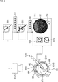
- FIG. 1 is a diagram for explaining eye surgery.
- An endoscopic endoscope 11 and a surgical instrument 12 are inserted into the eye 21 to be operated.
- An image 41 inside the operated eye 21 photographed by the intraocular endoscope 11 is displayed on the monitor 31.
- the surgeon performs an operation while viewing the image 41 on the monitor 31.
- the intraocular endoscope 11 has a high degree of freedom in the shooting position, but has a problem that it is easy to lose sight of the gravity direction and position of the image. Further, if the operation is mistaken, the retina 13 may be damaged.
- Patent Document 1 an index indicating a specific direction at the hand of the ophthalmic endoscope
- Patent Document 2 it has been proposed to use a gravity sensor or an acceleration sensor to determine the direction of the endoscope.
- Patent Document 3 it has been proposed to detect a marker from an X-ray image with an X-ray of an endoscope that observes the duodenum.
- the present technology has been made in view of such a situation, and makes it possible to easily grasp the position and direction of a surgical member for operating an eye.
- One aspect of the present technology is an acquisition unit that acquires a microscope image obtained by photographing a surgical member inserted into a surgical target with a surgical microscope, and the microscopic image acquired by the acquisition unit.
- An image processing apparatus comprising: an estimation unit that estimates a relative posture of the surgical member; and an output unit that outputs posture information related to the estimated posture.
- the surgical member can be an endoscopic endoscope.
- the output unit can superimpose and output the posture information on an endoscopic image output by the endoscopic endoscope.
- the posture may include at least one of a position, a direction, and a rotation angle.
- the posture information can include a figure representing a position, direction, or rotation angle on a scale.
- the posture information can include a cross-sectional or three-dimensional view of the eyeball model.
- a marker is displayed on the surgical member, and the estimation unit estimates a relative posture of the surgical member within the surgical target based on the marker of the microscope image acquired by the acquisition unit. be able to.
- the acquisition unit acquires an image obtained by photographing the endoscopic endoscope from the outside of the operated eye as the operation target, and the estimation unit is inserted into the operated eye of the endoscopic endoscope.
- the relative posture of the endoscopic endoscope in the operated eye can be estimated based on the feature amount of the missing part.
- the surgical member is a surgical instrument on which a marker is displayed
- the acquisition unit acquires the microscope image of the surgical instrument on which the marker is displayed and an endoscopic image of an endoscopic endoscope, and performs the estimation
- the unit estimates a relative posture between the surgical instrument on which the marker is displayed and the surgical microscope, and relative between the surgical instrument on which the marker is displayed and the endoscopic endoscope.
- a posture is estimated, and the surgical microscope and the endoscopic endoscope are obtained from a relative posture between the surgical tool and the surgical microscope and a relative posture between the surgical tool and the endoscopic endoscope. It is possible to further include a calculation unit that calculates a relative posture between the two.
- One aspect of the present technology provides a step of acquiring a microscope image obtained by photographing a surgical member inserted into a surgical target with a surgical microscope, and the microscopic image acquired by the acquiring unit, based on the microscopic image acquired in the surgical target.
- An image processing method includes a step of estimating a relative posture of a surgical member and a step of outputting posture information relating to the estimated posture.
- One aspect of the present technology provides a surgical microscope that images a surgical object, an acquisition unit that acquires a microscope image obtained by imaging the surgical member inserted into the surgical object using the surgical microscope, and the acquisition unit acquired by the acquisition unit
- the surgical operation system includes an estimation unit that estimates a relative posture of the surgical member in the surgical target based on a microscope image, and an output unit that outputs posture information related to the estimated posture.
- One aspect of the present technology is a surgical member that is inserted into a surgical eye of a surgeon and used for surgery of the surgical eye, and is observed with a surgical microscope at an insertion portion that is inserted into the surgical eye A surgical member on which possible markers are displayed.
- a microscope image obtained by photographing a surgical member inserted into a surgical target with a surgical microscope is acquired, and based on the acquired microscopic image, the relative posture of the surgical member within the surgical target Is estimated, and posture information relating to the estimated posture is output.
- the position and direction of the surgical member for operating the eye can be easily grasped.
- FIG. 2 is a perspective view showing a configuration of a surgery system according to an embodiment of the present technology.
- FIG. 2 schematically shows a basic configuration of a surgical operation system 100 for ophthalmic surgery.
- the surgical system 100 includes a surgical table 111, a surgical microscope 112, an image processing device 113, and a presentation unit 114.
- a vitrectomy device, a vital display device, and the like are used as necessary, but the illustration is omitted.
- the patient (that is, patient) 131 is laid on the surgical table 111.
- the operator 132 stands on the rear side (or may be the left side or the right side) of the head 131A of the operator 131 and performs an ophthalmic operation using an ophthalmic surgical member.
- an intraocular endoscope 121 and a surgical instrument 122 such as a vitreous cutter are used as a surgical member.
- the surgical microscope 112 is disposed above the head 131A of the operated person 131, and images the operated eye 151 (see FIG. 3 described later) as the operated object of the operated person 131.
- the endoscopic endoscope 121 and the surgical instrument 122 are inserted into the operated eye 151, the operated eye 151 in a state in which they are inserted is photographed.
- the image signal photographed by the surgical microscope 112 is supplied to the image processing device 113.
- the intraocular endoscope 121 is inserted into the eye to be operated 151, the internal state is photographed and the image signal is output to the image processing device 113.
- the image processing device 113 outputs an image corresponding to the input image signal to the presentation unit 114.
- the operator 132 can see an image (hereinafter referred to as a microscope image) taken with the surgical microscope 112 and an image (hereinafter referred to as an endoscopic image) taken with the endoscopic endoscope 121 during the operation.
- the surgical microscope 112 is equipped with a monitor so that the image can be viewed.
- the position of the surgical microscope 112 can be arbitrarily changed.
- the posture of the intraocular endoscope 121 can be changed by the operator 132 operating. Thereby, it is possible to observe an arbitrary part of the eye 151 to be operated.
- FIG. 3 is a diagram illustrating eye surgery according to an embodiment of the present technology.
- the principle of posture estimation of the intraocular endoscope 121 will be described with reference to FIG.
- FIG. 3 shows a cross-sectional configuration of the operated eye 151 of the operated person 131.
- the upper part of the operated eye 151 is covered with a cornea 161.
- a crystalline lens 162 exists in the deeper part of the anterior chamber 164 below the cornea 161, and an iris 163 exists on the left and right sides thereof. Further, a retina 165 exists behind the spherical operated eye 151.
- the insertion part 121A of the intraocular endoscope 121 is inserted into the operated eye 151, and the imaging part is illuminated with illumination light from the tip 121B, and the internal state is imaged.
- a marker 171 for confirming the posture of the endoscopic endoscope 121 is displayed on the insertion unit 121A. The marker 171 can be confirmed with a microscope image taken with the surgical microscope 112.
- FIG. 4 is a diagram illustrating a marker of the present technology.
- the marker Mx (x is a number) in FIG. 4 corresponds to the marker 171 in FIG.
- the insertion portion 121A of the intraocular endoscope 121 has bands of red, blue, green, and yellow colors on its outer surface, that is, so that it can be observed by a microscope image of the surgical microscope 112. It is displayed along the length direction of the insertion part 121A.
- the red band M1 is displayed on the upper side of the endoscope 121
- the blue band M2 is displayed at a position rotated 90 degrees counterclockwise from the red band M1.
- the green band M3 is displayed at a position rotated 180 degrees counterclockwise from the red band M1
- the yellow band M4 is displayed at a position rotated 270 degrees counterclockwise from the red band M1.
- the rotation angle of the endoscopic endoscope 121 can be estimated from a microscope image obtained by imaging the endoscopic endoscope 121 in which the insertion portion 121A is inserted into the operated eye 151 with the surgical microscope 112. For example, when the red band M1 is observed, the intraocular endoscope 121 is positioned at a reference position (a position where the red band M1 is disposed on the upper side), that is, the rotation angle is 0 degree. I understand. When the blue band M2 is observed, it can be seen that the intraocular endoscope 121 is rotated 90 degrees counterclockwise from the reference position.
- the rotation angle from the reference position of the endoscope 121 is 180 degrees
- the yellow band M4 is observed
- the intraocular endoscope It can be seen that the rotation angle from the reference position of the mirror 121 is 270 degrees.
- the red band M1 and the blue band M2 are observed, it can be seen that the rotation angle from the reference position of the endoscopic endoscope 121 is 45 degrees.
- FIG. 4B shows an example in which different numbers of lines are displayed as markers at predetermined positions.
- the number of lines of the marker M11 at the reference position is one
- the number of lines of the marker M2 at a position rotated 90 degrees counterclockwise from the reference position is two.
- the rotation angle of the intraocular endoscope 121 can be estimated from the observed marker state.
- FIG. 4C shows an example of markers with different line thicknesses.
- the line of the marker M21 at the reference position is the thinnest, and the line of the marker M22 at the position rotated 90 degrees counterclockwise from the reference position is thicker than the marker M21.
- the marker line at a position rotated 180 degrees counterclockwise from the reference position is thicker than the marker M22, and the marker line at a position rotated 270 degrees counterclockwise is 180 It is thicker than the marker at the degree position.
- the rotation angle of the intraocular endoscope 121 can be estimated from the observed marker state.
- D in FIG. 4 represents an example of a marker in which the line interval differs depending on the position. That is, in this example, a line having a different interval according to the rotation angle from the reference position of the intraocular endoscope 121 is displayed as the marker M31. In this example as well, the rotation angle of the intraocular endoscope 121 can be estimated from the observed marker state.
- FIG. 4E shows an example of a marker having a specific pattern.
- a two-dimensional barcode is displayed as a marker 41 on the insertion unit 121A.
- the rotation angle of the intraocular endoscope 121 can be estimated from the observed marker state.
- the microscope image 201 is obtained by photographing the eye 151 to be operated with the operation microscope 112.
- posture estimation processing 211 for estimating the posture of the intraocular endoscope 121 can be performed.
- a superimposition process 212 for superimposing the estimated posture on the image of the endoscopic endoscope 121 is executed.
- an endoscopic image 221 photographed by the intraocular endoscope 121 and graphic images 222, 223, and 224 representing the estimated posture of the intraocular endoscope 121 are displayed. Details of the graphic images 222, 223, and 224 representing the posture will be described later as posture information with reference to FIGS. 11 to 14.
- graphic images 222 and 223 representing the posture of the intraocular endoscope 121 and an arrow graphic image 224 indicating the direction of gravity are displayed on the cross-sectional graphic of the operated eye 151.
- FIG. 5 is a block diagram showing a functional configuration of the surgery system of the present technology.
- the surgical microscope 112 of the surgical system 100 includes a drive unit 301 and an imaging unit 302.
- the imaging unit 302 includes a camera and an illumination unit.
- the imaging unit 302 is moved to an arbitrary position with respect to the eye 151 to be operated by the driving unit 301 and performs imaging from that position.
- the intraocular endoscope 121 has a photographing unit 311 composed of a camera and an illumination unit.
- the photographing unit 311 can photograph the internal state of the endoscope 121.
- the image processing apparatus 113 includes an acquisition unit 321, a marker detection unit 322, a posture estimation unit 323, a feature amount database 324, an acquisition unit 325, and a superimposition unit 326.
- the acquisition unit 321 acquires an image signal of a microscope image obtained by imaging by the imaging unit 302 of the surgical microscope 112.
- the marker detection unit 322 detects the marker 171 from the image signal acquired by the acquisition unit 321.
- the posture estimation unit 323 estimates the posture of the intraocular endoscope 121 from the imaging state of the marker 171 detected by the marker detection unit 322.
- the feature amount database 324 holds in advance image information necessary for the posture estimation unit 323 to estimate the posture of the endoscope 121 from the shooting state of the marker 171.
- the posture estimation unit 323 outputs an image corresponding to the estimated posture.
- the feature quantity database 324 stores three-dimensional position information (feature points) of the endoscope 121 on which the marker 171 is displayed.
- feature points three-dimensional position information
- PNPP perspective N point problem
- the three-dimensional position and orientation of a typical camera the imaging unit 302 of the surgical microscope 112
- the three-dimensional position and posture of the feature point can be obtained using the position of the imaging unit 302 of the surgical microscope 112 as a reference, and the position and posture of the intraocular endoscope 121 can be obtained therefrom.
- information necessary for solving the PNPP including parameters such as the angle of view and the amount of distortion of the imaging unit 302 is stored in the feature amount database 324 in advance.
- the obtaining unit 325 obtains an endoscope image photographed by the photographing unit 311 of the intraocular endoscope 121.
- the superimposing unit 326 superimposes the image representing the posture from the posture estimating unit 323 and the endoscopic image of the intraocular endoscope 121 acquired by the acquiring unit 325, and outputs the superimposed image to the presenting unit 114 for presentation.
- FIG. 6 is a flowchart illustrating image processing according to the present technology.
- step S11 the acquisition unit 321 acquires a microscope image.
- the acquired image signal of the microscope image is supplied to the marker detection unit 322. That is, the operating eye 151 is imaged by the imaging unit 302 arranged in a predetermined position so that the entire operating eye 151 can be seen in advance by the drive unit 301.
- the marker 171 is reflected in the acquired microscope image.
- step S12 the marker detection unit 322 detects the intraocular endoscope 121. That is, the intraocular endoscope 121 is detected from the acquired microscope image taken by the imaging unit 302 of the surgical microscope 112. Note that detection accuracy can be improved by performing detection processing using past detection results.
- step S13 the marker detection unit 322 determines whether the detection is successful. If the marker 171 cannot be detected yet, the process returns to step S11. That is, the process of detecting the marker 171 from the acquired microscope image is repeated.
- the marker detection unit 322 supplies the detection result to the posture estimation unit 323.
- the posture estimation unit 323 estimates the posture of the intraocular endoscope 121.
- the state of the marker 171 in the microscope image obtained by photographing the intraocular endoscope 121 with the surgical microscope 112 varies depending on the posture of the intraocular endoscope 121.
- the feature amount database 324 stores an image of the marker 171 corresponding to an arbitrary rotation angle, and searches the stored image of the marker 171 for an image corresponding to the observed image of the marker 171.
- the rotation angle of the intraocular endoscope 121 can be estimated.
- the posture of the intraocular endoscope 121 is specified by the position and direction in addition to the rotation angle (rotation amount).
- the position and direction can be estimated by solving PNPP.
- step S15 the posture estimation unit 323 determines whether the estimation is successful. If the posture of the intraocular endoscope 121 cannot be estimated yet, the process returns to step S11, and the subsequent processes are repeated.
- the posture estimation unit 323 When the posture of the endoscope 121 can be estimated, the posture estimation unit 323 generates posture information in step S16. That is, posture information corresponding to the estimated posture is generated. Details of the posture information will be described later with reference to FIGS.
- step S17 the superimposing unit 326 executes the superimposing process. That is, the superimposing unit 326 superimposes an image corresponding to the posture estimated by the posture estimating unit 323 on the endoscope image captured by the imaging unit 311 of the intraocular endoscope 121 acquired by the acquiring unit 325.
- the presentation unit 114 presents information. That is, an endoscopic image photographed by the intraocular endoscope 121 and an image corresponding to the posture estimated by the posture estimation unit 323 are presented to the presentation unit 114.
- the operator 132 can confirm the posture of the endoscope 121 based on the presented information. Therefore, the operator 132 can operate safely by operating the endoscopic endoscope 121 as necessary, confirming a desired site, and operating the surgical instrument 122.
- Second Embodiment> In the first embodiment, the marker 171 is displayed on the insertion portion 121 ⁇ / b> A of the intraocular endoscope 121, and the posture of the intraocular endoscope 121 is estimated by observing the marker 171. In the second embodiment, the posture is estimated from the feature amount outside the endoscope 121 without adding the marker 171.
- the second embodiment will be described with reference to FIG.
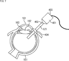
- FIG. 7 is a diagram illustrating eye surgery according to an embodiment of the present technology.
- FIG. 7 shows a state in which the insertion portion 121A of the intraocular endoscope 121 is inserted from the trocar 404 into the operated eye 151.
- a thick handle 401 is attached via a frustoconical joint portion 402.
- the handle 401 is provided with an edge for preventing slipping, and a cable 403 is connected thereto.
- the configuration of the surgical system 100 of the second embodiment is basically the same as that of the first embodiment.
- the angle of view is changed so that a wider range can be imaged, for example, by disposing the surgical microscope 112 at a position farther from the eye 151 to be operated than in the case of the first embodiment.
- a wide-angle lens can be used.
- a member located outside the operated eye 151 other than the insertion portion 121A, such as the handle 401, the joint portion 402, the cable 403, and the trocar 404, is photographed. Detected and learned.
- an image pickup unit different from the operation microscope 112 may be provided to detect the feature amount of the external member. Therefore, in the case of the second embodiment, the feature amount database 324 stores feature amounts necessary to estimate the purification of the endoscope 121 from the feature amounts of the external members.
- the operation of the second embodiment is the same as that of the first embodiment, the description thereof is omitted.
- the types of the intraocular endoscope 121 that can be used increase.
- FIG. 8 is a diagram illustrating eye surgery according to an embodiment of the present technology. Next, a third embodiment will be described with reference to FIG.
- FIG. 8 shows a cross-sectional configuration of the operated eye 151 of the operated person 131, as in FIG.
- the upper part of the operated eye 151 is covered with a cornea 161.
- a crystalline lens 162 exists in the deeper part of the anterior chamber 164 below the cornea 161, and an iris 163 exists on the left and right sides thereof. Further, a retina 165 exists behind the spherical operated eye 151.
- the insertion part 121A of the endoscopic endoscope 121 is inserted into the operated eye 151, and the internal state is photographed. Further, the insertion portion 122A of the surgical instrument 122 is also inserted into the operated eye 151.
- the marker 171 is displayed on the insertion portion 121 ⁇ / b> A of the intraocular endoscope 121.
- a marker 181 for confirming the posture of the surgical instrument 122 is displayed on the insertion portion 122A of the surgical instrument 122. The marker 181 can be confirmed with a microscope image taken with the surgical microscope 112 and an endoscope image taken with the intraocular endoscope 121.
- the marker 181 is the same as the marker 171 already described with reference to FIG. 4 and will not be described because it is repeated.
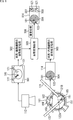
- the microscope image 501 is obtained by photographing the eye 151 to be operated with the surgical microscope 112.
- posture estimation processing 502 for estimating the posture of the surgical instrument 122 relative to the surgical microscope 112 can be performed.
- an endoscopic image 504 is obtained by photographing the eye 151 to be operated with the endoscopic endoscope 121.
- posture estimation processing 505 for estimating the posture of the surgical instrument 122 relative to the endoscopic endoscope 121 can be performed.
- the posture conversion processing 503 on the posture of the surgical tool 122 relative to the surgical microscope 112 and the posture of the surgical tool 122 relative to the intraocular endoscope 121, the relative relationship of the intraocular endoscope 121 relative to the surgical microscope 112 is achieved. You can get a posture.
- an endoscopic image 504 photographed by the intraocular endoscope 121 and graphic images 507 and 508 representing the estimated posture of the intraocular endoscope 121 are displayed. Details of the graphic images 507 and 508 representing the posture will be described later as posture information.
- graphic images 507 and 508 representing the posture of the endoscope 121 are displayed on the cross-sectional shape of the operated eye 151. Has been.
- FIG. 9 is a block diagram showing a functional configuration of the surgery system of the present technology.
- the operating microscope 112 has a drive unit 301 and an imaging unit 302
- the intraocular endoscope 121 has an imaging unit 311 in the first embodiment of FIG. It is the same as the case of the form.
- the image processing apparatus 113 also includes an acquisition unit 321 that processes a signal from the imaging unit 302 of the surgical microscope 112, a marker detection unit 322, a posture estimation unit 323, and a feature amount database 324 according to the first embodiment. It is the same as the case of.
- the acquisition unit 325 that acquires the output of the imaging unit 311 of the endoscope 121 and the superimposition unit 326 that superimposes the output of the acquisition unit 325 on the posture information are also included in the case of the first embodiment. It is the same.
- a system for processing a signal from the intraocular endoscope 121 is provided. That is, an acquisition unit 325, a marker detection unit 601, and a posture estimation unit 602 are provided as a system for processing a signal from the imaging unit 311 of the intraocular endoscope 121.
- the obtaining unit 325 obtains an image signal of an endoscope image obtained by photographing by the photographing unit 311 of the endoscopic endoscope 121.
- the marker detection unit 601 detects the marker 181 from the image signal of the endoscopic image acquired by the acquisition unit 325.
- the posture estimation unit 602 estimates the posture of the surgical instrument 122 from the imaging state of the marker 181 detected by the marker detection unit 601.
- the feature amount database 324 stores not only the feature amount of the posture of the marker 181 with respect to the surgical microscope 112 displayed on the insertion unit 122A of the surgical instrument 122 but also the feature amount of the posture of the marker 181 with respect to the endoscope 121. ing.
- the posture estimation unit 602 detects the posture of the surgical tool 122 relative to the endoscope 121 in the same manner as the posture estimation unit 323 detects the posture of the surgical tool 122 relative to the surgical microscope 112.
- the image processing apparatus 113 is provided with a calculation unit 603 that executes posture conversion processing 503.
- the calculation unit 603 determines the surgical tool 122 with respect to the surgical microscope 112 based on the posture of the surgical tool 122 estimated by the posture estimation unit 323 and the posture of the surgical tool 122 with respect to the intraocular endoscope 121 estimated by the posture estimation unit 602.
- the posture of the intraocular endoscope 121 is calculated.
- the superimposing unit 326 superimposes the image representing the posture of the intraocular endoscope 121 supplied from the computing unit 603 and the endoscopic image of the intraocular endoscope 121 acquired by the acquiring unit 325 to provide a presentation unit. It outputs to 114 and makes it present.
- FIG. 10 is a flowchart illustrating image processing according to the present technology.
- step S51 the acquisition unit 321 acquires a microscope image.
- the acquired image signal of the microscope image is supplied to the marker detection unit 322. That is, the eye 151 to be operated is imaged by the imaging unit 302 that is previously arranged at a predetermined position by the drive unit 301. As shown in FIG. 8, when the insertion portion 122A of the surgical instrument 122 is inserted into the eye 151 to be operated, the marker 181 is reflected in the acquired microscope image.
- step S52 the marker detection unit 322 detects the surgical instrument 122. That is, the surgical instrument 122 is detected from the acquired microscope image taken by the imaging unit 302 of the surgical microscope 112.
- step S53 the marker detection unit 322 determines whether the detection is successful. If the marker 181 cannot be detected, the process returns to step S51. That is, the process of detecting the marker 181 from the acquired image is repeated.
- the marker detection unit 322 supplies the detection result to the posture estimation unit 323.
- the posture estimation unit 323 estimates the posture of the surgical instrument 122 viewed from the surgical microscope 112.
- the state of the marker 181 in the microscope image obtained by photographing the surgical instrument 122 with the surgical microscope 112 changes depending on the posture of the surgical instrument 122.
- the feature quantity database 324 stores an image of the marker 181 corresponding to an arbitrary rotation angle, and searches the stored image of the marker 181 for an image corresponding to the observed image of the marker 181.
- the rotation angle of the surgical instrument 122 viewed from the surgical microscope 112 can be estimated.
- the position and direction can be estimated by solving PNPP. That is, the same processing as in step S14 of FIG. 6 is executed.
- step S55 the posture estimation unit 323 determines whether the estimation is successful. If the posture of the surgical instrument 122 cannot be estimated yet, the process returns to step S51, and the subsequent processes are repeated.
- step S56 If the posture of the surgical instrument 122 has been estimated, the process proceeds to step S56.
- step S56 the acquisition unit 325 acquires an endoscopic image.
- the acquired image signal of the endoscopic image is supplied to the marker detection unit 601. That is, a predetermined part of the operated eye 151 is imaged by the imaging unit 311 of the intraocular endoscope 121 arranged at a predetermined position by the operation of the operator 132. As shown in FIG. 8, when the insertion portion 122A of the surgical instrument 122 is inserted into the eye 151 to be operated, the marker 181 is reflected in the acquired endoscopic image.
- step S57 the marker detection unit 601 detects the surgical instrument 122.
- the surgical instrument 122 is detected from the acquired endoscopic image captured by the imaging unit 311 of the acquired endoscopic endoscope 121.
- step S58 the marker detection unit 601 determines whether the detection is successful. If the marker 181 cannot be detected, the process returns to step S56. That is, the process of detecting the marker 181 from the acquired endoscopic image is repeated.
- the marker detection unit 601 supplies the detection result to the posture estimation unit 602.
- the posture estimation unit 602 estimates the posture of the surgical instrument 122 viewed from the intraocular endoscope 121.
- the state of the marker 181 in the image obtained by photographing the surgical instrument 122 with the intraocular endoscope 121 varies depending on the posture of the surgical instrument 122.
- the feature quantity database 324 stores an image of the marker 181 corresponding to an arbitrary rotation angle, and searches the stored image of the marker 181 for an image corresponding to the observed image of the marker 181.
- the rotation angle of the surgical instrument 122 viewed from the intraocular endoscope 121 can be estimated.
- the position and direction can be estimated by solving PNPP. That is, the same processing as in step S14 of FIG. 6 and step S54 of FIG. 10 is executed.
- step S60 the posture estimation unit 602 determines whether the estimation is successful. If the posture of the surgical instrument 122 cannot be estimated yet, the process returns to step S56, and the subsequent processes are repeated.
- processing for the microscope image of the surgical microscope 112 in steps S51 to S55 and the processing for the endoscope image of the endoscopic endoscope 121 in steps S56 to S60 can be performed in reverse order. In practice, these processes are executed simultaneously in parallel.
- step S60 When the posture of the surgical tool 122 viewed from the intraocular endoscope 121 in step S60 can be estimated, that is, the posture of the surgical tool 122 viewed from the surgical microscope 112 and the surgical tool 122 viewed from the intraocular endoscope 121. If both of the postures can be estimated, the process of step S61 is executed next.
- step S ⁇ b> 61 the calculation unit 603 calculates the posture of the endoscope 121 viewed from the surgical microscope 112. In other words, the posture of the surgical tool 122 viewed from the surgical microscope 112 and the posture of the surgical tool 122 viewed from the intraocular endoscope 121 are converted into the posture of the intraocular endoscope 121 viewed from the surgical microscope 112.
- step S62 the calculation unit 603 generates posture information. That is, posture information corresponding to the calculated posture is generated. Details of the posture information will be described later with reference to FIGS.
- step S63 the superimposing unit 326 executes a superimposing process. That is, the superimposing unit 326 superimposes an image corresponding to the posture calculated by the calculating unit 603 on the endoscopic image captured by the imaging unit 311 of the intraocular endoscope 121 acquired by the acquiring unit 325, It supplies to the presentation part 114.
- the presenting unit 114 presents information. That is, an endoscope image captured by the intraocular endoscope 121 and an image corresponding to the posture calculated by the calculation unit 603 are presented to the presentation unit 114.
- the operator 132 can confirm the posture of the endoscope 121 based on the presented information. Therefore, the operator 132 can safely perform the operation by appropriately performing necessary operations on the intraocular endoscope 121.
- retina 165 itself has a characteristic pattern due to blood vessels, this pattern may be used as a characteristic point instead of the surgical instrument 122.
- posture information will be described with reference to FIGS.
- the surgeon 132 can see the posture information, confirm the posture of the endoscopic endoscope 121, and appropriately operate the endoscopic endoscope 121.
- 11 to 14 are diagrams illustrating examples of posture information of the present technology.
- FIG. 11A an endoscopic image 611 obtained by photographing with the intraocular endoscope 121 is displayed.
- the endoscopic image 611 shows the surgical instrument 122.
- An arrow graphic 701 is displayed as posture information in the vicinity of the outer peripheral end of the endoscopic image 611.
- the arrow graphic 701 indicates the direction of gravity of the intraocular endoscope 121, that is, in this example, if the intraocular endoscope 121 is not rotating, the arrow graphic 701 indicates the downward direction. Therefore, the operator 132 can recognize from FIG. 11A that the endoscopic endoscope 121 is slightly rotated clockwise.
- an indicator such as a compass that indicates the direction of gravity is displayed in a figure 702 that indicates a three-dimensional direction.
- the specific direction can be the direction designated by the operator 132, the ceiling direction, the direction of the surgical microscope 112, and the like in addition to the gravity direction.
- the operator 132 can be instructed at which angle a specific direction is present at a predetermined timing, and the presentation can be performed using the deviation based on that. Further, when the relative position and posture of the surgical microscope 112 and the intraocular endoscope 121 are known, the specific direction can be calculated from the position of the surgical microscope 112 as a reference.
- the direction in which the surgical instrument 122 detected from the microscope image of the surgical microscope 112 is present can be presented, or a reference site such as the fovea of the eye 151 to be operated can be set as a specific direction.
- three-dimensional posture information as shown in FIG. 11B can be used.
- FIG. 12 the amount of deviation from a specific direction is displayed.
- a roll angle scale of 0 degrees to 360 degrees is displayed at the outer peripheral end of the endoscopic image 611.
- a straight line 711 is displayed at an angle corresponding to the rotation angle of the endoscopic endoscope 121.
- the operator 132 can recognize the roll angle of the endoscope 121 from the angle on the scale indicated by the straight line 711.
- a straight line 711 is displayed so that the roll angle based on the horizontal direction can be seen.
- the roll angle scale (number representing the angle) is not displayed. Since the horizontal direction is the reference direction, the roll angle can be intuitively recognized.
- a scale 722 representing the distance to the retina is displayed in the vertical direction.
- An arrow graphic 721 is displayed at a position corresponding to the distance between the distal end 121B of the intraocular endoscope 121 and the retina 165. Therefore, the operator 132 can know the position of the endoscope 121 (that is, the distance from the tip 121B to the retina 165) by reading the scale value indicated by the arrow graphic 721. The risk of damage is reduced.
- an angle scale 732 with respect to the head 131A of the operator 131 is displayed below the endoscopic image 611.
- An arrow graphic 731 represents an angle from a reference position of the head 131A of the endoscopic endoscope 121 (for example, a center line passing through the top of the head 131A).
- the eyeball model may be created based on an actual three-dimensional image used in advance in OCT (Optical Coherence Tomography) photography or a general eyeball model.
- OCT Optical Coherence Tomography
- information is displayed by a schematic cross-sectional view of an eyeball model. That is, the figure 801 represents a vertical section of the eyeball model, and a figure 802 corresponding to the position and direction of the endoscope 121 is displayed there.
- a figure 811 represents a horizontal section of the eyeball model, and a figure 812 corresponding to the position and direction of the endoscope 121 is displayed there.
- the operator 132 can recognize the position and direction of the endoscopic endoscope 121 from these figures 801 and 802.
- FIG. 14 shows an example of three-dimensional display of posture information based on the eyeball model.
- a figure 902 corresponding to the position and direction of the endoscopic endoscope 121 is displayed on a three-dimensional eyeball model 901.
- the operator 132 can recognize the position and direction of the endoscopic endoscope 121.
- the orientation of the endoscopic image and the position and posture of the intraocular endoscope 121 can be determined. As a result, operability is improved and safe operation is possible. Even beginners can use it easily and learn operations in a short time. And the operation time is shortened.
- the insertion part 121A (fiber part) of the endoscopic endoscope 121 is resistant to distortion. Moreover, the diameter reduction is not inhibited.
- the present technology can be configured as follows. (1) An acquisition unit for acquiring a microscope image obtained by photographing a surgical member inserted into a surgical object with a surgical microscope; Based on the microscope image acquired by the acquisition unit, an estimation unit that estimates a relative posture of the surgical member within the surgical target; An image processing apparatus comprising: an output unit that outputs posture information related to the estimated posture. (2) The image processing apparatus according to (1), wherein the surgical member is an endoscopic endoscope. (3) The image processing apparatus according to (1) or (2), wherein the output unit superimposes and outputs the posture information on an endoscopic image output by the endoscopic endoscope.
- the image processing apparatus includes at least one of a position, a direction, and a rotation angle.
- the posture information includes a diagram representing a position, a direction, or a rotation angle on a scale.
- the posture information includes a cross-sectional or three-dimensional view of an eyeball model.
- a marker is displayed on the surgical member, The estimation unit estimates a relative posture of the surgical member in the surgical target based on the marker of the microscope image acquired by the acquisition unit. Any one of (1) to (6) An image processing apparatus according to 1.
- the acquisition unit acquires an image obtained by photographing the endoscopic endoscope from the outside of the operated eye as the operation target, The estimation unit estimates a relative posture of the endoscopic endoscope in the operated eye based on a feature amount of a portion of the endoscopic endoscope that is not inserted into the operated eye.
- the image processing apparatus according to any one of (7).
- the surgical member is a surgical instrument on which a marker is displayed, The acquisition unit acquires the microscopic image of the surgical instrument on which the marker is displayed and an endoscopic image of an endoscopic endoscope, The estimation unit estimates a relative posture between the surgical instrument on which the marker is displayed and the surgical microscope, and a relative position between the surgical instrument on which the marker is displayed and the endoscopic endoscope.
- the image processing apparatus according to any one of (1) to (8), further including a calculation unit that calculates a correct posture.
- a surgical microscope for imaging the surgical object An acquisition unit for acquiring a microscope image obtained by photographing the surgical member inserted into the surgical object with the surgical microscope; Based on the microscope image acquired by the acquisition unit, an estimation unit that estimates a relative posture of the surgical member within the surgical target; An operation system comprising: an output unit that outputs posture information related to the estimated posture.
- a surgical member that is inserted into the surgical eye of the surgical subject and used for surgery of the surgical eye A surgical member in which a marker that can be observed with a surgical microscope is displayed on an insertion portion that is inserted into the eye to be operated.
Landscapes
- Health & Medical Sciences (AREA)
- Life Sciences & Earth Sciences (AREA)
- Surgery (AREA)
- Engineering & Computer Science (AREA)
- Public Health (AREA)
- Veterinary Medicine (AREA)
- Biomedical Technology (AREA)
- Heart & Thoracic Surgery (AREA)
- Animal Behavior & Ethology (AREA)
- General Health & Medical Sciences (AREA)
- Nuclear Medicine, Radiotherapy & Molecular Imaging (AREA)
- Medical Informatics (AREA)
- Molecular Biology (AREA)
- Ophthalmology & Optometry (AREA)
- Physics & Mathematics (AREA)
- Biophysics (AREA)
- Pathology (AREA)
- Optics & Photonics (AREA)
- Radiology & Medical Imaging (AREA)
- Robotics (AREA)
- Vascular Medicine (AREA)
- Oral & Maxillofacial Surgery (AREA)
- Signal Processing (AREA)
- Endoscopes (AREA)
- Microscoopes, Condenser (AREA)
Abstract
Description
1.第1の実施の形態
(1)手術システム
(2)姿勢推定の原理
(3)手術システムの機能ブロック
(4)画像処理
2.第2の実施の形態
3.第3の実施の形態
(1)姿勢推定の原理
(2)手術システムの機能ブロック
(3)画像処理
4.姿勢情報
5.その他
(1)手術システム
図2は、本技術の一実施の形態の手術システムの構成を示す斜視図である。この図2は、眼科手術用の手術システム100の基本的な構成を模式的に表している。手術システム100は、手術テーブル111、手術顕微鏡112、画像処理装置113および呈示部114により構成されている。この他、必要に応じて硝子体手術装置、バイタル表示装置等も用いられるが、図示は省略されている。
図3は、本技術の一実施の形態の眼の手術を説明する図である。以下、図3を参照して眼内内視鏡121の姿勢推定の原理について説明する。
図5は、本技術の手術システムの機能的構成を示すブロック図である。図5に示されるように、手術システム100の手術顕微鏡112は、駆動部301と撮影部302を有する。撮影部302はカメラと照明部により構成され、駆動部301により被手術眼151に対して任意の位置に移動され、その位置から撮影を行う。
次に図6を参照して図5の手術システム100の動作について説明する。図6は本技術の画像処理を説明するフローチャートである。
第1の実施の形態においては、眼内内視鏡121の挿入部121Aにマーカ171を表示し、マーカ171を観察することで眼内内視鏡121の姿勢を推定するようにした。第2の実施の形態においては、マーカ171を付加しないで眼内内視鏡121の外部の特徴量から姿勢が推定される。以下、図7を参照して第2の実施の形態について説明する。
図8は、本技術の一実施の形態の眼の手術を説明する図である。次に図8を参照して、第3の実施の形態について説明する。
図8には、図3における場合と同様に、被手術者131の被手術眼151の断面構成が示されている。被手術眼151の上方は角膜161により覆われている。角膜161の下の前房164のさらに奥には水晶体162が存在し、その左右には虹彩163が存在する。さらに球状の被手術眼151の奥には、網膜165が存在する。
図9は、本技術の手術システムの機能的構成を示すブロック図である。図9に示されるように、手術顕微鏡112は、駆動部301と撮影部302を有し、眼内内視鏡121は撮影部311を有していることは、図5の第1の実施の形態の場合と同様である。また、画像処理装置113が、手術顕微鏡112の撮像部302からの信号を処理する取得部321、マーカ検出部322、姿勢推定部323、特徴量データベース324を有することも、第1の実施の形態の場合と同様である。さらに眼内内視鏡121の撮像部311の出力を取得する取得部325、および取得部325の出力を、姿勢情報と重畳する重畳部326を有することも、第1の実施の形態の場合と同様である。
次に図10を参照して図9の手術システム100の動作について説明する。図10は本技術の画像処理を説明するフローチャートである。
次に図11乃至図14を参照して姿勢情報について説明する。術者132は、この姿勢情報を見て、眼内内視鏡121の姿勢を確認し、眼内内視鏡121を適正に操作することができる。図11乃至図14は、いずれも本技術の姿勢情報の例を示す図である。
本技術は、以下のような構成もとることができる。
(1)
手術対象に挿入された手術用部材を手術顕微鏡により撮影した顕微鏡画像を取得する取得部と、
前記取得部により取得された前記顕微鏡画像に基づいて、前記手術対象内における前記手術用部材の相対的な姿勢を推定する推定部と、
推定された前記姿勢に関する姿勢情報を出力する出力部と
を備える画像処理装置。
(2)
前記手術用部材は眼内内視鏡である
前記(1)に記載の画像処理装置。
(3)
前記出力部は、前記眼内内視鏡が出力する内視鏡画像に前記姿勢情報を重畳して出力する
前記(1)または(2)に記載の画像処理装置。
(4)
前記姿勢は、位置、方向、または回転角の少なくとも1つを含む
前記(1)、(2)または(3)に記載の画像処理装置。
(5)
前記姿勢情報は、位置、方向、または回転角をスケール上に表す図を含む
前記(1)乃至(4)のいずれかに記載の画像処理装置。
(6)
前記姿勢情報は、眼球モデルの断面的または3次元的図を含む
前記(1)乃至(5)のいずれかに記載の画像処理装置。
(7)
前記手術用部材にはマーカが表示され、
前記推定部は、前記取得部により取得された前記顕微鏡画像の前記マーカに基づいて、前記手術対象内における前記手術用部材の相対的な姿勢を推定する
前記(1)乃至(6)のいずれかに記載の画像処理装置。
(8)
前記取得部は、前記眼内内視鏡を前記手術対象としての被手術眼の外側から撮影した画像を取得し、
前記推定部は、前記眼内内視鏡の前記被手術眼に挿入されていない部分の特徴量に基づいて、前記被手術眼内における前記眼内内視鏡の相対的な姿勢を推定する
前記(1)乃至(7)のいずれかに記載の画像処理装置。
(9)
前記手術用部材はマーカが表示された術具であり、
前記取得部は、前記マーカが表示された前記術具の前記顕微鏡画像と眼内内視鏡の内視鏡画像を取得し、
前記推定部は、前記マーカが表示された前記術具と前記手術顕微鏡の間の相対的な姿勢を推定するとともに、前記マーカが表示された前記術具と前記眼内内視鏡の間の相対的な姿勢を推定し、
前記術具と前記手術顕微鏡の間の相対的な姿勢と、前記術具と前記眼内内視鏡の間の相対的な姿勢から、前記手術顕微鏡と前記眼内内視鏡の間の相対的な姿勢を演算する演算部をさらに備える
前記(1)乃至(8)のいずれかに記載の画像処理装置。
(10)
手術対象に挿入された、挿入部にマーカが表示された手術用部材を手術顕微鏡により撮影した顕微鏡画像を取得するステップと、
前記取得部により取得された前記顕微鏡画像に基づいて、前記手術対象内における前記手術用部材の相対的な姿勢を推定するステップと、
推定された前記姿勢に関する姿勢情報を出力するステップと
を含む画像処理方法。
(11)
手術対象を撮影する手術顕微鏡と、
前記手術対象に挿入された手術用部材を前記手術顕微鏡により撮影した顕微鏡画像を取得する取得部と、
前記取得部により取得された前記顕微鏡画像に基づいて、前記手術対象内における前記手術用部材の相対的な姿勢を推定する推定部と、
推定された前記姿勢に関する姿勢情報を出力する出力部と
を備える手術システム。
(12)
被手術者の被手術眼に挿入され、前記被手術眼の手術に用いられる手術用部材であって、
前記被手術眼に挿入される挿入部に、手術顕微鏡で観察可能なマーカが表示されている
手術用部材。
Claims (12)
- 手術対象に挿入された手術用部材を手術顕微鏡により撮影した顕微鏡画像を取得する取得部と、
前記取得部により取得された前記顕微鏡画像に基づいて、前記手術対象内における前記手術用部材の相対的な姿勢を推定する推定部と、
推定された前記姿勢に関する姿勢情報を出力する出力部と
を備える画像処理装置。 - 前記手術用部材は眼内内視鏡である
請求項1に記載の画像処理装置。 - 前記出力部は、前記眼内内視鏡が出力する内視鏡画像に前記姿勢情報を重畳して出力する
請求項2に記載の画像処理装置。 - 前記姿勢は、位置、方向、または回転角の少なくとも1つを含む
請求項3に記載の画像処理装置。 - 前記姿勢情報は、位置、方向、または回転角をスケール上に表す図を含む
請求項4に記載の画像処理装置。 - 前記姿勢情報は、眼球モデルの断面的または3次元的図を含む
請求項5に記載の画像処理装置。 - 前記手術用部材にはマーカが表示され、
前記推定部は、前記取得部により取得された前記顕微鏡画像の前記マーカに基づいて、前記手術対象内における前記手術用部材の相対的な姿勢を推定する
請求項1に記載の画像処理装置。 - 前記取得部は、前記眼内内視鏡を前記手術対象としての被手術眼の外側から撮影した画像を取得し、
前記推定部は、前記眼内内視鏡の前記被手術眼に挿入されていない部分の特徴量に基づいて、前記被手術眼内における前記眼内内視鏡の相対的な姿勢を推定する
請求項2に記載の画像処理装置。 - 前記手術用部材はマーカが表示された術具であり、
前記取得部は、前記マーカが表示された前記術具の前記顕微鏡画像と眼内内視鏡の内視鏡画像を取得し、
前記推定部は、前記マーカが表示された前記術具と前記手術顕微鏡の間の相対的な姿勢を推定するとともに、前記マーカが表示された前記術具と前記眼内内視鏡の間の相対的な姿勢を推定し、
前記術具と前記手術顕微鏡の間の相対的な姿勢と、前記術具と前記眼内内視鏡の間の相対的な姿勢から、前記手術顕微鏡と前記眼内内視鏡の間の相対的な姿勢を演算する演算部をさらに備える
請求項1に記載の画像処理装置。 - 手術対象に挿入された手術用部材を手術顕微鏡により撮影した顕微鏡画像を取得するステップと、
前記取得部により取得された前記顕微鏡画像に基づいて、前記手術対象内における前記手術用部材の相対的な姿勢を推定するステップと、
推定された前記姿勢に関する姿勢情報を出力するステップと
を含む画像処理方法。 - 手術対象を撮影する手術顕微鏡と、
前記手術対象に挿入された手術用部材を前記手術顕微鏡により撮影した顕微鏡画像を取得する取得部と、
前記取得部により取得された前記顕微鏡画像に基づいて、前記手術対象内における前記手術用部材の相対的な姿勢を推定する推定部と、
推定された前記姿勢に関する姿勢情報を出力する出力部と
を備える手術システム。 - 被手術者の被手術眼に挿入され、前記被手術眼の手術に用いられる手術用部材であって、
前記被手術眼に挿入される挿入部に、手術顕微鏡で観察可能なマーカが表示されている
手術用部材。
Priority Applications (4)
| Application Number | Priority Date | Filing Date | Title |
|---|---|---|---|
| JP2018509008A JPWO2017169823A1 (ja) | 2016-03-30 | 2017-03-16 | 画像処理装置および方法、手術システム並びに手術用部材 |
| US16/075,018 US11135020B2 (en) | 2016-03-30 | 2017-03-16 | Image processing device and method, surgical system, and surgical member |
| CN201780009856.7A CN108601670B (zh) | 2016-03-30 | 2017-03-16 | 图像处理装置和方法、手术系统和手术构件 |
| EP17774367.1A EP3437593B1 (en) | 2016-03-30 | 2017-03-16 | Image processing device and method, surgery system, and surgical member |
Applications Claiming Priority (2)
| Application Number | Priority Date | Filing Date | Title |
|---|---|---|---|
| JP2016067416 | 2016-03-30 | ||
| JP2016-067416 | 2016-03-30 |
Publications (1)
| Publication Number | Publication Date |
|---|---|
| WO2017169823A1 true WO2017169823A1 (ja) | 2017-10-05 |
Family
ID=59964420
Family Applications (1)
| Application Number | Title | Priority Date | Filing Date |
|---|---|---|---|
| PCT/JP2017/010579 Ceased WO2017169823A1 (ja) | 2016-03-30 | 2017-03-16 | 画像処理装置および方法、手術システム並びに手術用部材 |
Country Status (5)
| Country | Link |
|---|---|
| US (1) | US11135020B2 (ja) |
| EP (1) | EP3437593B1 (ja) |
| JP (1) | JPWO2017169823A1 (ja) |
| CN (1) | CN108601670B (ja) |
| WO (1) | WO2017169823A1 (ja) |
Cited By (8)
| Publication number | Priority date | Publication date | Assignee | Title |
|---|---|---|---|---|
| EP3506302A1 (en) * | 2017-12-28 | 2019-07-03 | Ethicon LLC | Usage and technique analysis of surgeon / staff performance against a baseline to optimize device utilization and performance for both current and future procedures |
| WO2019230173A1 (ja) * | 2018-05-30 | 2019-12-05 | ソニー株式会社 | 画像処理装置、画像処理方法及び眼内画像処理システム |
| JP6993043B1 (ja) * | 2020-10-27 | 2022-01-13 | リバーフィールド株式会社 | 手術支援装置 |
| JP7026988B1 (ja) * | 2020-10-27 | 2022-03-01 | リバーフィールド株式会社 | 手術支援装置 |
| JP7029216B1 (ja) * | 2020-10-27 | 2022-03-03 | リバーフィールド株式会社 | 手術支援装置 |
| JP2022116440A (ja) * | 2021-01-29 | 2022-08-10 | ソニー・オリンパスメディカルソリューションズ株式会社 | 医療用画像処理装置及び医療用観察システム |
| JP2022543272A (ja) * | 2019-08-06 | 2022-10-11 | アルコン インコーポレイティド | 硝子体網膜手術用のシーンカメラシステム及び方法 |
| JP2023003261A (ja) * | 2021-06-23 | 2023-01-11 | 富士フイルム株式会社 | 医療画像処理装置及びその作動方法並びに内視鏡システム |
Families Citing this family (134)
| Publication number | Priority date | Publication date | Assignee | Title |
|---|---|---|---|---|
| US11871901B2 (en) | 2012-05-20 | 2024-01-16 | Cilag Gmbh International | Method for situational awareness for surgical network or surgical network connected device capable of adjusting function based on a sensed situation or usage |
| US11504192B2 (en) | 2014-10-30 | 2022-11-22 | Cilag Gmbh International | Method of hub communication with surgical instrument systems |
| US11071449B2 (en) * | 2016-03-31 | 2021-07-27 | Alcon Inc. | Visualization system for ophthalmic surgery |
| US12262866B2 (en) * | 2017-09-22 | 2025-04-01 | Carl Zeiss Meditec Ag | Visualization system comprising an observation apparatus and an endoscope |
| US11311342B2 (en) | 2017-10-30 | 2022-04-26 | Cilag Gmbh International | Method for communicating with surgical instrument systems |
| US11291510B2 (en) | 2017-10-30 | 2022-04-05 | Cilag Gmbh International | Method of hub communication with surgical instrument systems |
| US11510741B2 (en) | 2017-10-30 | 2022-11-29 | Cilag Gmbh International | Method for producing a surgical instrument comprising a smart electrical system |
| US11051836B2 (en) | 2017-10-30 | 2021-07-06 | Cilag Gmbh International | Surgical clip applier comprising an empty clip cartridge lockout |
| US11564756B2 (en) | 2017-10-30 | 2023-01-31 | Cilag Gmbh International | Method of hub communication with surgical instrument systems |
| US11141160B2 (en) | 2017-10-30 | 2021-10-12 | Cilag Gmbh International | Clip applier comprising a motor controller |
| US11801098B2 (en) | 2017-10-30 | 2023-10-31 | Cilag Gmbh International | Method of hub communication with surgical instrument systems |
| US11911045B2 (en) | 2017-10-30 | 2024-02-27 | Cllag GmbH International | Method for operating a powered articulating multi-clip applier |
| US11229436B2 (en) | 2017-10-30 | 2022-01-25 | Cilag Gmbh International | Surgical system comprising a surgical tool and a surgical hub |
| US11317919B2 (en) | 2017-10-30 | 2022-05-03 | Cilag Gmbh International | Clip applier comprising a clip crimping system |
| US11304720B2 (en) | 2017-12-28 | 2022-04-19 | Cilag Gmbh International | Activation of energy devices |
| US11818052B2 (en) | 2017-12-28 | 2023-11-14 | Cilag Gmbh International | Surgical network determination of prioritization of communication, interaction, or processing based on system or device needs |
| US11284936B2 (en) | 2017-12-28 | 2022-03-29 | Cilag Gmbh International | Surgical instrument having a flexible electrode |
| US11540855B2 (en) | 2017-12-28 | 2023-01-03 | Cilag Gmbh International | Controlling activation of an ultrasonic surgical instrument according to the presence of tissue |
| US10932872B2 (en) | 2017-12-28 | 2021-03-02 | Ethicon Llc | Cloud-based medical analytics for linking of local usage trends with the resource acquisition behaviors of larger data set |
| US11832899B2 (en) | 2017-12-28 | 2023-12-05 | Cilag Gmbh International | Surgical systems with autonomously adjustable control programs |
| US11602393B2 (en) | 2017-12-28 | 2023-03-14 | Cilag Gmbh International | Surgical evacuation sensing and generator control |
| US11576677B2 (en) | 2017-12-28 | 2023-02-14 | Cilag Gmbh International | Method of hub communication, processing, display, and cloud analytics |
| US11096693B2 (en) | 2017-12-28 | 2021-08-24 | Cilag Gmbh International | Adjustment of staple height of at least one row of staples based on the sensed tissue thickness or force in closing |
| US11612444B2 (en) | 2017-12-28 | 2023-03-28 | Cilag Gmbh International | Adjustment of a surgical device function based on situational awareness |
| US11896443B2 (en) | 2017-12-28 | 2024-02-13 | Cilag Gmbh International | Control of a surgical system through a surgical barrier |
| US11410259B2 (en) | 2017-12-28 | 2022-08-09 | Cilag Gmbh International | Adaptive control program updates for surgical devices |
| US11076921B2 (en) | 2017-12-28 | 2021-08-03 | Cilag Gmbh International | Adaptive control program updates for surgical hubs |
| US11324557B2 (en) | 2017-12-28 | 2022-05-10 | Cilag Gmbh International | Surgical instrument with a sensing array |
| US11571234B2 (en) | 2017-12-28 | 2023-02-07 | Cilag Gmbh International | Temperature control of ultrasonic end effector and control system therefor |
| US11424027B2 (en) | 2017-12-28 | 2022-08-23 | Cilag Gmbh International | Method for operating surgical instrument systems |
| US11132462B2 (en) | 2017-12-28 | 2021-09-28 | Cilag Gmbh International | Data stripping method to interrogate patient records and create anonymized record |
| US11056244B2 (en) | 2017-12-28 | 2021-07-06 | Cilag Gmbh International | Automated data scaling, alignment, and organizing based on predefined parameters within surgical networks |
| US11109866B2 (en) | 2017-12-28 | 2021-09-07 | Cilag Gmbh International | Method for circular stapler control algorithm adjustment based on situational awareness |
| US11464559B2 (en) | 2017-12-28 | 2022-10-11 | Cilag Gmbh International | Estimating state of ultrasonic end effector and control system therefor |
| US11864728B2 (en) | 2017-12-28 | 2024-01-09 | Cilag Gmbh International | Characterization of tissue irregularities through the use of mono-chromatic light refractivity |
| US11589888B2 (en) | 2017-12-28 | 2023-02-28 | Cilag Gmbh International | Method for controlling smart energy devices |
| US11051876B2 (en) | 2017-12-28 | 2021-07-06 | Cilag Gmbh International | Surgical evacuation flow paths |
| US11832840B2 (en) | 2017-12-28 | 2023-12-05 | Cilag Gmbh International | Surgical instrument having a flexible circuit |
| US20190201112A1 (en) | 2017-12-28 | 2019-07-04 | Ethicon Llc | Computer implemented interactive surgical systems |
| US11678881B2 (en) | 2017-12-28 | 2023-06-20 | Cilag Gmbh International | Spatial awareness of surgical hubs in operating rooms |
| US11432885B2 (en) | 2017-12-28 | 2022-09-06 | Cilag Gmbh International | Sensing arrangements for robot-assisted surgical platforms |
| US11969216B2 (en) | 2017-12-28 | 2024-04-30 | Cilag Gmbh International | Surgical network recommendations from real time analysis of procedure variables against a baseline highlighting differences from the optimal solution |
| US11464535B2 (en) | 2017-12-28 | 2022-10-11 | Cilag Gmbh International | Detection of end effector emersion in liquid |
| US10944728B2 (en) | 2017-12-28 | 2021-03-09 | Ethicon Llc | Interactive surgical systems with encrypted communication capabilities |
| US11419667B2 (en) | 2017-12-28 | 2022-08-23 | Cilag Gmbh International | Ultrasonic energy device which varies pressure applied by clamp arm to provide threshold control pressure at a cut progression location |
| US11179175B2 (en) | 2017-12-28 | 2021-11-23 | Cilag Gmbh International | Controlling an ultrasonic surgical instrument according to tissue location |
| US11179208B2 (en) | 2017-12-28 | 2021-11-23 | Cilag Gmbh International | Cloud-based medical analytics for security and authentication trends and reactive measures |
| US11529187B2 (en) | 2017-12-28 | 2022-12-20 | Cilag Gmbh International | Surgical evacuation sensor arrangements |
| US11389164B2 (en) | 2017-12-28 | 2022-07-19 | Cilag Gmbh International | Method of using reinforced flexible circuits with multiple sensors to optimize performance of radio frequency devices |
| US11857152B2 (en) | 2017-12-28 | 2024-01-02 | Cilag Gmbh International | Surgical hub spatial awareness to determine devices in operating theater |
| US12376855B2 (en) | 2017-12-28 | 2025-08-05 | Cilag Gmbh International | Safety systems for smart powered surgical stapling |
| US11559308B2 (en) | 2017-12-28 | 2023-01-24 | Cilag Gmbh International | Method for smart energy device infrastructure |
| US10966791B2 (en) | 2017-12-28 | 2021-04-06 | Ethicon Llc | Cloud-based medical analytics for medical facility segmented individualization of instrument function |
| US11744604B2 (en) | 2017-12-28 | 2023-09-05 | Cilag Gmbh International | Surgical instrument with a hardware-only control circuit |
| US10918310B2 (en) | 2018-01-03 | 2021-02-16 | Biosense Webster (Israel) Ltd. | Fast anatomical mapping (FAM) using volume filling |
| US11672605B2 (en) | 2017-12-28 | 2023-06-13 | Cilag Gmbh International | Sterile field interactive control displays |
| US20190201087A1 (en) | 2017-12-28 | 2019-07-04 | Ethicon Llc | Smoke evacuation system including a segmented control circuit for interactive surgical platform |
| US12396806B2 (en) | 2017-12-28 | 2025-08-26 | Cilag Gmbh International | Adjustment of a surgical device function based on situational awareness |
| US12096916B2 (en) | 2017-12-28 | 2024-09-24 | Cilag Gmbh International | Method of sensing particulate from smoke evacuated from a patient, adjusting the pump speed based on the sensed information, and communicating the functional parameters of the system to the hub |
| US10595887B2 (en) | 2017-12-28 | 2020-03-24 | Ethicon Llc | Systems for adjusting end effector parameters based on perioperative information |
| US11304699B2 (en) | 2017-12-28 | 2022-04-19 | Cilag Gmbh International | Method for adaptive control schemes for surgical network control and interaction |
| US11308075B2 (en) | 2017-12-28 | 2022-04-19 | Cilag Gmbh International | Surgical network, instrument, and cloud responses based on validation of received dataset and authentication of its source and integrity |
| US11311306B2 (en) | 2017-12-28 | 2022-04-26 | Cilag Gmbh International | Surgical systems for detecting end effector tissue distribution irregularities |
| US11213359B2 (en) | 2017-12-28 | 2022-01-04 | Cilag Gmbh International | Controllers for robot-assisted surgical platforms |
| WO2019133144A1 (en) | 2017-12-28 | 2019-07-04 | Ethicon Llc | Detection and escalation of security responses of surgical instruments to increasing severity threats |
| US11069012B2 (en) | 2017-12-28 | 2021-07-20 | Cilag Gmbh International | Interactive surgical systems with condition handling of devices and data capabilities |
| US12127729B2 (en) | 2017-12-28 | 2024-10-29 | Cilag Gmbh International | Method for smoke evacuation for surgical hub |
| US11234756B2 (en) | 2017-12-28 | 2022-02-01 | Cilag Gmbh International | Powered surgical tool with predefined adjustable control algorithm for controlling end effector parameter |
| US11257589B2 (en) | 2017-12-28 | 2022-02-22 | Cilag Gmbh International | Real-time analysis of comprehensive cost of all instrumentation used in surgery utilizing data fluidity to track instruments through stocking and in-house processes |
| US11364075B2 (en) | 2017-12-28 | 2022-06-21 | Cilag Gmbh International | Radio frequency energy device for delivering combined electrical signals |
| US11998193B2 (en) | 2017-12-28 | 2024-06-04 | Cilag Gmbh International | Method for usage of the shroud as an aspect of sensing or controlling a powered surgical device, and a control algorithm to adjust its default operation |
| US11786245B2 (en) | 2017-12-28 | 2023-10-17 | Cilag Gmbh International | Surgical systems with prioritized data transmission capabilities |
| US11446052B2 (en) | 2017-12-28 | 2022-09-20 | Cilag Gmbh International | Variation of radio frequency and ultrasonic power level in cooperation with varying clamp arm pressure to achieve predefined heat flux or power applied to tissue |
| US11273001B2 (en) | 2017-12-28 | 2022-03-15 | Cilag Gmbh International | Surgical hub and modular device response adjustment based on situational awareness |
| US11423007B2 (en) | 2017-12-28 | 2022-08-23 | Cilag Gmbh International | Adjustment of device control programs based on stratified contextual data in addition to the data |
| US10695081B2 (en) | 2017-12-28 | 2020-06-30 | Ethicon Llc | Controlling a surgical instrument according to sensed closure parameters |
| US11786251B2 (en) | 2017-12-28 | 2023-10-17 | Cilag Gmbh International | Method for adaptive control schemes for surgical network control and interaction |
| JP2021509061A (ja) | 2017-12-28 | 2021-03-18 | エシコン エルエルシーEthicon LLC | 状況認識に基づく外科用デバイスの機能の調節 |
| US11304745B2 (en) | 2017-12-28 | 2022-04-19 | Cilag Gmbh International | Surgical evacuation sensing and display |
| US20190201090A1 (en) | 2017-12-28 | 2019-07-04 | Ethicon Llc | Capacitive coupled return path pad with separable array elements |
| US11160605B2 (en) | 2017-12-28 | 2021-11-02 | Cilag Gmbh International | Surgical evacuation sensing and motor control |
| US10892995B2 (en) | 2017-12-28 | 2021-01-12 | Ethicon Llc | Surgical network determination of prioritization of communication, interaction, or processing based on system or device needs |
| US11304763B2 (en) | 2017-12-28 | 2022-04-19 | Cilag Gmbh International | Image capturing of the areas outside the abdomen to improve placement and control of a surgical device in use |
| US11147607B2 (en) | 2017-12-28 | 2021-10-19 | Cilag Gmbh International | Bipolar combination device that automatically adjusts pressure based on energy modality |
| US11266468B2 (en) | 2017-12-28 | 2022-03-08 | Cilag Gmbh International | Cooperative utilization of data derived from secondary sources by intelligent surgical hubs |
| US10892899B2 (en) | 2017-12-28 | 2021-01-12 | Ethicon Llc | Self describing data packets generated at an issuing instrument |
| US20190201113A1 (en) | 2017-12-28 | 2019-07-04 | Ethicon Llc | Controls for robot-assisted surgical platforms |
| US11896322B2 (en) | 2017-12-28 | 2024-02-13 | Cilag Gmbh International | Sensing the patient position and contact utilizing the mono-polar return pad electrode to provide situational awareness to the hub |
| US10943454B2 (en) | 2017-12-28 | 2021-03-09 | Ethicon Llc | Detection and escalation of security responses of surgical instruments to increasing severity threats |
| US11903601B2 (en) | 2017-12-28 | 2024-02-20 | Cilag Gmbh International | Surgical instrument comprising a plurality of drive systems |
| US11291495B2 (en) | 2017-12-28 | 2022-04-05 | Cilag Gmbh International | Interruption of energy due to inadvertent capacitive coupling |
| US11666331B2 (en) | 2017-12-28 | 2023-06-06 | Cilag Gmbh International | Systems for detecting proximity of surgical end effector to cancerous tissue |
| US20190206569A1 (en) | 2017-12-28 | 2019-07-04 | Ethicon Llc | Method of cloud based data analytics for use with the hub |
| US11659023B2 (en) | 2017-12-28 | 2023-05-23 | Cilag Gmbh International | Method of hub communication |
| US10849697B2 (en) | 2017-12-28 | 2020-12-01 | Ethicon Llc | Cloud interface for coupled surgical devices |
| US12458351B2 (en) | 2017-12-28 | 2025-11-04 | Cilag Gmbh International | Variable output cartridge sensor assembly |
| US11166772B2 (en) | 2017-12-28 | 2021-11-09 | Cilag Gmbh International | Surgical hub coordination of control and communication of operating room devices |
| US11100631B2 (en) | 2017-12-28 | 2021-08-24 | Cilag Gmbh International | Use of laser light and red-green-blue coloration to determine properties of back scattered light |
| US11376002B2 (en) | 2017-12-28 | 2022-07-05 | Cilag Gmbh International | Surgical instrument cartridge sensor assemblies |
| US11419630B2 (en) | 2017-12-28 | 2022-08-23 | Cilag Gmbh International | Surgical system distributed processing |
| US12062442B2 (en) | 2017-12-28 | 2024-08-13 | Cilag Gmbh International | Method for operating surgical instrument systems |
| US10987178B2 (en) | 2017-12-28 | 2021-04-27 | Ethicon Llc | Surgical hub control arrangements |
| US11771487B2 (en) | 2017-12-28 | 2023-10-03 | Cilag Gmbh International | Mechanisms for controlling different electromechanical systems of an electrosurgical instrument |
| US11253315B2 (en) | 2017-12-28 | 2022-02-22 | Cilag Gmbh International | Increasing radio frequency to create pad-less monopolar loop |
| US11202570B2 (en) | 2017-12-28 | 2021-12-21 | Cilag Gmbh International | Communication hub and storage device for storing parameters and status of a surgical device to be shared with cloud based analytics systems |
| US11317937B2 (en) | 2018-03-08 | 2022-05-03 | Cilag Gmbh International | Determining the state of an ultrasonic end effector |
| US10758310B2 (en) | 2017-12-28 | 2020-09-01 | Ethicon Llc | Wireless pairing of a surgical device with another device within a sterile surgical field based on the usage and situational awareness of devices |
| US11969142B2 (en) | 2017-12-28 | 2024-04-30 | Cilag Gmbh International | Method of compressing tissue within a stapling device and simultaneously displaying the location of the tissue within the jaws |
| US11278281B2 (en) | 2017-12-28 | 2022-03-22 | Cilag Gmbh International | Interactive surgical system |
| US11559307B2 (en) | 2017-12-28 | 2023-01-24 | Cilag Gmbh International | Method of robotic hub communication, detection, and control |
| US11937769B2 (en) | 2017-12-28 | 2024-03-26 | Cilag Gmbh International | Method of hub communication, processing, storage and display |
| US10898622B2 (en) | 2017-12-28 | 2021-01-26 | Ethicon Llc | Surgical evacuation system with a communication circuit for communication between a filter and a smoke evacuation device |
| US12303159B2 (en) | 2018-03-08 | 2025-05-20 | Cilag Gmbh International | Methods for estimating and controlling state of ultrasonic end effector |
| US11399858B2 (en) | 2018-03-08 | 2022-08-02 | Cilag Gmbh International | Application of smart blade technology |
| US11259830B2 (en) | 2018-03-08 | 2022-03-01 | Cilag Gmbh International | Methods for controlling temperature in ultrasonic device |
| US11986233B2 (en) | 2018-03-08 | 2024-05-21 | Cilag Gmbh International | Adjustment of complex impedance to compensate for lost power in an articulating ultrasonic device |
| US11471156B2 (en) | 2018-03-28 | 2022-10-18 | Cilag Gmbh International | Surgical stapling devices with improved rotary driven closure systems |
| US11278280B2 (en) | 2018-03-28 | 2022-03-22 | Cilag Gmbh International | Surgical instrument comprising a jaw closure lockout |
| US10973520B2 (en) | 2018-03-28 | 2021-04-13 | Ethicon Llc | Surgical staple cartridge with firing member driven camming assembly that has an onboard tissue cutting feature |
| US11096688B2 (en) | 2018-03-28 | 2021-08-24 | Cilag Gmbh International | Rotary driven firing members with different anvil and channel engagement features |
| US11207067B2 (en) | 2018-03-28 | 2021-12-28 | Cilag Gmbh International | Surgical stapling device with separate rotary driven closure and firing systems and firing member that engages both jaws while firing |
| US11259806B2 (en) | 2018-03-28 | 2022-03-01 | Cilag Gmbh International | Surgical stapling devices with features for blocking advancement of a camming assembly of an incompatible cartridge installed therein |
| US11219453B2 (en) | 2018-03-28 | 2022-01-11 | Cilag Gmbh International | Surgical stapling devices with cartridge compatible closure and firing lockout arrangements |
| US11129611B2 (en) | 2018-03-28 | 2021-09-28 | Cilag Gmbh International | Surgical staplers with arrangements for maintaining a firing member thereof in a locked configuration unless a compatible cartridge has been installed therein |
| US11090047B2 (en) | 2018-03-28 | 2021-08-17 | Cilag Gmbh International | Surgical instrument comprising an adaptive control system |
| US11298130B2 (en) | 2019-02-19 | 2022-04-12 | Cilag Gmbh International | Staple cartridge retainer with frangible authentication key |
| US11464511B2 (en) | 2019-02-19 | 2022-10-11 | Cilag Gmbh International | Surgical staple cartridges with movable authentication key arrangements |
| US11357503B2 (en) | 2019-02-19 | 2022-06-14 | Cilag Gmbh International | Staple cartridge retainers with frangible retention features and methods of using same |
| US11317915B2 (en) | 2019-02-19 | 2022-05-03 | Cilag Gmbh International | Universal cartridge based key feature that unlocks multiple lockout arrangements in different surgical staplers |
| US11369377B2 (en) | 2019-02-19 | 2022-06-28 | Cilag Gmbh International | Surgical stapling assembly with cartridge based retainer configured to unlock a firing lockout |
| USD964564S1 (en) | 2019-06-25 | 2022-09-20 | Cilag Gmbh International | Surgical staple cartridge retainer with a closure system authentication key |
| USD952144S1 (en) | 2019-06-25 | 2022-05-17 | Cilag Gmbh International | Surgical staple cartridge retainer with firing system authentication key |
| USD950728S1 (en) | 2019-06-25 | 2022-05-03 | Cilag Gmbh International | Surgical staple cartridge |
| US12096917B2 (en) * | 2019-09-27 | 2024-09-24 | Alcon Inc. | Tip camera systems and methods for vitreoretinal surgery |
Citations (5)
| Publication number | Priority date | Publication date | Assignee | Title |
|---|---|---|---|---|
| JPH10328126A (ja) | 1997-05-30 | 1998-12-15 | Asahi Optical Co Ltd | 眼科用内視鏡 |
| JP2005304633A (ja) * | 2004-04-19 | 2005-11-04 | Kunihiro Musashi | 眼内観察用内視鏡 |
| JP2014155592A (ja) | 2013-02-15 | 2014-08-28 | Canon Inc | 内視鏡システム |
| JP2015002858A (ja) | 2013-06-20 | 2015-01-08 | オリンパスメディカルシステムズ株式会社 | 親子式内視鏡システムにおける子内視鏡 |
| US20150173644A1 (en) * | 2013-12-19 | 2015-06-25 | Alcon Research, Ltd. | Marker-Based Tool Tracking |
Family Cites Families (4)
| Publication number | Priority date | Publication date | Assignee | Title |
|---|---|---|---|---|
| WO1998046120A2 (de) * | 1997-04-16 | 1998-10-22 | Karl Storz Gmbh & Co. | Endoskopisches system |
| US9867669B2 (en) * | 2008-12-31 | 2018-01-16 | Intuitive Surgical Operations, Inc. | Configuration marker design and detection for instrument tracking |
| US9681982B2 (en) * | 2012-12-17 | 2017-06-20 | Alcon Research, Ltd. | Wearable user interface for use with ocular surgical console |
| CN104936548B (zh) * | 2013-01-28 | 2017-07-14 | 奥林巴斯株式会社 | 医疗用机械手和医疗用机械手的控制方法 |
-
2017
- 2017-03-16 JP JP2018509008A patent/JPWO2017169823A1/ja active Pending
- 2017-03-16 US US16/075,018 patent/US11135020B2/en not_active Expired - Fee Related
- 2017-03-16 WO PCT/JP2017/010579 patent/WO2017169823A1/ja not_active Ceased
- 2017-03-16 EP EP17774367.1A patent/EP3437593B1/en active Active
- 2017-03-16 CN CN201780009856.7A patent/CN108601670B/zh not_active Expired - Fee Related
Patent Citations (5)
| Publication number | Priority date | Publication date | Assignee | Title |
|---|---|---|---|---|
| JPH10328126A (ja) | 1997-05-30 | 1998-12-15 | Asahi Optical Co Ltd | 眼科用内視鏡 |
| JP2005304633A (ja) * | 2004-04-19 | 2005-11-04 | Kunihiro Musashi | 眼内観察用内視鏡 |
| JP2014155592A (ja) | 2013-02-15 | 2014-08-28 | Canon Inc | 内視鏡システム |
| JP2015002858A (ja) | 2013-06-20 | 2015-01-08 | オリンパスメディカルシステムズ株式会社 | 親子式内視鏡システムにおける子内視鏡 |
| US20150173644A1 (en) * | 2013-12-19 | 2015-06-25 | Alcon Research, Ltd. | Marker-Based Tool Tracking |
Non-Patent Citations (1)
| Title |
|---|
| See also references of EP3437593A4 |
Cited By (18)
| Publication number | Priority date | Publication date | Assignee | Title |
|---|---|---|---|---|
| WO2019133128A1 (en) * | 2017-12-28 | 2019-07-04 | Ethicon Llc | Usage and technique analysis of surgeon / staff performance against a baseline to optimize device utilization and performance for both current and future procedures |
| EP3506302A1 (en) * | 2017-12-28 | 2019-07-03 | Ethicon LLC | Usage and technique analysis of surgeon / staff performance against a baseline to optimize device utilization and performance for both current and future procedures |
| WO2019230173A1 (ja) * | 2018-05-30 | 2019-12-05 | ソニー株式会社 | 画像処理装置、画像処理方法及び眼内画像処理システム |
| JPWO2019230173A1 (ja) * | 2018-05-30 | 2021-07-08 | ソニーグループ株式会社 | 画像処理装置、画像処理方法及び眼内画像処理システム |
| JP7318643B2 (ja) | 2018-05-30 | 2023-08-01 | ソニーグループ株式会社 | 画像処理装置、画像処理方法及び眼内画像処理システム |
| US11514553B2 (en) | 2018-05-30 | 2022-11-29 | Sony Corporation | Image processing device, image processing method, and intraocular image processing system |
| JP2022543272A (ja) * | 2019-08-06 | 2022-10-11 | アルコン インコーポレイティド | 硝子体網膜手術用のシーンカメラシステム及び方法 |
| JP7573018B2 (ja) | 2019-08-06 | 2024-10-24 | アルコン インコーポレイティド | 硝子体網膜手術用のシーンカメラシステム及び方法 |
| JP6993043B1 (ja) * | 2020-10-27 | 2022-01-13 | リバーフィールド株式会社 | 手術支援装置 |
| WO2022091209A1 (ja) * | 2020-10-27 | 2022-05-05 | リバーフィールド株式会社 | 手術支援装置 |
| WO2022091210A1 (ja) * | 2020-10-27 | 2022-05-05 | リバーフィールド株式会社 | 手術支援装置 |
| WO2022091211A1 (ja) * | 2020-10-27 | 2022-05-05 | リバーフィールド株式会社 | 手術支援装置 |
| JP7029216B1 (ja) * | 2020-10-27 | 2022-03-03 | リバーフィールド株式会社 | 手術支援装置 |
| JP7026988B1 (ja) * | 2020-10-27 | 2022-03-01 | リバーフィールド株式会社 | 手術支援装置 |
| JP2022116440A (ja) * | 2021-01-29 | 2022-08-10 | ソニー・オリンパスメディカルソリューションズ株式会社 | 医療用画像処理装置及び医療用観察システム |
| JP7659993B2 (ja) | 2021-01-29 | 2025-04-10 | ソニー・オリンパスメディカルソリューションズ株式会社 | 医療用画像処理装置及び医療用観察システム |
| JP2023003261A (ja) * | 2021-06-23 | 2023-01-11 | 富士フイルム株式会社 | 医療画像処理装置及びその作動方法並びに内視鏡システム |
| JP7643952B2 (ja) | 2021-06-23 | 2025-03-11 | 富士フイルム株式会社 | 医療画像処理装置及びその作動方法並びに内視鏡システム |
Also Published As
| Publication number | Publication date |
|---|---|
| US20190038364A1 (en) | 2019-02-07 |
| CN108601670A (zh) | 2018-09-28 |
| JPWO2017169823A1 (ja) | 2019-02-07 |
| US11135020B2 (en) | 2021-10-05 |
| EP3437593A4 (en) | 2019-05-01 |
| CN108601670B (zh) | 2021-03-23 |
| EP3437593B1 (en) | 2022-05-04 |
| EP3437593A1 (en) | 2019-02-06 |
Similar Documents
| Publication | Publication Date | Title |
|---|---|---|
| WO2017169823A1 (ja) | 画像処理装置および方法、手術システム並びに手術用部材 | |
| JP7701002B2 (ja) | 視線追跡を使用する医療装置、システム、及び方法 | |
| JP6091410B2 (ja) | 内視鏡装置の作動方法及び内視鏡システム | |
| KR102512876B1 (ko) | 입체 뷰어를 위한 눈 시선 추적을 통합하는 의료 디바이스, 시스템, 및 방법 | |
| JP5380348B2 (ja) | 内視鏡観察を支援するシステムおよび方法、並びに、装置およびプログラム | |
| JP5511516B2 (ja) | 眼科装置 | |
| JP2016214781A (ja) | 手術システム、並びに画像処理装置および方法 | |
| JP7800010B2 (ja) | 医療用アーム制御システム、医療用アーム制御方法、及びプログラム | |
| Noonan et al. | Gaze contingent articulated robot control for robot assisted minimally invasive surgery | |
| JP7408504B2 (ja) | 少なくとも1つのトロカールポイントの相対位置を提供するための眼科外科手術システム及びコンピュータ実装方法 | |
| JP2024505269A (ja) | 外科用顕微鏡及びカメラを備える外科的補助システムと表示方法 | |
| JP2022510018A (ja) | 眼科手術用医療装置 | |
| US20230310098A1 (en) | Surgery assistance device | |
| JP5570673B2 (ja) | 眼科装置 | |
| US20200205902A1 (en) | Method and apparatus for trocar-based structured light applications | |
| KR20200132174A (ko) | 증강현실 대장 내시경 시스템 및 이를 이용한 모니터링 방법 | |
| EP4179954B1 (en) | Surgery assisting device | |
| WO2022163188A1 (ja) | 画像処理装置、画像処理方法及び手術顕微鏡システム | |
| CN115998439A (zh) | 手术机器人的碰撞检测方法、可读存储介质及手术机器人 | |
| WO2022163190A1 (ja) | 画像処理装置、画像処理方法及び手術顕微鏡システム |
Legal Events
| Date | Code | Title | Description |
|---|---|---|---|
| WWE | Wipo information: entry into national phase |
Ref document number: 2018509008 Country of ref document: JP |
|
| NENP | Non-entry into the national phase |
Ref country code: DE |
|
| WWE | Wipo information: entry into national phase |
Ref document number: 2017774367 Country of ref document: EP |
|
| ENP | Entry into the national phase |
Ref document number: 2017774367 Country of ref document: EP Effective date: 20181030 |
|
| 121 | Ep: the epo has been informed by wipo that ep was designated in this application |
Ref document number: 17774367 Country of ref document: EP Kind code of ref document: A1 |