WO2017170440A1 - 計測装置、計測方法、及びコンピュータ読み取り可能な記録媒体 - Google Patents
計測装置、計測方法、及びコンピュータ読み取り可能な記録媒体 Download PDFInfo
- Publication number
- WO2017170440A1 WO2017170440A1 PCT/JP2017/012462 JP2017012462W WO2017170440A1 WO 2017170440 A1 WO2017170440 A1 WO 2017170440A1 JP 2017012462 W JP2017012462 W JP 2017012462W WO 2017170440 A1 WO2017170440 A1 WO 2017170440A1
- Authority
- WO
- WIPO (PCT)
- Prior art keywords
- user
- depth
- foot
- walking
- pixel
- Prior art date
- Legal status (The legal status is an assumption and is not a legal conclusion. Google has not performed a legal analysis and makes no representation as to the accuracy of the status listed.)
- Ceased
Links
Images


Classifications
-
- A—HUMAN NECESSITIES
- A61—MEDICAL OR VETERINARY SCIENCE; HYGIENE
- A61B—DIAGNOSIS; SURGERY; IDENTIFICATION
- A61B5/00—Measuring for diagnostic purposes; Identification of persons
- A61B5/103—Measuring devices for testing the shape, pattern, colour, size or movement of the body or parts thereof, for diagnostic purposes
- A61B5/11—Measuring movement of the entire body or parts thereof, e.g. head or hand tremor or mobility of a limb
- A61B5/112—Gait analysis
-
- G—PHYSICS
- G06—COMPUTING OR CALCULATING; COUNTING
- G06T—IMAGE DATA PROCESSING OR GENERATION, IN GENERAL
- G06T7/00—Image analysis
- G06T7/70—Determining position or orientation of objects or cameras
- G06T7/73—Determining position or orientation of objects or cameras using feature-based methods
- G06T7/74—Determining position or orientation of objects or cameras using feature-based methods involving reference images or patches
-
- A—HUMAN NECESSITIES
- A61—MEDICAL OR VETERINARY SCIENCE; HYGIENE
- A61B—DIAGNOSIS; SURGERY; IDENTIFICATION
- A61B5/00—Measuring for diagnostic purposes; Identification of persons
- A61B5/103—Measuring devices for testing the shape, pattern, colour, size or movement of the body or parts thereof, for diagnostic purposes
- A61B5/11—Measuring movement of the entire body or parts thereof, e.g. head or hand tremor or mobility of a limb
- A61B5/1126—Measuring movement of the entire body or parts thereof, e.g. head or hand tremor or mobility of a limb using a particular sensing technique
- A61B5/1128—Measuring movement of the entire body or parts thereof, e.g. head or hand tremor or mobility of a limb using a particular sensing technique using image analysis
-
- G—PHYSICS
- G01—MEASURING; TESTING
- G01B—MEASURING LENGTH, THICKNESS OR SIMILAR LINEAR DIMENSIONS; MEASURING ANGLES; MEASURING AREAS; MEASURING IRREGULARITIES OF SURFACES OR CONTOURS
- G01B11/00—Measuring arrangements characterised by the use of optical techniques
-
- G—PHYSICS
- G06—COMPUTING OR CALCULATING; COUNTING
- G06T—IMAGE DATA PROCESSING OR GENERATION, IN GENERAL
- G06T7/00—Image analysis
- G06T7/20—Analysis of motion
-
- G—PHYSICS
- G06—COMPUTING OR CALCULATING; COUNTING
- G06V—IMAGE OR VIDEO RECOGNITION OR UNDERSTANDING
- G06V40/00—Recognition of biometric, human-related or animal-related patterns in image or video data
- G06V40/10—Human or animal bodies, e.g. vehicle occupants or pedestrians; Body parts, e.g. hands
-
- A—HUMAN NECESSITIES
- A61—MEDICAL OR VETERINARY SCIENCE; HYGIENE
- A61B—DIAGNOSIS; SURGERY; IDENTIFICATION
- A61B5/00—Measuring for diagnostic purposes; Identification of persons
- A61B5/0033—Features or image-related aspects of imaging apparatus, e.g. for MRI, optical tomography or impedance tomography apparatus; Arrangements of imaging apparatus in a room
- A61B5/0037—Performing a preliminary scan, e.g. a prescan for identifying a region of interest
-
- A—HUMAN NECESSITIES
- A61—MEDICAL OR VETERINARY SCIENCE; HYGIENE
- A61B—DIAGNOSIS; SURGERY; IDENTIFICATION
- A61B5/00—Measuring for diagnostic purposes; Identification of persons
- A61B5/0033—Features or image-related aspects of imaging apparatus, e.g. for MRI, optical tomography or impedance tomography apparatus; Arrangements of imaging apparatus in a room
- A61B5/004—Features or image-related aspects of imaging apparatus, e.g. for MRI, optical tomography or impedance tomography apparatus; Arrangements of imaging apparatus in a room adapted for image acquisition of a particular organ or body part
-
- G—PHYSICS
- G06—COMPUTING OR CALCULATING; COUNTING
- G06T—IMAGE DATA PROCESSING OR GENERATION, IN GENERAL
- G06T2207/00—Indexing scheme for image analysis or image enhancement
- G06T2207/10—Image acquisition modality
- G06T2207/10028—Range image; Depth image; 3D point clouds
-
- G—PHYSICS
- G06—COMPUTING OR CALCULATING; COUNTING
- G06T—IMAGE DATA PROCESSING OR GENERATION, IN GENERAL
- G06T2207/00—Indexing scheme for image analysis or image enhancement
- G06T2207/30—Subject of image; Context of image processing
- G06T2207/30196—Human being; Person
Definitions
- the present invention relates to a measuring device, a measuring method, and a computer-readable recording medium in which a program for realizing these is recorded for measuring the position of a toe of a walking user.
- Non-Patent Document 1 in order to measure the foot clearance, first, markers are attached to 13 positions throughout the body including the subject's heel and toes, and the subject is walked in that state. Next, the state of walking is photographed with six cameras, and the foot clearance is measured based on the locus of the marker extracted from the photographed image.
- Non-Patent Document 2 discloses a system that measures a movable range of a patient's joint by photographing a place where a patient during rehabilitation moves the joint with a depth sensor.
- Kinect registered trademark
- Non-Patent Document 2 discloses a system that measures a movable range of a patient's joint by photographing a place where a patient during rehabilitation moves the joint with a depth sensor.
- each part of a patient can be detected only by image data from a depth sensor. Therefore, if the system disclosed in Patent Document 2 is used, foot clearance can be easily measured at low cost. It is thought that it is possible.
- the joints of the foot specified by the depth sensor are the knee, the ankle, and the ankle, and the toe is not included in the system disclosed in Non-Patent Document 2. For this reason, in the system disclosed in Non-Patent Document 2, it is difficult to acquire the position of the toe, and actually it is difficult to measure the foot clearance.
- An example of the object of the present invention is to provide a measuring device, a measuring method, and a computer-readable recording medium that can solve the above-described problems and enable a foot clearance to be measured using a depth sensor.
- a measuring device is a device for measuring the position of a toe of a walking user,
- the user is not present in the walking path from a depth sensor that is arranged to photograph a preset walking path and a space on the walking path and outputs image data to which a depth for each pixel is added.
- a data acquisition unit that acquires image data of a state as reference data, and further acquires image data of a state in which the user is walking on the walking path as walking data; The difference between the walking data and the reference data is obtained, the foot located on the depth sensor side of the user is identified from the obtained difference and the depth included in the difference, and the identified foot is further configured.
- a specific pixel extracting unit that extracts pixels of the toe part based on the depth from among the pixels From the coordinates of the extracted pixel on the image data and the depth of the extracted pixel, the three-dimensional coordinate of the pixel is calculated, and the calculated three-dimensional coordinate is used as the position of the user's toe.
- a position calculation unit It is characterized by having.
- a measurement method is a method for measuring the position of a toe of a walking user, (A) The user is present in the walking path from a depth sensor that is arranged so as to capture a preset walking path and a space on the walking path and outputs image data to which a depth for each pixel is added.
- a computer-readable recording medium is a computer-readable recording medium in which a program for measuring the position of a toe of a walking user is recorded by a computer. And
- the user is present in the walking path from a depth sensor that is arranged so as to capture a preset walking path and a space on the walking path and outputs image data to which a depth for each pixel is added.
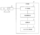
- FIG. 1 is a block diagram showing a schematic configuration of a measuring apparatus according to an embodiment of the present invention.
- FIG. 2 is a block diagram showing a specific configuration of the measuring apparatus according to the embodiment of the present invention.
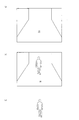
- FIG. 3 is a diagram illustrating an example of image data output from the depth sensor in the embodiment of the present invention.
- FIG. 3A illustrates a state in which no user is present on the walking path, and
- FIG. 3C indicates a difference.
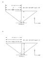
- 4A and 4B are diagrams for explaining the calculation processing of the three-dimensional coordinates in the embodiment of the present invention.
- FIG. 4A shows the horizontal direction of the screen
- FIG. 4B shows the vertical direction of the screen. Yes.
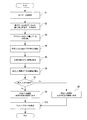
- FIG. 5 is a flowchart showing the operation of the measurement apparatus according to the embodiment of the present invention.
- FIG. 6 is a block diagram illustrating an example of a computer that implements the measurement apparatus according to the embodiment of the
- FIG. 1 is a block diagram showing a schematic configuration of a measuring apparatus according to an embodiment of the present invention.
- the measurement apparatus 10 includes a data acquisition unit 11, a specific pixel extraction unit 12, and a position calculation unit 13.
- the data acquisition unit 11 first acquires, from the depth sensor, image data (see FIG. 3A described later) in a state where no user is present on the walking path as reference data. Furthermore, the data acquisition unit 11 acquires, from the depth sensor, image data (see FIG. 3B described later) in a state where the user is walking on the walking path as walking data.
- the depth sensor is arranged so as to photograph a preset walking path and a space on the walking path. The depth sensor outputs image data to which a depth for each pixel is added.
- the specific pixel extraction unit 12 obtains a difference between the walking data and the reference data, and based on the obtained difference (see FIG. 3C described later) and the depth included in the difference, the foot located on the user's depth sensor side. Is identified. Further, the specific pixel extraction unit 12 extracts a pixel of the toe portion based on the depth from the pixels constituting the specified foot.
- the position calculation unit 13 calculates the three-dimensional coordinates of the pixel from the coordinates of the extracted pixel on the image data and the depth of the extracted pixel, and uses the calculated three-dimensional coordinate as the position of the user's toe. To do.
- the measurement device 10 can specify the position of the toe by using the image data to which the depth from the depth sensor is added. Therefore, according to the present embodiment, it is possible to measure the foot clearance using the depth sensor.
- FIG. 2 is a block diagram showing a specific configuration of the measuring apparatus according to the embodiment of the present invention.
- FIG. 3 is a diagram illustrating an example of image data output from the depth sensor in the embodiment of the present invention.
- FIG. 3A illustrates a state in which no user is present on the walking path
- FIG. 3C indicates a difference.
- the measuring device 10 is connected to a depth sensor 20.
- the measurement apparatus 10 receives image data to which the depth for each pixel is added from the depth sensor 20 by wire or wirelessly.
- the depth sensor 20 includes, for example, a light source that emits infrared laser light in a specific pattern and an image sensor that receives infrared light reflected by an object, and thereby image data to which a depth for each pixel is added. Is output.
- a specific example of the depth sensor is an existing depth sensor such as Kinect (registered trademark).
- the depth sensor 20 is arranged so that the walking path 30 and the space above it can be photographed.
- the walking path 30 is not particularly limited as long as it is a flat place where the user can walk.
- the measurement apparatus 10 includes a foot clearance calculation unit 14 in addition to the data acquisition unit 11, the specific pixel extraction unit 12, and the position calculation unit 13.
- the specific pixel extraction unit 12 is described as image data (hereinafter referred to as “difference image data”) that is the difference between the walking data and the reference data every time walking data is acquired.
- difference image data image data
- the user's limbs and a plurality of moving parts are specified.
- the specific pixel extraction unit 12 specifies the coordinates and depth on the image data for each specified part, and uses these to calculate the three-dimensional coordinates of each part.
- the three-dimensional coordinates are composed of the coordinates of the pixel on the image data and the depth added to the pixel.
- the specified parts are the head, neck, right shoulder, right elbow, right wrist, right thumb, right hand tip, left shoulder, left elbow, left wrist, left thumb, left hand tip, chest, waist, pelvis
- FIG. 4A and 4B are diagrams for explaining the calculation process of the three-dimensional coordinates in the embodiment of the present invention.
- FIG. 4A shows the XZ plane in the three-dimensional space
- FIG. 4B shows the three-dimensional space.
- the coordinates of a specific point on the image data to which the depth is added are (DX, DY), and the depth at the specific point is DPT.
- the number of pixels in the horizontal direction of the image data is 2CX, and the number of pixels in the vertical direction is 2CY.
- the horizontal viewing angle of the depth sensor is 2 ⁇ , and the vertical viewing angle is 2 ⁇ .
- the three-dimensional coordinates (WX, WY, WZ) of the specific point are calculated by the following equations 1 to 3, as can be seen from FIGS. 4 (a) and 4 (b).
- the specific pixel extraction unit 12 compares the depths of the right and left ankles using the three-dimensional coordinates of the positions of the left and right ankles, and determines the foot having the smaller value as the depth sensor side.
- the foot is specified as (Fig. 3 (a) and (b)).
- the specific pixel extraction unit 12 assumes that the middle of the line segment connecting the knee and the ankle in the three-dimensional space for the specified foot is a shin, and the third order of the ti Calculate original coordinates. Further, the specific pixel extraction unit 12 calculates coordinates on the image data of the shin from the calculated three-dimensional coordinates of the shin, and based on the calculated coordinates, among the pixels constituting the specified foot region From this, the part below the user's shin is extracted. Then, the specific pixel extraction unit 12 selects the pixel located closest to the pixel constituting the extracted portion, that is, the pixel having the smallest depth, based on the depth of each pixel constituting the extracted portion. Further extraction is performed, and the extracted pixel is used as a pixel in the toe portion.
- the position calculation unit 13 first calculates the coordinates on the original image data of the pixels extracted by the specific pixel extraction unit 12 as the toe portion pixels. Then, the position calculation unit 13 calculates the three-dimensional coordinates of the user's toe using the calculated coordinates on the image data and the extracted pixel depth.
- the foot clearance calculation unit 14 acquires the three-dimensional coordinates of the user's toes calculated by the position calculation unit 13 as needed, and every time the three-dimensional coordinates are acquired, the acquired three-dimensional coordinates and a pre-registered walking path
- the foot clearance is calculated by comparison with 30 three-dimensional coordinates. Specifically, the foot clearance is calculated, for example, by calculating a difference between vertical components of two three-dimensional coordinates.
- the calculated foot clearance is displayed, for example, on the screen of a display device connected to the measurement device 10 together with the determination result of the right foot and the left foot. As described above, according to the measuring apparatus 10, it is possible to measure the foot clearance with a simple system configuration.
- FIG. 5 is a flowchart showing the operation of the measuring apparatus 10 according to the embodiment of the present invention.
- FIGS. 1 to 4 will be referred to as appropriate.
- the measurement method is implemented by operating the measurement device 10. Therefore, the description of the measurement method in the present embodiment is replaced with the following description of the operation of the measurement apparatus 10.
- the data acquisition unit 11 acquires reference data from the depth sensor 20 in advance. Then, as shown in FIG. 3, when the depth sensor 20 takes a picture while the user is walking on the walking path 30, and the obtained image data is output, the data acquisition unit 12 outputs the walking data. Obtain (step S1).
- the specific pixel extraction unit 12 obtains image data (difference image data) that is a difference between the walking data acquired in step S1 and the reference data, and extracts the difference image data (step S2).
- the specific pixel extraction unit 12 specifies a plurality of parts of the user's limbs and moving objects in the difference image data extracted in step S2, and calculates three-dimensional coordinates of the specified parts. Then, the specific pixel extraction unit 12 compares the depth of the ankle of the right foot with the depth of the ankle of the left foot using the three-dimensional coordinates of the positions of the left and right foot ankles, and is located on the user's depth sensor side. A foot is specified (step S3).
- the specific pixel extraction unit 12 extracts a portion below the user's shin from the pixels constituting the foot specified in step S3 (step S4).
- the specific pixel extraction unit 12 further extracts a pixel having the smallest depth among the pixels constituting the extracted portion based on the depth of each pixel constituting the extracted portion (step S5).
- the extracted pixels correspond to the toe portion pixels.
- the position calculation unit 13 calculates the coordinates on the original image data of the pixel extracted in step S5, and based on the calculated coordinates on the image data and the pixel depth extracted in step S5. Then, the three-dimensional coordinates of the pixels extracted in step S5 are calculated (step S6). This calculated three-dimensional coordinate becomes the position of the user's toe.
- step S7 determines whether or not the foot specified in step S3 is the user's right foot. If the result of determination in step S7 is that the foot is a right foot, the position calculation unit 13 uses the coordinates calculated in step S6 as the coordinates of the toe of the right foot (step S8). On the other hand, if the result of determination in step S7 is not the right foot, the position calculation unit 13 sets the coordinates calculated in step S6 as the coordinates of the toe of the left foot (step S9).
- the foot clearance calculation unit 14 calculates the foot clearance by comparing the three-dimensional coordinates calculated in step S6 with the three-dimensional coordinates of the walking path 30 registered in advance (Ste S10). In step S ⁇ b> 10, the foot clearance calculation unit 14 displays the calculated foot clearance and the determination result of the right foot and the left foot on a screen of a display device connected to the measurement device 10.
- steps S1 to S10 are repeated every time the image is taken by the depth sensor 20 while the user is walking on the walking path 30, and the obtained image data is output, that is, every frame. Executed.
- the position of the toe can be specified and the foot clearance can be accurately measured only by photographing the user in the walking state by the depth sensor 20. And according to the measuring apparatus 10, since a simple system configuration is sufficient, the increase in the cost concerning the measurement of foot clearance is suppressed.
- the program in the present embodiment may be a program that causes a computer to execute steps S1 to S10 shown in FIG.
- a CPU Central Processing Unit
- the program in the present embodiment may be a program that causes a computer to execute steps S1 to S10 shown in FIG.
- each computer may function as any one of the data acquisition unit 11, the specific pixel extraction unit 12, the position calculation unit 13, the left / right determination unit 14, and the foot clearance calculation unit 14, respectively.
- FIG. 6 is a block diagram illustrating an example of a computer that implements the measurement apparatus according to the embodiment of the present invention.
- the computer 110 includes a CPU 111, a main memory 112, a storage device 113, an input interface 114, a display controller 115, a data reader / writer 116, and a communication interface 117. These units are connected to each other via a bus 121 so that data communication is possible.
- the CPU 111 performs various operations by developing the program (code) in the present embodiment stored in the storage device 113 in the main memory 112 and executing them in a predetermined order.
- the main memory 112 is typically a volatile storage device such as a DRAM (Dynamic Random Access Memory).
- the program in the present embodiment is provided in a state of being stored in a computer-readable recording medium 120. Note that the program in the present embodiment may be distributed on the Internet connected via the communication interface 117.
- the storage device 113 includes a hard disk drive and a semiconductor storage device such as a flash memory.
- the input interface 114 mediates data transmission between the CPU 111 and an input device 118 such as a keyboard and a mouse.
- the display controller 115 is connected to the display device 119 and controls display on the display device 119.
- the data reader / writer 116 mediates data transmission between the CPU 111 and the recording medium 120, and reads a program from the recording medium 120 and writes a processing result in the computer 110 to the recording medium 120.
- the communication interface 117 mediates data transmission between the CPU 111 and another computer.
- the recording medium 120 include general-purpose semiconductor storage devices such as CF (Compact Flash (registered trademark)) and SD (Secure Digital), magnetic storage media such as a flexible disk, or CD- Optical storage media such as ROM (Compact Disk Read Only Memory) are listed.
- CF Compact Flash
- SD Secure Digital
- magnetic storage media such as a flexible disk
- CD- Optical storage media such as ROM (Compact Disk Read Only Memory) are listed.
- the measuring apparatus 10 can be realized not by using a computer in which a program is installed but also by using hardware corresponding to each unit. Furthermore, the measurement apparatus 10 may be partially realized by a program and the remaining part may be realized by hardware.
- An apparatus for measuring the position of a toe of a walking user The user is not present in the walking path from a depth sensor that is arranged to photograph a preset walking path and a space on the walking path and outputs image data to which a depth for each pixel is added.
- a data acquisition unit that acquires image data of a state as reference data, and further acquires image data of a state in which the user is walking on the walking path as walking data; The difference between the walking data and the reference data is obtained, the foot located on the depth sensor side of the user is identified from the obtained difference and the depth included in the difference, and the identified foot is further configured.
- a specific pixel extracting unit that extracts pixels of the toe part based on the depth from among the pixels From the coordinates of the extracted pixel on the image data and the depth of the extracted pixel, the three-dimensional coordinate of the pixel is calculated, and the calculated three-dimensional coordinate is used as the position of the user's toe.
- a measuring device comprising:
- the position calculation unit determines whether the identified foot is the right foot or the left foot of the user, and calculates the position of the toe of the user as the position of the toe of the foot on the determined side. To The measuring device according to appendix 1.
- the specific pixel extraction unit extracts the pixel having the smallest depth from among the pixels constituting the specified foot, The measuring apparatus according to appendix 1 or 2.
- (Appendix 4) A method for measuring the position of a toe of a walking user, (A) The user is present in the walking path from a depth sensor that is arranged so as to capture a preset walking path and a space on the walking path and outputs image data to which a depth for each pixel is added.
- (Appendix 7) A computer-readable recording medium in which a program for measuring the position of a toe of a walking user is recorded by a computer, In the computer, (A) The user is present in the walking path from a depth sensor that is arranged so as to capture a preset walking path and a space on the walking path and outputs image data to which a depth for each pixel is added.
- the present invention it is possible to measure a foot clearance using a depth sensor.
- the present invention is useful in a field where grasping of the health condition of a user is required.
Landscapes
- Engineering & Computer Science (AREA)
- Health & Medical Sciences (AREA)
- Physics & Mathematics (AREA)
- Life Sciences & Earth Sciences (AREA)
- General Physics & Mathematics (AREA)
- Computer Vision & Pattern Recognition (AREA)
- Theoretical Computer Science (AREA)
- Pathology (AREA)
- Animal Behavior & Ethology (AREA)
- Biomedical Technology (AREA)
- Heart & Thoracic Surgery (AREA)
- Medical Informatics (AREA)
- Molecular Biology (AREA)
- Surgery (AREA)
- Physiology (AREA)
- General Health & Medical Sciences (AREA)
- Public Health (AREA)
- Veterinary Medicine (AREA)
- Biophysics (AREA)
- Oral & Maxillofacial Surgery (AREA)
- Multimedia (AREA)
- Dentistry (AREA)
- Nuclear Medicine, Radiotherapy & Molecular Imaging (AREA)
- Radiology & Medical Imaging (AREA)
- Human Computer Interaction (AREA)
- Measurement Of The Respiration, Hearing Ability, Form, And Blood Characteristics Of Living Organisms (AREA)
- Length Measuring Devices By Optical Means (AREA)
- Image Analysis (AREA)
- Image Processing (AREA)
Abstract
Description
予め設定された歩行路及び前記歩行路上の空間を撮影するように配置され、且つ、画素毎の深度が付加された画像データを出力する、デプスセンサから、前記歩行路に前記ユーザが存在していない状態の画像データを基準データとして取得し、更に、前記歩行路を前記ユーザが歩行している状態の画像データを、歩行データとして取得する、データ取得部と、
前記歩行データと前記基準データとの差分を求め、求めた差分と前記差分に含まれる深度とから、前記ユーザの前記デプスセンサ側に位置している足を特定し、更に、特定した足を構成している画素の中から、前記深度に基づいて爪先部分の画素を抽出する、特定画素抽出部と、
抽出された前記画素の前記画像データ上での座標と、抽出された前記画素の前記深度とから、前記画素の三次元座標を算出し、算出した前記三次元座標を前記ユーザの爪先の位置とする、位置算出部と、
を備えていることを特徴とする。
(a)予め設定された歩行路及び前記歩行路上の空間を撮影するように配置され、且つ、画素毎の深度が付加された画像データを出力する、デプスセンサから、前記歩行路に前記ユーザが存在していない状態の画像データを基準データとして取得し、更に、前記歩行路を前記ユーザが歩行している状態の画像データを、歩行データとして取得する、ステップと、
(b)前記歩行データと前記基準データとの差分を求め、求めた差分と前記差分に含まれる深度とから、前記ユーザの前記デプスセンサ側に位置している足を特定し、更に、特定した足を構成している画素の中から、前記深度に基づいて爪先部分の画素を抽出する、ステップと、
(c)抽出された前記画素の前記画像データ上での座標と、抽出された前記画素の前記深度とから、前記画素の三次元座標を算出し、算出した前記三次元座標を前記ユーザの爪先の位置とする、ステップと、
を有することを特徴とする。
前記コンピュータに、
(a)予め設定された歩行路及び前記歩行路上の空間を撮影するように配置され、且つ、画素毎の深度が付加された画像データを出力する、デプスセンサから、前記歩行路に前記ユーザが存在していない状態の画像データを基準データとして取得し、更に、前記歩行路を前記ユーザが歩行している状態の画像データを、歩行データとして取得する、ステップと、
(b)前記歩行データと前記基準データとの差分を求め、求めた差分と前記差分に含まれる深度とから、前記ユーザの前記デプスセンサ側に位置している足を特定し、更に、特定した足を構成している画素の中から、前記深度に基づいて爪先部分の画素を抽出する、ステップと、
(c)抽出された前記画素の前記画像データ上での座標と、抽出された前記画素の前記深度とから、前記画素の三次元座標を算出し、算出した前記三次元座標を前記ユーザの爪先の位置とする、ステップと、
を実行させる、命令を含むプログラムを記録していることを特徴とする。
以下、本発明の実施の形態における、計測装置、計測方法、及びプログラムについて、図1~図5を参照しながら説明する。
最初に、本実施の形態における計測装置の概略構成について図1を用いて説明する。図1は、本発明の実施の形態における計測装置の概略構成を示すブロック図である。
WX=((CX-DX)×DPT×tanθ)/CX
WY=((CY-DY)×DPT×tanφ)/CY
WZ=DPT
次に、本発明の実施の形態における計測装置10の動作について図5を用いて説明する。図5は、本発明の実施の形態における計測装置10の動作を示すフロー図である。以下の説明においては、適宜図1~図4を参照する。また、本実施の形態では、計測装置10を動作させることによって、計測方法が実施される。よって、本実施の形態における計測方法の説明は、以下の計測装置10の動作説明に代える。
このように、計測装置10によれば、デプスセンサ20によって、歩行状態のユーザを撮影するだけで、爪先の位置を特定でき、正確にフットクリアランスを測定できる。そして、計測装置10によれば、簡単なシステム構成で良いため、フットクリアランスの測定にかかるコストの増加が抑制される。
本実施の形態におけるプログラムは、コンピュータに、図5に示すステップS1~S10を実行させるプログラムであれば良い。このプログラムをコンピュータにインストールし、実行することによって、本実施の形態における計測装置10と計測方法とを実現することができる。この場合、コンピュータのCPU(Central Processing Unit)は、データ取得部11、特定画素抽出部12、位置算出部13、左右判定部14、及びフットクリアランス算出部14として機能し、処理を行なう。
歩行するユーザの爪先の位置を計測するための装置であって、
予め設定された歩行路及び前記歩行路上の空間を撮影するように配置され、且つ、画素毎の深度が付加された画像データを出力する、デプスセンサから、前記歩行路に前記ユーザが存在していない状態の画像データを基準データとして取得し、更に、前記歩行路を前記ユーザが歩行している状態の画像データを、歩行データとして取得する、データ取得部と、
前記歩行データと前記基準データとの差分を求め、求めた差分と前記差分に含まれる深度とから、前記ユーザの前記デプスセンサ側に位置している足を特定し、更に、特定した足を構成している画素の中から、前記深度に基づいて爪先部分の画素を抽出する、特定画素抽出部と、
抽出された前記画素の前記画像データ上での座標と、抽出された前記画素の前記深度とから、前記画素の三次元座標を算出し、算出した前記三次元座標を前記ユーザの爪先の位置とする、位置算出部と、
を備えていることを特徴とする計測装置。
前記位置算出部は、特定された前記足が、前記ユーザの右足及び左足のいずれであるかを判定し、算出された前記ユーザの爪先の位置を、判定された側の足の爪先の位置とする、
付記1に記載の計測装置。
前記特定画素抽出部が、特定した足を構成している画素のうち、前記深度が最も小さい画素を抽出する、
付記1または2に記載の計測装置。
歩行するユーザの爪先の位置を計測するための方法であって、
(a)予め設定された歩行路及び前記歩行路上の空間を撮影するように配置され、且つ、画素毎の深度が付加された画像データを出力する、デプスセンサから、前記歩行路に前記ユーザが存在していない状態の画像データを基準データとして取得し、更に、前記歩行路を前記ユーザが歩行している状態の画像データを、歩行データとして取得する、ステップと、
(b)前記歩行データと前記基準データとの差分を求め、求めた差分と前記差分に含まれる深度とから、前記ユーザの前記デプスセンサ側に位置している足を特定し、更に、特定した足を構成している画素の中から、前記深度に基づいて爪先部分の画素を抽出する、ステップと、
(c)抽出された前記画素の前記画像データ上での座標と、抽出された前記画素の前記深度とから、前記画素の三次元座標を算出し、算出した前記三次元座標を前記ユーザの爪先の位置とする、ステップと、
を有することを特徴とする計測方法。
(d)特定された前記足が、前記ユーザの右足及び左足のいずれであるかを判定し、算出された前記ユーザの爪先の位置を、判定された側の足の爪先の位置とする、ステップを更に有している、付記4に記載の計測方法。
前記(b)のステップにおいて、特定した足を構成している画素のうち、前記深度が最も小さい画素を抽出する、
付記4または5に記載の計測方法。
コンピュータによって、歩行するユーザの爪先の位置を計測するためのプログラムを記録したコンピュータ読み取り可能な記録媒体であって、
前記コンピュータに、
(a)予め設定された歩行路及び前記歩行路上の空間を撮影するように配置され、且つ、画素毎の深度が付加された画像データを出力する、デプスセンサから、前記歩行路に前記ユーザが存在していない状態の画像データを基準データとして取得し、更に、前記歩行路を前記ユーザが歩行している状態の画像データを、歩行データとして取得する、ステップと、
(b)前記歩行データと前記基準データとの差分を求め、求めた差分と前記差分に含まれる深度とから、前記ユーザの前記デプスセンサ側に位置している足を特定し、更に、特定した足を構成している画素の中から、前記深度に基づいて爪先部分の画素を抽出する、ステップと、
(c)抽出された前記画素の前記画像データ上での座標と、抽出された前記画素の前記深度とから、前記画素の三次元座標を算出し、算出した前記三次元座標を前記ユーザの爪先の位置とする、ステップと、
を実行させる命令を含む、プログラムを記録しているコンピュータ読み取り可能な記録媒体。
前記コンピュータに、
(d)特定された前記足が、前記ユーザの右足及び左足のいずれであるかを判定し、算出された前記ユーザの爪先の位置を、判定された側の足の爪先の位置とする、ステップを更に実行させる、付記7に記載のコンピュータ読み取り可能な記録媒体。
前記(b)のステップにおいて、特定した足を構成している画素のうち、前記深度が最も小さい画素を抽出する、
付記7または8に記載のコンピュータ読み取り可能な記録媒体。
11 データ取得部
12 特定画素抽出部
13 位置算出部
14 フットクリアランス算出部
20 デプスセンサ
30 歩行路
111 CPU
112 メインメモリ
113 記憶装置
114 入力インターフェイス
115 表示コントローラ
116 データリーダ/ライタ
117 通信インターフェイス
118 入力機器
119 ディスプレイ装置
120 記録媒体
121 バス
Claims (9)
- 歩行するユーザの爪先の位置を計測するための装置であって、
予め設定された歩行路及び前記歩行路上の空間を撮影するように配置され、且つ、画素毎の深度が付加された画像データを出力する、デプスセンサから、前記歩行路に前記ユーザが存在していない状態の画像データを基準データとして取得し、更に、前記歩行路を前記ユーザが歩行している状態の画像データを、歩行データとして取得する、データ取得部と、
前記歩行データと前記基準データとの差分を求め、求めた差分と前記差分に含まれる深度とから、前記ユーザの前記デプスセンサ側に位置している足を特定し、更に、特定した足を構成している画素の中から、前記深度に基づいて爪先部分の画素を抽出する、特定画素抽出部と、
抽出された前記画素の前記画像データ上での座標と、抽出された前記画素の前記深度とから、前記画素の三次元座標を算出し、算出した前記三次元座標を前記ユーザの爪先の位置とする、位置算出部と、
を備えていることを特徴とする計測装置。 - 前記位置算出部は、特定された前記足が、前記ユーザの右足及び左足のいずれであるかを判定し、算出された前記ユーザの爪先の位置を、判定された側の足の爪先の位置とする、
請求項1に記載の計測装置。 - 前記特定画素抽出部が、特定した足を構成している画素のうち、前記深度が最も小さい画素を抽出する、
請求項1または2に記載の計測装置。 - 歩行するユーザの爪先の位置を計測するための方法であって、
(a)予め設定された歩行路及び前記歩行路上の空間を撮影するように配置され、且つ、画素毎の深度が付加された画像データを出力する、デプスセンサから、前記歩行路に前記ユーザが存在していない状態の画像データを基準データとして取得し、更に、前記歩行路を前記ユーザが歩行している状態の画像データを、歩行データとして取得する、ステップと、
(b)前記歩行データと前記基準データとの差分を求め、求めた差分と前記差分に含まれる深度とから、前記ユーザの前記デプスセンサ側に位置している足を特定し、更に、特定した足を構成している画素の中から、前記深度に基づいて爪先部分の画素を抽出する、ステップと、
(c)抽出された前記画素の前記画像データ上での座標と、抽出された前記画素の前記深度とから、前記画素の三次元座標を算出し、算出した前記三次元座標を前記ユーザの爪先の位置とする、ステップと、
を有することを特徴とする計測方法。 - (d)特定された前記足が、前記ユーザの右足及び左足のいずれであるかを判定し、算出された前記ユーザの爪先の位置を、判定された側の足の爪先の位置とする、ステップを更に有している、請求項4に記載の計測方法。
- 前記(b)のステップにおいて、特定した足を構成している画素のうち、前記深度が最も小さい画素を抽出する、
請求項4または5に記載の計測方法。 - コンピュータによって、歩行するユーザの爪先の位置を計測するためのプログラムを記録したコンピュータ読み取り可能な記録媒体であって、
前記コンピュータに、
(a)予め設定された歩行路及び前記歩行路上の空間を撮影するように配置され、且つ、画素毎の深度が付加された画像データを出力する、デプスセンサから、前記歩行路に前記ユーザが存在していない状態の画像データを基準データとして取得し、更に、前記歩行路を前記ユーザが歩行している状態の画像データを、歩行データとして取得する、ステップと、
(b)前記歩行データと前記基準データとの差分を求め、求めた差分と前記差分に含まれる深度とから、前記ユーザの前記デプスセンサ側に位置している足を特定し、更に、特定した足を構成している画素の中から、前記深度に基づいて爪先部分の画素を抽出する、ステップと、
(c)抽出された前記画素の前記画像データ上での座標と、抽出された前記画素の前記深度とから、前記画素の三次元座標を算出し、算出した前記三次元座標を前記ユーザの爪先の位置とする、ステップと、
を実行させる命令を含む、プログラムを記録しているコンピュータ読み取り可能な記録媒体。 - 前記コンピュータに、
(d)特定された前記足が、前記ユーザの右足及び左足のいずれであるかを判定し、算出された前記ユーザの爪先の位置を、判定された側の足の爪先の位置とする、ステップを更に実行させる、請求項7に記載のコンピュータ読み取り可能な記録媒体。 - 前記(b)のステップにおいて、特定した足を構成している画素のうち、前記深度が最も小さい画素を抽出する、
請求項7または8に記載のコンピュータ読み取り可能な記録媒体。
Priority Applications (4)
| Application Number | Priority Date | Filing Date | Title |
|---|---|---|---|
| EP17774977.7A EP3438601B1 (en) | 2016-03-28 | 2017-03-27 | Measurement device, measurement method, and computer program |
| JP2018508010A JP6558820B2 (ja) | 2016-03-28 | 2017-03-27 | 計測装置、計測方法、及びプログラム |
| CN201780017273.9A CN108885087B (zh) | 2016-03-28 | 2017-03-27 | 测量装置、测量方法和计算机可读记录介质 |
| US16/084,497 US10796449B2 (en) | 2016-03-28 | 2017-03-27 | Measurement device, measurement method, and computer readable recording medium |
Applications Claiming Priority (2)
| Application Number | Priority Date | Filing Date | Title |
|---|---|---|---|
| JP2016-064212 | 2016-03-28 | ||
| JP2016064212 | 2016-03-28 |
Publications (1)
| Publication Number | Publication Date |
|---|---|
| WO2017170440A1 true WO2017170440A1 (ja) | 2017-10-05 |
Family
ID=59964597
Family Applications (1)
| Application Number | Title | Priority Date | Filing Date |
|---|---|---|---|
| PCT/JP2017/012462 Ceased WO2017170440A1 (ja) | 2016-03-28 | 2017-03-27 | 計測装置、計測方法、及びコンピュータ読み取り可能な記録媒体 |
Country Status (5)
| Country | Link |
|---|---|
| US (1) | US10796449B2 (ja) |
| EP (1) | EP3438601B1 (ja) |
| JP (1) | JP6558820B2 (ja) |
| CN (1) | CN108885087B (ja) |
| WO (1) | WO2017170440A1 (ja) |
Cited By (2)
| Publication number | Priority date | Publication date | Assignee | Title |
|---|---|---|---|---|
| CN112764546A (zh) * | 2021-01-29 | 2021-05-07 | 重庆子元科技有限公司 | 一种虚拟人物位移控制方法、装置及终端设备 |
| JP2024084756A (ja) * | 2017-12-26 | 2024-06-25 | パナソニックIpマネジメント株式会社 | 車両監視方法、車両監視装置、車両、及び車両監視システム |
Families Citing this family (4)
| Publication number | Priority date | Publication date | Assignee | Title |
|---|---|---|---|---|
| JP7669675B2 (ja) * | 2020-12-03 | 2025-04-30 | セイコーエプソン株式会社 | 特定方法、投写方法、特定システム、情報処理装置、及びプログラム |
| CN117136377A (zh) * | 2021-03-29 | 2023-11-28 | 日本电气方案创新株式会社 | 计算装置 |
| CN116664869A (zh) * | 2023-06-02 | 2023-08-29 | 齐鲁空天信息研究院 | 富能传感器的数据采集方法、装置、设备及介质 |
| CN117100250B (zh) * | 2023-07-10 | 2024-05-28 | 北京华益精点生物技术有限公司 | 脚趾位置的确定方法、装置、电子设备及存储介质 |
Citations (4)
| Publication number | Priority date | Publication date | Assignee | Title |
|---|---|---|---|---|
| JP2004028635A (ja) * | 2002-06-21 | 2004-01-29 | Hamamatsu Photonics Kk | 歩幅測定装置及び歩幅測定方法 |
| US20120130280A1 (en) * | 2010-11-18 | 2012-05-24 | Industry-Academic Cooperation Foundation, Kyungpook National University | Legs rehabilitation device and legs rehabilitation method using the same |
| JP2015042241A (ja) * | 2013-01-18 | 2015-03-05 | 株式会社東芝 | 動作情報処理装置及び方法 |
| JP2015061211A (ja) * | 2013-09-19 | 2015-03-30 | 富士ゼロックス株式会社 | 処理装置 |
Family Cites Families (15)
| Publication number | Priority date | Publication date | Assignee | Title |
|---|---|---|---|---|
| CN1265763C (zh) * | 2004-03-16 | 2006-07-26 | 中国科学院合肥智能机械研究所 | 一种多轴力平台阵列及人体行走步态信息获取方法 |
| CN101515374B (zh) | 2008-02-20 | 2010-12-01 | 中国科学院自动化研究所 | 基于图像的个性化真实感虚拟人物造型方法 |
| CN101650776B (zh) | 2008-08-12 | 2013-03-20 | 财团法人工业技术研究院 | 追踪人物肢体位置的方法与系统 |
| CN102971766B (zh) | 2010-06-30 | 2016-06-29 | 日本电气方案创新株式会社 | 头部检测方法、头部检测装置、属性判定方法、属性判定装置和属性判定系统 |
| CN102178530A (zh) | 2011-01-24 | 2011-09-14 | 天津大学 | 基于三维点云数据的人体尺寸自动测量方法 |
| US9974466B2 (en) | 2011-10-17 | 2018-05-22 | Atlas5D, Inc. | Method and apparatus for detecting change in health status |
| US20140045593A1 (en) | 2012-08-07 | 2014-02-13 | Microsoft Corporation | Virtual joint orientation in virtual skeleton |
| GB2509783B (en) * | 2013-01-15 | 2017-07-05 | Holition Ltd | Foot tracking |
| CN103971409B (zh) * | 2014-05-22 | 2017-01-11 | 福州大学 | 一种利用rgb-d摄像机测量足部三维脚型信息及三维重建模型的方法 |
| KR101606768B1 (ko) | 2014-06-24 | 2016-03-28 | (주)이튜 | 모션 추출기반의 보행 자세 교정장치 |
| JP2017205134A (ja) | 2014-08-25 | 2017-11-24 | ノーリツプレシジョン株式会社 | 体調検出装置、体調検出方法及び体調検出プログラム |
| CN104274179B (zh) | 2014-09-05 | 2017-04-19 | 深圳市职业病防治院 | 一种下肢功能测试指标的测试方法、装置及系统 |
| CN109152555B (zh) * | 2016-03-18 | 2022-09-06 | 哈佛大学校长及研究员协会 | 自动分类动物行为 |
| US10956723B2 (en) * | 2016-06-03 | 2021-03-23 | Pillar Vision, Inc. | Systems and methods for determining reduced player performance in sporting events |
| CN110494900A (zh) * | 2017-02-07 | 2019-11-22 | 韦奥机器人股份有限公司 | 工作空间安全监控和设备控制 |
-
2017
- 2017-03-27 CN CN201780017273.9A patent/CN108885087B/zh active Active
- 2017-03-27 JP JP2018508010A patent/JP6558820B2/ja active Active
- 2017-03-27 WO PCT/JP2017/012462 patent/WO2017170440A1/ja not_active Ceased
- 2017-03-27 EP EP17774977.7A patent/EP3438601B1/en active Active
- 2017-03-27 US US16/084,497 patent/US10796449B2/en active Active
Patent Citations (4)
| Publication number | Priority date | Publication date | Assignee | Title |
|---|---|---|---|---|
| JP2004028635A (ja) * | 2002-06-21 | 2004-01-29 | Hamamatsu Photonics Kk | 歩幅測定装置及び歩幅測定方法 |
| US20120130280A1 (en) * | 2010-11-18 | 2012-05-24 | Industry-Academic Cooperation Foundation, Kyungpook National University | Legs rehabilitation device and legs rehabilitation method using the same |
| JP2015042241A (ja) * | 2013-01-18 | 2015-03-05 | 株式会社東芝 | 動作情報処理装置及び方法 |
| JP2015061211A (ja) * | 2013-09-19 | 2015-03-30 | 富士ゼロックス株式会社 | 処理装置 |
Non-Patent Citations (1)
| Title |
|---|
| See also references of EP3438601A4 * |
Cited By (3)
| Publication number | Priority date | Publication date | Assignee | Title |
|---|---|---|---|---|
| JP2024084756A (ja) * | 2017-12-26 | 2024-06-25 | パナソニックIpマネジメント株式会社 | 車両監視方法、車両監視装置、車両、及び車両監視システム |
| CN112764546A (zh) * | 2021-01-29 | 2021-05-07 | 重庆子元科技有限公司 | 一种虚拟人物位移控制方法、装置及终端设备 |
| CN112764546B (zh) * | 2021-01-29 | 2022-08-09 | 重庆子元科技有限公司 | 一种虚拟人物位移控制方法、装置及终端设备 |
Also Published As
| Publication number | Publication date |
|---|---|
| US20190080472A1 (en) | 2019-03-14 |
| CN108885087B (zh) | 2020-05-26 |
| EP3438601B1 (en) | 2023-05-03 |
| EP3438601A4 (en) | 2019-11-20 |
| JP6558820B2 (ja) | 2019-08-14 |
| JPWO2017170440A1 (ja) | 2019-01-24 |
| EP3438601A1 (en) | 2019-02-06 |
| CN108885087A (zh) | 2018-11-23 |
| US10796449B2 (en) | 2020-10-06 |
Similar Documents
| Publication | Publication Date | Title |
|---|---|---|
| JP6558820B2 (ja) | 計測装置、計測方法、及びプログラム | |
| JP6662532B2 (ja) | 歩行分析装置、歩行分析方法、及びプログラム | |
| JP6334925B2 (ja) | 動作情報処理装置及び方法 | |
| JP6930995B2 (ja) | 立体画像生成システム、立体画像生成方法及び立体画像生成プログラム | |
| JP6188332B2 (ja) | 医用画像表示装置及びプログラム | |
| KR101118654B1 (ko) | 모션캡쳐 기반의 자세분석을 통한 재활 장치 및 이에 따른 재활 방법 | |
| WO2014112635A1 (ja) | 動作情報処理装置 | |
| WO2017222072A1 (ja) | 姿勢分析装置、姿勢分析方法、及びコンピュータ読み取り可能な記録媒体 | |
| JP2017205134A (ja) | 体調検出装置、体調検出方法及び体調検出プログラム | |
| JP6940139B2 (ja) | 身体特性分析装置、身体特性分析方法、及びプログラム | |
| Samad et al. | Elbow Flexion and Extension Rehabilitation Exercise System Using Marker-less Kinect-based Method. | |
| KR102310964B1 (ko) | 근골격계 증상을 진단하기 위한 전자 장치, 방법, 및 시스템 | |
| US20220058830A1 (en) | Information processing apparatus, information processing method, and program | |
| Rana | Leveraging Markerless Computer Vision for Comprehensive Walking Automated Gait Analysis in Rehabilitation | |
| KR20140013662A (ko) | 캘리브레이션 장치 및 방법 | |
| JP7494692B2 (ja) | 深度推定方法 | |
| US20250107750A1 (en) | Posture evaluation apparatus, posture evaluation system, posture evaluation method, and computer readable medium | |
| Alothmany et al. | Accuracy of joint angles tracking using markerless motion system | |
| JP2025008381A (ja) | 評価システム、および、プログラム | |
| WO2025107029A1 (en) | Systems, methods and devices for monitoring gait | |
| JPWO2016208289A1 (ja) | 測定装置及び測定方法 |
Legal Events
| Date | Code | Title | Description |
|---|---|---|---|
| WWE | Wipo information: entry into national phase |
Ref document number: 2018508010 Country of ref document: JP |
|
| NENP | Non-entry into the national phase |
Ref country code: DE |
|
| WWE | Wipo information: entry into national phase |
Ref document number: 2017774977 Country of ref document: EP |
|
| ENP | Entry into the national phase |
Ref document number: 2017774977 Country of ref document: EP Effective date: 20181029 |
|
| 121 | Ep: the epo has been informed by wipo that ep was designated in this application |
Ref document number: 17774977 Country of ref document: EP Kind code of ref document: A1 |