WO2017170441A1 - 電動機ユニット - Google Patents
電動機ユニット Download PDFInfo
- Publication number
- WO2017170441A1 WO2017170441A1 PCT/JP2017/012464 JP2017012464W WO2017170441A1 WO 2017170441 A1 WO2017170441 A1 WO 2017170441A1 JP 2017012464 W JP2017012464 W JP 2017012464W WO 2017170441 A1 WO2017170441 A1 WO 2017170441A1
- Authority
- WO
- WIPO (PCT)
- Prior art keywords
- electric motor
- motor
- stator
- reference position
- resolver
- Prior art date
- Legal status (The legal status is an assumption and is not a legal conclusion. Google has not performed a legal analysis and makes no representation as to the accuracy of the status listed.)
- Ceased
Links
Images




Classifications
-
- B—PERFORMING OPERATIONS; TRANSPORTING
- B60—VEHICLES IN GENERAL
- B60K—ARRANGEMENT OR MOUNTING OF PROPULSION UNITS OR OF TRANSMISSIONS IN VEHICLES; ARRANGEMENT OR MOUNTING OF PLURAL DIVERSE PRIME-MOVERS IN VEHICLES; AUXILIARY DRIVES FOR VEHICLES; INSTRUMENTATION OR DASHBOARDS FOR VEHICLES; ARRANGEMENTS IN CONNECTION WITH COOLING, AIR INTAKE, GAS EXHAUST OR FUEL SUPPLY OF PROPULSION UNITS IN VEHICLES
- B60K6/00—Arrangement or mounting of plural diverse prime-movers for mutual or common propulsion, e.g. hybrid propulsion systems comprising electric motors and internal combustion engines
- B60K6/20—Arrangement or mounting of plural diverse prime-movers for mutual or common propulsion, e.g. hybrid propulsion systems comprising electric motors and internal combustion engines the prime-movers consisting of electric motors and internal combustion engines, e.g. HEVs
- B60K6/50—Architecture of the driveline characterised by arrangement or kind of transmission units
- B60K6/52—Driving a plurality of drive axles, e.g. four-wheel drive
-
- H—ELECTRICITY
- H02—GENERATION; CONVERSION OR DISTRIBUTION OF ELECTRIC POWER
- H02K—DYNAMO-ELECTRIC MACHINES
- H02K24/00—Machines adapted for the instantaneous transmission or reception of the angular displacement of rotating parts, e.g. synchro, selsyn
-
- B—PERFORMING OPERATIONS; TRANSPORTING
- B60—VEHICLES IN GENERAL
- B60K—ARRANGEMENT OR MOUNTING OF PROPULSION UNITS OR OF TRANSMISSIONS IN VEHICLES; ARRANGEMENT OR MOUNTING OF PLURAL DIVERSE PRIME-MOVERS IN VEHICLES; AUXILIARY DRIVES FOR VEHICLES; INSTRUMENTATION OR DASHBOARDS FOR VEHICLES; ARRANGEMENTS IN CONNECTION WITH COOLING, AIR INTAKE, GAS EXHAUST OR FUEL SUPPLY OF PROPULSION UNITS IN VEHICLES
- B60K1/00—Arrangement or mounting of electrical propulsion units
- B60K1/02—Arrangement or mounting of electrical propulsion units comprising more than one electric motor
-
- B—PERFORMING OPERATIONS; TRANSPORTING
- B60—VEHICLES IN GENERAL
- B60K—ARRANGEMENT OR MOUNTING OF PROPULSION UNITS OR OF TRANSMISSIONS IN VEHICLES; ARRANGEMENT OR MOUNTING OF PLURAL DIVERSE PRIME-MOVERS IN VEHICLES; AUXILIARY DRIVES FOR VEHICLES; INSTRUMENTATION OR DASHBOARDS FOR VEHICLES; ARRANGEMENTS IN CONNECTION WITH COOLING, AIR INTAKE, GAS EXHAUST OR FUEL SUPPLY OF PROPULSION UNITS IN VEHICLES
- B60K17/00—Arrangement or mounting of transmissions in vehicles
- B60K17/04—Arrangement or mounting of transmissions in vehicles characterised by arrangement, location or kind of gearing
- B60K17/043—Transmission unit disposed in on near the vehicle wheel, or between the differential gear unit and the wheel
- B60K17/046—Transmission unit disposed in on near the vehicle wheel, or between the differential gear unit and the wheel with planetary gearing having orbital motion
-
- B—PERFORMING OPERATIONS; TRANSPORTING
- B60—VEHICLES IN GENERAL
- B60K—ARRANGEMENT OR MOUNTING OF PROPULSION UNITS OR OF TRANSMISSIONS IN VEHICLES; ARRANGEMENT OR MOUNTING OF PLURAL DIVERSE PRIME-MOVERS IN VEHICLES; AUXILIARY DRIVES FOR VEHICLES; INSTRUMENTATION OR DASHBOARDS FOR VEHICLES; ARRANGEMENTS IN CONNECTION WITH COOLING, AIR INTAKE, GAS EXHAUST OR FUEL SUPPLY OF PROPULSION UNITS IN VEHICLES
- B60K6/00—Arrangement or mounting of plural diverse prime-movers for mutual or common propulsion, e.g. hybrid propulsion systems comprising electric motors and internal combustion engines
- B60K6/20—Arrangement or mounting of plural diverse prime-movers for mutual or common propulsion, e.g. hybrid propulsion systems comprising electric motors and internal combustion engines the prime-movers consisting of electric motors and internal combustion engines, e.g. HEVs
- B60K6/22—Arrangement or mounting of plural diverse prime-movers for mutual or common propulsion, e.g. hybrid propulsion systems comprising electric motors and internal combustion engines the prime-movers consisting of electric motors and internal combustion engines, e.g. HEVs characterised by apparatus, components or means specially adapted for HEVs
- B60K6/36—Arrangement or mounting of plural diverse prime-movers for mutual or common propulsion, e.g. hybrid propulsion systems comprising electric motors and internal combustion engines the prime-movers consisting of electric motors and internal combustion engines, e.g. HEVs characterised by apparatus, components or means specially adapted for HEVs characterised by the transmission gearings
-
- B—PERFORMING OPERATIONS; TRANSPORTING
- B60—VEHICLES IN GENERAL
- B60K—ARRANGEMENT OR MOUNTING OF PROPULSION UNITS OR OF TRANSMISSIONS IN VEHICLES; ARRANGEMENT OR MOUNTING OF PLURAL DIVERSE PRIME-MOVERS IN VEHICLES; AUXILIARY DRIVES FOR VEHICLES; INSTRUMENTATION OR DASHBOARDS FOR VEHICLES; ARRANGEMENTS IN CONNECTION WITH COOLING, AIR INTAKE, GAS EXHAUST OR FUEL SUPPLY OF PROPULSION UNITS IN VEHICLES
- B60K6/00—Arrangement or mounting of plural diverse prime-movers for mutual or common propulsion, e.g. hybrid propulsion systems comprising electric motors and internal combustion engines
- B60K6/20—Arrangement or mounting of plural diverse prime-movers for mutual or common propulsion, e.g. hybrid propulsion systems comprising electric motors and internal combustion engines the prime-movers consisting of electric motors and internal combustion engines, e.g. HEVs
- B60K6/42—Arrangement or mounting of plural diverse prime-movers for mutual or common propulsion, e.g. hybrid propulsion systems comprising electric motors and internal combustion engines the prime-movers consisting of electric motors and internal combustion engines, e.g. HEVs characterised by the architecture of the hybrid electric vehicle
- B60K6/44—Series-parallel type
- B60K6/448—Electrical distribution type
-
- B—PERFORMING OPERATIONS; TRANSPORTING
- B60—VEHICLES IN GENERAL
- B60K—ARRANGEMENT OR MOUNTING OF PROPULSION UNITS OR OF TRANSMISSIONS IN VEHICLES; ARRANGEMENT OR MOUNTING OF PLURAL DIVERSE PRIME-MOVERS IN VEHICLES; AUXILIARY DRIVES FOR VEHICLES; INSTRUMENTATION OR DASHBOARDS FOR VEHICLES; ARRANGEMENTS IN CONNECTION WITH COOLING, AIR INTAKE, GAS EXHAUST OR FUEL SUPPLY OF PROPULSION UNITS IN VEHICLES
- B60K6/00—Arrangement or mounting of plural diverse prime-movers for mutual or common propulsion, e.g. hybrid propulsion systems comprising electric motors and internal combustion engines
- B60K6/20—Arrangement or mounting of plural diverse prime-movers for mutual or common propulsion, e.g. hybrid propulsion systems comprising electric motors and internal combustion engines the prime-movers consisting of electric motors and internal combustion engines, e.g. HEVs
- B60K6/50—Architecture of the driveline characterised by arrangement or kind of transmission units
- B60K6/54—Transmission for changing ratio
-
- B—PERFORMING OPERATIONS; TRANSPORTING
- B60—VEHICLES IN GENERAL
- B60K—ARRANGEMENT OR MOUNTING OF PROPULSION UNITS OR OF TRANSMISSIONS IN VEHICLES; ARRANGEMENT OR MOUNTING OF PLURAL DIVERSE PRIME-MOVERS IN VEHICLES; AUXILIARY DRIVES FOR VEHICLES; INSTRUMENTATION OR DASHBOARDS FOR VEHICLES; ARRANGEMENTS IN CONNECTION WITH COOLING, AIR INTAKE, GAS EXHAUST OR FUEL SUPPLY OF PROPULSION UNITS IN VEHICLES
- B60K7/00—Disposition of motor in, or adjacent to, traction wheel
- B60K7/0007—Disposition of motor in, or adjacent to, traction wheel the motor being electric
-
- B—PERFORMING OPERATIONS; TRANSPORTING
- B60—VEHICLES IN GENERAL
- B60W—CONJOINT CONTROL OF VEHICLE SUB-UNITS OF DIFFERENT TYPE OR DIFFERENT FUNCTION; CONTROL SYSTEMS SPECIALLY ADAPTED FOR HYBRID VEHICLES; ROAD VEHICLE DRIVE CONTROL SYSTEMS FOR PURPOSES NOT RELATED TO THE CONTROL OF A PARTICULAR SUB-UNIT
- B60W20/00—Control systems specially adapted for hybrid vehicles
-
- H—ELECTRICITY
- H02—GENERATION; CONVERSION OR DISTRIBUTION OF ELECTRIC POWER
- H02K—DYNAMO-ELECTRIC MACHINES
- H02K11/00—Structural association of dynamo-electric machines with electric components or with devices for shielding, monitoring or protection
- H02K11/20—Structural association of dynamo-electric machines with electric components or with devices for shielding, monitoring or protection for measuring, monitoring, testing, protecting or switching
- H02K11/21—Devices for sensing speed or position, or actuated thereby
-
- H—ELECTRICITY
- H02—GENERATION; CONVERSION OR DISTRIBUTION OF ELECTRIC POWER
- H02K—DYNAMO-ELECTRIC MACHINES
- H02K11/00—Structural association of dynamo-electric machines with electric components or with devices for shielding, monitoring or protection
- H02K11/20—Structural association of dynamo-electric machines with electric components or with devices for shielding, monitoring or protection for measuring, monitoring, testing, protecting or switching
- H02K11/21—Devices for sensing speed or position, or actuated thereby
- H02K11/225—Detecting coils
-
- H—ELECTRICITY
- H02—GENERATION; CONVERSION OR DISTRIBUTION OF ELECTRIC POWER
- H02K—DYNAMO-ELECTRIC MACHINES
- H02K7/00—Arrangements for handling mechanical energy structurally associated with dynamo-electric machines, e.g. structural association with mechanical driving motors or auxiliary dynamo-electric machines
- H02K7/006—Structural association of a motor or generator with the drive train of a motor vehicle
-
- H—ELECTRICITY
- H02—GENERATION; CONVERSION OR DISTRIBUTION OF ELECTRIC POWER
- H02P—CONTROL OR REGULATION OF ELECTRIC MOTORS, ELECTRIC GENERATORS OR DYNAMO-ELECTRIC CONVERTERS; CONTROLLING TRANSFORMERS, REACTORS OR CHOKE COILS
- H02P5/00—Arrangements specially adapted for regulating or controlling the speed or torque of two or more electric motors
- H02P5/46—Arrangements specially adapted for regulating or controlling the speed or torque of two or more electric motors for speed regulation of two or more dynamo-electric motors in relation to one another
-
- H—ELECTRICITY
- H02—GENERATION; CONVERSION OR DISTRIBUTION OF ELECTRIC POWER
- H02P—CONTROL OR REGULATION OF ELECTRIC MOTORS, ELECTRIC GENERATORS OR DYNAMO-ELECTRIC CONVERTERS; CONTROLLING TRANSFORMERS, REACTORS OR CHOKE COILS
- H02P5/00—Arrangements specially adapted for regulating or controlling the speed or torque of two or more electric motors
- H02P5/46—Arrangements specially adapted for regulating or controlling the speed or torque of two or more electric motors for speed regulation of two or more dynamo-electric motors in relation to one another
- H02P5/48—Arrangements specially adapted for regulating or controlling the speed or torque of two or more electric motors for speed regulation of two or more dynamo-electric motors in relation to one another by comparing mechanical values representing the speeds
-
- B—PERFORMING OPERATIONS; TRANSPORTING
- B60—VEHICLES IN GENERAL
- B60K—ARRANGEMENT OR MOUNTING OF PROPULSION UNITS OR OF TRANSMISSIONS IN VEHICLES; ARRANGEMENT OR MOUNTING OF PLURAL DIVERSE PRIME-MOVERS IN VEHICLES; AUXILIARY DRIVES FOR VEHICLES; INSTRUMENTATION OR DASHBOARDS FOR VEHICLES; ARRANGEMENTS IN CONNECTION WITH COOLING, AIR INTAKE, GAS EXHAUST OR FUEL SUPPLY OF PROPULSION UNITS IN VEHICLES
- B60K7/00—Disposition of motor in, or adjacent to, traction wheel
- B60K2007/0046—Disposition of motor in, or adjacent to, traction wheel the motor moving together with the vehicle body, i.e. moving independently from the wheel axle
-
- B—PERFORMING OPERATIONS; TRANSPORTING
- B60—VEHICLES IN GENERAL
- B60K—ARRANGEMENT OR MOUNTING OF PROPULSION UNITS OR OF TRANSMISSIONS IN VEHICLES; ARRANGEMENT OR MOUNTING OF PLURAL DIVERSE PRIME-MOVERS IN VEHICLES; AUXILIARY DRIVES FOR VEHICLES; INSTRUMENTATION OR DASHBOARDS FOR VEHICLES; ARRANGEMENTS IN CONNECTION WITH COOLING, AIR INTAKE, GAS EXHAUST OR FUEL SUPPLY OF PROPULSION UNITS IN VEHICLES
- B60K7/00—Disposition of motor in, or adjacent to, traction wheel
- B60K2007/0092—Disposition of motor in, or adjacent to, traction wheel the motor axle being coaxial to the wheel axle
-
- B—PERFORMING OPERATIONS; TRANSPORTING
- B60—VEHICLES IN GENERAL
- B60Y—INDEXING SCHEME RELATING TO ASPECTS CROSS-CUTTING VEHICLE TECHNOLOGY
- B60Y2400/00—Special features of vehicle units
- B60Y2400/42—Clutches or brakes
- B60Y2400/427—One-way clutches
-
- H—ELECTRICITY
- H02—GENERATION; CONVERSION OR DISTRIBUTION OF ELECTRIC POWER
- H02K—DYNAMO-ELECTRIC MACHINES
- H02K16/00—Machines with more than one rotor or stator
-
- Y—GENERAL TAGGING OF NEW TECHNOLOGICAL DEVELOPMENTS; GENERAL TAGGING OF CROSS-SECTIONAL TECHNOLOGIES SPANNING OVER SEVERAL SECTIONS OF THE IPC; TECHNICAL SUBJECTS COVERED BY FORMER USPC CROSS-REFERENCE ART COLLECTIONS [XRACs] AND DIGESTS
- Y02—TECHNOLOGIES OR APPLICATIONS FOR MITIGATION OR ADAPTATION AGAINST CLIMATE CHANGE
- Y02T—CLIMATE CHANGE MITIGATION TECHNOLOGIES RELATED TO TRANSPORTATION
- Y02T10/00—Road transport of goods or passengers
- Y02T10/60—Other road transportation technologies with climate change mitigation effect
- Y02T10/62—Hybrid vehicles
Definitions
- the present invention relates to an electric motor unit including two electric motors each having a rotational state quantity detection device.
- the motor may be provided with a resolver as a rotational state amount detection device that accurately detects the rotational position of the motor rotor relative to the motor stator.
- the resolver includes a resolver rotor and a resolver stator, and the resolver rotor is disposed so as to rotate integrally with the motor rotor. Therefore, the rotational position of the motor rotor can be detected by processing the output signal from the resolver and detecting the rotational position of the resolver rotor.
- the motor control device drives the motor by converting the DC voltage supplied from the DC power source into an AC voltage by an inverter based on the rotational position of the motor rotor detected by the resolver, and supplying the AC voltage to the motor. Control. Specifically, the motor control device determines the phase of the current input to the motor based on the rotational position of the motor rotor, and performs switching control of the switching elements included in the inverter according to this determination.
- the phase of the current input to the motor is determined based on the detected value of the resolver, if the detected value has an error, the phase of the current input to the motor is actually input to the motor.
- the current phase should be different. Therefore, when the motor body and the resolver are assembled, zero point correction is performed in which a difference between the reference position of the motor stator and the reference position of the resolver stator is acquired and corrected.
- Patent Document 1 describes a vehicle drive device including two electric motors each having a resolver in a housing.
- Patent Document 1 does not describe how to set the reference position of the motor stator and the reference position of the resolver stator with the left and right motors when correcting the zero point. Therefore, when performing zero point correction with each motor, numerical management may be complicated.
- the present invention provides an electric motor unit that can easily perform zero point correction in two electric motors each having a rotational state quantity detection device.
- the present invention provides the following aspects.
- the first aspect is A first electric motor (for example, a first electric motor 102A of an embodiment described later) connected to a left wheel (for example, a left rear wheel LWr of an embodiment described later) of a vehicle (for example, a vehicle 3 of the embodiment described later);
- a second electric motor for example, a second electric motor 102B in an embodiment described later
- the first motor and the second motor are:
- a stator for example, stators 14A and 14B in an embodiment described later
- a rotor for example, rotors 15A and 15B in an embodiment described later
- An electric motor main body for example, a first electric motor main body 2A and a second electric motor main body 2B in an embodiment described later
- An object to be detected for example, a resolver rotor 90 in an embodiment described later
- Rotation state amount detection devices for example, resolvers 20A and 20B in the embodiments described later
- detectors for example, resolver stator 93 in the embodiments described later
- An electric motor unit for example, a rear wheel drive device 1 according to an embodiment described later
- Relative position between a reference position of the stator of the first motor for example, a reference position MS1 of the embodiment described later
- a reference position of the detector of the first motor for example, a reference position RS1 of the embodiment described later
- location and, A relative position between a reference position of the stator of the second motor for example, a reference position MS2 in an embodiment described later
- a reference position of the detector of the second motor for example, a reference position RS2 of an embodiment described later.
- the positions of the first electric motor and the second electric motor are the same on the basis of the rotational direction when the vehicle is moving forward or backward.
- the second aspect is In the rotation direction, the reference position of the stator of the first electric motor and the reference position of the stator of the second electric motor are in the same phase.
- the third aspect is The first motor and the second motor are housed in a housing;
- the electric motor main body of the first electric motor and the electric motor main body of the second electric motor are composed of the same member,
- the rotational state quantity detection device of the first electric motor and the rotational state quantity detection device of the second electric motor are composed of the same member.
- the relative position between the reference position of the stator of the first motor and the reference position of the detector of the first motor, the reference position of the stator of the second motor and the reference of the detector of the second motor Since the relative position to the position is the same based on the rotation direction of the first motor and the second motor when the vehicle is moving forward or backward, the reference value for the zero point correction is common, Numerical management becomes easy.
- the reference position of the stator of the first motor and the reference position of the stator of the second motor are the same based on the rotation directions of the first motor and the second motor when the vehicle moves forward. Therefore, the motor can be easily assembled.
- the number of parts can be reduced by sharing the parts, and the manufacturing cost can be reduced.
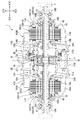
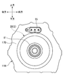
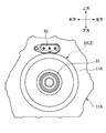
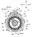
- FIG. 3 is an enlarged cross-sectional view of an upper portion of the rear wheel drive device shown in FIG. 2. It is the side view which looked at the edge part wall of the right side case which accommodates the right 2nd motor from the right side. It is the side view which looked at the edge part wall of the left side case which accommodates the left 1st motor from the left side. It is the side view which removed the right side case and looked at the 2nd electric motor on the right side from the right side. It is the side view which removed the left side case and looked at the left first motor from the left side. It is explanatory drawing explaining zero point correction
- a vehicle 3 shown in FIG. 1 is a hybrid vehicle having a drive device 6 (hereinafter referred to as a front wheel drive device) in which an internal combustion engine 4 and an electric motor 5 are connected in series at the front portion of the vehicle. While power is transmitted to the front wheels Wf via the transmission 7, a drive device 1 (hereinafter referred to as a rear wheel drive device) provided below the floor panel (not shown) at the rear of the vehicle separately from the front wheel drive device 6. Is transmitted to the rear wheels Wr (RWr, LWr).
- the rear wheel drive device 1 includes first and second electric motor bodies 2A and 2B.
- the power of the first electric motor body 2A is transmitted to the left rear wheel LWr, and the power of the second electric motor body 2B is transmitted to the right rear wheel RWr. Is done.
- the electric motor 5 of the front wheel drive device 6 and the first and second electric motor main bodies 2A, 2B of the rear wheel drive device 1 are connected to the battery 9 so that power supply from the battery 9 and energy regeneration to the battery 9 can be performed. ing.
- FIG. 2 is a longitudinal sectional view of the entire rear wheel drive device 1
- FIG. 3 is an enlarged partial sectional view of the upper part of FIG.
- a case 11 that is a housing of the rear wheel drive device 1 includes a central case 11M disposed substantially in the vehicle width direction (hereinafter also referred to as a left-right direction of the vehicle) and left and right sides of the central case 11M so as to sandwich the central case 11M.
- the left side case 11 ⁇ / b> A and the right side case 11 ⁇ / b> B are arranged in a substantially cylindrical shape.
- the axles 10A and 10B for the rear wheels Wr, the first and second electric motor bodies 2A and 2B for driving the axle, and the drive rotation of the first and second electric motor bodies 2A and 2B are decelerated.
- the first and second planetary gear type speed reducers 12A and 12B are arranged side by side on the same rotation axis x.
- the axle 10A, the first electric motor main body 2A and the first planetary gear speed reducer 12A drive and control the left rear wheel LWr
- the axle 10B, the second electric motor main body 2B and the second planetary gear speed reducer 12B are the right rear wheel RWr. Is controlled.
- the axle 10A, the first electric motor main body 2A and the first planetary gear speed reducer 12A, and the axle 10B, the second electric motor main body 2B and the second planetary gear speed reducer 12B are orthogonal to the rotation axis x in the case 11 and in the center. With respect to the intermediate surface M located, it is arrange
- Partition walls 18A and 18B extending radially inward are provided on the center case 11M side of the left and right side cases 11A and 11B, respectively, and the end walls 17A and 17B and the partition walls 18A and 18B of the left and right side cases 11A and 11B are provided. Between the first and second electric motor bodies 2A and 2B, respectively. Further, first and second planetary gear speed reducers 12A and 12B are arranged in a space surrounded by the central case 11M and the partition walls 18A and 18B.
- the rear wheel drive device 1 is provided with a breather device 40 that communicates the inside and outside of the case 11 so that the air inside the case 11 escapes to the outside through the breather chamber 41 so that the air does not become excessively high temperature and pressure.
- the breather chamber 41 is disposed at the upper part in the vertical direction of the case 11, and includes an outer wall of the central case 11M, a first cylindrical wall 43 extending substantially horizontally in the central case 11M on the left side case 11A side, and a right side case.
- a second cylindrical wall 44 extending substantially horizontally on the 11B side, a left and right dividing wall 45 connecting the inner ends of the first and second cylindrical walls 43, 44, and a left side case 11A of the first cylindrical wall 43.
- the first and second cylindrical walls 43 and 44 and the left and right dividing walls 45 that form the lower surface of the breather chamber 41 are such that the first cylindrical wall 43 is positioned radially inward from the second cylindrical wall 44, and the left and right dividing walls 45 are A third cylinder that extends from the inner end of the second cylindrical wall 44 to the inner end of the first cylindrical wall 43 while being bent while reducing the diameter, and further extends radially inward and extends substantially horizontally.
- Reach wall 46 The third cylindrical wall 46 is located on the inner side of both outer end portions of the first cylindrical wall 43 and the second cylindrical wall 44 and substantially in the center thereof.
- baffle plates 47A and 47B are provided in the space between the first cylindrical wall 43 and the outer wall of the central case 11M or the space between the second cylindrical wall 44 and the outer wall of the central case 11M as the first planet. It is fixed so as to be separated from the gear type speed reducer 12A or the second planetary gear type speed reducer 12B.
- the stators 14A and 14B are fixed to the left and right side cases 11A and 11B, respectively, and annular rotors 15A and 15B are provided on the inner peripheral sides of the stators 14A and 14B. It is arrange
- Cylindrical shafts 16A and 16B surrounding the outer periphery of the axles 10A and 10B are coupled to the inner peripheral portions of the rotors 15A and 15B, and the cylindrical shafts 16A and 16B can be relatively rotated coaxially with the axles 10A and 10B.
- the left and right cases 11A and 11B are supported by end walls 17A and 17B and partition walls 18A and 18B via bearings 19A and 19B.
- a resolver rotor 90 as a detector is attached to one end side of the cylindrical shafts 16A and 16B, and a resolver stator 93 as a detector for detecting the rotation state of the resolver rotor 90 is attached to the end walls 17A and 17B. Is attached so as to face the outer diameter side of the resolver rotor 90.
- the resolver rotor 90 and the resolver stator 93 constitute resolvers 20A and 20B.
- the resolvers 20A and 20B have the rotational state quantities of the rotors 15A and 15B such as the rotation angle, the angular velocity, the rotation speed, and the like in the first and second electric motor main bodies 2A, This is fed back to the 2B controller (not shown).
- the resolver rotor 90 and the rotors 15A, 15B of the first and second electric motor bodies 2A, 2B and the axles 10A, 10B provided on the cylindrical shafts 16A, 16B are the first and second planetary gear type reduction gears as will be described later. Since it is mechanically connected via the machines 12A and 12B, the wheel speed can also be calculated from the rotational state quantity and gear ratio of the rotors 15A and 15B.
- the resolver 20A constitutes the first electric motor 102A together with the first electric motor main body 2A
- the resolver 20B constitutes the second electric motor 102B together with the second electric motor main body 2B.
- the first and second planetary gear speed reducers 12A and 12B include sun gears 21A and 21B, a plurality of planetary gears 22A and 22B meshed with the sun gears 21A and 21B, and a planetary carrier 23A that supports these planetary gears 22A and 22B. , 23B and ring gears 24A, 24B meshed with the outer peripheral sides of the planetary gears 22A, 22B, and the drive rotations of the first and second electric motor bodies 2A, 2B are input from the sun gears 21A, 21B to reduce the drive The rotation is output to the axles 10A and 10B through the planetary carriers 23A and 23B.
- Sun gears 21A and 21B are formed integrally with cylindrical shafts 16A and 16B.
- the planetary gears 22A and 22B are double pinions having first pinions 26A and 26B having large diameters directly meshed with the sun gears 21A and 21B, and second pinions 27A and 27B having smaller diameters than the first pinions 26A and 26B.
- the first pinions 26A and 26B and the second pinions 27A and 27B are integrally formed in a state of being coaxial and offset in the axial direction.
- the planetary gears 22A and 22B are supported by the planetary carriers 23A and 23B so as to be capable of rotating and revolving, and the planetary carriers 23A and 23B are spline-fitted to the axles 10A and 10B with the axially inner ends extending inward in the radial direction. It is supported by the partition walls 18A and 18B through bearings 33A and 33B.
- the ring gears 24A and 24B have gear portions 28A and 28B that are meshed with the second pinions 27A and 27B whose inner peripheral surfaces are small diameters, and small diameters that are smaller than the gear portions 28A and 28B and that are opposed to each other at an intermediate position of the case 11.
- the gear portions 28A and 28B face each other in the axial direction with the third cylindrical wall 46 formed at the inner diameter side end of the left and right dividing wall 45 of the central case 11M.
- the outer diameter surfaces of the small diameter portions 29A and 29B are spline-fitted to an inner race 51 of a one-way clutch 50, which will be described later, and the ring gears 24A and 24B are connected to each other so as to rotate integrally with the inner race 51 of the one-way clutch 50. Configured.
- a hydraulic brake constituting braking means for the ring gear 24B 60 is arranged so as to overlap with the first pinion 26B in the radial direction and overlap with the second pinion 27B in the axial direction.
- the hydraulic brake 60 includes a plurality of fixed plates 35 that are spline-fitted to the inner peripheral surface of the second cylindrical wall 44 and a plurality of rotary plates 36 that are spline-fitted to the outer peripheral surface of the gear portion 28B of the ring gear 24B. These plates 35 and 36 are arranged so as to be fastened and released by an annular piston 37.
- the piston 37 is housed in an annular cylinder chamber formed between the left and right dividing walls 45 of the central case 11M and the third cylindrical wall 46 so as to freely advance and retract.
- the elastic member 39 supported by the seat is always urged in a direction to release the fixed plate 35 and the rotating plate 36.
- the working chamber into which oil is directly introduced is defined between the left and right dividing walls 45 and the piston 37.
- the piston 37 moves forward (rightward), and the fixed plate 35 and the rotating plate 36 are pressed against each other and fastened.
- the urging force of the elastic member 39 exceeds the pressure of the oil introduced into the working chamber S, the piston 37 moves backward (leftward movement), and the fixed plate 35 and the rotating plate 36 are separated and released.
- the hydraulic brake 60 is connected to an oil pump 70 (see FIG. 1).
- the fixed plate 35 is supported by the second cylindrical wall 44 extending from the left and right dividing walls 45 of the central case 11M constituting the case 11, while the rotating plate 36 is supported by the gear portion 28B of the ring gear 24B. Therefore, when the plates 35 and 36 are pressed by the piston 37, a braking force is applied to the ring gear 24B by the frictional engagement between the plates 35 and 36, and is fixed. When the fastening by the piston 37 is released from this state, the ring gear 24B is allowed to rotate freely.
- the braking force is also applied to the ring gear 24A when the hydraulic brake 60 is fastened, and the ring gear 24A is fixed when the hydraulic brake 60 is released. Free rotation is allowed.
- a space is secured between the coupling portions 30A and 30B of the ring gears 24A and 24B facing each other in the axial direction, and only power in one direction is transmitted to the ring gears 24A and 24B in the space to transmit power in the other direction.
- a one-way clutch 50 is arranged to be shut off.
- the one-way clutch 50 has a large number of sprags 53 interposed between an inner race 51 and an outer race 52.
- the inner race 51 is connected to the small diameter portions 29A, 29B of the ring gears 24A, 24B by spline fitting. It is configured to rotate integrally.
- the outer race 52 is positioned by the third cylindrical wall 46 and is prevented from rotating.
- the one-way clutch 50 is configured to engage and lock the rotation of the ring gears 24A and 24B when the vehicle 3 moves forward with the power of the first and second electric motor bodies 2A and 2B. More specifically, in the one-way clutch 50, rotational power in the forward direction (rotation direction when the vehicle 3 is advanced) on the first and second electric motor bodies 2A, 2B side is input to the rear wheel Wr side. When the rotational power in the reverse direction on the first and second electric motor main bodies 2A, 2B side is input to the rear wheel Wr side, the engagement state is reached and the forward direction on the rear wheel Wr side is sometimes reached.
- the one-way clutch 50 and the hydraulic brake 60 are provided in parallel on the power transmission path between the first and second electric motor bodies 2A, 2B and the rear wheel Wr. Yes.
- the hydraulic brake 60 is released, weakly engaged, or engaged by the pressure of oil supplied from the oil pump 70 according to the running state of the vehicle and the engaged / disengaged state of the one-way clutch 50. Be controlled. For example, when the vehicle 3 moves forward by powering driving of the first and second electric motor main bodies 2A and 2B (at low vehicle speed and medium vehicle speed), the one-way clutch 50 is engaged, so that power transmission is possible.
- the brake 60 By controlling the brake 60 in the weakly engaged state, the input of the forward rotational power from the first and second electric motor main bodies 2A, 2B side temporarily decreases, and the one-way clutch 50 is in the non-engaged state. Even in this case, it becomes possible to prevent power transmission from being disabled between the first and second electric motor main bodies 2A and 2B and the rear wheel Wr. Further, when the vehicle 3 moves forward by power driving of the internal combustion engine 4 and / or the electric motor 5 (at the time of high vehicle speed), the one-way clutch 50 is disengaged and the hydraulic brake 60 is controlled to be in a released state. Over-rotation of the first and second electric motor bodies 2A and 2B is prevented.
- the one-way clutch 50 is disengaged, so that the hydraulic brake 60 is controlled to be in the engaged state, so that the reverse direction from the first and second electric motor main bodies 2A and 2B side. Is output to the rear wheel Wr side, or forward rotational power on the rear wheel Wr side is input to the first and second electric motor main bodies 2A and 2B.
- resolvers 20A and 20B (hereinafter, resolvers 20A and 20B are referred to as resolver 20 when they are not distinguished.
- FIG. Here, a case will be described in which the first and second motor bodies 2A and 2B are three-phase AC motors, and zero point correction processing is performed based on the U phase. 4A, FIG. 4B, FIG. 5A and FIG.
- reference numeral 95 is a connector of the first and second electric motor bodies 2A and 2B, and the connector 95 of the first electric motor body 2A is the end wall 17A of the left side case 11A. And the connector 95 of the second electric motor main body 2B is arranged facing the outer side (right side) on the end wall 17B of the right side case 11B.
- a predetermined current is supplied to the stator 14 of the electric motor body 2 for the zero point correction, and the induced voltage of the electric motor body 2 obtained from the U phase is acquired. Further, the rotor 15 is rotated by the current supplied to the stator 14, and an electrical angle signal from the resolver stator 93 generated by the resolver rotor 90 rotating in conjunction with the rotation of the rotor 15 is acquired.
- FIG. 6 shows the U-phase current, U-phase induced voltage, and resolver electrical angle signal generated by the zero-point correction process.
- Zero-point correction is based on the relationship between the electrical angle of the U-phase current and the resolver 20 electrical angle.
- the correction amount is obtained, and the electrical angle of the resolver is corrected based on the correction amount.
- This zero point correction process is performed by the left and right first and second motors 102A and 102B because the motor body 2, the resolver 20, and the case 11 have dimensional errors and assembly errors, respectively.
- the left and right first and second motors 102A and 102B have correction values that are completely unrelated, numerical management becomes complicated. For this reason, it is useful in terms of numerical management to make the correction reference value that is a guideline for the correction value common.
- the relative position of the resolver stator 93 with respect to the reference position RS2 is based on one of the rotation directions of the first motor body 2A and the second motor body 2B (in this embodiment, the rotation direction when the vehicle 3 moves forward). Identical.
- Is the reference position MS1 of the stator 14A, and the connector center line RC1 passing through the center in the circumferential direction of the connector 94 of the resolver stator 93 and the rotation axis x is the reference position RS1 of the resolver stator 93.
- the U-phase coil center line MC2 passing through the circumferential center of one coil and the rotation axis x is set as the reference position MS2 of the stator 14B
- a connector center line RC ⁇ b> 2 passing through the circumferential center of the connector 94 and the rotation axis x is set as a reference position RS ⁇ b> 2 of the resolver stator 93.
- 5A and 5B are the same based on the rotation direction of the first electric motor main body 2A and the second electric motor main body 2B, that is, the forward direction when the vehicle 3 moves forward indicated by the arrows.
- any U-phase coil among a plurality (four in this embodiment) of U-phase coils may be used as a reference, but the reference position RS1 of the stator 14A of the first electric motor 102A and the stator 14B of the second electric motor 102B.
- the reference position RS2 is set to the same phase, that is, when the vertical line Y passing through the rotation axis x is used as a reference, for example, it is preferable to set the same phase in the forward direction from Y ( ⁇ ° in this embodiment). Thereby, the assembly
- the resolver stator 93 is not limited to the connector 94, and the reference position can be set at an arbitrary position as long as the resolver stator 93 is the same in the left and right resolver stators 93.
- first and second electric motor main bodies 2A and 2B are composed of the same member, and the resolvers 20A and 20B are also composed of the same member. Thereby, by sharing parts, the number of parts can be reduced, and the manufacturing cost can be reduced.
- the relative position between the reference position MS2 of the second motor 102B and the reference position RS2 of the resolver stator 93 of the second motor 102B is based on the rotation direction of the first motor body 2A and the second motor body 2B when the vehicle 3 moves forward. Since they are the same, the reference value for zero point correction is common, and numerical management becomes easy.
- this invention is not limited to embodiment mentioned above, A deformation
- a hybrid vehicle has been described as an applicable vehicle.
- the present invention is not limited to this, and may be, for example, an electric vehicle using only a motor as a drive source.
- Rear wheel drive system (motor unit) 2A 1st motor body (motor body) 2B 2nd electric motor body (motor body) 3 Vehicle 14A, 14B Stator (stator) 15A, 15B Rotor (rotor) 16A, 16B Cylindrical shaft (rotating body) 20A, 20B resolver (rotation state quantity detector) 90 Resolver rotor (detector) 93 Resolver stator (detector) MS1 reference position (reference position of the stator of the first motor) MS2 reference position (reference position of the stator of the second motor) RS1 reference position (reference position of the detector of the first motor) RS2 reference position (reference position of the detector of the second motor)
Landscapes
- Engineering & Computer Science (AREA)
- Transportation (AREA)
- Mechanical Engineering (AREA)
- Chemical & Material Sciences (AREA)
- Combustion & Propulsion (AREA)
- Power Engineering (AREA)
- Microelectronics & Electronic Packaging (AREA)
- Automation & Control Theory (AREA)
- Electric Propulsion And Braking For Vehicles (AREA)
- Hybrid Electric Vehicles (AREA)
- Arrangement Or Mounting Of Propulsion Units For Vehicles (AREA)
- Control Of Multiple Motors (AREA)
Abstract
Description
第1態様は、
車両(例えば、後述の実施形態の車両3)の左車輪(例えば、後述の実施形態の左後輪LWr)に接続される第1電動機(例えば、後述の実施形態の第1電動機102A)と、
前記車両の右車輪(例えば、後述の実施形態の右後輪RWr)に接続される第2電動機(例えば、後述の実施形態の第2電動機102B)と、を備え、
該第1電動機及び該第2電動機は、
固定子(例えば、後述の実施形態のステータ14A、14B)と、該固定子に対して相対回転可能に配設される回転子(例えば、後述の実施形態のロータ15A、15B)と、を有する電動機本体(例えば、後述の実施形態の第1電動機本体2A、第2電動機本体2B)と、
前記回転子又は前記回転子と連動して回転する回転体(例えば、後述の実施形態の円筒軸16A、16B)に設置される被検出子(例えば、後述の実施形態のレゾルバロータ90)と、前記被検出子の回転状態を検出する検出器(例えば、後述の実施形態のレゾルバステータ93)と、を有する回転状態量検出装置(例えば、後述の実施形態のレゾルバ20A、20B)と、をそれぞれ有する、電動機ユニット(例えば、後述の実施形態の後輪駆動装置1)であって、
前記第1電動機の前記固定子の基準位置(例えば、後述の実施形態の基準位置MS1)と前記第1電動機の前記検出器の基準位置(例えば、後述の実施形態の基準位置RS1)との相対位置と、
前記第2電動機の前記固定子の基準位置(例えば、後述の実施形態の基準位置MS2)と前記第2電動機の前記検出器の基準位置(例えば、後述の実施形態の基準位置RS2)との相対位置と、が前記第1電動機及び前記第2電動機の前記車両の前進時又は後進時の回転方向を基準にして、同一である。
前記回転方向において、前記第1電動機の前記固定子の基準位置と前記第2電動機の前記固定子の基準位置とが同一の位相にある。
前記第1電動機及び前記第2電動機は筺体に収容され、
前記第1電動機の前記電動機本体と前記第2電動機の前記電動機本体は、同一の部材から構成され、
前記第1電動機の前記回転状態量検出装置と前記第2電動機の前記回転状態量検出装置は、同一の部材から構成されている。
図1に示す車両3は、内燃機関4と電動機5が直列に接続された駆動装置6(以下、前輪駆動装置と呼ぶ。)を車両前部に有するハイブリッド車両であり、この前輪駆動装置6の動力がトランスミッション7を介して前輪Wfに伝達される一方で、この前輪駆動装置6と別に、車両後部のフロアパネル(不図示)よりも下方に設けられた駆動装置1(以下、後輪駆動装置と呼ぶ。)の動力が後輪Wr(RWr、LWr)に伝達されるようになっている。後輪駆動装置1は、第1及び第2電動機本体2A、2Bを備え、第1電動機本体2Aの動力が左後輪LWrに伝達され、第2電動機本体2Bの動力が右後輪RWrに伝達される。前輪駆動装置6の電動機5と後輪駆動装置1の第1及び第2電動機本体2A、2Bは、バッテリ9に接続され、バッテリ9からの電力供給と、バッテリ9へのエネルギー回生が可能となっている。
例えば、上記実施形態では、適用車両としてハイブリッド車両について説明したが、本発明はこれに限定されるものでなく、例えば、モータのみを駆動源とする電気自動車であってもよい。
また、上記実施形態では、2つの第1及び第2電動機本体2A、2Bと、第1及び第2遊星歯車式減速機12A、12Bと、これら第1及び第2電動機本体2A、2B及び第1及び第2遊星歯車式減速機12A、12Bを収容するケース11と、2つのレゾルバ20A、20Bと、を有する後輪駆動装置1を例示したが、本発明の電動機ユニットとしては、2つの電動機が電動機本体と、回転状態量検出装置とをそれぞれ有していればよい。
2A 第1電動機本体(電動機本体)
2B 第2電動機本体(電動機本体)
3 車両
14A、14B ステータ(固定子)
15A、15B ロータ(回転子)
16A、16B 円筒軸(回転体)
20A、20B レゾルバ(回転状態量検出装置)
90 レゾルバロータ(被検出子)
93 レゾルバステータ(検出器)
MS1 基準位置(第1電動機の固定子の基準位置)
MS2 基準位置(第2電動機の固定子の基準位置)
RS1 基準位置(第1電動機の検出器の基準位置)
RS2 基準位置(第2電動機の検出器の基準位置)
Claims (3)
- 車両の左車輪に接続される第1電動機と、
前記車両の右車輪に接続される第2電動機と、を備え、
該第1電動機及び該第2電動機は、
固定子と、該固定子に対して相対回転可能に配設される回転子と、を有する電動機本体と、
前記回転子又は前記回転子と連動して回転する回転体に設置される被検出子と、前記被検出子の回転状態を検出する検出器と、を有する回転状態量検出装置と、をそれぞれ有する、電動機ユニットであって、
前記第1電動機の前記固定子の基準位置と前記第1電動機の前記検出器の基準位置との相対位置と、
前記第2電動機の前記固定子の基準位置と前記第2電動機の前記検出器の基準位置との相対位置と、が前記第1電動機及び前記第2電動機の前記車両の前進時又は後進時の回転方向を基準にして、同一である、電動機ユニット。 - 請求項1に記載の電動機ユニットであって、
前記回転方向において、前記第1電動機の前記固定子の基準位置と前記第2電動機の前記固定子の基準位置とが同一の位相にある、電動機ユニット。 - 請求項2に記載の電動機ユニットであって、
前記第1電動機及び前記第2電動機は筺体に収容され、
前記第1電動機の前記電動機本体と前記第2電動機の前記電動機本体は、同一の部材から構成され、
前記第1電動機の前記回転状態量検出装置と前記第2電動機の前記回転状態量検出装置は、同一の部材から構成されている、電動機ユニット。
Priority Applications (4)
| Application Number | Priority Date | Filing Date | Title |
|---|---|---|---|
| US16/083,983 US20200295643A1 (en) | 2016-03-29 | 2017-03-27 | Electric motor unit |
| EP17774978.5A EP3437909A4 (en) | 2016-03-29 | 2017-03-27 | ELECTRIC MOTOR UNIT |
| CN201780019298.2A CN108883693A (zh) | 2016-03-29 | 2017-03-27 | 电动机单元 |
| JP2018508011A JPWO2017170441A1 (ja) | 2016-03-29 | 2017-03-27 | 電動機ユニット |
Applications Claiming Priority (2)
| Application Number | Priority Date | Filing Date | Title |
|---|---|---|---|
| JP2016-065530 | 2016-03-29 | ||
| JP2016065530 | 2016-03-29 |
Publications (1)
| Publication Number | Publication Date |
|---|---|
| WO2017170441A1 true WO2017170441A1 (ja) | 2017-10-05 |
Family
ID=59965559
Family Applications (1)
| Application Number | Title | Priority Date | Filing Date |
|---|---|---|---|
| PCT/JP2017/012464 Ceased WO2017170441A1 (ja) | 2016-03-29 | 2017-03-27 | 電動機ユニット |
Country Status (5)
| Country | Link |
|---|---|
| US (1) | US20200295643A1 (ja) |
| EP (1) | EP3437909A4 (ja) |
| JP (1) | JPWO2017170441A1 (ja) |
| CN (1) | CN108883693A (ja) |
| WO (1) | WO2017170441A1 (ja) |
Citations (2)
| Publication number | Priority date | Publication date | Assignee | Title |
|---|---|---|---|---|
| JP2005080430A (ja) * | 2003-09-01 | 2005-03-24 | Tamagawa Seiki Co Ltd | レゾルバ内蔵型モータ |
| JP5750501B2 (ja) * | 2013-12-26 | 2015-07-22 | 本田技研工業株式会社 | 電動機 |
Family Cites Families (4)
| Publication number | Priority date | Publication date | Assignee | Title |
|---|---|---|---|---|
| JP4007197B2 (ja) * | 2003-01-16 | 2007-11-14 | トヨタ自動車株式会社 | モータ制御装置 |
| JP5414636B2 (ja) * | 2010-08-24 | 2014-02-12 | 本田技研工業株式会社 | 車両用駆動装置 |
| KR101537916B1 (ko) * | 2011-11-22 | 2015-07-17 | 혼다 기켄 고교 가부시키가이샤 | 전동기의 접속 기구 |
| US20150061547A1 (en) * | 2013-09-05 | 2015-03-05 | Milad Gougani | Locking and Synchronizing Controller for Hall-sensor Driven Motors |
-
2017
- 2017-03-27 EP EP17774978.5A patent/EP3437909A4/en not_active Withdrawn
- 2017-03-27 WO PCT/JP2017/012464 patent/WO2017170441A1/ja not_active Ceased
- 2017-03-27 JP JP2018508011A patent/JPWO2017170441A1/ja active Pending
- 2017-03-27 US US16/083,983 patent/US20200295643A1/en not_active Abandoned
- 2017-03-27 CN CN201780019298.2A patent/CN108883693A/zh not_active Withdrawn
Patent Citations (2)
| Publication number | Priority date | Publication date | Assignee | Title |
|---|---|---|---|---|
| JP2005080430A (ja) * | 2003-09-01 | 2005-03-24 | Tamagawa Seiki Co Ltd | レゾルバ内蔵型モータ |
| JP5750501B2 (ja) * | 2013-12-26 | 2015-07-22 | 本田技研工業株式会社 | 電動機 |
Non-Patent Citations (1)
| Title |
|---|
| See also references of EP3437909A4 * |
Also Published As
| Publication number | Publication date |
|---|---|
| US20200295643A1 (en) | 2020-09-17 |
| CN108883693A (zh) | 2018-11-23 |
| EP3437909A4 (en) | 2019-05-22 |
| JPWO2017170441A1 (ja) | 2018-12-13 |
| EP3437909A1 (en) | 2019-02-06 |
Similar Documents
| Publication | Publication Date | Title |
|---|---|---|
| JP5965700B2 (ja) | 車両用駆動装置 | |
| US9174526B2 (en) | Drive controller for vehicle | |
| JP5677142B2 (ja) | インホイール型の車輪駆動装置 | |
| CN104245456B (zh) | 车辆用驱动装置 | |
| CN103958928B (zh) | 动力传递装置 | |
| JP5572779B2 (ja) | 車両用駆動装置及び車両用駆動装置の制御方法 | |
| US9114725B2 (en) | Vehicle drive device and method for controlling vehicle drive device | |
| JP5750501B2 (ja) | 電動機 | |
| JP5478595B2 (ja) | 車両用駆動装置 | |
| JP2012091759A (ja) | 車両駆動装置 | |
| JP5948109B2 (ja) | 車両用駆動装置 | |
| JP2015173537A (ja) | 電動機 | |
| JP6014346B2 (ja) | 車両用駆動装置 | |
| JP5820904B2 (ja) | 遊星歯車機構の支持構造 | |
| JP5965677B2 (ja) | 車両用駆動装置及び車両用駆動装置の制御方法 | |
| JP5914115B2 (ja) | 車両用駆動装置 | |
| JPWO2017170441A1 (ja) | 電動機ユニット | |
| KR20190063700A (ko) | 인휠 구동장치 | |
| JP5520903B2 (ja) | 電動機の制御装置 | |
| JP6808521B2 (ja) | 遊星歯車機構の支持構造 | |
| JP6302628B2 (ja) | 駆動装置及び駆動装置の制御方法 | |
| JP2015127177A (ja) | 車両 | |
| JP6167038B2 (ja) | 駆動装置 | |
| JP6749190B2 (ja) | 左右輪駆動装置の異常検出装置および異常検出方法 | |
| JP2018154151A (ja) | 車両用駆動装置 |
Legal Events
| Date | Code | Title | Description |
|---|---|---|---|
| WWE | Wipo information: entry into national phase |
Ref document number: 2018508011 Country of ref document: JP |
|
| NENP | Non-entry into the national phase |
Ref country code: DE |
|
| WWE | Wipo information: entry into national phase |
Ref document number: 2017774978 Country of ref document: EP |
|
| ENP | Entry into the national phase |
Ref document number: 2017774978 Country of ref document: EP Effective date: 20181029 |
|
| 121 | Ep: the epo has been informed by wipo that ep was designated in this application |
Ref document number: 17774978 Country of ref document: EP Kind code of ref document: A1 |