WO2017170520A1 - コントロール器 - Google Patents
コントロール器 Download PDFInfo
- Publication number
- WO2017170520A1 WO2017170520A1 PCT/JP2017/012592 JP2017012592W WO2017170520A1 WO 2017170520 A1 WO2017170520 A1 WO 2017170520A1 JP 2017012592 W JP2017012592 W JP 2017012592W WO 2017170520 A1 WO2017170520 A1 WO 2017170520A1
- Authority
- WO
- WIPO (PCT)
- Prior art keywords
- label body
- controller
- unit
- protrusion
- housing
- Prior art date
- Legal status (The legal status is an assumption and is not a legal conclusion. Google has not performed a legal analysis and makes no representation as to the accuracy of the status listed.)
- Ceased
Links
Images


Classifications
-
- H—ELECTRICITY
- H01—ELECTRIC ELEMENTS
- H01H—ELECTRIC SWITCHES; RELAYS; SELECTORS; EMERGENCY PROTECTIVE DEVICES
- H01H9/00—Details of switching devices, not covered by groups H01H1/00 - H01H7/00
- H01H9/18—Distinguishing marks on switches, e.g. for indicating switch location in the dark; Adaptation of switches to receive distinguishing marks
-
- H—ELECTRICITY
- H04—ELECTRIC COMMUNICATION TECHNIQUE
- H04N—PICTORIAL COMMUNICATION, e.g. TELEVISION
- H04N21/00—Selective content distribution, e.g. interactive television or video on demand [VOD]
- H04N21/40—Client devices specifically adapted for the reception of or interaction with content, e.g. set-top-box [STB]; Operations thereof
- H04N21/41—Structure of client; Structure of client peripherals
- H04N21/422—Input-only peripherals, i.e. input devices connected to specially adapted client devices, e.g. global positioning system [GPS]
- H04N21/42204—User interfaces specially adapted for controlling a client device through a remote control device; Remote control devices therefor
- H04N21/42206—User interfaces specially adapted for controlling a client device through a remote control device; Remote control devices therefor characterized by hardware details
- H04N21/4221—Dedicated function buttons, e.g. for the control of an EPG, subtitles, aspect ratio, picture-in-picture or teletext
-
- H—ELECTRICITY
- H04—ELECTRIC COMMUNICATION TECHNIQUE
- H04N—PICTORIAL COMMUNICATION, e.g. TELEVISION
- H04N21/00—Selective content distribution, e.g. interactive television or video on demand [VOD]
- H04N21/40—Client devices specifically adapted for the reception of or interaction with content, e.g. set-top-box [STB]; Operations thereof
- H04N21/41—Structure of client; Structure of client peripherals
- H04N21/422—Input-only peripherals, i.e. input devices connected to specially adapted client devices, e.g. global positioning system [GPS]
- H04N21/42204—User interfaces specially adapted for controlling a client device through a remote control device; Remote control devices therefor
- H04N21/42226—Reprogrammable remote control devices
- H04N21/42227—Reprogrammable remote control devices the keys being reprogrammable, e.g. soft keys
-
- H—ELECTRICITY
- H04—ELECTRIC COMMUNICATION TECHNIQUE
- H04Q—SELECTING
- H04Q9/00—Arrangements in telecontrol or telemetry systems for selectively calling a substation from a main station, in which substation desired apparatus is selected for applying a control signal thereto or for obtaining measured values therefrom
-
- H—ELECTRICITY
- H01—ELECTRIC ELEMENTS
- H01H—ELECTRIC SWITCHES; RELAYS; SELECTORS; EMERGENCY PROTECTIVE DEVICES
- H01H2203/00—Form of contacts
- H01H2203/018—Form of contacts binary coded
-
- H—ELECTRICITY
- H01—ELECTRIC ELEMENTS
- H01H—ELECTRIC SWITCHES; RELAYS; SELECTORS; EMERGENCY PROTECTIVE DEVICES
- H01H2221/00—Actuators
- H01H2221/032—Actuators adjustable
- H01H2221/034—Coded keys
-
- H—ELECTRICITY
- H01—ELECTRIC ELEMENTS
- H01H—ELECTRIC SWITCHES; RELAYS; SELECTORS; EMERGENCY PROTECTIVE DEVICES
- H01H2239/00—Miscellaneous
- H01H2239/026—Internal encoding, e.g. validity bit
-
- H—ELECTRICITY
- H04—ELECTRIC COMMUNICATION TECHNIQUE
- H04N—PICTORIAL COMMUNICATION, e.g. TELEVISION
- H04N21/00—Selective content distribution, e.g. interactive television or video on demand [VOD]
- H04N21/40—Client devices specifically adapted for the reception of or interaction with content, e.g. set-top-box [STB]; Operations thereof
- H04N21/41—Structure of client; Structure of client peripherals
- H04N21/422—Input-only peripherals, i.e. input devices connected to specially adapted client devices, e.g. global positioning system [GPS]
- H04N21/42204—User interfaces specially adapted for controlling a client device through a remote control device; Remote control devices therefor
- H04N21/42206—User interfaces specially adapted for controlling a client device through a remote control device; Remote control devices therefor characterized by hardware details
- H04N21/42212—Specific keyboard arrangements
Definitions
- This disclosure relates to a controller for controlling an electrical device.
- Patent Document 1 discloses a learning remote control device corresponding to control of a plurality of devices.
- This learning remote control device includes a function name display unit.
- the function assigned to each key as a result of learning so far is displayed on this function name display unit according to the electric device to be controlled designated by the user during operation. .
- Patent Document 2 discloses a remote control device in which the arrangement of keys can be changed.
- each key has transmission code specifying information.
- the remote controller reads the transmission code specifying information that the key has. Then, the remote controller generates a transmission code corresponding to the read transmission code specifying information, and transmits the transmission code to the target device.
- This disclosure provides a controller that can easily customize the assignment of functions to operation units such as keys.
- a controller for controlling an electric device includes an output unit that outputs a signal for causing the electric device to perform a predetermined operation, and a contactor at least partially elastically displaceable in a predetermined direction.
- a function switch unit including a plurality of switches that are switched in an open / closed state when at least a part of the contactor is displaced in the predetermined direction, a display unit, and a protrusion protruding from the display unit, A label body that is attached in a state where the protrusion is inserted into a hole of the housing and the display portion is outside the housing.
- the protrusion of the label body determines a combination of open / closed states of the plurality of switches that are switched by pressing and displacing at least a part of the contacts of the plurality of switches in the predetermined direction.
- the predetermined operation is determined according to the combination.
- the controller in the present disclosure can easily customize the assignment of functions to operation units such as keys.
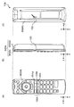
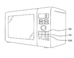
- FIG. 1A is a plan view schematically illustrating an example of an appearance of a control device including a control device according to the present disclosure.
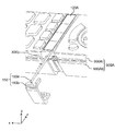
- FIG. 1B is a perspective view schematically illustrating an example of the appearance of a control device including a controller according to the present disclosure.
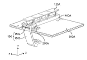
- FIG. 2 is a perspective view schematically showing an example of a part of a controller provided in the control device according to the first embodiment.
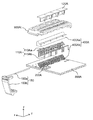
- FIG. 3A is an exploded perspective view schematically showing a part of the controller shown in FIG.
- FIG. 3B is an exploded perspective view schematically showing a part of the controller shown in FIG. 2.
- FIG. 4A is a cross-sectional view schematically showing an example of a part of a controller provided in the control device according to Embodiment 1.
- FIG. 1A is a plan view schematically illustrating an example of an appearance of a control device including a control device according to the present disclosure.
- FIG. 1B is a perspective view schematically illustrating an example of the appearance of a control device
- FIG. 4B is a cross-sectional view schematically illustrating an example of a part of a controller included in the control device according to Embodiment 1.
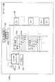
- FIG. 5 is a block diagram showing an example of the configuration of the controller in the first embodiment.
- FIG. 6 is an exploded perspective view schematically illustrating an example of a part of a controller provided in the control device according to the first modification of the first embodiment.
- FIG. 7A is a cross-sectional view schematically illustrating an example of a part of a controller included in the control device according to the first modification of the first embodiment.
- FIG. 7B is a cross-sectional view schematically illustrating an example of a part of a controller included in the control device according to the first modification of the first embodiment.
- FIG. 7A is a cross-sectional view schematically illustrating an example of a part of a controller included in the control device according to the first modification of the first embodiment.
- FIG. 7B is a cross-sectional view schematically illustrating an example of a
- FIG. 8 is a block diagram showing an example of the configuration of the controller in the first modification of the first embodiment.
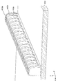
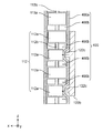
- FIG. 9 is an exploded perspective view schematically showing an example of a part of a controller provided in the control device according to the second modification of the first embodiment.
- FIG. 10 is a transparent perspective view schematically illustrating an example of a part of a controller provided in the control device according to the second modification of the first embodiment.
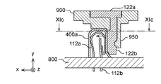
- FIG. 11A is a cross-sectional view schematically illustrating an example of a part of a controller included in the control device according to the second modification of the first embodiment.
- FIG. 11B is a cross-sectional view schematically illustrating an example of a part of a controller included in the control device according to the second modification of the first embodiment.
- FIG. 11C is a cross-sectional view schematically illustrating an example of a part of a controller included in the control device according to the second modification of the first embodiment.
- FIG. 12 is a perspective view schematically showing an example of a function switch unit included in the controller in the second embodiment.
- FIG. 13A is a cross-sectional view schematically illustrating an example of a part of a controller included in the control device according to Embodiment 2.
- FIG. 13B is a cross-sectional view schematically illustrating an example of a part of a controller included in the control device according to Embodiment 2.
- FIG. 14 is a diagram schematically illustrating an example of the appearance of a control device including the controller in the third embodiment.
- FIG. 15A is a perspective view schematically showing an example of a label body in the third exemplary embodiment.
- FIG. 15B is a perspective view schematically showing an example of a label body in the third exemplary embodiment.
- FIG. 15C is a side view schematically showing an example of the label body in the third exemplary embodiment.
- FIG. 16A is an exploded perspective view schematically showing an example of a part of the controller in the third embodiment.
- FIG. 16B is a diagram schematically illustrating an example of a procedure for attaching the label body and the label body fixing tool to the control device according to the third embodiment.
- FIG. 16C is a perspective view schematically showing an example of a part of the controller in the third embodiment.
- FIG. 16A is an exploded perspective view schematically showing an example of a part of the controller in the third embodiment.
- FIG. 16B is a diagram schematically illustrating an example of a procedure for attaching the label body and the label body fixing tool to the control device according to the third embodiment.
- FIG. 16D is a perspective view schematically showing an example of a part of the controller in the third embodiment.
- FIG. 17A is a cross-sectional view schematically showing an example of the structure of the controller in the third embodiment.
- FIG. 17B is a cross-sectional view schematically showing an example of the structure of the controller in the third embodiment.
- FIG. 18 is a block diagram showing an example of the configuration of the controller in the third embodiment.
- FIG. 19A is a diagram schematically illustrating a state where the label body fixing tool is used for other purposes in the controller in the third embodiment.
- FIG. 19B is a diagram schematically illustrating an example of an insertion position when the penetrating body of the label body fixing tool is inserted into the control device in the control device in the third exemplary embodiment.
- FIG. 20 is a diagram schematically illustrating an example of the appearance of a control device according to another embodiment.
- a surface provided with a key is referred to as an upper surface
- a surface opposite to the surface provided with a key is referred to as a bottom surface or a back surface.
- Each drawing shows three axes, x-axis, y-axis, and z-axis.
- the long direction of the control device is the x-axis
- the short direction of the control device is the z-axis
- the direction perpendicular to the x-axis and z-axis is the y-axis.
- these axes and directions are merely shown for convenience, and do not limit the present disclosure.
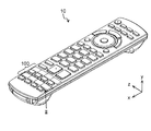
- FIG. 1A is a plan view schematically illustrating an example of an appearance of a control device 10 including a control device according to the present disclosure.
- FIG. 1B is a perspective view schematically illustrating an example of the appearance of the control device 10 including the controller 100 according to the present disclosure.
- control device 10 is a remote controller for wirelessly controlling a television receiver (hereinafter also referred to as “television receiver”).
- television receiver hereinafter also referred to as “television receiver”.
- the keys 501 to 508 and the label bodies 121 to 128 that are part of the components of the controller 100. Only the surface of is exposed.
- the key 501 to the key 508 are collectively referred to as a key 500, or a part of the keys 501 to 508, or a part thereof.
- the label bodies 121 to 128 are collectively referred to as a label body 120, or a part of them, or any of them without particular distinction.
- the key 500 is an example of an operation unit that a user operates to wirelessly control an electric device to be controlled.
- the user performs an operation of pressing the key 500 to wirelessly control the television receiver.
- a display showing an operation performed by the electric device to be controlled in response to a user operation (pressing the key 500) on the key 500 corresponding to the attachment position of each label body 120.
- 1A and FIG. 1B are attached by printing, unevenness (for example, embossing) or the like.
- This display is indicated by, for example, characters, symbols, figures, or combinations thereof.
- the attachment position of the label body 121 corresponds to the key 501, and on the surface of the label body 121, an operation that the control device 10 causes the television receiver to execute when the key 501 is pressed (for example, a display (character or symbol, etc.) indicating the Internet connection screen display) is attached.
- the attachment position of the label body 122 corresponds to the key 502, and an operation (for example, main sound and sub sound) that the control apparatus 10 performs on the surface of the label body 122 when the key 502 is pressed is performed.
- a display (character or symbol, etc.) indicating that the voice is switched to and from each other.
- the attachment positions of the label bodies 123 to 128 correspond to the keys 503 to 508, and the keys 503 to 508 are pressed on the surfaces of the label bodies 123 to 128, respectively.
- a display (characters or symbols, etc.) indicating the operation that the control device 10 causes the television receiver to execute is given.
- the label body 120 can be attached to and detached from the housing of the control device 10, and the attachment positions of the label body 120 can be interchanged. Then, by switching the mounting positions of the label bodies 120, the operation that the control device 10 causes the television receiver to perform when the keys 500 are pressed is switched between the keys 500 corresponding to the label bodies 120. .
- another label body (not shown) (referred to as a label body 129) may be replaced with one of the label body 121 to the label body 128 and attached.
- the control device 10 causes the electric device to be controlled to operate regardless of which of the keys 501 to 508 is pressed).
- New operation that could not be executed by the user) can be assigned to the key 500 corresponding to the label body 129.
- the control device 10 is attached to a television receiver having a web page display function, and the initial state of the control device 10 (before the label body 129 and any of the label bodies 121 to 128 are replaced). ), It is assumed that any of the keys 501 to 508 is assigned to control reception of a television broadcast by the television receiver or to control a video recorder connected to the television receiver. In such a case, for example, by removing the label body 121 from the control device 10 and attaching the label body 129 instead of the label body 121, the key 501 corresponding to the label body 121 can be initially set. A new operation that has not been performed (for example, an operation in which a specific website is displayed on the television receiver when the key 501 is pressed) can be assigned.
- the controller 100 according to the present disclosure can change the function of the operation unit corresponding to the label body 120 by exchanging the label bodies 120 with each other or by newly exchanging them. That is, in the controller 100 according to the present disclosure, the user can easily customize the function assignment to the operation unit. Note that “easy” in the present disclosure means that the user does not need to perform any work or setting other than the replacement of the label body 120 when changing the assignment of the function to the operation unit.
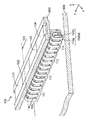
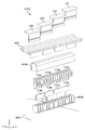
- FIG. 2 is a diagram schematically illustrating an example of a part of the controller 100 included in the control device 10 according to the first embodiment.
- FIG. 2 shows a perspective view of the region surrounded by the alternate long and short dash line in FIG. 1B from the direction of arrow II.
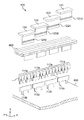
- FIG. 3A and 3B are exploded perspective views schematically showing a part of the controller 100 shown in FIG.
- FIG. 3A shows a view of the region surrounded by the alternate long and short dash line in FIG. 1B as seen from the arrow II (a view of the portion seen from substantially the same direction as FIG. 2), and
- FIG. 3B shows the portion at another angle ( The figure seen from the reverse direction of FIG. 3A is shown.
- the portion including label body 125 to label body 128 has substantially the same configuration as the portion including label body 121 to label body 124 described below. The description is omitted.
- the controller 100 includes a label body 121 to a label body 124, and a function switch unit 111 to a function switch unit 114.
- the function switch unit 111 to the function switch unit 114 are collectively referred to as a function switch unit 110, or a part of the function switch unit 111 to the function switch unit 114 are collectively referred to.
- the label body 120 is attached to the controller 100 (housing 900) such that the surface of the label body 120 is exposed on the housing 900 of the control device 10.
- Such a label body 120 and the casing 900 are, for example, molded products of ABS resin (Acrylonitrile Butadiene Styleene resin).
- the function switch unit 110 includes a plurality of switches 110AB that are pairs of a movable contact 110a and a fixed contact 110b.
- the movable contact 110 a and the fixed contact 110 b are each mounted on the substrate 800 of the control device 10.
- Each of the movable contact 110a and the fixed contact 110b is formed by molding a conductor such as a metal plate.
- the movable contact 110a and the fixed contact 110b are examples of contacts.
- FIGS. 2 to 3B illustrate 16 movable contacts 110a and four fixed contacts 110b.
- four movable contacts 110a continuous in the z-axis direction are paired with one fixed contact 110b.
- a pair of one movable contact 110a and one fixed contact 110b commonly used by the four movable contacts 110a forms one switch 110AB.
- four switches 110AB are formed by one fixed contact 110b.
- one fixed contact 110b and four movable contacts 110a that form four switches 110AB when paired with the fixed contact 110b form one function switch 110.
- the switch 110AB included in the function switch unit 111 is referred to as a “switch 111AB”, and the function switch unit 112 includes
- the switch 110AB included may be referred to as “switch 112AB”
- the switch 110AB included in the function switch unit 113 may be referred to as “switch 113AB”
- the switch 110AB included in the function switch unit 114 may be referred to as “switch 114AB” (FIG. 3A and FIG. 3B).
- the movable contact member 110a included in the function switch unit 111 is referred to as a “movable contact member 111a”.
- the movable contact 110a included in the unit 112 is referred to as “movable contact 112a”
- the movable contact 110a included in the function switch unit 113 is referred to as “movable contact 113a”
- the movable contact included in the function switch unit 114. 110a may be referred to as “movable contact 114a” (see FIGS. 3A and 3B).
- the fixed contact 110b included in the function switch unit 111 is referred to as a “fixed contact 111b”, and the function switch
- the fixed contact 110b included in the unit 112 is referred to as “fixed contact 112b”
- the fixed contact 110b included in the function switch unit 113 is referred to as “fixed contact 113b”
- the fixed contact included in the function switch unit 114 may be referred to as a “fixed contact 114b” (see FIGS. 3A and 3B).
- the movable contactor 110a illustrated in FIGS. 3A and 3B is formed by molding a long metal plate into a substantially inverted J shape. A part of one end side in the longitudinal direction of the metal plate is inserted into the substrate 800 and attached to the substrate 800, and the other end side in the longitudinal direction of the metal plate is above the substrate 800 (y axis positive direction side). Placed in.
- a portion above the substrate 800 of the metal plate (hereinafter also referred to as a movable portion) has a positive force in the x-axis direction. When added, it is displaced in that direction. If the amount of displacement at this time is within the elastic range of the metal plate, the movable part returns to the original position when the force is removed.
- the fixed contact 110b illustrated in FIGS. 3A and 3B is a metal plate provided with a plate-like portion and two legs for attaching to the substrate 800.
- the stationary contact 110b is attached to the substrate 800 in such a posture and position that the plate-like portion is accommodated in the movable portions of the plurality of movable contacts 110a. Then, when the movable part of the movable contact 110a is displaced as described above, the contact state between the movable contact 110a and the fixed contact 110b changes. As a result, the open / close state of the switch 110AB is switched. This operation will be described later.
- label body 120 Since the basic shape and size of the label body 120 (label body 121 to label body 124) are substantially the same, the label body 121 will be described as an example here.
- the label body 121 includes a display part 121a and a protruding part 121b.
- the surface exposed when the label body 121 is attached to the casing 900 of the control device 10 is a part of the display unit 121a.
- the protruding portion 121b of the label body 121 is inserted into the hole 910 provided in the housing 900 while moving in the y-axis direction.
- the label body 121 is attached to the controller 100 (housing 900) in a state where the display unit 121a is outside the housing 900.
- Each of the label bodies 121 to 124 has one or more ribs having the same shape and projecting in the positive x-axis direction on the side surfaces on the positive x-axis direction side of the protrusions 121b to 124b. 120c.
- Each of the label bodies 121 to 124 has a recess 120d provided on the side surface (opposite side) opposite to the side surface where the ribs 120c of the protruding portions 121b to 124b are provided.
- the ribs 120c included in the label body 121 are referred to as “ribs 121c”, and the ribs 120c included in the label body 122 are referred to as “ribs”.
- 122c ", the rib 120c included in the label body 123 may be referred to as” rib 123c ", and the rib 120c included in the label body 124 may be referred to as” rib 124c ".
- the recesses 120d included in the label body 121 are referred to as “recesses 121d”, and the recesses 120d included in the label body 122 are referred to as “recesses”.
- 122d ", the recess 120d included in the label body 123 may be referred to as” recess 123d ", and the recess 120d included in the label body 124 may be referred to as” recess 124d ".
- each of the label body 121 to the label body 124 can exchange the mounting position on the housing 900 with each other.
- the number and arrangement positions of the ribs 120c standing on the side surfaces on the x-axis positive direction side of the protrusions 121b to 124b are different from each other. That is, in the present embodiment, each of the label bodies 121 to 124 has a different number of ribs 120c at different arrangement positions. In the present embodiment, the maximum number of ribs 120c included in each label body 120 is four.
- the maximum number of ribs 120c included in the label body 120 is not limited to four. Further, the number of switches 110AB included in the function switch unit 112 is not limited to four. The number of ribs 120c included in the label body 120 may be set appropriately according to the number of switches 110AB included in the function switch unit 112.
- each rib 120c abuts on the movable part of the movable contact 110a opposite to the rib 120c so that the movable part is in a predetermined direction. It is formed in a shape and a position that can be pushed to. In the example shown in FIG. 3A, this predetermined direction is the x-axis positive direction perpendicular to the insertion direction of the protrusion 121b.
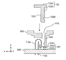
- 4A and 4B are cross-sectional views schematically showing an example of a part of the controller 100 provided in the control device 10 according to the first embodiment.
- FIG. 4A and 4B are cross-sectional views taken along the line IVb-IVb shown in FIG.
- FIG. 4A shows a state before the label body 120 (label body 122 in the example shown in FIG. 4A) is attached to the controller 100 (housing 900)
- FIG. 4B shows the state shown in FIG. 4 shows a state in which the label body 120 (in the example shown in FIG. 4B, the label body 122) is attached to the controller 100 (housing 900).
- the movable contact 112a and the fixed contact 112b do not contact each other.
- the plurality of (for example, four) switches 110AB included in the function switch unit 112 are all in an open state in an initial state (a state in which the label body 122 is not attached to the housing 900).
- the protrusion 122b is inserted into the hole 910 of the casing 900 in the negative y-axis direction, as shown in FIG. 4A. It is attached to the housing 900).
- the projecting portion 122b causes the movable contact 112a to be moved by the rib 122c provided on the side surface of the projecting portion 122b.
- the movable part of the movable contact 112a is displaced by pressing in a direction substantially perpendicular to the insertion direction of the protrusion 122b (the direction indicated by the solid line arrow in FIG. 4B, the positive x-axis direction).
- the switch 110AB constituted by the movable contact 112a and the fixed contact 112b is in a closed state.
- the label body 122 is attached to the controller 100 (housing 900)
- the area where the rib 122c is not provided in the protrusion 122b does not press the movable contact 112a.
- 110AB remains open. Therefore, in the example shown in FIG. 3A, when the label body 122 is attached to the controller 100 (housing 900), the four switches 110AB included in the function switch unit 112 are negative on the z-axis in the figure. In order, the direction is open, closed, open, and closed.
- the size of the rib 122c provided on the protrusion 122b is set so that the amount by which the movable part of the movable contact 112a is displaced when the rib 122c is pressed is within the elastic range of the movable contact 112a. Has been. Therefore, when the label body 122 is removed from the controller 100 (housing 900), the movable portion of the movable contact 112a pressed by the protrusion 122b returns to its original position by its own elastic force. As a result, the switch 110AB in the closed state returns to the open state. In other words, when the label body 122 is removed from the controller 100 (housing 900), the four switches 110AB included in the function switch unit 112 return to the initial state.
- the shape of the protrusion 120b of the label body 120 refers to the protrusion of the arbitrary label body 120
- the rib 120c provided on the protrusion 120b the shape of the protrusion 120b of the label body 120.
- the movable part of the movable contact 112a is displaced according to the number and the arrangement position.
- the concave portion 122d provided on the side surface (opposite side) of the protruding portion 122b opposite to the side surface on which the rib 122c is provided includes the protruding portion 950 included in the housing 900 and the protruding portion 122b. It is a fitting part fitted in the direction (x-axis direction) perpendicular
- the label body 122 is prevented from moving and dropping off in the direction opposite to the insertion direction when the posture of the controller 100 is changed. That is, the fitting portion (for example, the recess 122d) is formed in the casing 900 in a direction perpendicular to the insertion direction of the label body 120 when the label body 120 is attached to the controller 100 (housing 900). The label body 120 is stabilized at each mounting position by fitting with the (projection 950).
- the protrusion 120b (for example, the protrusion 122b) of the label body 120 (for example, the label body 122) has a protrusion 120b when the label body 120 is attached to the controller 100 (housing 900).
- the rib 120c (for example, rib 122c) provided on the movable member 110a (for example, the movable contact 112a) of each switch 110AB disposed at a position corresponding to the attachment position of the label body 120 in a predetermined direction. Press to displace. Then, depending on the number and arrangement positions of the ribs 120c provided on the protrusion 120b, the open / closed states of the switches 110AB included in the function switch unit 110 (for example, the function switch unit 112) at the mounting position.
- label body 120 for example, label body 121, label body 123, label body 124, etc.
- label body 122 the number of ribs 120c provided on the side surfaces of projections 120b of each label body 120
- the combination of the open / closed states of the plurality of switches 110AB included in the function switch unit 110 arranged at a position corresponding to the attachment position of the label body 120 is determined by the arrangement position.
- FIG. 5 is a block diagram showing an example of the configuration of the controller 100 in the first embodiment.
- the controller 100 includes a key 500 (only the keys 501 to 504 are shown in FIG. 5), a label body 120 (only the label body 121 and the label body 122 are shown in FIG. 5), and a function switch unit 110 (see FIG. 5). Only the function switch units 111 and 112 are shown), a microcomputer 600, a memory 700, and an output unit 300.
- this correspondence is defined as follows.
- a certain function switch unit 110 In response to a user operation (for example, pressing) on a certain key 500, a certain function switch unit 110 outputs a signal and participates in determining an operation (function assigned to the key 500) to be executed by the electric device.
- the function switch unit 110 and the key 500 correspond to each other.
- the protrusion 121b and the protrusion 122b are not shown.
- components that are necessary for the operation of the controller 100 such as a power source are not shown for those that are not necessary for the description of the controller of the present disclosure.
- the label body 121 is attached to a predetermined position (a position corresponding to the key 501) of the housing 900. Then, the combination of the open / close states of the switch 110AB included in the function switch unit 110 (function switch unit 111) corresponding to the key 501 is set by the protrusion 121b of the label body 121.
- each switch 110AB included in the function switch unit 111 is set to a combination in which the switch 110AB shown in the uppermost stage in the drawing is closed and the other switches 110AB are opened by the label body 121. Has been.
- the label body 122 is attached to a predetermined position (position corresponding to the key 502) different from the attachment position of the label body 121 of the housing 900. Then, the combination of the open / close states of the switch 110AB included in the function switch unit 110 (function switch unit 112) corresponding to the key 502 is set by the protrusion 122b of the label body 122.
- each switch 110AB included in the function switch unit 112 has a label body 122 in which the second and fourth switches 110AB from the top are closed and the other switches 110AB are open. It is set to a certain combination.
- Each of the switches 110AB included in the function switch unit 110 has one end grounded and the other end connected to the microcomputer 600. In each switch 110AB, the potential on the microcomputer 600 side is changed by switching between the open state and the closed state.
- the microcomputer 600 is connected to the key 500 and each switch 110AB.
- the microcomputer 600 detects this operation.
- each open / close state of the switch 110AB included in the function switch unit 110 corresponding to the operated key 500 is acquired based on the potential. In this way, the microcomputer 600 detects the combination of the open / close states of these switches 110AB.
- a memory 700 is connected to the microcomputer 600.
- combinations of the open / closed states of the switch 110AB and various codes for causing the electric device to be controlled to execute various operations are stored in association with each other.
- the microcomputer 600 acquires a code associated with the detected combination of the open / closed states of the switch 110AB from the memory 700.
- the memory 700 has a combination of a plurality of switches 110AB (for example, four switches 110AB) included in one function switch unit 110 and a predetermined operation for an electric device to be controlled.
- switches 110AB for example, four switches 110AB
- 0 in the left column indicates that the switch 110AB is open
- “1” indicates that the switch 110AB is closed.
- a four-digit number in which four numbers are arranged indicates one combination of open / close states of the four switches 110AB.
- a four-digit number and a code which are associated with each other and indicate a combination of open / close states, are stored in the same row.
- “0” may indicate a closed state
- “1” may indicate an open state.
- the memory 700 is an example of a storage unit according to the present disclosure, and can be realized by using, for example, a semiconductor memory.
- the output unit 300 includes an infrared light emitting diode.
- the microcomputer 600 is also connected to the output unit 300. Then, the microcomputer 600 causes the output unit 300 to output a signal indicating the code acquired from the memory 700 (for example, an infrared signal).
- the microcomputer 600 is an example of a control unit in the present disclosure.
- the switch 110AB is closed by being pressed by the protruding portion 120b of the label body 120 attached to the controller 100 (housing 900).
- the configuration is not limited to this.
- the switch 110AB may be switched between the open and closed states by being pressed by the protrusion 120b. That is, the initial state is a closed state, and a switch configured to be opened by being pressed by the protrusion 120b of the label body 120 attached to the controller 100 (housing 900) is used as the switch 110AB. Also good.
- the label body 122 is attached to the attachment position (position corresponding to the key 502) shown in the drawing referred to in the above description.
- the combination of the open / closed states of the four switches 110AB included in the function switch unit 112 corresponding to the key 502 is set by the label body 122 attached to the attachment position.
- This combination is "open state (0) -closed state (1) -open state (0) -closed state (1)" in the negative direction in the z-axis in the figure (see FIG. 3A).
- a display of “voice switching” is attached to the surface of the display unit 122a of the label body 122.
- the user corresponds to the label body 122 on which “audio switching” is displayed in order to switch the audio of the bilingual broadcast program being viewed on the television receiver. Assume that the key 502 is pressed.
- the microcomputer 600 detects that the key 502 has been pressed. In response to this detection, the microcomputer 600 detects a combination of the open / closed states of the four switches 110AB included in the function switch unit 112 corresponding to the key 502.
- the combination of the open / close states is “open state (0) ⁇ closed state (1) ⁇ open state (0) ⁇ closed state (1)”.
- the microcomputer 600 accesses the memory 700 in order to obtain a code associated with this combination of open / close states.
- the microcomputer 600 reads the above combination as “0101”, and acquires the code “0x40, 0x04, 0x01, 0x00, 0xA8, 0xA9” associated therewith from the memory 700 (see Table 1).
- the microcomputer 600 controls the output unit 300 so that a signal indicating the acquired code is transmitted from the output unit 300.
- the output unit 300 outputs a signal indicating this code.
- the television receiver that has received the signal output from the output unit 300 switches the sound output from the main sound to the sub sound or from the sub sound to the main sound based on the signal.
- a function attached to the label body 120 (for example, the label body 122) in response to a user operation (pressing) on the key 500 (for example, the key 502).
- a signal corresponding to (for example, voice switching) is transmitted from the control device 10 to an electric device to be controlled (for example, a television receiver).
- the electric equipment for example, television receiver
- the electric equipment which received the signal performs operation (for example, voice switching) which a user desires.
- the key 501 corresponds to the label body 121, and the combination of the open / close states of the four switches 110AB included in the function switch unit 111 corresponding to the key 501 is In the z-axis in the figure, in the negative direction, “closed state (1) ⁇ open state (0) ⁇ open state (0) ⁇ open state (0)”. (See FIG. 3A).
- the combination of the open / closed states of the four switches 110AB included in the function switch unit 112 corresponding to the key 502 is “closed” in the negative direction in the z-axis in the figure.
- the user presses the key 502 corresponding to the label body 121 on which “Internet” is displayed in order to search the Internet for information related to the program being viewed by the television receiver. Assume that the button is pressed.
- the microcomputer 600 detects that the key 502 has been pressed. In response to this detection, the microcomputer 600 detects a combination of the open / closed states of the four switches 110AB included in the function switch unit 112 corresponding to the key 502.
- the combination of the open and closed states is “closed state (1) ⁇ open state (0) ⁇ open state (0) ⁇ open state (0)”.
- the microcomputer 600 accesses the memory 700 in order to obtain a code associated with this combination of open / close states.
- the microcomputer 600 reads the above combination as “1000”, and acquires the code “0x40, 0x04, 0x01, 0x00, 0xE8, 0xE9” associated therewith from the memory 700 (see Table 1).
- the microcomputer 600 controls the output unit 300 so that a signal indicating the acquired code is transmitted from the output unit 300.
- the output unit 300 outputs a signal indicating this code.
- the television receiver that has received the signal output from the output unit 300 generates a small screen based on the signal, displays the television broadcast on the small screen, starts the web browser, and displays the web browser on the parent screen. To do.
- the user changes the assignment of the function to the key 500 only by replacing the label body 120 (for example, replacing the label body 121 and the label body 122) (
- the assignment of the function to the key 502 can be changed from “voice switching” to “display internet connection screen”.
- the controller is a controller for controlling an electric device, and outputs at least a part for outputting a signal for causing the electric device to perform a predetermined operation.
- a label body attached in a state where the projection is inserted into the hole of the housing and the display portion is outside the housing.
- the projection part of a label body determines the combination of each opening / closing state of the some switch switched by pressing and displacing at least one part of the contact of a some switch to a predetermined direction.
- the predetermined operation is determined according to the combination.
- controller 100 is an example of a controller.
- a television receiver is an example of an electrical device.
- the key 500 is an example of an operation unit.
- the output unit 300 is an example of an output unit.
- the movable contact 110a is an example of a contact.
- the switch 110AB is an example of a switch that switches between open and closed states.
- the function switch unit 110 is an example of a function switch unit.
- the display unit 120a is an example of a display unit.
- the protrusion 120b is an example of a protrusion.
- the housing 900 is an example of a housing.
- the hole 910 is an example of a hole.
- the label body 120 is an example of a label body.
- the controller 100 for controlling an electric device includes a key 500, an output unit 300, a function switch unit 110, and a label body 120. .
- the key 500 is operated (for example, pressed) by the user.
- the output unit 300 outputs a signal for causing an electric device (for example, a television receiver) to execute a predetermined operation in response to a user operation (for example, pressing) to the operation unit.
- an electric device for example, a television receiver
- a user operation for example, pressing
- the function switch unit 110 has a movable contact 110a that is at least partially elastically displaceable in a predetermined direction, and the open / close state is switched when at least a part of the movable contact 110a is displaced in the predetermined direction.
- a plurality of switches 110AB are included.
- the label body 120 includes a display portion 120a and a protrusion portion 120b protruding from the display portion 120a.
- the protrusion portion 120b is inserted into a hole 910 provided in the housing 900 of the controller 100, and the display portion 120a is disposed outside the housing 900. It is attached to the controller 100 (casing 900) in the state of being.
- the protrusion 120b of the label body 120 moves the movable part, which is at least a part of the movable contacts 110a of the plurality of switches 110AB, in a predetermined direction (for example, the combination of the open / closed states of the plurality of switches 110AB that are switched by being pressed and displaced in the positive x-axis direction is determined.
- a predetermined operation of the electric device for example, “voice switching”, “display of Internet connection screen”, etc. is determined according to this combination.
- control device for example, the control device 100
- the user simply replaces a plurality of label bodies (for example, the label body 120) with each other, and functions to the operation unit (for example, the key 500).
- the assignment can be changed.
- the predetermined direction may be substantially perpendicular to the direction in which the protrusion is inserted, and the protrusion is configured to dispose at least a part of the contact when the label body is attached to the controller. You may press and displace in parts other than a front-end
- the predetermined direction is substantially perpendicular to the insertion direction of the protrusion 120b.
- the protruding portion 120b presses the movable portion of the movable contact 110a with a portion (for example, a side surface) other than the tip, The movable part is displaced.
- the controller further includes an operation unit, a control unit electrically connected to the operation unit, the plurality of switches, and the output unit, and a storage unit connected to the control unit.
- the storage unit may store a combination of the open / closed state and a code for causing the electric device to execute a predetermined operation in association with each other.
- the control unit detects a combination of each open / close state of the plurality of switches, acquires a code associated with the detected open / close state combination from the storage unit, and outputs the acquired code You may make it output to a part as a signal.
- the key 500 is an example of an operation unit.
- the microcomputer 600 is a part of the control unit.
- the memory 700 is a part of the storage unit.
- the controller 100 includes a key 500, a microcomputer 600 electrically connected to the key 500, the plurality of function switch units 110, and the output unit 300, and the microcomputer 600. And a memory 700 connected to the.
- the memory 700 stores a combination of open / closed states of the plurality of switches 110AB and a code for causing an electric device (for example, a television receiver) to execute a predetermined operation in association with each other.
- the microcomputer 600 When the microcomputer 600 detects a user operation (pressing) on the key 500, the microcomputer 600 detects a combination of the open / close states of the plurality of switches 110AB included in the function switch unit 110 corresponding to the key 500, and detects the detected open / close state. The code associated with the combination is acquired from the memory 700. Then, the microcomputer 600 causes the output unit 300 to output the acquired code as a signal.
- control device for example, the control device 100
- the user simply replaces a plurality of label bodies (for example, the label body 120) with each other, and functions to the operation unit (for example, the key 500).
- the assignment can be changed.
- a display indicating a predetermined operation is attached to the display unit 120a.
- the user can change the assignment of the function to the key 500 by attaching the label body 120 selected by looking at the display on the display unit 120a to the controller 100 (housing 900). That is, the user who uses the controller 100 changes the display of the key 500 by himself / herself according to the customization of the function of the controller 100, or changes the setting to the controller 100 or the electric device according to the display of the key 500. The convenience of the user can be improved.
- the configuration of the controller 1100 in this modification is substantially the same as the configuration of the controller 100 described in the first embodiment. That is, in the controller 1100 in the present modification, the configuration in which the function assignment to the operation unit can be easily changed by replacing the label body is substantially the same as the controller 100 of the first embodiment. In the following, this modification will be described focusing on differences from the first embodiment.
- the controller 1100 in this modification further includes an insertion detection switch that detects whether or not the label body 120 is attached to the controller.
- the controller 1100 in this modification is different from the controller 100 described in the first embodiment in this respect.
- FIG. 6 is an exploded perspective view schematically showing an example of a part of the controller 1100 included in the control device 10 according to the first modification of the first embodiment.
- FIG. 6 shows an exploded perspective view seen from substantially the same direction as the exploded perspective view shown in FIG. 3B.
- FIG. 6 shows the insertion detection switch cover 201c to the insertion detection switch cover 204c included in the controller 1100 in addition to the components of the controller 100 shown in FIG. 3B in the first embodiment.
- the insertion detection switch cover 201c to the insertion detection switch cover 204c are collectively referred to as an insertion detection switch cover 200c without any particular distinction.
- the insertion detection switch cover 200c is formed by molding an insulating elastic body (for example, silicon rubber).
- the insertion detection switch 201 to the insertion detection switch 204 are provided on the substrate 800 under each insertion detection switch cover 200c.
- the insertion detection switch 201 to the insertion detection switch 204 are collectively referred to as the insertion detection switch 200 without any particular distinction.
- the insertion detection switch 200 is a switch whose open / close state is switched by being pressed by the label body 120 attached to the controller 1100 (housing 900) and at least partially displaced.
- the insertion detection switch 200 has a fixed contact formed by attaching a metal plate to the substrate 800 directly below the insertion detection switch cover 200c, and a surface of the insertion detection switch cover 200c shown in FIG.
- the switch may be configured to include a movable contact formed by a metal leaf spring having a generally extending shape.
- the movable contact 200a is displaced at least partially in the direction of the substrate 800 when a force is applied from the label body 120 attached to the controller 1100 (housing 900) in the insertion direction of the label body 120. In contact with the stationary contact 200b.
- the displaced part is also referred to as a movable part.
- the movable contacts 200a of the insertion detection switch 201 to the insertion detection switch 204 are also referred to as the movable contact 201a to the movable contact 204a, respectively.
- the fixed contacts 200b of the insertion detection switch 201 to the insertion detection switch 204 are also referred to as fixed contact 201b to fixed contact 204b, respectively.
- the insertion detection switch 200 When the label body 120 made of ABS resin and the movable contact 200a that is a metal plate are in direct contact with each other, the insertion detection switch 200 may be damaged or worn when the label body 120 is attached or detached.
- the insertion detection switch cover 200c prevents such damage and wear, and suppresses the influence on the insertion detection switch 200 due to static electricity from the outside of the housing 900 (for example, static electricity accumulated in the user). be able to.
- 7A and 7B are cross-sectional views schematically showing an example of a part of the controller 1100 provided in the control device 10 in the first modification of the first embodiment.
- FIGS. 7A and 7B show a state before the label body 120 (label body 122 in the example shown in FIG. 7A) is attached to the controller 1100 (housing 900), as in FIG. 4A, and FIG. Similar to FIG. 4B, the label body 120 (label body 122 in the example shown in FIG. 7B) is shown attached to the controller 1100 (housing 900).
- FIG. 7A and 7B show an insertion detection switch 202 as an example of the insertion detection switch 200.
- the movable contact 202a is disposed below the insertion detection switch cover 202c
- the fixed contact 202b is disposed on the substrate 800 under the movable contact 202a.
- the movable contact 202a and the fixed contact 202b do not contact each other as shown in FIG. 7A.
- the insertion detection switch 202 is in an open state in an initial state (a state in which the label body 122 is not attached to the housing 900).
- the protrusion 122b is inserted into the hole 910 of the housing 900 in the negative y-axis direction, as shown by a dashed arrow in FIG. 7A, so that the controller 1100 ( It is attached to the housing 900).
- the protrusion 122b presses the movable contact 112a by the rib 122c provided on the side surface, The movable part of the movable contact 112a is displaced. Furthermore, in this modification, the protrusion 122b presses the insertion detection switch cover 202c in the insertion direction at the tip portion, and displaces the insertion detection switch cover 202c in the insertion direction. Further, the movable contact 202a of the insertion detection switch 202 is pressed in the insertion direction of the projection 122b via the insertion detection switch cover 202c to displace the movable portion of the movable contact 202a. . As a result of this displacement, the movable contact 202a and the fixed contact 202b come into contact with each other. In other words, the insertion detection switch 202 is closed.
- the amount by which the movable part of the movable contactor 202a is displaced when the projection 122b is pressed is set to be within the elastic range of the movable contactor 202a. Therefore, when the label body 122 is removed from the controller 1100 (housing 900), the movable portion of the movable contactor 202a that has been pressed by the protrusion 122b returns to its original position due to its own elastic force. Thereby, the insertion detection switch 202 in the closed state returns to the open state. In other words, when the label body 122 is removed from the controller 1100 (housing 900), the insertion detection switch 202 returns to the initial state. Thereafter, when any one of the label bodies 120 is attached to this attachment position, the movable portion of the movable contactor 202a is displaced again by being pressed by the protruding portion of the label body 120.
- the controller 1100 has, for example, the following:
- the microcomputer 600 can detect whether the label body 120 is attached to each attachment position.
- FIG. 8 is a block diagram showing a configuration example of the controller 1100 in the first modification of the first embodiment.
- the controller 1100 includes a key 500 (only the keys 501 to 504 are shown in FIG. 8), a label body 120 (only the label body 121 and the label body 122 are shown in FIG. 8), and a function switch unit 110 (shown in FIG. 8). Includes only the function switch unit 111 and the function switch unit 112), the insertion detection switch 201 and the insertion detection switch 202, the microcomputer 600, the memory 700, and the output unit 300.
- the insertion detection switch 201 is substantially the same as the insertion detection switch 202 and corresponds to the key 501.
- the definition of the correspondence between the function switch unit 110 and the key 500 is the same as in the first embodiment.
- the correspondence between the insertion detection switch 200 and the key 500 is defined as follows. When the function of a certain key 500 is determined by the label body 120 appropriately attached to a certain attachment position, the insertion detection switch 200 for detecting whether or not the label body 120 is attached to that attachment position is Corresponding to 500.
- the protrusion 121b and the protrusion 122b are not shown. Further, even components that are necessary for the operation of the controller 1100 such as a power source are not shown for those that are not necessary for the description of the controller of the present disclosure.
- the insertion detection switch 200 has one end grounded and the other end connected to the microcomputer 600. In each insertion detection switch 200, the potential on the microcomputer 600 side is changed by switching between the open state and the closed state. Thereby, the microcomputer 600 detects the open / closed state of the insertion detection switch 200.
- the configuration in which the insertion detection switch 200 is closed by being pressed by the protrusion 120b of the label body 120 attached to the controller 1100 (housing 900) has been described.
- the configuration of the insertion detection switch 200 is not limited to this.
- the insertion detection switch 200 may be switched between being opened and closed by being pressed by the protrusion 120b of the label body 120 that is appropriately attached.
- the initial state is a closed state
- a switch configured to be opened by being pressed by the protrusion 120b of the label body 120 attached to the controller 1100 (housing 900) is used as the insertion detection switch 200. May be.
- the microcomputer 600 detects that the key 500 has been operated, and the open / closed state of the insertion detection switch 200 corresponding to the operated key 500 is described above. As described above, detection is performed based on the potential.
- the microcomputer 600 displays the key
- the output unit 300 outputs a signal indicating a predetermined code (a code corresponding to the user-operated key 500) by the operation described in the first embodiment.
- the microcomputer 600 moves to the key 500.
- an operation for causing the output unit 300 to output a signal indicating a predetermined code (a code corresponding to the key 500 operated by the user) is not executed.
- the controller is an insertion detection that is a switch that is switched between an open state and a closed state by being displaced by at least a part of the operation unit and the projection. And a switch.
- the output unit may output a signal for causing the electric device to execute a predetermined operation in response to the operation of the operation unit when the insertion detection switch is in one of the open state and the closed state. In the other state of the open state and the closed state, it is not necessary to output a signal in response to the operation of the operation unit.
- the key 500 is an example of an operation unit.
- the controller 1100 is a part of the controller.
- the insertion detection switch 200 is a part of the insertion detection switch.
- the controller 1100 is further attached to the controller 1100 (housing 900) in addition to the configuration of the controller 100 shown in the first embodiment.
- An insertion detection switch 200 is provided that switches between an open state and a closed state when at least a part of the label body 120 is pressed by the protrusion 120b of the label body 120.
- the output unit 300 when the insertion detection switch 200 is in a closed state, for example, in response to a user operation on the key 500, the output unit 300 outputs a signal for causing the electrical device to be controlled to execute a predetermined operation. To do. On the other hand, the output unit 300 does not output a signal in response to a user operation on the key 500 when the insertion detection switch 200 is in an open state, for example.
- the controller does not include the insertion detection switch 200 is assumed. It is assumed that some code is associated with a combination of open / closed states (for example, “0000”) in which all the switches 110AB included in one function switch unit 110 are in the initial state. In such a case, even if the label body 120 is not attached to the attachment position of the casing 900, when the key 500 corresponding to the attachment position is operated (pressed) by the user, the microcomputer 600 performs the user operation. In response, the output unit 300 outputs a signal indicating the code.
- some code is associated with a combination of open / closed states (for example, “0000”) in which all the switches 110AB included in one function switch unit 110 are in the initial state.
- the microcomputer 600 performs the user operation.
- the output unit 300 outputs a signal indicating the code.
- the microcomputer 600 responds to a user operation (pressing) on the key 500 only when the label body 120 is appropriately attached at the attachment position.
- a signal indicating a code corresponding to is output from the output unit 300.
- a combination of open / closed states in which all of the switches 110AB are in an initial state for example, “0000” in order to prevent the electric device from being erroneously controlled. It is also assumed that no code is associated with. However, in the controller 1100 including the insertion detection switch 200, a code can be associated with a combination of open / close states (for example, “0000”) in which all the switches 110AB are in the initial state. Therefore, in the configuration shown in the present modification, it is possible to increase the choices of functions that can be assigned to the key 500 by the user.
- the configuration of the controller 2100 in the present modification is substantially the same as the configuration of the controller 100 described in the first embodiment. That is, in the controller 2100 in the present modification, the configuration in which the function assignment to the operation unit can be easily changed by replacing the label body is substantially the same as the controller 100 of the first embodiment. In the following, this modification will be described focusing on differences from the first embodiment.
- the controller 2100 in the present modified example further functions by static electricity from the outside of the casing 900 (for example, static electricity accumulated in the user).
- An insulating member that suppresses the influence on the switch unit 110 is provided.
- the controller 2100 in this modification is different from the controller 100 described in the first embodiment in this respect.
- FIG. 9 is an exploded perspective view schematically showing an example of a part of the controller 2100 provided in the control device 10 according to the second modification of the first embodiment.
- FIG. 9 shows an exploded perspective view seen from substantially the same direction as the exploded perspective view shown in FIG. 3B.
- FIG. 9 shows a rubber cap 400a and a housing 400b included in the controller 2100 in addition to the components of the controller 100 shown in FIG. 3B in the first embodiment.
- the rubber cap 400a is formed by molding an insulating elastic body (for example, silicon rubber). Rubber cap 400a is an example of the 1st insulating member in this modification.
- the housing 400b is formed by molding an insulating resin (for example, polypropylene or the like).
- the housing 400b is an example of a second insulating member in this modification.
- the rubber cap 400a and the housing 400b are collectively referred to as an insulating member 400.
- FIG. 10 is a transparent perspective view schematically showing an example of a part of the controller provided in the control device 10 in the second modification of the first embodiment.
- FIG. 10 is a transparent perspective view of a part that insulates the function switch unit 110 of the controller 2100 in the assembled state from the surroundings, and shows the inside of the rubber cap 400a through the rubber cap 400a.
- the rubber cap 400a is put on a switch 110AB configured to include a movable contact 110a and a fixed contact 110b.
- the rubber cap 400a covers the switch 110AB so that the protrusion 120b of the label body 120 attached to the controller 2100 does not directly contact the switch 110AB.
- the label body 120 and the function switch unit 110 are electrically insulated.
- the housing 400b has a plurality of walls that enter the gaps between the movable contacts 110a adjacent to each other (see FIG. 9), and these walls electrically connect the switches 110AB adjacent to each other. Separated.
- FIG. 11A and FIG. 11B are cross-sectional views schematically showing an example of a part of the controller 2100 provided in the control device 10 according to the second modification of the first embodiment.
- FIG. 11A shows a state before the label body 120 (label body 122 in the example shown in FIG. 11A) is attached to the controller 2100 (housing 900), as in FIG. 4A. Similar to FIG. 4B, the label body 120 (label body 122 in the example shown in FIG. 11B) is shown attached to the controller 2100 (housing 900).
- the label body 122 is inserted into the hole 910 of the casing 900 in the negative y-axis direction so that the controller 2100 (the casing 900).
- the rubber cap 400a is moved by the rib 122c of the protrusion 122b of the label body 122 as shown by the solid line arrow in FIG. Pressed in the direction. Since the rubber cap 400a is formed of an elastic body such as silicon rubber as described above, at least a part of the rubber cap 400a is displaced by this pressing. That is, as shown in FIG. 11B, the rib 122c of the protrusion 122b can displace a partial region of the rubber cap 400a, and the movable contact 112a in the x-axis positive direction with the rubber cap 400a interposed therebetween. Can be pressed. As a result, in the switch 110AB, the movable part of the movable contact 112a is displaced in the direction indicated by the solid line arrow in FIG. 11B (the positive x-axis direction) and contacts the fixed contact 112b.
- the switch 110AB is set to the open state or the closed state depending on the presence or absence of the rib 122c even after the rubber cap 400a is attached, as in the first embodiment. Furthermore, since the switch 110AB is electrically separated from the label body 122 and the housing 900 by the insulating rubber cap 400a, in this modification, the influence on the controller 2100 due to external static electricity is suppressed. .
- the rib 122c provided in the projection part 122b is set so that the displacement of the rubber cap 400a is within the elastic range of the rubber cap 400a. Therefore, when the label body 122 is removed from the controller 2100 (housing 900), the displacement region of the rubber cap 400a by the rib 122c returns to the original position by its own elastic force. And as demonstrated in Embodiment 1, the movable part of the movable contact 112a also returns to the original position.
- the portion of the rubber cap 400a that is displaced by being pressed by the rib 122c provided on the protrusion 122b includes not only the portion that contacts the rib 122c but also the peripheral portion of the portion that contacts the rib 122c. Therefore, there is a possibility that the movable contact 112a disposed at a position corresponding to the region where the rib 122c of the protrusion 122b is not provided is erroneously pressed by the peripheral portion that is displaced.
- the housing 400b is provided to prevent such a phenomenon from occurring.
- FIG. 11C is a cross-sectional view schematically showing an example of a part of the controller provided in the control device 10 in the second modification of the first embodiment.
- FIG. 11C is a cross-sectional view taken along the line XIc-XIc in FIG. 11B and shows a part of the cross section of the controller 2100 in an assembled state.
- a gap between adjacent movable contacts 110a (in the example shown in FIG. 11C, a gap between adjacent movable contacts 112a, and a gap between adjacent movable contacts 112a and 113a).
- the wall of the housing 400b is arranged.
- the wall of the housing 400b electrically separates adjacent switches 110AB.
- the fixed contact 110b is disposed in a slit (see FIG. 9) provided on the wall of the housing 400b.
- the shape of the fixed contact 110b is not limited to the illustrated shape example, and may be, for example, a shape separated from the wall of the housing 400b, like the movable contact 110a.
- the contacts of the switches 110AB adjacent to each other are electrically separated by the wall of the housing 400b.
- the housing 400b is expressed as electrically separating the switches 110AB adjacent to each other.
- the two ribs 122c of the protrusion 122b of the label body 122 attached to the controller 2100 press the rubber cap 400a in the x-axis positive direction (the direction of the solid arrow in FIG. 11C). is doing.
- the movable contactor 112a disposed at a position corresponding to the rib 122c is displaced in the positive x-axis direction together with the displacement of the rubber cap 400a by being pressed against the rib 122c with the rubber cap 400a interposed therebetween. Thereby, this movable contact 112a contacts the fixed contact 112b.
- the movable contact 112a pressed by the rib 122c of the protrusion 122b is only the movable contact 112a arranged at a position corresponding to the rib 122c, and the rib 122c is not provided. It is possible to prevent the movable contact 112a arranged at a position corresponding to the above from being accidentally pressed. Therefore, in the controller 2100, the combination of the open / closed states of the switches 110AB included in each function switch unit 110 is appropriately set according to the rib 122c provided on the protrusion 122b.
- the housing 400b has a relatively short distance between adjacent switches 100AB, and a displacement of a part of the rubber cap 400a by the rib 122c is arranged at a position corresponding to a region where the rib 122c is not provided. This is effective in a controller that may accidentally press the movable contact 112a.
- the distance between adjacent switches 100AB is relatively long, and the displacement of a part of the rubber cap 400a by the rib 122c causes the movable contact 112a disposed at a position corresponding to the region where the rib 122c is not provided.
- the controller that has a low possibility of being accidentally pressed may not include the housing 400b.
- the controller may further include a first insulating member that electrically insulates between the label body and the function switch unit. Then, the first insulating member may be pressed by the protruding portion, and at least a part of the region may be elastically displaced in a predetermined direction. The protrusion may displace at least a part of the first insulating member to press and displace at least one contact of the plurality of switches in a predetermined direction.
- the controller 2100 is an example of a controller.
- the rubber cap 400a is an example of a first insulating member.
- the controller 2100 is further provided between the label body 120 and the function switch unit 110 in addition to the configuration of the controller 100 shown in the first embodiment. It has a rubber cap 400a that electrically insulates.
- the rubber cap 400a is pressed by the rib 120c of the protrusion 120b, and at least a part of the region is elastically displaced in a predetermined direction (for example, the positive x-axis direction).
- the rib 120c included in the protrusion 122b displaces at least a part of the rubber cap 400a, thereby pressing the at least one movable contact 110a of the plurality of switches 110AB included in the function switch unit 110 to obtain a predetermined amount. It is displaced in the direction (for example, the positive x-axis direction).
- the switch 110AB is electrically separated from the label body 122 and the housing 900 by the insulating rubber cap 400a, so that static electricity from the outside (for example, static electricity accumulated in the user, Etc.) is suppressed on the controller 2100.
- the controller may further include a second insulating member that separates the plurality of switches.
- the second insulating member is a size of a region of the first insulating member that is displaced by being pressed by the protruding portion by pushing back the first insulating member pressed by the protruding portion with a force in a direction opposite to a predetermined direction. May be restricted.
- the housing 400b is an example of a second insulating member.
- the controller 2100 further includes a housing 400b that separates the plurality of switches 110AB.
- the housing 400b pushes back the rubber cap 400a pressed against the rib 120c of the protrusion 120b with a force in a direction (for example, the x-axis negative direction) opposite to a predetermined direction (for example, the x-axis positive direction).
- the size of the region that is displaced by being pressed by the rib 120c is limited.
- the movable contact 110a pressed by the rib 120c of the protrusion 120b is limited to the movable contact 110a disposed at a position corresponding to the rib 120c, and the rib 120c is not provided.
- the movable contact 110a arranged at a position corresponding to the region is prevented from being accidentally pressed by a partial region of the displaced rubber cap 400a. Therefore, in the controller 2100, the combination of the open / closed states of the switches 110AB included in each function switch unit 110 is appropriately set according to the rib 120c provided on the protrusion 120b.
- the controller in the present embodiment includes a function switch unit having a configuration different from that of the function switch unit 110 included in the controller illustrated in the first embodiment and each modification of the first embodiment.
- other configurations of the controller of the present embodiment are substantially the same as those of the controller shown in the first embodiment or each modification of the first embodiment.
- the present embodiment will be described focusing on differences from the function switch unit 110 shown in the first embodiment.
- the external appearance of the control device in the present embodiment is substantially the same as that of the control device 100 shown in the first embodiment, description thereof is omitted.
- FIG. 12 is a perspective view schematically showing an example of the function switch unit 1110 provided in the controller according to the second embodiment.
- FIG. 12 shows one function switch unit 1110, but one function switch unit 1110 functionally corresponds to one function switch unit 110 shown in the first embodiment. . Therefore, in the controller shown in the second embodiment, one function switch unit 1110 is basically assigned to one operation unit such as a key to which a function is assigned.
- the function switch unit 1110 includes a plurality of (for example, four) movable contacts 1110a.
- the movable contacts 110a included in one function switch unit 110 are arranged on the substrate 800 in a one-dimensional manner along the z-axis direction in the same posture. It had been.
- the movable contact 1110a in the present embodiment includes a plurality of types (for example, two types) of postures, and is arranged two-dimensionally along the xz plane on the substrate 800. .
- the direction of displacement of the movable part of the movable contactor 1110a is the y-axis direction shown in FIG. 12, which is the same as the label body insertion direction.
- the function switch unit 1110 is different from the function switch unit 110 shown in the first embodiment in these points.
- the fixed contacts 1110b are different from the fixed contacts 110b included in the function switch unit 110 shown in Embodiment 1 on the substrate 800. This is realized as a land of a wiring pattern.
- the fixed contact 1110b may not be included in the function switch unit 1110.
- a land for soldering the wiring pattern on the substrate or a part of the wiring connected to other components or the like may be used as the fixed contact 1110b.
- one movable contact 1110a and one fixed contact 1110b arranged at a position corresponding to the movable contact 1110a are paired, and one switch that switches between open and closed states. Is formed. This is the same as in the first embodiment.
- the label body has a configuration suitable for mutating the movable part of the movable contactor 1110a when attached to the controller. This configuration is different from the label body 120 shown in the first configuration.
- the label body in the present embodiment includes a display unit and a protrusion protruding from the display unit, and is configured to be attached to the housing 900 so that a part (surface) of the display unit is exposed.
- the protruding portion in the present embodiment is not configured to press the movable portion with a rib that stands vertically with respect to the inserting direction of the protruding portion as shown in the first embodiment, but by the tip portion of the protruding portion.
- the movable part is configured to press in the same direction as the insertion direction of the protrusion.
- the protrusion has a predetermined length (movable contact 1110a) at a position corresponding to the movable contact 1110a when attached to the housing 900 on the back surface of the display portion of the label body.
- the length can be appropriately pressed).
- the controller shown in the present embodiment has the configuration of the function switch unit and the configuration of the label body that determines the combination of the open / close states of the plurality of switches included in the function switch unit, as shown in the first embodiment.
- the other configurations as the controller are substantially the same in the first embodiment and the second embodiment. Therefore, the block diagram showing an example of the configuration of the controller 100 shown in FIG. 5 in the first embodiment can also be applied to this embodiment. Therefore, in the present embodiment, description regarding the configuration of the controller is omitted.
- FIGS. 13A and 13B are cross-sectional views schematically showing an example of a part of a controller provided in the control device according to the second embodiment.
- 13A and 13B are cross-sectional views of the controller as shown in FIG. 1A or FIG. 1B, taken along the xy plane between adjacent label bodies 1120, as viewed in the z-axis positive direction. Indicates.
- each of a plurality of (for example, four) switches included in the function switch unit 1110 is in an open state in an initial state (a state in which the label body 1120 is not attached to the housing 900).
- the label body 1120 is inserted into the hole (not shown) of the housing 900 in the negative y-axis direction as shown by a dashed arrow in FIG. Attached to the controller (housing).
- the label body 1120 has a protrusion 1120b corresponding to the movable contact 1110aR arranged on the right side in FIG. 13B, and corresponds to the movable contact 1110aL arranged on the left side in FIG. 13B. It does not have a protruding portion 1120b. Therefore, when the label body 1120 is attached to the controller (housing), the protruding portion 1120b moves the movable contact 1110aR at the tip of the protruding portion 1120b in the same direction as the insertion direction of the protruding portion 1120b (FIG. 13B).
- the label body 1120 does not have the protrusion 1120b that presses the movable contactor 1110aL. Therefore, the movable contact 1110aL does not contact the fixed contact 1110bL, and the switch constituted by the movable contact 1110aL and the fixed contact 1110bL is maintained in the open state.
- a plurality (for example, four) of the function switch section 1110 is determined depending on the presence or absence of the protrusion 1120b that presses the movable contact 1110a in the same direction as the insertion direction of the label body 1120. ) Of the open / closed state of the switch is determined.
- the controller is a controller for controlling an electric device, and outputs at least a part for outputting a signal for causing the electric device to perform a predetermined operation.
- a label body attached in a state where the projection is inserted into the hole of the housing and the display portion is outside the housing.
- the projection part of a label body determines the combination of each opening / closing state of the some switch switched by pressing and displacing at least one part of the contact of a some switch to a predetermined direction.
- the predetermined operation is determined according to the combination.
- the key 500 is an example of an operation unit.
- the output unit 300 is an example of an output unit.
- the movable contact 1110a is an example of a contact.
- a switch constituted by one movable contact 1110a and one fixed contact 1110b is an example of a switch that switches between open and closed states.
- the function switch unit 1110 is an example of a function switch unit.
- the display unit 1120a is an example of a display unit.
- the protrusion 1120b is an example of a protrusion.
- the housing 900 is an example of a housing.
- the label body 1120 is an example of a label body.
- a controller for controlling an electric device includes a key 500, an output unit 300, a function switch unit 1110, a label body 1120, Is provided.
- the key 500 is operated (for example, pressed) by the user.
- the output unit 300 outputs a signal for causing an electric device (for example, a television receiver) to execute a predetermined operation in response to a user operation (for example, pressing) to the operation unit.
- an electric device for example, a television receiver
- a user operation for example, pressing
- the function switch unit 1110 has a movable contact 1110a that is elastically displaceable at least in a predetermined direction, and the open / close state is switched when at least a part of the movable contact 1110a is displaced in the predetermined direction. Includes multiple switches.
- the label body 1120 includes a display portion 1120a and a protrusion portion 1120b protruding from the display portion 1120a.
- the protrusion portion 1120b is inserted into a hole of the housing 900 of the controller, and the display portion 1120a is outside the housing 900. It is attached to the control device (housing 900) in a state.
- the protruding portion 1120b of the label body 1120 moves the movable part that is at least a part of the movable contacts 1110a of the plurality of switches in a predetermined direction (for example, A combination of open / closed states of a plurality of switches that are switched by being pressed and displaced in the negative y-axis direction) is determined.
- a predetermined operation of the electric device for example, “voice switching”, “display of Internet connection screen”, etc. is determined according to this combination.
- the predetermined direction may be substantially the same as the direction in which the protruding portion is inserted, and the protruding portion has at least a part of the contact when the label body is attached to the control device. You may press and displace at the front-end
- the predetermined direction is substantially the same as the insertion direction of the protrusion 1120b.
- the protrusion 1120b presses and displaces at least a part of the contact with the tip of the protrusion 1120b.
- the user simply replaces a plurality of label bodies (for example, the label body 1120) with each other, similarly to the controller 100 described in the first embodiment, so that the operation unit (for example, , The function assignment to the key 500) can be changed.
- a plurality of label bodies for example, the label body 1120
- the operation unit for example, , The function assignment to the key 500
- a modification in which an insertion detection switch is further provided is possible.
- the insertion detection switch can be provided between the plurality of movable contacts 1110a.
- a modification may be made in which a cover made of silicon rubber that electrically separates the function switch portion 1110 and the label body 1120 is provided.
- a function switch unit including a switch that is closed in the initial state by using a switch and a protrusion having a shape different from the shape shown in FIG.
- Embodiment 3 will be described with reference to FIGS. 14 to 19B.
- Control device 100A in the present embodiment has substantially the same configuration as the control devices shown in the first embodiment, the modifications of the first embodiment, and the second embodiment.
- the controller 100A shown in the present embodiment is different from the controllers shown in the above embodiments in that the controller 100A further includes a label body fixing tool.
- the present embodiment will focus on the label body fixture that is a difference from the configuration shown in each of the above embodiments, and the configuration of each part related to the label body fixture of the controller or control device. Will be explained.
- components that are substantially the same as those of the above-described embodiments and modifications may be given the same reference numerals as those of the components, and descriptions thereof may be omitted.
- FIG. 14 is a diagram illustrating an example of the appearance of a control device 10A including the controller 100A according to the third embodiment.
- 14A is a plan view of the control device 10A
- FIG. 14B is a right side view of the control device 10A
- FIG. 14C is a bottom view of the control device 10A.
- the control device 10A shown in FIG. 14 is a remote controller for wirelessly controlling an electric device (for example, a television receiver, etc.) capable of wireless control.
- an electric device for example, a television receiver, etc.
- the controller 100A includes a key 500, a label body 120A, and a label body fixture 150.
- the controller 100A further includes a function switch unit 110A, a label body fixture detection switch 200A, an insulating member 400A, a microcomputer 600, a memory 700, and an output unit 300 that are not shown in FIG.
- the key 500, the microcomputer 600, the memory 700, and the output unit 300 are substantially the same as the components described in the above-described embodiments and modifications. Then, explanation is omitted.
- the function switch unit 110A, the label body 120A, and the insulating member 400A will be described focusing on differences from the label bodies and function switches included in the above-described embodiments and modifications.
- the controller 100A is different from the controllers described in the above embodiments and modifications in the number of keys and label bodies (in the example shown in FIG. 14, the number of keys 500 and label bodies 120A is 4), and their arrangement positions in the control device are different. However, these differences do not affect the effects in the present embodiment.
- the controller 100A includes a label body fixing tool 150 shown in the right side view and the bottom view of FIG.
- the controller 100A is different from the controller in the above-described embodiments and modifications in this point.
- the label body fixing tool 150 is arranged in one region on the right side surface of the casing 900A of the control device 10A composed of the upper casing 900At and the lower casing 900Ab.
- the label body fixing tool 150 is disposed at a position indicated by an arrow in the bottom view of FIG. 14C of the housing 900A, and is screwed to the lower housing 900Ab.
- the label body fixing tool 150 is removable from the housing
- FIG. 14 what is shown in FIG. 14 is a part of the label body fixing tool 150 fixed to the casing 900A of the control device 10A.
- the label body fixing tool 150 is fixed to the casing 900A so that the four label bodies 120A do not fall off from the upper casing 900At in a portion that cannot be seen from the appearance.
- FIG. 15A and 15B are perspective views schematically showing an example of a label body 120A in the third embodiment.
- FIG. 15C is a side view schematically showing an example of a label body 120A in the third embodiment.
- 15A to 15C are shown for explaining an example of the configuration of the label body 120A.
- 15A and 15B are perspective views from different viewpoints, and
- FIG. 15C is a left side view.
- the label body 120A has a display part 120Aa and a protrusion part 120Ab protruding from the display part 120Aa.
- the basic configuration of the label body 120A is substantially the same as the label body 120 and the label body 1120 described in the above embodiment. Similarly to the above-described embodiment, the label body 120A is inserted into the hole provided in the housing 900A and the display unit 120Aa is outside the housing 900A. 900A).
- a display indicating the function associated with the number of ribs 120Ad and the arrangement position of the ribs 120Ad described below is attached. Yes.
- This display is indicated by, for example, characters, symbols, figures, or combinations thereof.
- the display unit 120Aa has a rib 120Ad standing upright in the x-axis positive direction on the side surface on the x-axis positive direction side of the protrusion 120Ab, so that it is practically the same as the label body 120 described in the above embodiment.
- the rib 120Ad is substantially the same as the label body 120 described in the above embodiment in that the rib 120Ad is involved in function assignment to each key 500 set using a function switch unit 110A described later. is there. That is, in the controller 100A, depending on the presence or absence of all or part of the five ribs 120Ad shown in FIGS. 15A and 15B arranged in parallel at almost equal intervals (that is, the number of ribs 120Ad and the arrangement of the ribs 120Ad) Depending on the position, the function assigned to the key 500 corresponding to that label body 120 is determined.
- the protrusion 120Ab has a through hole 120Ac.
- the through hole 120Ac included in the label body 120A is an example of a through hole included in the label body in the present embodiment.
- the through-hole 120Ac has a protrusion 120Ab along a direction (a z-axis direction in the example shown in FIGS. 15A to 15C) in which the protrusion 120Ab inserted into the housing 900A intersects the direction in which the protrusion 120Ab is removed from the housing 900A. It is the hole provided in. In the example shown in FIGS.
- the through-hole 120Ac has a rib 120Ae standing in the x-axis negative direction on the side surface on the x-axis negative direction side of the protrusion 120Ab (the back surface of the surface provided with the rib 120Ad). It is provided through.
- the recess 120Af of the rib 120Ae has a fitting portion (for example, a fitting portion (for example, a fitting portion) that fits the protrusion 950 of the casing 900 included in the label body 120 described in the first embodiment.
- the recess 122d is provided for substantially the same purpose.
- such four label bodies 120A are attached to through holes provided in the casing 900A (upper casing 900At) in parallel in the z-axis direction.
- FIG. 16A is an exploded perspective view schematically showing an example of a part of the controller 100A in the third embodiment. Note that the region shown in the exploded perspective view of FIG. 16A corresponds to the region XVIa surrounded by the one-dot chain line in FIG.
- positioned inside 10 A of control apparatuses which are not shown by FIG. 14 is demonstrated.
- the function switch unit 110A includes a plurality of movable contacts 110Aa and fixed contacts 110Ab attached to the substrate 800A of the control device 10A in pairs. Since the operations and functions of these components are substantially the same as those of the movable contact 110a and the fixed contact 110b described in the first embodiment, detailed description thereof is omitted.
- the movable contact 110Aa is pressed and displaced by the rib 120Ad of the protrusion 120Ab of the label body 120A attached to the housing 900A, so that the contact with the fixed contact 110Ab is released.
- the movable contact 110Aa is pressed and displaced by the rib 120c provided on the protrusion 120b of the label body 120 attached to the housing 900, so that the movable contact 110a contacts the fixed contact 110b.
- the function switch unit 110A in the initial state state in which the label body 120A is not attached to the housing 900A
- Part 110 is in an open state.
- the configuration in which the function switch unit 110A is in the closed state in the initial state is not a feature unique to the present embodiment, and can be applied to each of the above-described embodiments or modifications.
- the insulating member 400 includes a rubber cap 400Aa and a housing 400Ab. Since the operations and functions of these components are substantially the same as those of the rubber cap 400a and the housing 400b described in the second modification of the first embodiment, detailed description thereof is omitted.
- the label body fixing tool 150 includes a through body 150a and a fixing portion 150b.
- the fixing portion 150b may be formed using a resin such as ABS resin (Acrylonitrile-Butadiene-Styrene resin), for example, or may be formed using a material common to the housing 900A.
- the penetrating body 150a is formed with a length and a thickness that can penetrate the through hole 120Ac provided in the label body 120A.
- the through body 150a is formed of, for example, a metal such as stainless steel or a resin.
- the through body 150a passes through the through hole 120Ac of the label body 120A attached to the controller 100A.
- FIG. 16B is a diagram schematically illustrating an example of a procedure for attaching the label body 120A and the label body fixture 150 to the controller 100A according to the third embodiment.
- the protrusion 120Ab of the label body 120A is inserted into the hole provided on the upper surface of the housing 900A in the negative y-axis direction, so that the label body 120A is attached to the housing 900A. It is done.
- the long through body 150a of the label body fixing tool 150 is inserted in the positive direction of the z-axis from the tip thereof into a hole provided on the right side surface of the housing 900A.
- the label body fixing tool 150 is attached to the housing 900A.
- FIGS. 16C and 16D are perspective views schematically showing an example of a part of the controller 100A in the third embodiment.
- FIG. 16C shows the internal structure of the controller 100A after the label body 120A and the label body fixture 150 are attached to the housing 900A by the procedure shown in FIG. 16A.
- the controller 100A in this state is also referred to as a controller 100A in an assembled state.
- FIG. 16D shows a perspective view of the controller 100A shown in FIG. 16C excluding the upper housing 900At.
- the label body fixing tool 150 is pushed into the housing 900A until the surface of the fixing portion 150b is flush with the surface of the housing 900A. ing. Further, the through body 150a at this time passes through all through holes 120Ac of the four label bodies 120A inserted into the housing 900A and attached to the controller 100A.
- 17A and 17B are cross-sectional views schematically showing an example of the structure of the control device 100A in the third embodiment, and are cross-sectional views of the control device 100A in the assembled state shown in FIG. 16C.
- 17A is a cross-sectional view of the cut surface of the controller 100A along the line XVIIa-XVIIa shown in FIG. 16C
- FIG. 17B is a cross-sectional view of the cut surface of the controller 100A along the line XVIIb-XVIIb shown in FIG. 16C.
- the through body 150a penetrates through the through holes 120Ac provided in the ribs 120Ae of the respective projecting portions 120Ab of the four label bodies 120A. ing. Between the through holes 120Ac of the adjacent label bodies 120A, the through body 150a includes an upper housing 900At on the upper side (y-axis positive direction side) and a rubber cap 400Aa on the lower side (y-axis negative direction side). In between. Further, in order to facilitate the insertion of the penetrating body 150a, the upper casing 900At is provided between the vicinity of the insertion opening of the penetrating body 150a (the left side in FIGS. 17A and 17B) and the rib 120Ae of the adjacent label body 120A. A guide for limiting the moving direction of the penetrating body 150a is provided. In FIG. 17B, a leader line with reference numeral 900At indicates these guides.
- the through body 150a passing through the through hole 120Ac of each label body 120A restricts the protrusion 120Ab from moving in the direction of being removed from the housing 900A. . Thereby, in the control device 10A, the label body 120A is prevented from falling off from the controller 100A.
- the label body 120 is dropped from the housing 900 only by fitting between the projection portion 950 of the housing 900 and the fitting portion (for example, the concave portion 122d). Is prevented. For this reason, the fitting between the protruding portion 950 and the fitting portion is required to have sufficient strength to prevent the label body 120 from falling off.
- the drop of the label body 120A from the housing 900A is not only the fitting between the protrusion 950 and the fitting portion (the recess 120Af included in the rib 120Ae) of the housing 900A, but also the penetrating body 150a. This prevents the movement of the label body 120A by being restricted.
- the strength of the fitting between the protrusion 950 and the fitting portion is, for example, such that the label body 120A can be temporarily fixed to the housing 900A (the through body 150a is inserted into the through hole 120Ac). It may be as strong as the label body 120A is lightly fixed to the housing 900A until it is inserted. That is, in the present embodiment, the fitting between the protrusion 950 and the fitting portion (recessed portion 120Af) may be shallower (weaker) as compared with the above-described embodiments and modifications. .
- the user who uses the controller 100A in the present embodiment moves the label body 120A into the hole provided in the housing 900A with a weaker force compared to the above-described embodiments and modifications. It can be inserted or removed from the housing 900A.
- the controller 100A has a label body fixture detection switch 200A provided on the substrate 800A.
- a part of the label body fixing tool detection switch 200A is pressed by the fixing portion 150b of the label body fixing tool 150. Thus, it is displaced downward (y-axis negative direction).
- the label body fixing tool detection switch 200A is different in appearance from the insertion detection switch 200 shown in the first modification of the first embodiment.
- the function and basic configuration of the label body fixing tool detection switch 200A are substantially the same as those of the insertion detection switch 200 shown in the first modification of the first embodiment, detailed description thereof is omitted.
- the label body fixing tool detection switch 200A is in a state where it is not pressed and displaced by the fixing part 150b of the label body fixing tool 150, and when it is partly displaced by being pressed by the fixing part 150b. And the open / close state is switched.
- the microcomputer 600 can detect whether the label body fixing tool 150 is attached to the controller 100A by detecting the open state or the closed state.
- the microcomputer 600 causes the output unit 300 to output a signal indicating a predetermined code (a code corresponding to the key 500 operated by the user).
- the micro The computer 600 does not execute an operation of causing the output unit 300 to output a signal indicating a predetermined code (a code corresponding to the key 500 operated by the user) when a user operation is performed on the key 500.
- FIG. 18 is a block diagram showing an example of the configuration of the controller 100A in the third embodiment.
- the block diagram of the controller 100A of the present embodiment shown in FIG. 18 is substantially the same as the block diagram of the controller 1100 of the first modification of the first embodiment shown in FIG. However, when the block diagram of the controller 100A shown in FIG. 18 is compared with the block diagram of the controller 1100 shown in FIG. 8, there are the following differences.
- the controller 1100 of the first modification of the first embodiment one pin (corresponding to the insertion detection switch 200) used for detecting the insertion of each label body 120 is replaced with the controller 100A of the present embodiment.
- One digit of the code corresponding to the function assigned to the key 500 is used. Therefore, since the number of digits of the code can be relatively increased in the controller 100A of the present embodiment, more types of functions (control types of electric devices to be controlled) can be assigned to the keys 500. can do.
- a plurality of insertion detection switches 200 for detecting whether or not the label body 120 is attached to the controller 1100 (housing 900) are provided. 120 of each.
- the roles of the plurality of insertion detection switches 200 are integrated into one label body fixing tool detection switch 200A.
- one row of label bodies 120A (for example, four label bodies 120A) fixed by one label body fixing tool 150 are attached to the casing 900A of the control device 10A.
- One label body fixing tool detection switch 200 ⁇ / b> A detects whether or not the label is fixed. Therefore, in the controller 100A of the present embodiment, the number of contacts formed by providing the switches is smaller than that of the controller 1100 of the first modification of the first embodiment, so that power consumption can be suppressed. it can. For example, as exemplified in the present embodiment, when the controller 100A is a part of a remote controller, the battery consumption is suppressed by this configuration, so that the utility is high.
- the label body fixing tool 150 may be configured not only to fix the label body 120A to the housing 900A but also to be used for other purposes. Specifically, the label body fixing tool 150 may be configured to be used as a tool for removing the label body 120A from the housing 900A when replacing the label body 120A. 19A and 19B illustrate this configuration.
- FIG. 19A is a diagram schematically illustrating a state when the label body fixing tool 150 is used for another purpose in the controller 100A according to the third embodiment.
- FIG. 19A shows a state where the label body fixing tool 150 removed from the housing 900A is used as a tool for removing the label body 120A from the housing 900A.
- the penetrating body 150a is inserted into a hole (a hole on the right side surface of the casing 900A) provided at a position different from the hole into which the penetrating body 150a is inserted when fixing the label body 120A.
- a hole a hole on the right side surface of the casing 900A
- FIG. 19B is a diagram schematically illustrating an example of an insertion position when the penetrating body 150a of the label body fixing tool 150 is inserted into the control device 100A in the control device 100A according to the third embodiment.
- FIG. 19B shows a view of the region XIXb surrounded by the broken line of the controller 100A shown in FIG. 19A as viewed from the direction indicated by the broken arrow in FIG. 19A.
- a position PH1 indicated by a broken-line circle in FIG. 19B indicates a position where the penetrating body 150a is inserted when the label body 120A is fixed.
- the penetrating body 150a passes over the rubber cap 400Aa and passes through the through-hole 120Ac provided in the rib 120Ae of the protruding portion 120Ab of the label body 120A. To penetrate.
- a position PH2 indicated by a broken-line circle in FIG. 19B indicates a position where the penetrating body 150a is inserted when used as a tool for removing the label body 120A from the housing 900A.
- the penetrating body 150a is inserted into the gap between the display portion 120Aa of the label body 120A and the upper housing 900Au from this position PH2.
- the user can push up the display unit 120Aa from the lower surface upward (y-axis positive direction) at a portion near the tip of the penetrating body 150a.
- the protrusion 120Ab is displaced in a direction (y-axis positive direction) to be extracted from the housing 900A. Accordingly, the user can easily remove the label body 120A from the housing 900A.
- the display section 120Aa and the penetrating body 150a and the penetrating body 150a are subjected to a force that pushes the display section 120Aa upward from the lower surface (y-axis positive direction).
- Each shape and arrangement position of the body 150a may be set. In this configuration, the user does not have to push up the display unit 120Aa with the penetrating body 150a. The user can displace the protrusion 120Ab in the direction of being removed from the housing 900A simply by inserting the penetrating body 150a into the position PH2.
- the label body 120A When the protrusion 120Ab is displaced in the direction of being removed from the casing 900A, the label body 120A may be detached from the casing 900A, or the displacement is such that the label body 120A is easily removed by the user. The label body 120A may be lifted from the casing 900A.
- the material and shape of the penetrating body 150a can provide rigidity suitable for the above-described usage. It is desirable to be selected.
- a tool for removing the label body 120A from the housing 900A exists as an accessory of the tool or the control device 10A, and the tool is stored in a box or storage furniture, the user uses the tool. Expected to be difficult to find or damaged. Further, when an alternative product such as a needle or a nail is used as a tool for removing the label body 120A from the housing 900A, it may be inappropriate as a tool in terms of shape, size, or material. In such a case, the substitute may damage or damage the label body 120A or the casing 900A.
- the penetrating body 150a of the label body fixing tool 150 when the penetrating body 150a of the label body fixing tool 150 is not used as a tool for removing the label body 120A from the housing 900A, a tool for fixing the label body 120A to the housing 900A. Is housed inside the controller 100A. Thereby, the loss and breakage of the penetration body 150a are prevented. Further, when removing the label body 120A from the housing 900A, the user can obtain a tool for removing the label body 120A from the housing 900A simply by removing the penetrating body 150a from the housing 900A.
- the through body 150a is formed not only as a tool for fixing the label body 120A to the housing 900A but also as a tool for removing the label body 120A from the housing 900A. It is possible to remove the label body 120A from the casing 900A while reducing the possibility of damaging or damaging the components of the control device 10A.
- FIGS. 15A to 15C show a configuration example in which the through hole 120Ac is provided in the rib 120Ae formed separately from the rib 120Ad used for assigning the function to the key 500.
- the form of the through hole 120Ac is not limited to this configuration example.
- the through hole 120Ac only needs to be capable of preventing the label body 120A from dropping from the housing 900A by restricting the protrusion 120Ab from being displaced by being penetrated by the through body 150a.
- a ring-shaped member may be attached to the protrusion 120Ab to form the through hole 120Ac.
- a hole may be provided in the protrusion 120Ab to form a through hole 120Ac, or a groove may be provided in the protrusion 120Ab and the groove used as a substitute for the through hole 120Ac. May be.
- casing 900A is not limited to the structure using the screw mentioned above.
- the label body fixing tool 150 may include a barbed claw, and the label body fixing tool 150 may be fixed to the housing 900A by inserting the claw into a hole of the housing 900A.
- various other known detachable fixation configurations may be used.
- the label body fixing tool 150 may not be removable from the casing 900A.
- the controller 100A may be configured such that the label body fixture 150 can be displaced by sliding on the housing 900A. Further, the controller 100A may be configured to include a plurality of through bodies 150a that are inserted / removed into / from the through holes 120Ac of the label bodies 120A in accordance with the displacement.
- the label body fixing tool detection switch 200A and the insulating member 400A are included in the components of the controller 100A, these are optional components in the present disclosure.
- the controller 100 shown in the first embodiment does not include the insertion detection switch 200 and the insulating member 400, but in this controller 100, the label body 120 is replaced with the label body 120A of the present embodiment, The label body fixing tool 150 may be attached.
- the controller is a controller for controlling an electric device, and outputs at least a part for outputting a signal for causing the electric device to perform a predetermined operation.
- a label body attached in a state where the projection is inserted into the hole of the housing and the display portion is outside the housing.
- the projection part of a label body determines the combination of each opening / closing state of the some switch switched by pressing and displacing at least one part of the contact of a some switch to a predetermined direction.
- the predetermined operation is determined according to the combination.
- the controller 100A is an example of a controller.
- a television receiver is an example of an electrical device.
- the key 500 is an example of an operation unit.
- the output unit 300 is an example of an output unit.
- the movable contact 110Aa is an example of a contact.
- a switch composed of one movable contact 110Aa and one fixed contact 110Ab is an example of a switch that switches between open and closed states.
- the function switch unit 110A is an example of a function switch unit.
- the display unit 120Aa is an example of a display unit.
- the protrusion 120Ab is an example of a protrusion.
- the housing 900A is an example of a housing.
- the label body 120A is an example of a label body.
- the user interchanges a plurality of label bodies (for example, the label body 120A) with each other in the same manner as the controller 100 described in the first embodiment.
- the function assignment to the operation unit for example, the key 500 can be changed.
- the controller may further include a label body fixture.
- the protrusion may have a through hole that penetrates in a direction intersecting with the direction in which the protrusion is removed from the housing.
- the label body fixture may have a through body that penetrates the through hole.
- the label body fixing tool 150 is an example of a label body fixing tool.
- the through hole 120Ac is an example of a through hole.
- the penetrating body 150a is an example of a penetrating body.
- the controller 100A for controlling the electric device further includes a label body fixture 150.
- the protrusion 120Ab has a through hole 120Ac that penetrates in a direction intersecting with the direction in which the protrusion 120Ab is removed from the housing 900A.
- the label body fixture 150 includes a through body 150a that penetrates the through hole 120Ac.
- the displacement of the protrusion 120Ab in the direction in which it is removed from the casing 900A is restricted by the penetrating body 150a. It is prevented from falling off from 100A.
- the label body fixing tool may be removable from the housing.
- the penetrating body is inserted into the gap between the display section and the housing when the label body is attached to the controller, so that the protruding portion May be displaced in the direction of removal.
- the label body fixing tool 150 can be detached from the housing 900A.
- the penetrating body 150a is inserted into the gap between the display unit 120Aa and the housing 900A when the label body 120A is attached to the controller 100A when the label body fixing tool 150 is removed from the housing 900A.
- the protrusion 120Ab is displaced in the direction of removal.
- the label body fixing tool 150 can be used as a tool for removing the label body 120A from the housing 900A.
- the control device is a switch that switches between an open state and a closed state by being pressed by the operation unit and the label body fixing tool fixed to the housing, and at least a part of it is displaced, May be further provided.
- the output unit may output a signal for causing the electric device to execute a predetermined operation in response to the operation of the operation unit when the label body fixing tool detection switch is in one of the open state and the closed state.
- the body fixture detection switch is in the other state of the open state and the closed state, it is not necessary to output a signal in response to the operation of the operation unit.
- the key 500 is an example of an operation unit.
- the label body fixture detection switch 200A is an example of a label body fixture detection switch.
- the controller 100A for controlling the electric device is pressed at least partially by the key 500 and the label body fixing tool 150 fixed to the housing 900A.
- a label body fixture detection switch 200A that switches between an open state and a closed state is provided.
- the output unit 300 outputs a signal for causing the electric device to be controlled to execute a predetermined operation in response to a user operation on the key 500.
- the output unit 300 does not output a signal in response to a user operation on the key 500 when the label body fixture detection switch 200A is in an open state, for example.
- the key is provided only when the label body 120A is appropriately attached to the attachment position and the label body 120A is appropriately fixed by the label body fixing tool 150.
- a signal for causing the electric device to be controlled to execute a predetermined operation is output from the output unit 300. Thereby, it is prevented that the operation
- controllers in the above-described first, second, third, and modifications of the embodiments are described as part of a control device that is a remote controller.
- the controller is realized as an area of the remote controller that can be customized by the user.
- the number of keys included in this area is arbitrary, and may be one, for example, or a plurality.
- the controller in the present disclosure may be realized as an entire remote controller in which all keys included in the remote controller are interchangeable, for example.
- the controller in the present disclosure may be realized as an operation panel provided in the electric device to be controlled.
- FIG. 20 shows an example of such an embodiment.
- FIG. 20 is a diagram schematically illustrating an example of the appearance of a control device according to another embodiment.
- the microwave oven includes a controller 100 on the operation panel, and the controller 100 includes a plurality of keys 500 and label bodies 120 corresponding to the keys 500. And the key 500 and the label body 120 are arrange
- the output unit 300 is not an infrared light emitting diode as described above, but a signal line that transmits a control signal.
- the output unit 300, the casing 900, the microcomputer 600, and the memory 700 described above are each a control device or a You may implement
- the control device according to the present disclosure or the control device including the control device according to the present disclosure is not limited to a device configured as a remote controller of an electric device that is operated wirelessly.
- the control device according to the present disclosure or the control device including the control device according to the present disclosure is configured to output a control signal from the control device connected in a wired manner to an electric device via the signal line. Also good.
- the output unit 300 is not limited to the infrared light emitting diode.
- the output unit 300 may be configured to output a radio signal such as a radio wave used for radio communication. That is, the output unit 300 may output an electromagnetic wave other than infrared light for transmitting a signal for causing the electric device to be controlled to execute a predetermined operation.
- the output unit 300 may output a signal that conforms to a communication method such as Bluetooth (registered trademark) or ZigBee (registered trademark).
- the operation unit As an example of the operation unit, the key operated by being pressed by the user has been described.
- the operation unit is not limited to a key.
- the operation unit may be various switches operated by the user.
- the shape of the protrusion protruding from the label body is not limited to the shape described and illustrated in the above embodiment.
- the protrusion may have any shape that can switch the open / close state of the switch when the label body is attached to the controller.
- the label body 120 is replaced with one or more ones for pressing the movable contact 110a instead of the protrusions 120b having one or more ribs 120c for pressing the movable contact 110a.
- the number of ribs, the number of protrusions, the number of movable contacts 110a, etc., which are described and illustrated in the above-described embodiment are merely examples, and these numbers are other numerical values. There may be.
- the operation unit and the label body are shown as separate components, and the label body is not a target of operation by the user.
- the function assigned to the operation unit may be displayed on the surface of the operation unit (the surface that the user sees and touches) (that is, the display unit of the label body may be integrated with the surface of the operation unit).
- You may have the structure (that is, the structure similar to the projection part of a label body) for determining the function allocated to the operation part on the back surface of a part.
- the label body may be attached to the operation unit instead of the housing of the controller, and the operation unit and the label body may move together by the user's operation on the operation unit. For example, both the operation unit and the label body may be pressed by the user.
- one label body may correspond to a plurality of operation units. That is, one label body may correspond to a plurality of keys.
- This configuration example will be described by taking a remote controller of a television receiver as an example. This remote controller has keys for operating a video recorder connected to the television receiver (for example, keys for starting a video recorder, playing a video, pausing a video, etc.) in one place. Assume that there is a label body with a label “external device” in the vicinity of a region where the keys are arranged together.
- the keys placed in that area operate the video site from the keys for operating the video recorder. Changed to key for. That is, by operating these keys, the user can start (display) the moving image site, play the moving image, pause the moving image, and the like.
- the controller may be configured so that the functions of the plurality of operation units are changed simultaneously by simply replacing one label body.
- a switch including a movable contact and a fixed contact as a pair has been described as a switch included in the function switch unit.
- the switch included in the function switch unit in the present disclosure may be a switch that switches between open and closed states when the label body is attached to the controller.
- a switch included in the function switch unit a switch that includes two movable contacts and whose initial state is a closed state may be used.
- the function switch part may be comprised so that the protrusion part which protrudes from the label body attached to the controller may open the contact state of two movable contacts.
- the controller includes the microcomputer as the control unit and the memory as the storage unit, and the microcomputer converts the combination of the open / closed states of the function switch unit into a code and outputs it as a signal to the output unit.
- the configuration to send is shown.
- the configuration that causes the electric device to perform different operations depending on the combination of the open and closed states is not limited to this configuration.
- the controller may be configured such that when each switch of the function switch unit is connected to a different output line and the label body is replaced, the output line for outputting a signal is changed. In the case of this configuration, the control unit and the storage unit are not essential for the controller.
- the microcomputer 600 is shown as an example of the control unit.
- the operation executed by the control unit of the present disclosure may be realized by causing the microcomputer 600 to execute a computer program created to execute the operation described in the embodiment, or in the embodiment. It may be realized by an electric circuit or a semiconductor integrated circuit configured to perform the described operation.
- This disclosure is applicable to a control device.
- the present invention can be applied to a remote controller for controlling an electric device or an operation panel included in the electric device.
- Control device 100 100A, 1100, 2100 Controller 110A, 110, 111, 112, 113, 114, 1110 Function switch section 110Aa, 110a, 111a, 112a, 113a, 114a, 1110a, 1110aR, 1110aL Movable contact 110Ab, 110b, 111b, 112b, 113b, 114b, 1110b, 1110bR, 1110bL Fixed contacts 120, 120A, 121, 122, 123, 124, 125, 126, 127, 128, 129, 1120 Label bodies 120Aa, 120a, 121a 122a, 123a, 124a, 125a, 126a, 127a, 128a, 1120a Display units 120Ab, 120b, 121b, 122b, 123b, 124b, 25b, 126b, 127b, 128b, 1120b Protrusion 120Ac Through-hole 120c, 121c, 122c, 123c
Landscapes
- Engineering & Computer Science (AREA)
- Multimedia (AREA)
- Signal Processing (AREA)
- Human Computer Interaction (AREA)
- Computer Networks & Wireless Communication (AREA)
- Switch Cases, Indication, And Locking (AREA)
- Input From Keyboards Or The Like (AREA)
- Selective Calling Equipment (AREA)
- Two-Way Televisions, Distribution Of Moving Picture Or The Like (AREA)
Abstract
Description
図1Aは、本開示におけるコントロール器を含むコントロール装置10の外観の一例を模式的に示す平面図である。図1Bは、本開示におけるコントロール器100を含むコントロール装置10の外観の一例を模式的に示す斜視図である。
[1-1.構成]
図2~図5を参照して実施の形態1におけるコントロール器100の構成を説明する。

上記のように構成されたコントロール器100の動作を、以下に説明する。ここでは、コントロール装置10がテレビ受信機に付属しており、コントロール器100を含むコントロール装置10をユーザが操作して、テレビ受信機を制御する例を説明する。
以上のように、本実施の形態において、コントロール器は、電気機器の制御のためのコントロール器であって、電気機器に所定の動作を実行させるための信号を出力する出力部と、少なくとも一部が所定の方向に弾性的に変位可能な接触子を有し、接触子の少なくとも一部が所定の方向に変位することで開閉状態が切り替わるスイッチを複数含む機能スイッチ部と、表示部および表示部から突出する突起部を有し、突起部が筐体の孔に挿入され、表示部が筐体の外側にある状態で取り付けられるラベル体と、を備える。そして、ラベル体の突起部は、複数のスイッチの接触子の少なくとも一部を所定の方向に押圧して変位させることによって切り替わる複数のスイッチのそれぞれの開閉状態の組み合わせを決定する。そして、所定の動作は、当該組み合わせに応じて定まる。
以下、図6~図8を用いて、実施の形態1の変形例1を説明する。
本変形例におけるコントロール器1100の構成は、実施の形態1で説明したコントロール器100の構成と実質的に同じである。すなわち、本変形例におけるコントロール器1100において、ラベル体を入れ替えることで操作部への機能の割り当てを容易に変更できる構成は、実施の形態1のコントロール器100と実質的に同じである。以下では、実施の形態1との差異点を中心に本変形例を説明する。
上記のように構成されたコントロール器1100の動作を、以下に説明する。
以上のように、実施の形態1の変形例1において、コントロール器は、操作部と、突起部に押圧されて少なくとも一部が変位することで開状態と閉状態とが切り替わるスイッチである挿入検知スイッチと、をさらに備えてもよい。出力部は、挿入検知スイッチが開状態および閉状態の一方の状態のときには、操作部の動作に応えて電気機器に所定の動作を実行させるための信号を出力してもよく、挿入検知スイッチが開状態および閉状態の他方の状態のときには、操作部の動作に応えての信号の出力をしなくてもよい。
以下、図9~図11Cを用いて、実施の形態1の変形例2を説明する。
本変形例におけるコントロール器2100の構成は、実施の形態1で説明したコントロール器100の構成と実質的に同じである。すなわち、本変形例におけるコントロール器2100において、ラベル体を入れ替えることで操作部への機能の割り当てを容易に変更できる構成は、実施の形態1のコントロール器100と実質的に同じである。以下では、実施の形態1との差異点を中心に本変形例を説明する。
以上のように、実施の形態1の変形例2において、コントロール器は、ラベル体と機能スイッチ部との間を電気的に絶縁する第1絶縁部材をさらに有してもよい。そして、第1絶縁部材は、突起部に押圧されて、少なくとも一部の領域が所定の方向に弾性的に変位してもよい。突起部は、第1絶縁部材の少なくとも一部の領域を変位させることで、複数のスイッチの少なくとも1つの接触子を、押圧して、所定の方向に変位させてもよい。
以下、図12~図13Bを用いて、実施の形態2を説明する。
本実施の形態におけるコントロール器は、実施の形態1、および実施の形態1の各変形例に示したコントロール器が備える機能スイッチ部110とは構成が異なる機能スイッチ部を備える。しかし、本実施の形態のコントロール器におけるそれ以外の構成は、実施の形態1または実施の形態1の各変形例に示したコントロール器と実質的に同じである。以下では、実施の形態1に示した機能スイッチ部110との差異点を中心に、本実施の形態を説明する。なお、本実施の形態におけるコントロール器の外観は、実施の形態1に示したコントロール器100と実質的に同じであるので、説明を省略する。
次に、本実施の形態におけるコントロール器が備える機能スイッチ部1110の基本的な動作について説明する。
以上のように、本実施の形態において、コントロール器は、電気機器の制御のためのコントロール器であって、電気機器に所定の動作を実行させるための信号を出力する出力部と、少なくとも一部が所定の方向に弾性的に変位可能な接触子を有し、接触子の少なくとも一部が所定の方向に変位することで開閉状態が切り替わるスイッチを複数含む機能スイッチ部と、表示部および表示部から突出する突起部を有し、突起部が筐体の孔に挿入され、表示部が筐体の外側にある状態で取り付けられるラベル体と、を備える。そして、ラベル体の突起部は、複数のスイッチの接触子の少なくとも一部を所定の方向に押圧して変位させることによって切り替わる複数のスイッチのそれぞれの開閉状態の組み合わせを決定する。そして、所定の動作は、当該組み合わせに応じて定まる。
以下、図14~図19Bを用いて、実施の形態3を説明する。
本実施の形態におけるコントロール器100Aは、実施の形態1、実施の形態1の各変形例、および実施の形態2に示した各コントロール器と実質的に同じ構成である。しかし、本実施の形態に示すコントロール器100Aは、ラベル体固定具をさらに備える点が、上述の各実施の形態に示したコントロール器と異なる。以下では、上述の各実施の形態に示した構成との差異であるラベル体固定具と、コントロール器またはコントロール装置のラベル体固定具に関連する各部の構成と、を中心に、本実施の形態を説明する。なお、本実施の形態では、上述の各実施の形態および各変形例と実質的に同じ構成要素については、その構成要素と同じ参照符号を付与し、説明を省略する場合がある。
図15A~図15Cには、貫通孔120Acが、キー500への機能の割り当てに用いられるリブ120Adとは別に形成されたリブ120Aeに設けられた構成例を示した。しかし、貫通孔120Acの形態は何らこの構成例に限定されない。貫通孔120Acは、貫通体150aに貫通されることで突起部120Abが抜去される方向へ変位することを制限してラベル体120Aが筐体900Aから脱落することを防止できるものであればよい。例えば、リブ120Aeに孔を設けて貫通孔120Acとするのではなく、突起部120Abにリング状の部材が付設されて貫通孔120Acが形成されてもよい。あるいは、突起部120Abにある程度の厚みがある場合には、突起部120Abに孔を設けて貫通孔120Acとしてもよく、あるいは、突起部120Abに溝を設け、その溝を貫通孔120Acの代わりとして用いてもよい。
以上のように、本実施の形態において、コントロール器は、電気機器の制御のためのコントロール器であって、電気機器に所定の動作を実行させるための信号を出力する出力部と、少なくとも一部が所定の方向に弾性的に変位可能な接触子を有し、接触子の少なくとも一部が所定の方向に変位することで開閉状態が切り替わるスイッチを複数含む機能スイッチ部と、表示部および表示部から突出する突起部を有し、突起部が筐体の孔に挿入され、表示部が筐体の外側にある状態で取り付けられるラベル体と、を備える。そして、ラベル体の突起部は、複数のスイッチの接触子の少なくとも一部を所定の方向に押圧して変位させることによって切り替わる複数のスイッチのそれぞれの開閉状態の組み合わせを決定する。そして、所定の動作は、当該組み合わせに応じて定まる。
以上のように、本出願において開示する技術の例示として、実施の形態1、2、3および実施の形態の変形例を説明した。しかしながら、本開示における技術は、これに限定されず、変更、置き換え、付加、省略等を行った実施の形態にも適用できる。また、上記実施の形態1~3および実施の形態の変形例で説明した各構成要素を組み合わせて、新たな実施の形態とすることも可能である。
100,100A,1100,2100 コントロール器
110A,110,111,112,113,114,1110 機能スイッチ部
110Aa,110a,111a,112a,113a,114a,1110a,1110aR,1110aL 可動接触子
110Ab,110b,111b,112b,113b,114b,1110b,1110bR,1110bL 固定接触子
120,120A,121,122,123,124,125,126,127,128,129,1120 ラベル体
120Aa,120a,121a,122a,123a,124a,125a,126a,127a,128a,1120a 表示部
120Ab,120b,121b,122b,123b,124b,125b,126b,127b,128b,1120b 突起部
120Ac 貫通孔
120c,121c,122c,123c,124c,120Ad,120Ae リブ
120d,121d,122d,123d,124d,120Af 凹部
150 ラベル体固定具
150a 貫通体
150b 固定部
200,201,202,204 挿入検知スイッチ
200A ラベル体固定具検出スイッチ
200c,201c,202c,203c,204c 挿入検知スイッチカバー
202a 可動接触子
202b 固定接触子
300 出力部
400,400A 絶縁部材
400Aa,400a ラバーキャップ
400Ab,400b ハウジング
500,501,502,503,504,505,506,507,508 キー
600 マイクロコンピュータ
700 メモリ
800,800A 基板
900,900A 筐体
910 孔
950 突起部
Claims (10)
- 電気機器の制御のためのコントロール器であって、
前記電気機器に所定の動作を実行させるための信号を出力する出力部と、
少なくとも一部が所定の方向に弾性的に変位可能な接触子を有し、前記接触子の前記少なくとも一部が前記所定の方向に変位することで開閉状態が切り替わるスイッチを複数含む機能スイッチ部と、
表示部および前記表示部から突出する突起部を有し、前記突起部が筐体の孔に挿入され、前記表示部が前記筐体の外側にある状態で取り付けられるラベル体と、を備え、
前記ラベル体の前記突起部は、前記複数のスイッチの前記接触子の少なくとも一部を前記所定の方向に押圧して変位させることによって切り替わる前記複数のスイッチのそれぞれの開閉状態の組み合わせを決定し、
前記所定の動作は、前記組み合わせに応じて定まる、
コントロール器。 - 前記所定の方向は、前記突起部が挿入される方向に略垂直であり、
前記突起部は、前記ラベル体が前記コントロール器に取り付けられているときに、先端以外の部分で前記接触子の少なくとも一部を押圧して変位させる、
請求項1に記載のコントロール器。 - 前記所定の方向は、前記突起部が挿入される方向と略同一であり、
前記突起部は、前記ラベル体が前記コントロール器に取り付けられているときに、前記突起部の先端で前記接触子の少なくとも一部を押圧して変位させる、
請求項1に記載のコントロール器。 - 前記ラベル体と前記機能スイッチ部との間を電気的に絶縁する第1絶縁部材をさらに有し、
前記第1絶縁部材は、前記突起部に押圧されて少なくとも一部の領域が前記所定の方向に弾性的に変位し、前記突起部は、前記少なくとも一部の領域を変位させることで、前記複数のスイッチの少なくとも1つの前記接触子を押圧して前記所定の方向に変位させる、
請求項1に記載のコントロール器。 - 前記複数のスイッチ同士を隔てる第2絶縁部材をさらに備え、
前記第2絶縁部材は、前記突起部に押圧される前記第1絶縁部材を、前記所定の方向とは反対の方向の力で押圧することで、前記突起部に押圧されて変位する前記第1絶縁部材の領域の大きさを制限する、
請求項4に記載のコントロール器。 - ラベル体固定具をさらに備え、
前記突起部は、前記突起部が前記筐体から抜去される方向と交わる方向に貫通する貫通孔を有し、
前記ラベル体固定具は、前記貫通孔を貫通する貫通体を有する、
請求項1に記載のコントロール器。 - 前記ラベル体固定具は、前記筐体から取り外し可能であり、
前記貫通体は、前記ラベル体固定具が前記筐体から取り外されているときに、前記ラベル体が前記コントロール器に取り付けられているときの前記表示部と前記筐体との間の隙間に挿入されることで、前記突起部を前記抜去される方向に変位させる、
請求項6に記載のコントロール器。 - 操作部と、
前記突起部に押圧されて少なくとも一部が変位することで開状態と閉状態とが切り替わるスイッチである挿入検知スイッチと、をさらに備え、
前記出力部は、前記挿入検知スイッチが前記開状態および前記閉状態の一方の状態のときには、前記操作部の動作に応えて前記信号を出力し、前記挿入検知スイッチが前記開状態および前記閉状態の他方の状態のときには、前記操作部の動作に応えての前記信号の出力をしない、
請求項1に記載のコントロール器。 - 操作部と、
前記筐体に固定されている前記ラベル体固定具に押圧されて少なくとも一部が変位することで開状態と閉状態とが切り替わるスイッチであるラベル体固定具検出スイッチと、をさらに備え、
前記出力部は、前記ラベル体固定具検出スイッチが前記開状態および前記閉状態の一方の状態のときには、前記操作部の動作に応えて前記信号を出力し、前記ラベル体固定具検出スイッチが前記開状態および前記閉状態の他方の状態のときには、前記操作部の動作に応えての前記信号の出力をしない、
請求項7に記載のコントロール器。 - 操作部と、
前記操作部、前記複数のスイッチ、および前記出力部と電気的に接続された制御部と、
前記制御部に接続された記憶部と、をさらに備え、
前記記憶部は、前記組み合わせと、前記電気機器に前記所定の動作を実行させるためのコードと、を互いに関連付けて記憶し、
前記制御部は、前記操作部の動作を検知すると、前記複数のスイッチのそれぞれの開閉状態の組み合わせを検出し、検出した前記組み合わせに対応付けられたコードを前記記憶部から取得し、取得した前記コードを前記出力部に前記信号として出力させる、
請求項1に記載のコントロール器。
Priority Applications (3)
| Application Number | Priority Date | Filing Date | Title |
|---|---|---|---|
| JP2018508055A JP6899521B2 (ja) | 2016-03-30 | 2017-03-28 | コントロール器 |
| US16/087,150 US10863228B2 (en) | 2016-03-30 | 2017-03-28 | Controller |
| EP17775057.7A EP3439291B1 (en) | 2016-03-30 | 2017-03-28 | Controller |
Applications Claiming Priority (4)
| Application Number | Priority Date | Filing Date | Title |
|---|---|---|---|
| JP2016069420 | 2016-03-30 | ||
| JP2016-069420 | 2016-03-30 | ||
| JP2017-042232 | 2017-03-06 | ||
| JP2017042232 | 2017-03-06 |
Publications (1)
| Publication Number | Publication Date |
|---|---|
| WO2017170520A1 true WO2017170520A1 (ja) | 2017-10-05 |
Family
ID=59964618
Family Applications (1)
| Application Number | Title | Priority Date | Filing Date |
|---|---|---|---|
| PCT/JP2017/012592 Ceased WO2017170520A1 (ja) | 2016-03-30 | 2017-03-28 | コントロール器 |
Country Status (4)
| Country | Link |
|---|---|
| US (1) | US10863228B2 (ja) |
| EP (1) | EP3439291B1 (ja) |
| JP (1) | JP6899521B2 (ja) |
| WO (1) | WO2017170520A1 (ja) |
Cited By (1)
| Publication number | Priority date | Publication date | Assignee | Title |
|---|---|---|---|---|
| JP2024545866A (ja) * | 2021-12-09 | 2024-12-13 | ホーム コントロール シンガポール プライベート リミテッド | 交換可能なキーを備えるキーボードアセンブリ及びその操作方法 |
Families Citing this family (3)
| Publication number | Priority date | Publication date | Assignee | Title |
|---|---|---|---|---|
| CA210895S (en) * | 2021-07-14 | 2022-12-29 | Sky Cp Ltd | Remote control [wireless] |
| USD984970S1 (en) * | 2021-12-07 | 2023-05-02 | Brain & Beyonds Co., Ltd. | Remote control |
| USD1093346S1 (en) * | 2024-01-19 | 2025-09-16 | Tianchang Xingyang Electronic Technology Co, Ltd. | TV remote control |
Citations (4)
| Publication number | Priority date | Publication date | Assignee | Title |
|---|---|---|---|---|
| JP2005045762A (ja) * | 2003-07-08 | 2005-02-17 | Sony Corp | 電子機器、情報処理方法、リモートコントローラ、機能拡張方法、および追加ユニット |
| JP2008141659A (ja) * | 2006-12-05 | 2008-06-19 | Sharp Corp | リモコン送信機およびその設定方法 |
| JP2008311773A (ja) * | 2007-06-12 | 2008-12-25 | Funai Electric Co Ltd | リモコン装置 |
| JP2009017086A (ja) * | 2007-07-03 | 2009-01-22 | Mitsubishi Electric Corp | リモートコントローラおよびデジタル放送受信装置 |
Family Cites Families (8)
| Publication number | Priority date | Publication date | Assignee | Title |
|---|---|---|---|---|
| JPH02100597A (ja) | 1988-10-07 | 1990-04-12 | Toshiba Heating Appliances Co | 学習リモートコントロール装置 |
| WO1994028634A1 (en) * | 1993-05-21 | 1994-12-08 | Arthur D. Little Enterprises, Inc. | User-configurable control device |
| US5831555A (en) * | 1996-05-10 | 1998-11-03 | Industrial Technology Research Institute | Keyboard encoding system actuated by opening and closing of keyboard cover |
| KR100444987B1 (ko) * | 2001-11-19 | 2004-08-21 | 삼성전자주식회사 | 리모트 컨트롤러 |
| EP2571019B1 (en) * | 2011-08-30 | 2017-03-01 | Yamaha Corporation | Controller provided with touch detection device |
| JP2014229475A (ja) * | 2013-05-22 | 2014-12-08 | オムロン株式会社 | スイッチおよびその制御方法 |
| US11152167B2 (en) * | 2016-09-01 | 2021-10-19 | Continental Automotive Gmbh | Reconfigurable control device |
| US10217577B2 (en) * | 2017-04-03 | 2019-02-26 | Roku, Inc. | Remote control with configurable buttons |
-
2017
- 2017-03-28 EP EP17775057.7A patent/EP3439291B1/en active Active
- 2017-03-28 WO PCT/JP2017/012592 patent/WO2017170520A1/ja not_active Ceased
- 2017-03-28 US US16/087,150 patent/US10863228B2/en not_active Expired - Fee Related
- 2017-03-28 JP JP2018508055A patent/JP6899521B2/ja not_active Expired - Fee Related
Patent Citations (4)
| Publication number | Priority date | Publication date | Assignee | Title |
|---|---|---|---|---|
| JP2005045762A (ja) * | 2003-07-08 | 2005-02-17 | Sony Corp | 電子機器、情報処理方法、リモートコントローラ、機能拡張方法、および追加ユニット |
| JP2008141659A (ja) * | 2006-12-05 | 2008-06-19 | Sharp Corp | リモコン送信機およびその設定方法 |
| JP2008311773A (ja) * | 2007-06-12 | 2008-12-25 | Funai Electric Co Ltd | リモコン装置 |
| JP2009017086A (ja) * | 2007-07-03 | 2009-01-22 | Mitsubishi Electric Corp | リモートコントローラおよびデジタル放送受信装置 |
Cited By (2)
| Publication number | Priority date | Publication date | Assignee | Title |
|---|---|---|---|---|
| JP2024545866A (ja) * | 2021-12-09 | 2024-12-13 | ホーム コントロール シンガポール プライベート リミテッド | 交換可能なキーを備えるキーボードアセンブリ及びその操作方法 |
| JP7655484B2 (ja) | 2021-12-09 | 2025-04-02 | ホーム コントロール シンガポール プライベート リミテッド | 交換可能なキーを備えるキーボードアセンブリ及びその操作方法 |
Also Published As
| Publication number | Publication date |
|---|---|
| US20190098247A1 (en) | 2019-03-28 |
| EP3439291A1 (en) | 2019-02-06 |
| EP3439291B1 (en) | 2020-03-04 |
| JP6899521B2 (ja) | 2021-07-07 |
| EP3439291A4 (en) | 2019-03-27 |
| JPWO2017170520A1 (ja) | 2019-02-28 |
| US10863228B2 (en) | 2020-12-08 |
Similar Documents
| Publication | Publication Date | Title |
|---|---|---|
| JP6899521B2 (ja) | コントロール器 | |
| US20110108403A1 (en) | Push button | |
| US10079125B2 (en) | Illuminated push-button switch having fixed member and keyboard including same | |
| EP3611600B1 (en) | Keyboard | |
| TW201835959A (zh) | 鍵切換裝置 | |
| US20190252808A1 (en) | Terminal block | |
| US8744097B2 (en) | Microphone device | |
| JP2004171585A (ja) | ポインティングデバイス及び携帯型情報機器 | |
| US20150114811A1 (en) | Electronic device and button | |
| JP2002075129A (ja) | 多方向操作スイッチ及びこれを用いた電子機器 | |
| EP2256939A2 (en) | Multi-directional slide input device for a portable terminal | |
| KR101713610B1 (ko) | 자동복귀 기능을 가지는 리모컨 측면 누름버튼 | |
| JP2018073511A (ja) | キーユニットおよび電子機器 | |
| EP4411723A1 (en) | Switch structure and acoustic processing device having the switch structure | |
| KR200400393Y1 (ko) | 이동 키버튼을 가지는 키패드 장치 | |
| KR101694280B1 (ko) | 다방향 입력장치 | |
| JP2007059074A (ja) | 入力装置 | |
| JP3184135U (ja) | スライドスイッチ | |
| JP2009193667A (ja) | 電子機器 | |
| KR20050026230A (ko) | 탄성리브를 이용한 시소버튼장치 | |
| JPH11213795A (ja) | ホールド機能付き押しボタンスイッチ装置 | |
| KR101477695B1 (ko) | 다방향 택트 스위치 | |
| JP5857352B1 (ja) | ボタン操作装置 | |
| JP6214231B2 (ja) | 多方向入力装置 | |
| JP2020173948A (ja) | スイッチ装置及びキー入力装置 |
Legal Events
| Date | Code | Title | Description |
|---|---|---|---|
| WWE | Wipo information: entry into national phase |
Ref document number: 2018508055 Country of ref document: JP |
|
| NENP | Non-entry into the national phase |
Ref country code: DE |
|
| WWE | Wipo information: entry into national phase |
Ref document number: 2017775057 Country of ref document: EP |
|
| ENP | Entry into the national phase |
Ref document number: 2017775057 Country of ref document: EP Effective date: 20181030 |
|
| 121 | Ep: the epo has been informed by wipo that ep was designated in this application |
Ref document number: 17775057 Country of ref document: EP Kind code of ref document: A1 |