WO2017170741A1 - 電力管理装置、電力管理システム及び電力管理方法 - Google Patents
電力管理装置、電力管理システム及び電力管理方法 Download PDFInfo
- Publication number
- WO2017170741A1 WO2017170741A1 PCT/JP2017/013015 JP2017013015W WO2017170741A1 WO 2017170741 A1 WO2017170741 A1 WO 2017170741A1 JP 2017013015 W JP2017013015 W JP 2017013015W WO 2017170741 A1 WO2017170741 A1 WO 2017170741A1
- Authority
- WO
- WIPO (PCT)
- Prior art keywords
- power
- storage battery
- vehicle
- control unit
- power management
- Prior art date
- Legal status (The legal status is an assumption and is not a legal conclusion. Google has not performed a legal analysis and makes no representation as to the accuracy of the status listed.)
- Ceased
Links
Images



Classifications
-
- B—PERFORMING OPERATIONS; TRANSPORTING
- B60—VEHICLES IN GENERAL
- B60L—PROPULSION OF ELECTRICALLY-PROPELLED VEHICLES; SUPPLYING ELECTRIC POWER FOR AUXILIARY EQUIPMENT OF ELECTRICALLY-PROPELLED VEHICLES; ELECTRODYNAMIC BRAKE SYSTEMS FOR VEHICLES IN GENERAL; MAGNETIC SUSPENSION OR LEVITATION FOR VEHICLES; MONITORING OPERATING VARIABLES OF ELECTRICALLY-PROPELLED VEHICLES; ELECTRIC SAFETY DEVICES FOR ELECTRICALLY-PROPELLED VEHICLES
- B60L53/00—Methods of charging batteries, specially adapted for electric vehicles; Charging stations or on-board charging equipment therefor; Exchange of energy storage elements in electric vehicles
- B60L53/30—Constructional details of charging stations
- B60L53/35—Means for automatic or assisted adjustment of the relative position of charging devices and vehicles
-
- B—PERFORMING OPERATIONS; TRANSPORTING
- B60—VEHICLES IN GENERAL
- B60L—PROPULSION OF ELECTRICALLY-PROPELLED VEHICLES; SUPPLYING ELECTRIC POWER FOR AUXILIARY EQUIPMENT OF ELECTRICALLY-PROPELLED VEHICLES; ELECTRODYNAMIC BRAKE SYSTEMS FOR VEHICLES IN GENERAL; MAGNETIC SUSPENSION OR LEVITATION FOR VEHICLES; MONITORING OPERATING VARIABLES OF ELECTRICALLY-PROPELLED VEHICLES; ELECTRIC SAFETY DEVICES FOR ELECTRICALLY-PROPELLED VEHICLES
- B60L58/00—Methods or circuit arrangements for monitoring or controlling batteries or fuel cells, specially adapted for electric vehicles
- B60L58/10—Methods or circuit arrangements for monitoring or controlling batteries or fuel cells, specially adapted for electric vehicles for monitoring or controlling batteries
-
- B—PERFORMING OPERATIONS; TRANSPORTING
- B60—VEHICLES IN GENERAL
- B60L—PROPULSION OF ELECTRICALLY-PROPELLED VEHICLES; SUPPLYING ELECTRIC POWER FOR AUXILIARY EQUIPMENT OF ELECTRICALLY-PROPELLED VEHICLES; ELECTRODYNAMIC BRAKE SYSTEMS FOR VEHICLES IN GENERAL; MAGNETIC SUSPENSION OR LEVITATION FOR VEHICLES; MONITORING OPERATING VARIABLES OF ELECTRICALLY-PROPELLED VEHICLES; ELECTRIC SAFETY DEVICES FOR ELECTRICALLY-PROPELLED VEHICLES
- B60L58/00—Methods or circuit arrangements for monitoring or controlling batteries or fuel cells, specially adapted for electric vehicles
- B60L58/10—Methods or circuit arrangements for monitoring or controlling batteries or fuel cells, specially adapted for electric vehicles for monitoring or controlling batteries
- B60L58/12—Methods or circuit arrangements for monitoring or controlling batteries or fuel cells, specially adapted for electric vehicles for monitoring or controlling batteries responding to state of charge [SoC]
- B60L58/14—Preventing excessive discharging
-
- H—ELECTRICITY
- H02—GENERATION; CONVERSION OR DISTRIBUTION OF ELECTRIC POWER
- H02J—ELECTRIC POWER NETWORKS; CIRCUIT ARRANGEMENTS OR SYSTEMS FOR SUPPLYING OR DISTRIBUTING ELECTRIC POWER; SYSTEMS FOR STORING ELECTRIC ENERGY
- H02J3/00—Circuit arrangements for AC mains or AC distribution networks
- H02J3/28—Arrangements for balancing of the load in networks by storage of energy
- H02J3/32—Arrangements for balancing of the load in networks by storage of energy using batteries or super capacitors with converting means
- H02J3/322—Arrangements for balancing of the load in networks by storage of energy using batteries or super capacitors with converting means the battery being on-board an electric or hybrid vehicle, e.g. vehicle to grid arrangements [V2G], power aggregation, use of the battery for network load balancing, coordinated or cooperative battery charging
-
- H—ELECTRICITY
- H02—GENERATION; CONVERSION OR DISTRIBUTION OF ELECTRIC POWER
- H02J—ELECTRIC POWER NETWORKS; CIRCUIT ARRANGEMENTS OR SYSTEMS FOR SUPPLYING OR DISTRIBUTING ELECTRIC POWER; SYSTEMS FOR STORING ELECTRIC ENERGY
- H02J3/00—Circuit arrangements for AC mains or AC distribution networks
- H02J3/38—Arrangements for feeding a single network from two or more generators or sources in parallel; Arrangements for feeding already energised networks from additional generators or sources in parallel
-
- H—ELECTRICITY
- H02—GENERATION; CONVERSION OR DISTRIBUTION OF ELECTRIC POWER
- H02J—ELECTRIC POWER NETWORKS; CIRCUIT ARRANGEMENTS OR SYSTEMS FOR SUPPLYING OR DISTRIBUTING ELECTRIC POWER; SYSTEMS FOR STORING ELECTRIC ENERGY
- H02J3/00—Circuit arrangements for AC mains or AC distribution networks
- H02J3/38—Arrangements for feeding a single network from two or more generators or sources in parallel; Arrangements for feeding already energised networks from additional generators or sources in parallel
- H02J3/46—Controlling the sharing of generated power between the generators, sources or networks
- H02J3/466—Scheduling or selectively controlling the operation of the generators or sources, e.g. connecting or disconnecting generators to meet a demand
-
- H—ELECTRICITY
- H02—GENERATION; CONVERSION OR DISTRIBUTION OF ELECTRIC POWER
- H02J—ELECTRIC POWER NETWORKS; CIRCUIT ARRANGEMENTS OR SYSTEMS FOR SUPPLYING OR DISTRIBUTING ELECTRIC POWER; SYSTEMS FOR STORING ELECTRIC ENERGY
- H02J7/00—Circuit arrangements for charging or discharging batteries or for supplying loads from batteries
-
- H—ELECTRICITY
- H02—GENERATION; CONVERSION OR DISTRIBUTION OF ELECTRIC POWER
- H02J—ELECTRIC POWER NETWORKS; CIRCUIT ARRANGEMENTS OR SYSTEMS FOR SUPPLYING OR DISTRIBUTING ELECTRIC POWER; SYSTEMS FOR STORING ELECTRIC ENERGY
- H02J7/00—Circuit arrangements for charging or discharging batteries or for supplying loads from batteries
- H02J7/865—Battery or charger load switching, e.g. concurrent charging and load supply
-
- Y—GENERAL TAGGING OF NEW TECHNOLOGICAL DEVELOPMENTS; GENERAL TAGGING OF CROSS-SECTIONAL TECHNOLOGIES SPANNING OVER SEVERAL SECTIONS OF THE IPC; TECHNICAL SUBJECTS COVERED BY FORMER USPC CROSS-REFERENCE ART COLLECTIONS [XRACs] AND DIGESTS
- Y02—TECHNOLOGIES OR APPLICATIONS FOR MITIGATION OR ADAPTATION AGAINST CLIMATE CHANGE
- Y02T—CLIMATE CHANGE MITIGATION TECHNOLOGIES RELATED TO TRANSPORTATION
- Y02T10/00—Road transport of goods or passengers
- Y02T10/60—Other road transportation technologies with climate change mitigation effect
- Y02T10/70—Energy storage systems for electromobility, e.g. batteries
-
- Y—GENERAL TAGGING OF NEW TECHNOLOGICAL DEVELOPMENTS; GENERAL TAGGING OF CROSS-SECTIONAL TECHNOLOGIES SPANNING OVER SEVERAL SECTIONS OF THE IPC; TECHNICAL SUBJECTS COVERED BY FORMER USPC CROSS-REFERENCE ART COLLECTIONS [XRACs] AND DIGESTS
- Y02—TECHNOLOGIES OR APPLICATIONS FOR MITIGATION OR ADAPTATION AGAINST CLIMATE CHANGE
- Y02T—CLIMATE CHANGE MITIGATION TECHNOLOGIES RELATED TO TRANSPORTATION
- Y02T10/00—Road transport of goods or passengers
- Y02T10/60—Other road transportation technologies with climate change mitigation effect
- Y02T10/7072—Electromobility specific charging systems or methods for batteries, ultracapacitors, supercapacitors or double-layer capacitors
-
- Y—GENERAL TAGGING OF NEW TECHNOLOGICAL DEVELOPMENTS; GENERAL TAGGING OF CROSS-SECTIONAL TECHNOLOGIES SPANNING OVER SEVERAL SECTIONS OF THE IPC; TECHNICAL SUBJECTS COVERED BY FORMER USPC CROSS-REFERENCE ART COLLECTIONS [XRACs] AND DIGESTS
- Y02—TECHNOLOGIES OR APPLICATIONS FOR MITIGATION OR ADAPTATION AGAINST CLIMATE CHANGE
- Y02T—CLIMATE CHANGE MITIGATION TECHNOLOGIES RELATED TO TRANSPORTATION
- Y02T90/00—Enabling technologies or technologies with a potential or indirect contribution to GHG emissions mitigation
- Y02T90/10—Technologies relating to charging of electric vehicles
- Y02T90/12—Electric charging stations
-
- Y—GENERAL TAGGING OF NEW TECHNOLOGICAL DEVELOPMENTS; GENERAL TAGGING OF CROSS-SECTIONAL TECHNOLOGIES SPANNING OVER SEVERAL SECTIONS OF THE IPC; TECHNICAL SUBJECTS COVERED BY FORMER USPC CROSS-REFERENCE ART COLLECTIONS [XRACs] AND DIGESTS
- Y02—TECHNOLOGIES OR APPLICATIONS FOR MITIGATION OR ADAPTATION AGAINST CLIMATE CHANGE
- Y02T—CLIMATE CHANGE MITIGATION TECHNOLOGIES RELATED TO TRANSPORTATION
- Y02T90/00—Enabling technologies or technologies with a potential or indirect contribution to GHG emissions mitigation
- Y02T90/10—Technologies relating to charging of electric vehicles
- Y02T90/14—Plug-in electric vehicles
Definitions
- the present disclosure relates to a power management apparatus, a power management system, and a power management method.
- Patent Document 1 discloses a technique in which a control unit of an automobile allows a current flow from a storage device that supplies driving energy to an electric motor to a system.
- a power management apparatus is a power management apparatus including a control unit that controls power supply from a system to a load of a facility.
- the control unit acquires information on the state of the storage battery in a state where a storage battery mounted on the vehicle is electrically connected to the system, and based on the information and an operation input of the vehicle, the storage battery Is supplied to at least one of the grid and the load.
- the present disclosure can be realized as a system and method substantially corresponding to the power management apparatus described above, and it should be understood that these are also included in the scope of the present disclosure.
- a power management system includes a storage battery mounted on a vehicle and electrically connectable to a system, and a control unit that controls power supply from the system to a load of a facility.
- the control unit obtains information related to the state of the storage battery in a state where the storage battery is electrically connected to the system, and based on the information and the operation input of the vehicle, stores the storage power of the storage battery. Supply to at least one of the system and the load.
- a power management method is a power management method by a power management device including a control unit that controls power supply from a system to a facility.
- the power management method includes a step in which the control unit acquires information on the state of the storage battery in a state where the storage battery mounted on the vehicle is electrically connected to the system.
- the control unit supplies the stored power of the storage battery to at least one of the system and the load based on the acquired information on the state of the storage battery and an operation input of the vehicle. including.
- the power management device it is possible to further stabilize the power supply in the system.
- the power management system 100 includes a power supply network 110, a customer facility 120 (hereinafter referred to as a facility 120), and a vehicle 130 as shown in FIG. 1.
- a customer facility 120 hereinafter referred to as a facility 120
- a vehicle 130 as shown in FIG. 1.
- the power management system 100 includes a plurality of facilities 120 and vehicles 130.
- the facility 120 will be described below assuming that it is a consumer's residence (house).
- the vehicle 130 will be described below as an electric vehicle including a storage battery 132 capable of charging and discharging electric power.
- the power supply network 110 supplies power to the facility 120.
- the vehicle 130 when the vehicle 130 is connected to the facility 120 by a cable or the like, for example, the vehicle 130 can supply the power charged in the storage battery 132 to the power supply network 110 via the wiring in the facility 120. it can.
- the power supply network 110 can supply the power supplied from the storage battery 132 via the facility 120 to another facility 120.
- the power management system 100 is charged in the storage battery 132 when the customer (the user of the vehicle 130) displays an intention to not drive the vehicle 130 for a predetermined period by performing a predetermined operation input from the facility 120 or the vehicle 130. Electric power is supplied to the power supply network 110.
- each component which comprises the power management system 100, and the detail of the power management method in the power management system 100 are demonstrated.
- the power supply network 110 supplies power to the facility 120.
- the power supply network 110 includes a power plant 111, a power supply command station 112, a power retail company 113, a power management device 150, and a system 115.
- the power management apparatus 150 includes a power supply control unit (demand response (DR: Demand Response) controller) 114 (hereinafter referred to as a control unit 114).
- DR Demand Response
- the power plant 111 generates power to be supplied to the facility 120 through the system 115.
- the power plant 111 generates power using, for example, hydropower, thermal power, nuclear power, sunlight, wind power, geothermal heat, and the like.
- the power supply command station 112 manages the power supply / demand balance for each facility 120. Specifically, the power supply command station 112 supplies power to the facility 120 in accordance with the power demand at each facility 120.
- the electric power retail company 113 contracts with each consumer and sells electric power to each facility 120. Specifically, the power retail company 113 provides a service for supplying power to the facility 120 in accordance with the content of a contract with a consumer.
- the electric power retail company 113 may be included in the electric power company having the power plant 111, or may be an independent company different from the electric power company.
- the control unit 114 controls power supply from the system 115 to each facility 120.
- the control unit 114 predicts a power supply / demand balance. For example, the control unit 114 supplies the demand power amount based on the power that the power supply network 110 can supply to the facility 120 (supply power amount) and the power consumption amount (demand power amount) predicted in the facility 120. It is determined whether or not supply from the network 110 is possible.
- the amount of supplied power includes the amount of power that can be supplied from the storage battery 132 of the vehicle 130 to the system 115 when the user of the vehicle 130 performs a predetermined operation input.
- the control unit 114 acquires information on the state of the storage battery 132 of the vehicle 130 via the facility 120 and predicts the amount of power supplied.
- the information regarding the state of the storage battery 132 of the vehicle 130 includes information regarding the stored power (remaining amount) of the storage battery 132.
- the control unit 114 can supply power to the system 115 from the storage battery 132 electrically connected to the system 115 as necessary.
- control unit 114 determines that the demand power amount exceeds the supply power amount, the control unit 114 notifies the consumer of a power reduction request for requesting reduction of power consumption in the facility 120.
- the power reduction request is made to, for example, a terminal device owned by a consumer.
- control unit 114 predicts the amount of power that can be supplied to the grid 115, and predicts the power supply / demand balance including the amount of power that can be supplied from the storage battery 132 included in the customer's vehicle 130. Details of the method for predicting the power supply-demand balance by the control unit 114 will be described later.
- the system 115 includes wiring equipment and the like for supplying power to the facility 120.
- the facility 120 is a facility where consumers consume power.
- the facility 120 includes, as functional units used in the power management system 100, a power transmission / reception unit 121, a load 122, a power conditioner (PCS: Power Conditioning System) 123, and a connection interface (I / F: Interface) 124.
- the power transmission / reception unit 121 acquires the power supplied from the system 115.
- the power transmission / reception unit 121 can supply the power of the storage battery 132 to the system 115 when the vehicle 130 is connected to the facility 120.
- the load 122 is a power load that consumes power.
- various electric appliances such as air conditioners, microwave ovens, and televisions used in homes, and air conditioners and lighting fixtures used in commercial and industrial facilities, Includes lighting equipment.
- the PCS 123 performs conversion between AC power supplied from the system 115 and DC power charged / discharged in the storage battery 132. This power conversion can be performed by a general inverter function. When charging the storage battery 132, the PCS 123 converts AC power supplied from the system 115 into DC power and supplies the DC power to the vehicle 130. When supplying the power charged in the storage battery 132 to the system 115, the PCS 123 converts the DC power supplied from the storage battery 132 into AC power and supplies it to the system 115.
- connection I / F 124 is an interface for connecting the vehicle 130 to the facility 120 by being connected to the connection I / F 131 provided in the vehicle 130.
- the facility 120 and the vehicle 130 are connected to each other, for example, by connecting (inserting) a charging plug of a charging cable in the facility 120 to an inlet of the vehicle 130.
- the communication unit 125 transmits and receives various types of information by communicating with the control unit 114 via the network 140.
- the communication unit 125 transmits various types of information necessary for the control unit 114 to predict the power supply / demand balance to the control unit 114.
- An example of information transmitted from the communication unit 125 to the control unit 114 will be described later.
- the communication unit 125 may be configured integrally with a smart meter capable of measuring power supplied from the system 115 to the facility 120 and power supplied from the facility 120 to the system 115.
- the control unit 126 is a processor that controls and manages each functional block in the facility 120.
- the control unit 126 manages, for example, the operation state and power consumption state (power consumption amount) of each device constituting the load 122.
- the display unit 127 is a display device including a known display such as a liquid crystal display, an organic EL display, or an inorganic EL display.
- the display unit 127 displays various types of information related to the power management system 100 based on the information regarding the output content acquired from the control unit 126. For example, when the display unit 127 includes a touch screen, the display unit 127 also functions as an input unit that receives an operation input from a consumer.
- the vehicle 130 is a vehicle on which a customer can get on and travel, for example, an electric vehicle.
- the vehicle 130 includes a connection I / F 131, a storage battery 132, a vehicle side control unit 133 (hereinafter referred to as a control unit 133), a driving operation unit 134, a display unit 135, a motor 136, an electronic control unit (ECU). : Electric Control Unit) 137.
- the connection I / F 131 is an interface that connects the vehicle 130 to the facility 120 by being connected to the connection I / F 124 of the facility 120.
- vehicle information vehicle information
- the vehicle 130 transmits various information regarding the vehicle 130 to the facility 120 via the connection I / F 131.
- the vehicle 130 transmits information regarding the travel distance of the vehicle 130 and information regarding the state of the storage battery 132 to the facility 120.
- the storage battery 132 is configured by a storage battery such as a lithium ion battery or a nickel metal hydride battery.
- the storage battery 132 can supply electric power to the motor 136 by discharging the charged electric power.
- the storage battery 132 can charge power supplied from the system 115 via the facility 120.
- the storage battery 132 can supply power to the grid 115 via the facility 120 by discharging the charged power.
- the control unit 133 is a processor that controls charging / discharging in the storage battery 132. Therefore, charging / discharging in the above-described storage battery 132 is controlled by the control unit 133.
- the control unit 133 communicates with the facility 120 via the connection I / F 131 to transmit and receive various types of information. For example, the control unit 133 transmits information regarding the state of the storage battery 132 to the facility 120.
- the driving operation unit 134 is a driving interface for a customer to drive the vehicle 130 and includes, for example, a steering wheel and a shift lever.
- the display unit 135 is a display device configured by a known display such as a liquid crystal display, an organic EL display, or an inorganic EL display.
- the display unit 135 displays the driving status of the vehicle 130 and various information related to the vehicle 130.
- Various information related to the power management system 100 is displayed on the display unit 135.
- the display unit 135 is configured by a touch screen, for example. In this case, the display unit 135 also functions as an input unit that receives an operation input from a consumer.
- the display unit 135 may be a head-up display (HUD), for example.
- the HUD projects an image on the front windshield of the vehicle 130, and makes the customer visually recognize the reflected light of the projected image as a virtual image.
- the motor 136 is power of the vehicle 130 that is driven based on the electric power supplied from the storage battery 132.
- the ECU 137 controls the entire vehicle 130. That is, the ECU 137 controls the display unit 135, the motor 136, and other controlled devices (not shown) included in the vehicle 130.
- the other controlled devices here are any devices used in connection with the vehicle 130, including, for example, a transmission, a car air conditioner, a power window, a car navigation system, a car audio, and the like.
- control unit 114 predicts the power demand after a predetermined time in the facility 120 (step S101). For example, the control unit 114 calculates a predicted value of the demand power amount based on information on past power consumption in the facility 120 stored in a storage unit (not shown).
- the control unit 114 predicts the amount of power that the storage battery 132 of the vehicle 130 can supply to the system 115 (step S102).
- the control unit 114 predicts the amount of power that the storage battery 132 can supply to the system 115, for example, every day.
- the control unit 114 performs prediction based on the past traveling record of the vehicle 130 received from the facility 120 via the network 140.
- the control unit 114 may perform the prediction according to the travel distance based on the contract details.
- the control unit 114 predicts the stored power (remaining amount) of the storage battery 132 as “for travel” and “for system”.
- “for traveling” indicates a predicted value of the amount of electric power consumed by the consumer for driving the vehicle 130 out of the electric power that can be stored in the storage battery 132.
- “For grid” indicates a predicted value of the amount of power that can be consumed other than “for travel” out of the power that can be stored in the storage battery 132.
- the amount of power for the “system” is the amount of power that can be supplied to the system 115 by discharging the storage battery 132 as necessary because the consumer does not use it for traveling the vehicle 130 and does not consume it during the same day. is there.
- FIG. 3 shows, as an example, prediction results from June 1 (Sun) to June 4 (Wed). Further, in the example shown in FIG. 3, the change in the remaining amount every 30 minutes is described on the basis of midnight of each day, that is, assuming the state where the battery is charged to the maximum storage capacity at midnight. Yes.
- FIG. 3 shows 4.5 kWh as the electric power for “running” in the remaining capacity column on Sunday, June 1st. This indicates that the control unit 114 predicted that the capacity remaining in the storage battery 132 is 4.5 kWh, for example, at the end of Sunday.
- control unit 114 predicts the change in the stored power for “running” and “for grid” every 30 minutes in this manner, thereby increasing the prediction accuracy of the power supply / demand balance in the power management system 100. Can be improved.
- control unit 126 of the facility 120 periodically transmits information related to the power demand in the facility 120 from the communication unit 125 to the control unit 114 (step S103).
- the information regarding the power demand at the facility 120 is, for example, the amount of power expected to be consumed at the facility 120 after a predetermined time.
- control unit 126 generates information on the power demand at the facility 120 based on the current power consumption at the facility 120.
- the control unit 114 updates the predicted value of the power demand calculated in step S101 based on the information regarding the power demand received from the control unit 126 (step S104).
- control unit 114 transmits the calculated (updated) predicted value of the power demand to the control unit 126 of the facility 120 (step S105).
- the control unit 114 may periodically transmit a predicted value of power demand, or may transmit the predicted value of power demand each time information on the power demand from the control unit 126 is acquired, for example. .
- connection I / F 124 transmits a connection notification indicating that the vehicle 130 is connected to the facility 120 to the control unit 126 (step S106).
- control unit 126 When the control unit 126 receives the connection notification, the control unit 126 transmits a request for providing information about the vehicle 130 to the control unit 133 via the connection I / F 124 (step S107).
- the control unit 133 transmits vehicle information to the control unit 126 as a response to the provision request from the control unit 126 (step S108).
- the control unit 126 transmits the vehicle information acquired from the control unit 133 to the control unit 114 (step S109).
- the control unit 114 updates the predicted value of the amount of power that can be supplied to the system 115 by the storage battery 132 of the vehicle 130 calculated in step S102 (step S110). At this time, for example, based on the state of the storage battery 132 of the vehicle 130 included in the vehicle information, the control unit 114 corrects the information related to the prediction result illustrated in FIG. 3 as necessary.
- the control unit 114 transmits a predicted value of the amount of power that can be supplied to the system 115 by the updated storage battery 132 to the control unit 126 (step S111).
- the control unit 126 transmits the predicted value of the amount of power that the storage battery 132 can supply to the system 115 acquired from the control unit 114 to the control unit 133 via the connection I / F 124 (step S112).
- the display unit 127 when, for example, the control unit 126 of the facility 120 acquires the updated predicted value in step S111 of FIG.
- the screen 200 illustrated in FIG. 4 is displayed on the display unit 135 when, for example, the control unit 133 of the vehicle 130 acquires the updated predicted value in step S112 in FIG.
- the display part 127 and the display part 135 are demonstrated as what also has the function of an input part.
- the screen 200 displays a travelable distance 201, a recommended travel distance range 202, a power saving event 203, a power saving event cooperation information 204, a remaining amount information graph 205, and a driving end button 206. Is done.
- the travelable distance 201 is information on the maximum travelable distance of the vehicle 130 calculated based on the stored power of the storage battery 132 of the vehicle 130. That is, the travelable distance 201 indicates the distance that the vehicle 130 can travel without charging from the current stored power of the storage battery 132.
- the recommended travel distance range 202 is information on the travelable distance of the vehicle 130 calculated based on the power that is not yet consumed among the power allocated as “for travel” in the storage battery 132. That is, the recommended travel distance range 202 indicates the distance that the vehicle 130 can travel with the remaining amount of electric power allocated as “for travel”. The consumer can drive the vehicle 130 beyond the distance displayed as the recommended travel distance range 202 as long as the power allocated as “for grid” remains in the storage battery 132. However, in such a case, the customer may not be able to cooperate with the power saving request in the power management system 100, and may not be able to receive a reward described later.
- the power saving event 203 is information related to a power saving request (request) notified to the consumer by the control unit 114.
- the power saving event 203 is, for example, when it is determined that a request for power saving is necessary based on the predicted value of the power demand calculated by the control unit 114 and the predicted value of the amount of power that the storage battery 132 can supply to the grid 115.
- the facility 120 is notified.
- the power saving event cooperation information 204 is information indicating a cooperation situation for a power saving event by a consumer.
- the power saving event cooperation information 204 is initialized, for example, every Sunday, and is displayed as a cooperation status for each week.
- a reward obtained by cooperation of the customer and a merit that the consumer can enjoy according to the reward are displayed.
- a reward is given to a consumer as a point.
- the consumer can charge the storage battery 132, for example, free of charge according to the earned points.
- the distance that the vehicle 130 can travel by the stored power when the storage battery 132 is charged at the acquired point is shown. Yes.
- the remaining amount information graph 205 is a donut graph indicating information related to the remaining amount (storage power) of the storage battery 132.
- the remaining amount of the entire storage battery 132 In the center of the donut graph, the remaining amount of the entire storage battery 132, the remaining amount for "traveling", and the remaining amount for "system” are shown as numerical values.
- the donut graph in the storage battery 132, the capacities respectively assigned to “for traveling” and “for system” are displayed.
- the power consumed in the storage battery 132 is also displayed. In the example shown in FIG. 4, it is shown that a part of the capacity allocated for “traveling” is consumed.
- the consumer views various information in the power management system 100 by viewing the travelable distance 201, the recommended travel distance range 202, the power saving event 203, the power saving event cooperation information 204, and the remaining amount information graph 205 displayed on the screen 200. Can be confirmed.
- the various information includes the remaining amount of the storage battery 132 and the presence / absence of a power saving request.
- the operation end button 206 is a button for the customer to display an intention to not use the vehicle 130 during the same day.
- the consumer can perform an operation of selecting the driving end button 206 in a state where the vehicle 130 is connected to the facility 120.
- the consumer selects the operation end button 206 it is determined in the power management system 100 that the remaining amount of the storage battery 132 at the time of selection is all the power that can be supplied to the system 115.
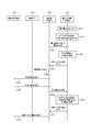
- Step S201 When the consumer selects the driving end button 206 displayed on the display unit 135, the control unit 133 transmits a driving end notification indicating that the driving end button 206 has been selected to the control unit 126 of the facility 120 together with the vehicle information.
- the control unit 126 transmits the driving end notification and the vehicle information acquired from the control unit 133 to the control unit 114 (step S202).
- the control unit 114 updates the predicted value of the amount of power that can be supplied to the system 115 by the storage battery 132 of the vehicle 130 (step S203). At this time, if the control unit 114 has acquired a driving end notification, the control unit 114 determines that all the remaining amount of the storage battery 132 of the vehicle 130 can be supplied to the system 115, and the entire remaining amount of the storage battery 132 is converted to the system 115. The predicted value is updated so as to be included in the amount of power that can be supplied to the power source.
- the control unit 114 supplies power to the system 115 from the storage battery 132 that is electrically connected to the system 115, for example, when the amount of power demand in the facility 120 exceeds the power generated by the power supply network 110, as necessary. To control.
- the system 115 can supply the power supplied from the storage battery 132 to the facility 120 electrically connected to the system 115.
- the power management system 100 when the consumer does not use the vehicle 130, the storage battery 132 included in the vehicle 130 can be used as a power source. Therefore, according to the power management system 100, when the consumer uses the vehicle 130, the power of the vehicle 130 is not consumed. On the other hand, when the consumer does not use the vehicle 130, the power of the vehicle 130 is consumed. By making it possible, the power supply can be stabilized.
- the operation end button 206 is changed to the operation resumption button 306 in comparison with the screen 200 of FIG.
- the consumer selects the driving resumption button 306 when he / she travels the vehicle 130 again after selecting the driving end button 206 once.
- the operation restart button 306 the display on the display unit 135 is switched from the screen 300 to the screen 200, and a part of the remaining amount of the storage battery 132 is assigned as “for travel”.
- FIG. 7 illustrates a case where the customer selects the operation restart button 306 displayed on the display unit 135 of the vehicle 130 as in the description of FIG.
- Step S301 When the consumer selects the operation restart button 306 displayed on the display unit 135, the control unit 133 transmits an operation restart notification indicating that the operation restart button 306 has been selected to the control unit 126 of the facility 120 together with the vehicle information.
- the control unit 126 transmits the operation resumption notification and the vehicle information acquired from the control unit 133 to the control unit 114 (step S302).
- the control unit 114 updates the predicted value of the amount of power that can be supplied to the system 115 by the storage battery 132 of the vehicle 130 (step S303). At this time, the control unit 114 determines that it is impossible to supply power to the system 115 from the storage battery 132 of the vehicle 130 according to the operation resumption notification, and the remaining power of the storage battery 132 of the vehicle 130 can be supplied to the system 115. To update the predicted value.
- the customer can drive, for example, when it becomes necessary to drive. Therefore, according to the power management system 100, convenience for consumers is improved.
- the operation end notification and the operation resumption notification are transmitted from the control unit 133 when the consumer selects the operation end button 206 and the operation resumption button 306, respectively. May be transmitted based on other operations.
- the operation end notification and the operation resumption notification may be transmitted based on, for example, an operation on a charging plug for a customer to connect the facility 120 and the vehicle 130.
- the consumer can simultaneously transmit a driving end notification and a driving resumption notification when the charging plug 400 is attached to or detached from the vehicle 130.
- the charging plug 400 includes a connection portion 401, a lever 402, a removal prevention claw 403, and an operation switch 404.
- the consumer connects the charging plug 400 to the vehicle 130 by connecting (inserting) the connecting portion 401 to the connection I / F 131 (inlet) of the vehicle 130 while operating the lever 402.
- the disconnection prevention claw 403 prevents the connection part 401 inserted into the connection I / F 131 from unintentionally disconnecting.
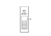
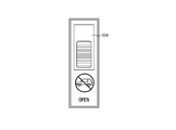
- FIG. 9 and 10 are diagrams showing the operation switch 404 in a top view of the charging plug 400.
- FIG. The operation switch 404 has an anti-slip so as to be easily operated on the upper surface, for example. The consumer operates to the first position and the second position by sliding the operation switch 404.
- the operation switch 404 When the customer operates the vehicle 130 during the same day, the operation switch 404 is operated so as to be in the first position as shown in FIG. 9, for example. Therefore, for example, when the consumer connects the charging plug 400 to the connection I / F 131 and the operation switch 404 is left in the first position, the operation end notification is not transmitted.
- the operation switch 404 When the customer does not drive the vehicle 130 during the same day, the user operates the operation switch 404 so as to be in the second position as shown in FIG. 10, for example. Therefore, for example, when the consumer connects the charging plug 400 to the connection I / F 131, the operation end notification is transmitted by moving the operation switch 404 from the first position to the second position.
- an operation resumption notification is transmitted. Therefore, for example, when it is necessary to drive the vehicle 130, the consumer moves the position of the operation switch 404 from the second position to the first position when removing the charging plug 400 from the connection I / F 131. Thus, a driving resumption notification can be transmitted.
- the consumer can operate the position of the operation switch 404 when the charging plug 400 is detached from the connection I / F 131. . Since the operation end notification and the operation resumption notification are automatically transmitted by the operation of the position of the operation switch 404, the charging plug 400 can improve convenience.
- control unit 114 acquires information on the state of the storage battery 132, and based on the information on the state of the storage battery 132 and the operation input (operation end notification) from the user of the vehicle 130, It is determined that the stored power can be supplied to system 115.
- control is performed so that power is supplied to the system 115 from the storage battery 132 electrically connected to the system 115 as necessary.
- the power management system 100 when the consumer does not use the vehicle 130, the power supply can be stabilized by making the power of the vehicle 130 consuming.
- each component can be rearranged so as not to be logically contradictory, and a plurality of components or the like can be combined into one or divided.
- control unit 114 performs control so that power is supplied to the system 115 from the storage battery 132 electrically connected to the system 115 as necessary.
- the stored power of the storage battery 132 may be supplied to the load 122 in the facility 120.
- the power management system 100 includes the vehicle 130 including the storage battery 132. However, the power management system 100 does not necessarily have the vehicle 130. If the power management system 100 has a movable device including the storage battery 132, for example, the same power management method as that in the above embodiment can be realized.
- the vehicle 130 or a movable device that replaces the vehicle 130 may include a power generation device together with or instead of the storage battery 132.
- the control unit 114 can supply the power generated by the power generation device to the system 115.
- a vehicle including a power generation device for example, a fuel cell vehicle and the like can be given.
- the facility 120 has been described as being a consumer's residence, but the facility 120 is not necessarily a consumer's residence.
- the facility 120 may be a company, for example.
- the user of the vehicle 130 can connect the vehicle 130 to a charging cable provided by the company after work, for example, so that the stored power of the storage battery 132 can be supplied to the system 115.
- Electric power management system 110 Electric power supply network 111 Power station 112 Power supply command center 113 Electric power retail company 114 Electric power supply control part 115 System (electric power system) 120 facilities 121 power transmission / reception unit 122 load 123 power conditioner (PCS) 124, 131 connection interface 125 communication unit 126 facility side control unit 127 display unit 130 vehicle 132 storage battery 133 vehicle side control unit 134 driving operation unit 135 display unit 136 motor 137 ECU 140 Network 150 Power management device 200, 300 Screen 201 Travelable distance 202 Recommended travel distance range 203 Power saving event 204 Power saving event cooperation information 205 Remaining information graph 206 Operation end button 306 Operation restart button 400 Charging plug 401 Connection unit 402 Lever 403 Removal Prevention claw 404 Operation switch
Landscapes
- Engineering & Computer Science (AREA)
- Power Engineering (AREA)
- Transportation (AREA)
- Mechanical Engineering (AREA)
- Life Sciences & Earth Sciences (AREA)
- Sustainable Development (AREA)
- Sustainable Energy (AREA)
- Charge And Discharge Circuits For Batteries Or The Like (AREA)
- Electric Propulsion And Braking For Vehicles (AREA)
- Remote Monitoring And Control Of Power-Distribution Networks (AREA)
- Supply And Distribution Of Alternating Current (AREA)
Abstract
Description
110 電力供給ネットワーク
111 発電所
112 給電指令所
113 電力小売会社
114 電力供給制御部
115 系統(電力系統)
120 施設
121 電力送受電部
122 負荷
123 パワーコンディショナ(PCS)
124、131 接続インタフェース
125 通信部
126 施設側制御部
127 表示部
130 車両
132 蓄電池
133 車両側制御部
134 運転操作部
135 表示部
136 モータ
137 ECU
140 ネットワーク
150 電力管理装置
200、300 画面
201 走行可能距離
202 走行推奨距離範囲
203 節電イベント
204 節電イベント協力情報
205 残量情報グラフ
206 運転終了ボタン
306 運転再開ボタン
400 充電プラグ
401 接続部
402 レバー
403 抜け防止ツメ
404 操作スイッチ
Claims (15)
- 系統から施設の負荷への電力供給を制御する制御部を備える電力管理装置であって、
前記制御部は、車両に搭載された蓄電池が前記系統に電気的に接続された状態において、前記蓄電池の状態に関する情報を取得し、該情報と、前記車両の操作入力とに基づいて、前記蓄電池の蓄電電力を前記系統及び前記負荷の少なくとも一方に供給する、
電力管理装置。 - 前記制御部は、前記情報に基づき、前記系統及び前記蓄電池から前記施設の前記負荷に供給可能な電力の予測値を算出する、請求項1に記載の電力管理装置。
- 前記制御部は、前記操作入力として、前記車両を運転しない旨の通知を取得した場合、前記蓄電池の蓄電電力を前記系統及び前記負荷の少なくとも一方に供給する、請求項1又は請求項2に記載の電力管理装置。
- 前記制御部は、前記操作入力として、前記車両の運転を再開する旨の通知を取得した場合、前記供給可能な電力の予測値を更新する、請求項2に記載の電力管理装置。
- 前記蓄電池の状態に関する情報は、前記蓄電池の蓄電電力に関する情報を含む、請求項1乃至請求項4のいずれか一項に記載の電力管理装置。
- 車両に搭載され、系統に電気的に接続可能な蓄電池と、
前記系統から施設の負荷への電力供給を制御する制御部と、を備え、
前記制御部は、前記蓄電池が前記系統に電気的に接続された状態において、前記蓄電池の状態に関する情報を取得し、該情報と、前記車両の操作入力とに基づいて、前記蓄電池の蓄電電力を前記系統及び前記負荷の少なくとも一方に供給する、
電力管理システム。 - 前記制御部は、前記情報に基づき、前記系統及び前記蓄電池から前記施設の前記負荷に供給可能な電力の予測値を算出する、請求項6に記載の電力管理システム。
- 前記制御部は、前記操作入力として、前記車両を運転しない旨の通知を取得した場合、前記蓄電池の蓄電電力を前記系統及び前記負荷の少なくとも一方に供給する、請求項6又は請求項7に記載の電力管理システム。
- 前記制御部は、前記操作入力として、前記車両の運転を再開する旨の通知を取得した場合、前記供給可能な電力の予測値を更新する、請求項7に記載の電力管理システム。
- 前記蓄電池の状態に関する情報は、前記蓄電池の蓄電電力に関する情報を含む、請求項6乃至請求項9のいずれか一項に記載の電力管理システム。
- 系統から施設の負荷への電力供給を制御する制御部を備える電力管理装置による電力管理方法であって、
車両に搭載された蓄電池が前記系統に電気的に接続された状態において、
前記制御部が、前記蓄電池の状態に関する情報を取得するステップと、
前記情報と、前記車両の操作入力とに基づいて、前記蓄電池の蓄電電力を前記系統及び前記負荷の少なくとも一方に供給するステップと
を含む、電力管理方法。 - 前記情報に基づき、前記系統及び前記蓄電池から前記施設の前記負荷に供給可能な電力の予測値を算出するステップをさらに含む、請求項11に記載の電力管理方法。
- 前記操作入力として、前記車両を運転しない旨の通知を取得した場合、前記蓄電池の蓄電電力を前記系統及び前記負荷の少なくとも一方に供給するステップをさらに含む、請求項11又は請求項12に記載の電力管理方法。
- 前記操作入力として、前記車両の運転を再開する旨の通知を取得した場合、前記供給可能な電力の予測値を更新するステップをさらに含む、請求項12に記載の電力管理方法。
- 前記蓄電池の状態に関する情報は、前記蓄電池の蓄電電力に関する情報を含む、請求項11乃至請求項14のいずれか一項に記載の電力管理方法。
Priority Applications (4)
| Application Number | Priority Date | Filing Date | Title |
|---|---|---|---|
| EP17775275.5A EP3439130A4 (en) | 2016-03-29 | 2017-03-29 | SERVICE MANAGEMENT SYSTEM, SERVICE MANAGEMENT SYSTEM AND SERVICE MANAGEMENT PROCESS |
| US16/089,355 US11230204B2 (en) | 2016-03-29 | 2017-03-29 | Power management apparatus, power management system, and power management method |
| CN201780021392.1A CN108886255B (zh) | 2016-03-29 | 2017-03-29 | 电力管理装置、电力管理系统以及电力管理方法 |
| JP2018509365A JP6639646B2 (ja) | 2016-03-29 | 2017-03-29 | 電力管理装置、電力管理システム及び電力管理方法 |
Applications Claiming Priority (2)
| Application Number | Priority Date | Filing Date | Title |
|---|---|---|---|
| JP2016066828 | 2016-03-29 | ||
| JP2016-066828 | 2016-03-29 |
Publications (1)
| Publication Number | Publication Date |
|---|---|
| WO2017170741A1 true WO2017170741A1 (ja) | 2017-10-05 |
Family
ID=59964623
Family Applications (1)
| Application Number | Title | Priority Date | Filing Date |
|---|---|---|---|
| PCT/JP2017/013015 Ceased WO2017170741A1 (ja) | 2016-03-29 | 2017-03-29 | 電力管理装置、電力管理システム及び電力管理方法 |
Country Status (5)
| Country | Link |
|---|---|
| US (1) | US11230204B2 (ja) |
| EP (1) | EP3439130A4 (ja) |
| JP (1) | JP6639646B2 (ja) |
| CN (1) | CN108886255B (ja) |
| WO (1) | WO2017170741A1 (ja) |
Cited By (4)
| Publication number | Priority date | Publication date | Assignee | Title |
|---|---|---|---|---|
| KR20190080750A (ko) * | 2017-12-28 | 2019-07-08 | 도요타 지도샤(주) | 자동차 |
| WO2020148850A1 (ja) * | 2019-01-17 | 2020-07-23 | 本田技研工業株式会社 | 容量制御装置及びプログラム |
| WO2023170931A1 (ja) * | 2022-03-11 | 2023-09-14 | 本田技研工業株式会社 | バッテリ管理システム、及びバッテリ管理方法 |
| JPWO2023170932A1 (ja) * | 2022-03-11 | 2023-09-14 |
Families Citing this family (8)
| Publication number | Priority date | Publication date | Assignee | Title |
|---|---|---|---|---|
| JP2019131112A (ja) * | 2018-02-01 | 2019-08-08 | 本田技研工業株式会社 | 車両制御システム、車両制御方法、およびプログラム |
| JP6913114B2 (ja) * | 2019-01-17 | 2021-08-04 | 本田技研工業株式会社 | 制御装置及びプログラム |
| JP6874026B2 (ja) * | 2019-01-17 | 2021-05-19 | 本田技研工業株式会社 | 送受電管理装置及びプログラム |
| JP7108552B2 (ja) * | 2019-01-25 | 2022-07-28 | 本田技研工業株式会社 | 管理装置、管理方法、及びプログラム |
| JP2021149331A (ja) * | 2020-03-17 | 2021-09-27 | トヨタ自動車株式会社 | 電動車両の電力取引システム及び充放電装置 |
| JP7474623B2 (ja) * | 2020-03-27 | 2024-04-25 | 本田技研工業株式会社 | 電力算出装置 |
| JP7831390B2 (ja) * | 2023-05-10 | 2026-03-17 | トヨタ自動車株式会社 | 電力需給システム |
| EP4683153A1 (en) * | 2024-07-19 | 2026-01-21 | Hager-Electro Sas | Method for controlling an electric vehicle charging station for powering a domestic electric grid and power supply system for powering such a domestic electric grid |
Citations (4)
| Publication number | Priority date | Publication date | Assignee | Title |
|---|---|---|---|---|
| JPH10271694A (ja) * | 1997-03-24 | 1998-10-09 | Nissan Motor Co Ltd | 2次電池の充放電システム |
| JP2012023797A (ja) * | 2010-07-12 | 2012-02-02 | Tokyo Metropolitan Univ | 電力分配装置、電力分配プログラム、電力分配システム、及び電力分配方法 |
| WO2012017937A1 (ja) * | 2010-08-05 | 2012-02-09 | 三菱自動車工業株式会社 | 電力需給平準化システム |
| US20120157083A1 (en) * | 2010-12-16 | 2012-06-21 | General Motors Llc | System and method for providing discharge authorization to a battery-powered vehicle via a telematics system |
Family Cites Families (28)
| Publication number | Priority date | Publication date | Assignee | Title |
|---|---|---|---|---|
| PL206457B1 (pl) | 2002-01-24 | 2010-08-31 | Aloys Wobben | Sposób i układ zasilania energią elektryczną pojazdu silnikowego |
| JP4232789B2 (ja) * | 2006-04-24 | 2009-03-04 | トヨタ自動車株式会社 | 内燃機関の停止制御装置および停止制御方法 |
| JP4265629B2 (ja) * | 2006-08-01 | 2009-05-20 | トヨタ自動車株式会社 | 二次電池の充放電制御装置およびそれを搭載したハイブリッド車両 |
| JP2008054439A (ja) | 2006-08-25 | 2008-03-06 | Toyota Motor Corp | 電力システム |
| KR20100111658A (ko) | 2007-07-26 | 2010-10-15 | 그린박스 테크놀러지 인크. | 그리드와 차량 사이의 전력 전송 시스템 및 그 방법 |
| JP5179582B2 (ja) * | 2008-06-27 | 2013-04-10 | シャープ株式会社 | 電力を電力需要施設に分配する電力制御システム |
| JP5291422B2 (ja) * | 2008-09-29 | 2013-09-18 | 大阪瓦斯株式会社 | 電力需給システム |
| JP2011083058A (ja) * | 2009-10-02 | 2011-04-21 | Panasonic Electric Works Co Ltd | 電力供給システムの蓄電池電力供給源監視装置 |
| US8359132B2 (en) * | 2010-06-16 | 2013-01-22 | Toyota Motor Engineering & Manufacturing North America, Inc. | System and method for optimizing use of a battery |
| US9696176B2 (en) * | 2011-01-06 | 2017-07-04 | Ford Global Technologies, Llc | Information display system and method |
| JP2013046557A (ja) | 2011-08-26 | 2013-03-04 | Sharp Corp | 宅内放電制御装置および宅内放電制御方法 |
| JP5873986B2 (ja) * | 2011-09-20 | 2016-03-01 | パナソニックIpマネジメント株式会社 | 充電システム、サーバ装置、及び、サーバ装置のプログラム |
| JP5899450B2 (ja) * | 2011-11-08 | 2016-04-06 | パナソニックIpマネジメント株式会社 | 電力管理装置 |
| JP5967516B2 (ja) * | 2011-11-22 | 2016-08-10 | パナソニックIpマネジメント株式会社 | 電力管理装置、電力管理プログラム、及び、電力分配システム |
| JP5919525B2 (ja) | 2011-11-22 | 2016-05-18 | パナソニックIpマネジメント株式会社 | 車両管理システム |
| WO2014033915A1 (ja) * | 2012-08-31 | 2014-03-06 | トヨタ自動車株式会社 | 車両および車両の制御方法 |
| CN103078360B (zh) * | 2012-10-29 | 2016-04-20 | 中国电力科学研究院 | 规模化电动汽车集群供电系统 |
| JP2015015800A (ja) * | 2013-07-03 | 2015-01-22 | パナソニックIpマネジメント株式会社 | 制御装置、電力管理システム |
| CN103595107B (zh) * | 2013-12-02 | 2015-11-11 | 国家电网公司 | 电动汽车充放电控制系统及方法 |
| US20150255984A1 (en) * | 2014-03-05 | 2015-09-10 | Nissan North America, Inc. | Vehicle-to-grid system control based on state of health |
| WO2015146200A1 (ja) * | 2014-03-27 | 2015-10-01 | 京セラ株式会社 | 電力管理システム、電力管理方法、及び制御装置 |
| WO2015145784A1 (en) * | 2014-03-27 | 2015-10-01 | Nec Corporation | Energy management method and system for energy supply system |
| US10026998B2 (en) * | 2014-05-15 | 2018-07-17 | Ford Global Technologies, Llc | Electric vehicle operation to manage battery capacity |
| JP2015220862A (ja) * | 2014-05-16 | 2015-12-07 | トヨタ自動車株式会社 | 電力管理システム |
| CN104319853B (zh) * | 2014-11-14 | 2016-08-17 | 国家电网公司 | 电动汽车入网的方法、装置及系统 |
| US9527400B2 (en) * | 2015-01-30 | 2016-12-27 | Ford Global Technologies, Llc | Smart energy management to improve electrified vehicle battery life |
| CN104753164B (zh) * | 2015-04-16 | 2018-12-18 | 国网河南省电力公司开封供电公司 | 一种v2g充电站 |
| CN104701931B (zh) * | 2015-04-18 | 2017-02-22 | 国家电网公司 | 一种规模化电动汽车的可放电容量评估方法 |
-
2017
- 2017-03-29 EP EP17775275.5A patent/EP3439130A4/en active Pending
- 2017-03-29 JP JP2018509365A patent/JP6639646B2/ja active Active
- 2017-03-29 CN CN201780021392.1A patent/CN108886255B/zh active Active
- 2017-03-29 WO PCT/JP2017/013015 patent/WO2017170741A1/ja not_active Ceased
- 2017-03-29 US US16/089,355 patent/US11230204B2/en active Active
Patent Citations (4)
| Publication number | Priority date | Publication date | Assignee | Title |
|---|---|---|---|---|
| JPH10271694A (ja) * | 1997-03-24 | 1998-10-09 | Nissan Motor Co Ltd | 2次電池の充放電システム |
| JP2012023797A (ja) * | 2010-07-12 | 2012-02-02 | Tokyo Metropolitan Univ | 電力分配装置、電力分配プログラム、電力分配システム、及び電力分配方法 |
| WO2012017937A1 (ja) * | 2010-08-05 | 2012-02-09 | 三菱自動車工業株式会社 | 電力需給平準化システム |
| US20120157083A1 (en) * | 2010-12-16 | 2012-06-21 | General Motors Llc | System and method for providing discharge authorization to a battery-powered vehicle via a telematics system |
Non-Patent Citations (1)
| Title |
|---|
| See also references of EP3439130A4 * |
Cited By (21)
| Publication number | Priority date | Publication date | Assignee | Title |
|---|---|---|---|---|
| US11180031B2 (en) | 2017-12-28 | 2021-11-23 | Toyota Jidosha Kabushiki Kaisha | Vehicle |
| CN109986996A (zh) * | 2017-12-28 | 2019-07-09 | 丰田自动车株式会社 | 汽车 |
| JP2019122066A (ja) * | 2017-12-28 | 2019-07-22 | トヨタ自動車株式会社 | 自動車 |
| EP3505390B1 (en) * | 2017-12-28 | 2023-07-26 | Toyota Jidosha Kabushiki Kaisha | Vehicle to grid management system |
| KR102275924B1 (ko) * | 2017-12-28 | 2021-07-12 | 도요타 지도샤(주) | 자동차 |
| KR20190080750A (ko) * | 2017-12-28 | 2019-07-08 | 도요타 지도샤(주) | 자동차 |
| JP7013864B2 (ja) | 2017-12-28 | 2022-02-01 | トヨタ自動車株式会社 | 自動車 |
| JP2022110032A (ja) * | 2019-01-17 | 2022-07-28 | 本田技研工業株式会社 | 容量制御装置及びプログラム |
| US11807122B2 (en) | 2019-01-17 | 2023-11-07 | Honda Motor Co., Ltd. | Capacity control device and computer-readable medium |
| JP7069352B2 (ja) | 2019-01-17 | 2022-05-17 | 本田技研工業株式会社 | 容量制御装置及びプログラム |
| CN113228453A (zh) * | 2019-01-17 | 2021-08-06 | 本田技研工业株式会社 | 容量控制装置和程序 |
| WO2020148850A1 (ja) * | 2019-01-17 | 2020-07-23 | 本田技研工業株式会社 | 容量制御装置及びプログラム |
| CN113228453B (zh) * | 2019-01-17 | 2024-07-02 | 本田技研工业株式会社 | 容量控制装置和计算机可读存储介质 |
| JPWO2020148850A1 (ja) * | 2019-01-17 | 2021-11-04 | 本田技研工業株式会社 | 容量制御装置及びプログラム |
| JP7357105B2 (ja) | 2019-01-17 | 2023-10-05 | 本田技研工業株式会社 | 容量制御装置及びプログラム |
| JPWO2023170931A1 (ja) * | 2022-03-11 | 2023-09-14 | ||
| WO2023170932A1 (ja) * | 2022-03-11 | 2023-09-14 | 本田技研工業株式会社 | バッテリ管理システム、及びバッテリ管理方法 |
| JPWO2023170932A1 (ja) * | 2022-03-11 | 2023-09-14 | ||
| WO2023170931A1 (ja) * | 2022-03-11 | 2023-09-14 | 本田技研工業株式会社 | バッテリ管理システム、及びバッテリ管理方法 |
| JP7628656B2 (ja) | 2022-03-11 | 2025-02-10 | 本田技研工業株式会社 | バッテリ管理システム、及びバッテリ管理方法 |
| JP7671916B2 (ja) | 2022-03-11 | 2025-05-02 | 本田技研工業株式会社 | バッテリ管理システム、及びバッテリ管理方法 |
Also Published As
| Publication number | Publication date |
|---|---|
| JPWO2017170741A1 (ja) | 2019-01-31 |
| US11230204B2 (en) | 2022-01-25 |
| EP3439130A1 (en) | 2019-02-06 |
| CN108886255B (zh) | 2021-11-23 |
| JP6639646B2 (ja) | 2020-02-05 |
| US20190111805A1 (en) | 2019-04-18 |
| EP3439130A4 (en) | 2019-10-16 |
| CN108886255A (zh) | 2018-11-23 |
Similar Documents
| Publication | Publication Date | Title |
|---|---|---|
| JP6639646B2 (ja) | 電力管理装置、電力管理システム及び電力管理方法 | |
| CN105277890B (zh) | 电池容量退化指示 | |
| US8854006B2 (en) | Charge control device | |
| JP5666593B2 (ja) | 電力需給平準化システムのバッテリ情報出力装置 | |
| JP5355641B2 (ja) | 電力供給システム | |
| JP5900249B2 (ja) | 電力供給システム | |
| RU2639142C2 (ru) | Устройство управления электрическим аппаратом и система управления энергопотреблением | |
| EP3530518A1 (en) | Vehicle and method of notifying charging information of vehicle | |
| US10421366B2 (en) | Energy management of an electrified vehicle | |
| CN105263739A (zh) | 电池和充电装置管理系统、方法以及充电装置 | |
| JP5673474B2 (ja) | 電力切替装置 | |
| JP2014166846A (ja) | プラグインハイブリッドおよび電気車両の電気管理方法 | |
| WO2014208561A1 (ja) | 充電状態管理方法、充電状態管理装置およびプログラム | |
| US20180022227A1 (en) | Battery charging systems and associated methods of use | |
| CN114665464A (zh) | 服务器、电力管理方法 | |
| CN118139760A (zh) | 用于对能电驱动的车辆的牵引电池进行充电的方法、车辆和充电装置 | |
| CN114665461A (zh) | 服务器、电力管理方法 | |
| JP7809985B2 (ja) | 充放電制御装置、プログラム及び充放電制御方法 | |
| JP2015228716A (ja) | 電気自動車のバッテリー管理装置 | |
| JP7818028B2 (ja) | 電力制御システムおよび電力制御方法 | |
| JP7639842B2 (ja) | 出力装置及び出力システム | |
| US20230020971A1 (en) | Method for controlling power transfer from a grid to a vehicle | |
| US20250332958A1 (en) | Management system, vehicle, and method of managing power storage device | |
| US20250135937A1 (en) | Vehicle and system | |
| WO2025163728A1 (ja) | 電動車両の給電制御方法、及び電動車両の給電制御システム |
Legal Events
| Date | Code | Title | Description |
|---|---|---|---|
| WWE | Wipo information: entry into national phase |
Ref document number: 2018509365 Country of ref document: JP |
|
| NENP | Non-entry into the national phase |
Ref country code: DE |
|
| WWE | Wipo information: entry into national phase |
Ref document number: 2017775275 Country of ref document: EP |
|
| ENP | Entry into the national phase |
Ref document number: 2017775275 Country of ref document: EP Effective date: 20181029 |
|
| 121 | Ep: the epo has been informed by wipo that ep was designated in this application |
Ref document number: 17775275 Country of ref document: EP Kind code of ref document: A1 |