WO2017170806A1 - 作業機械の旋回フレーム、およびこれを備えた作業機械 - Google Patents
作業機械の旋回フレーム、およびこれを備えた作業機械 Download PDFInfo
- Publication number
- WO2017170806A1 WO2017170806A1 PCT/JP2017/013128 JP2017013128W WO2017170806A1 WO 2017170806 A1 WO2017170806 A1 WO 2017170806A1 JP 2017013128 W JP2017013128 W JP 2017013128W WO 2017170806 A1 WO2017170806 A1 WO 2017170806A1
- Authority
- WO
- WIPO (PCT)
- Prior art keywords
- pair
- frame
- swivel
- reinforcing members
- bearing
- Prior art date
- Legal status (The legal status is an assumption and is not a legal conclusion. Google has not performed a legal analysis and makes no representation as to the accuracy of the status listed.)
- Ceased
Links
Images


Classifications
-
- B—PERFORMING OPERATIONS; TRANSPORTING
- B66—HOISTING; LIFTING; HAULING
- B66C—CRANES; LOAD-ENGAGING ELEMENTS OR DEVICES FOR CRANES, CAPSTANS, WINCHES, OR TACKLES
- B66C23/00—Cranes comprising essentially a beam, boom, or triangular structure acting as a cantilever and mounted for translatory of swinging movements in vertical or horizontal planes or a combination of such movements, e.g. jib-cranes, derricks, tower cranes
- B66C23/18—Cranes comprising essentially a beam, boom, or triangular structure acting as a cantilever and mounted for translatory of swinging movements in vertical or horizontal planes or a combination of such movements, e.g. jib-cranes, derricks, tower cranes specially adapted for use in particular purposes
- B66C23/36—Cranes comprising essentially a beam, boom, or triangular structure acting as a cantilever and mounted for translatory of swinging movements in vertical or horizontal planes or a combination of such movements, e.g. jib-cranes, derricks, tower cranes specially adapted for use in particular purposes mounted on road or rail vehicles; Manually-movable jib-cranes for use in workshops; Floating cranes
-
- B—PERFORMING OPERATIONS; TRANSPORTING
- B66—HOISTING; LIFTING; HAULING
- B66C—CRANES; LOAD-ENGAGING ELEMENTS OR DEVICES FOR CRANES, CAPSTANS, WINCHES, OR TACKLES
- B66C23/00—Cranes comprising essentially a beam, boom, or triangular structure acting as a cantilever and mounted for translatory of swinging movements in vertical or horizontal planes or a combination of such movements, e.g. jib-cranes, derricks, tower cranes
- B66C23/62—Constructional features or details
Definitions
- the present invention relates to a swing frame supported by a lower traveling body of a work machine via a swing bearing so as to be swingable, and a work machine including the same.
- an upper swing body is provided so as to be swingable on an upper portion of a lower traveling body via a swing bearing.
- the upper swing body includes a swing frame that is pivotably attached to a swing bearing, a boom that lifts a suspended load, and the like, and a mast.
- the work machine includes, for example, an upper spreader provided at the tip of the mast and a lower spreader provided on the swivel frame.
- the boom is raised and lowered by raising and lowering the mast by the raising and lowering rope hung between the upper spreader and the lower spreader.
- the front part of the revolving frame is provided with a boom foot part that supports the base end part of the boom
- the front part of the upper surface part of the revolving frame is provided with a mast foot part that supports the base end part of the mast.
- the lower spreader described above is provided on the rear portion of the upper surface of the revolving frame.
- the boom foot part, the mast foot part, and the lower spreader are subject to the boom's own weight or a suspension load caused by a suspended load.
- the load generated by the work machine taking various postures and the load generated by the suspended load work act on the swing frame and cause the swing frame to be deformed. This deformation affects the deflection of the tip of the boom and the tip of the jib attached to the tip of the boom. As a result, there is a problem that the suspension capacity of the work machine is limited.
- An object of the present invention is to provide a swing frame for a work machine capable of improving the suspension capacity of the work machine while suppressing an increase in the weight of the vehicle, and a work machine equipped with the same.
- the swivel frame is supported by a lower traveling body of the work machine via a swivel bearing so as to be able to swivel around a swivel center extending in the vertical direction, and supports the mast and the boom.
- the swivel frame includes a bottom plate, a pair of left and right side plates, a rear end member, a pair of boom foot portions, a pair of mast foot portions, a mast connecting portion, a pair of left and right first reinforcing members, and a pair of left and right pairs.
- the bottom plate has a bottom plate upper surface portion and a bottom plate lower surface portion to which the slewing bearing is fixed.
- the pair of left and right side plates have a side plate upper surface portion, a side plate front end portion, and a side plate rear end portion, respectively, extend along the front-rear direction of the swivel frame, and sandwich the swivel center in the left-right direction of the swivel frame. It arrange
- the rear end member connects the side plate rear end portions of the pair of left and right side plates along the left-right direction.
- a pair of boom foot portions are provided at the front end portions of the left and right side plates, respectively, and support the base end portion of the boom.
- the pair of mast foot portions are respectively provided in front portions of the side plate upper surface portions of the pair of left and right side plates, and support a base end portion of the mast.
- a mast connection part is provided in the said rear end member, and is connected with the said mast via a connection member.
- the pair of left and right first reinforcing members are disposed so as to extend from the boom foot portion toward the front side portion of the swing bearing when the swing frame is viewed along the left-right direction.
- a lower end connected to the front portion of the slewing bearing is provided.
- the pair of left and right second reinforcing members are disposed so as to extend from the boom foot portion toward the mast foot portion when the revolving frame is viewed along the left-right direction.
- the pair of left and right third reinforcing members are disposed so as to extend from the mast foot portion toward the rear side portion of the swivel bearing when the swivel frame is viewed along the left-right direction.
- a pair of left and right fourth reinforcing members, when the swivel frame is viewed along the left-right direction, are formed from an intermediate region located above the rear portion of the swivel bearing in the upper part of the side plate.
- the lower end portion is provided so as to extend toward the front side portion, and is connected to the front side portion of the slewing bearing.
- the pair of left and right fifth reinforcing members are disposed so as to extend from the intermediate region toward the rear side portion of the swivel bearing when the swivel frame is viewed along the left-right direction.
- a lower end portion connected to the rear portion of the slewing bearing is provided.
- the first reinforcing member is provided from the boom foot portion to the front side portion of the swing bearing, and the second reinforcing member is provided from the boom foot portion to the mast foot portion.
- the third reinforcing member is provided from the mast foot portion to the rear side portion of the swivel bearing.
- a fourth reinforcing member is provided from the intermediate region located above the rear portion of the slewing bearing in the upper portion of the side plate to the front portion of the slewing bearing, and the fifth reinforcing member is provided from the intermediate region to the rear portion of the slewing bearing.
- a member is provided.
- a compression load acts between the boom foot and the front part of the swing bearing due to the boom's own weight or suspended load, but the first reinforcing member improves the rigidity of the part between them, so The deformation in the portion is suppressed.
- a compressive load acts between the boom foot portion and the mast foot portion, but the rigidity of the portion between them is improved by the second reinforcing member. Is suppressed.
- a tensile load acts between the mast foot portion and the rear portion of the slewing bearing, but the third reinforcing member improves the rigidity of the portion between them, so Deformation in the portion is suppressed.
- a compressive load acts between the intermediate region and the front portion of the slewing bearing, but the rigidity of the portion between them is improved by the fourth reinforcing member. Deformation is suppressed.
- a tensile load acts between the intermediate region and the rear portion of the slewing bearing, but the fifth reinforcing member increases the rigidity of the portion between them, so the portion between these The deformation in is suppressed.
- the suspension capacity of the work machine can be improved.
- the rigidity of the portion where the load acts on the five reinforcing members is efficiently improved, an increase in weight due to the addition of the reinforcing members can be minimized. Therefore, the suspension capacity of the work machine can be improved while suppressing an increase in the weight of the vehicle.
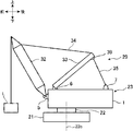
- FIG. 1 is a side view of a crane 20 according to the present embodiment.
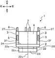
- FIG. 2 is a front view of the revolving frame 1 according to the present embodiment as viewed from the front. In each figure, the front, rear, left, and right directions of the revolving frame 1 are indicated by arrows.
- the front / rear, left / right and up / down directions of the revolving frame 1 coincide with the front / rear, left / right and up / down directions of the crane 20.
- the crane 20 performs an operation of lifting the suspended load L (loading operation) by a boom 32 described later.
- the crane 20 includes a lower traveling body 21, a turning bearing 22, and an upper turning body 23.
- the lower traveling body 21 is a part that causes the crane 20 to travel.
- the lower traveling body 21 is, for example, a crawler type and may be a wheel type.
- the upper swing body 23 is provided on the upper portion of the lower traveling body 21 via the swing bearing 22 so as to be swingable.
- the upper revolving structure 23 includes a revolving frame 1, a boom 32, and a mast 33.
- the boom 32 side of the revolving frame 1 is the front side
- the side of the revolving frame 1 opposite to the boom 32 is the rear side.
- the turning frame 1 is supported by the lower traveling body 11 of the crane 20 via a turning bearing 22 so that the turning frame 1 can turn around a turning center 22c extending in the vertical direction.
- the revolving frame 1 supports the boom 32 and the mast 33 so as to be raised and lowered.
- the swing bearing 22 includes an outer race 22o fixed to the swing frame 1 and an inner race 22i fixed to the lower traveling body 21 (FIG. 2).
- the outer race 22o may be fixed to the lower traveling body 21, and the inner race 22i may be fixed to the turning frame 1.
- the swivel frame 1 is fixed to the upper surface of an annular non-rotating seating surface plate 22a (FIG. 2) attached to the upper surface of the swivel bearing 22 with a plurality of bolts.
- a left frame and a right frame are provided on the left and right sides of the turning frame 1.
- a cab is provided on the right frame.
- a counterweight is provided on the rear side of the turning frame 1 so as to be disassembled. The counterweight is a weight for balancing the suspended load L of the crane 20.
- segmented back and forth on the boundary of the rear part of the turning bearing 22, for example may be sufficient as the turning frame 1.
- the boom 32 has a lattice structure, for example, and is a hoisting member for lifting the suspended load L and the like.
- the boom 32 is attached to the revolving frame 1 at the front end of the revolving frame 1 (side plate front end 3F described later) so as to be raised and lowered.
- the mast 33 is provided at a position on the rear side of the boom 32.
- the tip portion of the mast 33 and the tip portion of the boom 32 are connected to each other via a guy line 34.
- the upper spreader 39 provided at the tip of the mast 33 and the lower spreader 7 (mast connecting part) provided at the rear part of the revolving frame 1 are connected to each other via a boom hoisting rope 35 (connecting member). ing.
- a winch (not shown) provided on the revolving frame 1 winds and unwinds the boom hoisting rope 35, and as a result, the mast 33 rises and lowers, so that the boom 32 rises and falls.
- the base end portion of the boom 32 is attached to the front surface portion (side plate front end portion 3F described later) of the revolving frame 1, and the boom foot portion 5 that supports the base end portion of the boom 32 is provided.
- a base end portion of the mast 33 is attached to the front side portion of the upper surface (side plate upper surface portion 3T described later) of the revolving frame 1, and a mast foot portion 6 that supports the base end portion of the mast 33 is provided.
- the lower spreader 7 described above is provided on the rear portion (the rear end member 4 described later) of the upper surface of the revolving frame 1.
- the swing frame 1 has a bottom plate 2 disposed horizontally above the swing bearing 22.
- the bottom plate 2 is attached to the upper surface of a seating surface plate 22 a attached to the upper surface of the slewing bearing 22.
- a portion of the bottom plate 2 to which the seat surface plate 22a is fixed is defined as a bearing mounting portion.
- the bottom plate 2 has a bottom plate upper surface portion 2A and a bottom plate lower surface portion 2B to which the swivel bearing 22 is fixed via a seating surface plate 22a (FIG. 2).
- the rear end portion of the bottom plate 2 may be disposed in the vicinity of the rear end portion of the slewing bearing 22 in FIG. 3, and is disposed so as to extend rearward to the vicinity of the rear end portion of the seventh reinforcing member 17 described later. May be. That is, the bottom plate 2 may be disposed at least above the swivel bearing 22.
- the revolving frame 1 has a pair of left and right side plates 3.
- the pair of side plates 3 are provided upright on the bottom plate upper surface portion 2A of the bottom plate 2 so as to face each other across the turning center 22c with a predetermined interval in the left-right direction of the turning frame 1.
- the pair of side plates 3 are arranged so as to extend along the front-rear direction of the revolving frame 1.
- Each of the pair of side plates 3 has a side plate upper surface portion 3T (FIG. 2), a side plate front end portion 3F (FIG. 2), and a side plate rear end portion 3B (see FIG. 4A).
- the lower end portion of the side plate 3 is welded to the bottom plate upper surface portion 2 ⁇ / b> A of the bottom plate 2.
- the revolving frame 1 has a front plate (not shown) and a rear end member 4 (see FIGS. 2 and 9).
- the front plate is provided to stand on the bottom plate upper surface portion 2A of the bottom plate 2 at the front side portion of the revolving frame 1 in the front-rear direction, and the front plate and the rear end member 4 are disposed so as to face in the front-rear direction.
- the rear end member 4 is provided on the bottom plate upper surface portion 2A of the bottom plate 2 on the rear side in the front-rear direction of the crane 20, and connects the rear ends (side plate rear end portions 3B) of the pair of side plates 3 along the left-right direction. Note that the front plate is not shown in FIG.
- a pair of boom foot portions 5 are respectively provided on the front surfaces (side plate front end portions 3F) of the pair of side plates 3, and a pair of mast foot portions 6 are provided on the upper surfaces (side plate upper surface portions 3T) of the pair of side plates 3, respectively.
- a pair of lower spreaders 7 is provided on the upper surface of the rear end member 4.
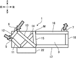
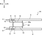
- FIG. 3 is a cross-sectional view of the revolving frame 1 according to the present embodiment as viewed from the left side, and is a cross-sectional view along the front-rear direction and the up-down direction through the central portion of the revolving frame 1 in the horizontal direction.
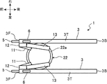
- 4A and 4B are top views of the revolving frame 1 according to the present embodiment. 3 to 4B, some members of the turning frame 1 are omitted. In particular, in FIG. 3 to FIG. 4B, the illustration of the bottom plate 2 is omitted.
- the boom foot 5, the mast foot 6, and the lower spreader 7 are subjected to the weight of the boom 32 and the suspension load due to the suspension load L. These loads act downward and rearward on the boom foot 5, act downward and forward on the mast foot 6, and act upward on the lower spreader 7. These loads are transmitted from the swing frame 1 to the swing bearing 22.
- This deformation affects the deflection of the tip of the boom 32 and the tip of a jib (not shown) attached to the tip of the boom 32.
- the lifting capacity of the crane 20 is limited.
- the revolving frame 1 of the present embodiment includes a pair of left and right first reinforcing members 11, a pair of left and right second reinforcing members 12, and a pair of left and right third reinforcing members. It has a member 13, a pair of left and right fourth reinforcing members 14, and a pair of left and right fifth reinforcing members 15.
- these reinforcing members 11 to 15 are made of metal and have a hollow tubular shape such as a cylinder or a square tube, but may have a plate shape, a column shape, or a prism shape. Further, these reinforcing members 11 to 15 may be provided in the revolving frame 1 from the beginning and may be provided integrally with other members, or may be attached to the revolving frame 1 later.
- the pair of first reinforcing members 11 is configured so that, when the revolving frame 1 is viewed from the side along the left-right direction, the front portion of the upper surface portion of the revolving bearing 22 (revolving) The front portion of the bearing 22 is provided so as to extend linearly.
- the first reinforcing member 11 is disposed so as to connect the boom foot portion 5 and the front portion of the upper surface portion of the swing bearing 22.
- the upper end portion (base end portion) of the first reinforcing member 11 is fixed to the inner surface of the side plate 3, and the lower end portion (tip portion on the swivel bearing 22 side) of the first reinforcing member 11 is fixed to the bottom plate 2. Yes.
- the lower end portion of the first reinforcing member 11 is connected to the front portion of the upper surface portion of the swing bearing 22 via the bottom plate 2 and the seating surface plate 22a.
- the lower end of the first reinforcing member 11 is fixed to the bottom plate 2 at a position spaced from the pair of left and right side plates 3 to the inside in the left-right direction.
- the seat plate 22a attached to the upper surface of the slewing bearing 22 may penetrate the bottom plate 2, and the lower end portion of the first reinforcing member 11 may be fixed to the seat plate 22a.
- a seat surface plate 22a is provided so as to surround the upper surface portion and the side surface portion of the slewing bearing 22, and the lower end portion of the first reinforcing member 11 is interposed via the bottom plate 2 and the seat surface plate 22a.
- the aspect connected to the upper surface part of the slewing bearing 22 may be sufficient.
- the lower end portion of the first reinforcing member 11 is not limited to the configuration connected to the upper surface portion of the slewing bearing 22, and may be connected to the side surface portion of the slewing bearing 22. That is, the swivel bearing 22 may be disposed on the extension line of the first reinforcing member 11.
- FIG. 4A illustration of the bottom plate 2, the front plate, and the rear end member 4 is omitted.
- bolt and welding, can be used for the fixing means of a reinforcement member.
- the pair of second reinforcing members 12 extends linearly from the boom foot 5 to the mast foot 6 when the revolving frame 1 is viewed from the side along the left-right direction. Is provided. As shown in FIG. 4A, the second reinforcing member 12 is disposed so as to connect the boom foot portion 5 and the mast foot portion 6. The side surface of the second reinforcing member 12 is fixed to the inner surface of the side plate 3 from the upper end to the lower end.
- the pair of third reinforcing members 13 are configured so that the rear portion of the upper surface portion of the swivel bearing 22 from the mast foot portion 6 when the swivel frame 1 is viewed from the side along the left-right direction ( It is provided so as to extend linearly over the rear portion of the slewing bearing 22.
- the third reinforcing member 13 is disposed so as to connect the mast foot portion 6 and the rear portion of the upper surface portion of the swivel bearing 22.
- the upper end portion (base end portion) of the third reinforcing member 13 is fixed to the inner surface of the side plate 3, and the lower end portion (tip portion on the swivel bearing 22 side) of the third reinforcing member 13 is fixed to the bottom plate 2. Yes.
- the lower end portion of the third reinforcing member 13 is connected to the rear portion of the upper surface portion of the swivel bearing 22 via the bottom plate 2 and the seat plate 22a.
- the lower end of the third reinforcing member 13 is fixed to the bottom plate 2 at a position spaced from the pair of left and right side plates 3 to the inside in the left-right direction.
- the seat surface board 22a may penetrate the bottom plate 2, and the lower end part of the 3rd reinforcement member 13 may be fixed to the said seat surface board 22a.
- a seat surface plate 22a is provided so as to surround the upper surface portion and the side surface portion of the slewing bearing 22, and the lower end portion of the third reinforcing member 13 is interposed via the bottom plate 2 and the seat surface plate 22a.
- the aspect connected to the upper surface part of the slewing bearing 22 may be sufficient.
- the lower end portion of the third reinforcing member 13 is not limited to the configuration connected to the upper surface portion of the swing bearing 22, and may be connected to the side surface portion of the swing bearing 22. That is, the swivel bearing 22 may be disposed on the extension line of the third reinforcing member 13.
- the pair of fourth reinforcing members 14 are arranged on the front side of the upper surface portion of the slewing bearing 22 from the intermediate region M of the slewing frame 1 when the slewing frame 1 is viewed from the side along the left-right direction. It is provided so as to extend linearly over a portion (a front portion of the slewing bearing 22).
- the intermediate region M of the swing frame 1 is a region located at the upper end portion (near the side plate upper surface portion 3T) of the swing frame 1 and above the rear end portion of the swing bearing 22.
- the fourth reinforcing member 14 is disposed so as to connect the intermediate region M and the front side portion of the upper surface portion of the slewing bearing 22 (the front side portion of the slewing bearing 22).
- the side surface of the fourth reinforcing member 14 is fixed to the inner surface of the side plate 3 from the upper end to the lower end.
- the lower end portion (tip portion on the swing bearing 22 side) of the fourth reinforcing member 14 is fixed to the bottom plate 2.
- the lower end portion of the fourth reinforcing member 14 is connected to the front portion of the upper surface portion of the swivel bearing 22 through the bottom plate 2 and the seating surface plate 22a.
- the seat surface plate 22a may penetrate the bottom plate 2 and the lower end portion of the fourth reinforcing member 14 may be fixed to the seat surface plate 22a.
- FIG. 4B illustration of the bottom plate 2, the front plate, and the rear end member 4 is omitted.
- a seat surface plate 22a is provided so as to surround the upper surface portion and the side surface portion of the slewing bearing 22, and the lower end portion of the fourth reinforcing member 14 is interposed via the bottom plate 2 and the seat surface plate 22a. The aspect connected to the upper surface part of the slewing bearing 22 may be sufficient.
- the lower end portion of the fourth reinforcing member 14 is not limited to the configuration connected to the upper surface portion of the swing bearing 22, and may be connected to the side surface portion of the swing bearing 22. That is, the swivel bearing 22 may be disposed on the extended line of the fourth reinforcing member 14.
- the pair of fifth reinforcing members 15 is configured so that the rear portion of the upper surface portion of the slewing bearing 22 (swirl) when the slewing frame 1 is viewed from the side along the left-right direction.
- the rear part of the bearing 22 is provided so as to extend linearly.
- the fifth reinforcing member 15 is disposed so as to connect the intermediate region M and the rear portion of the upper surface portion of the slewing bearing 22.
- the side surface of the fifth reinforcing member 15 is fixed to the inner surface of the side plate 3 from the upper end to the lower end.
- the lower end portion of the fifth reinforcing member 15 may be fixed to the bottom plate 2 or may be fixed to the front end portion of the seventh reinforcing member 17 described later.
- the lower end portion of the fifth reinforcing member 15 is connected to the upper surface portion of the swing bearing 22 through at least the bottom plate 2 and the seating surface plate 22a.
- a seat surface plate 22a is provided so as to surround the upper surface portion and the side surface portion of the slewing bearing 22, and the lower end portion of the fifth reinforcing member 15 is interposed via the bottom plate 2 and the seat surface plate 22a.
- the aspect connected to the upper surface part of the slewing bearing 22 may be sufficient.
- the lower end portion of the fifth reinforcing member 15 is not limited to the configuration connected to the upper surface portion of the swing bearing 22, and may be connected to the side surface portion of the swing bearing 22. That is, the swivel bearing 22 may be disposed on the extension line of the fifth reinforcing member 15.
- a compressive load acts between the boom foot portion 5 and the front portion of the upper surface portion of the swing bearing 22 due to the weight of the boom 32 and the suspended load L, but the rigidity of the portion between these by the first reinforcing member 11 As a result, deformation in the portion between them is suppressed.
- a compressive load acts between the boom foot part 5 and the mast foot part 6, but the second reinforcing member 12 improves the rigidity of the part between them, so Deformation in the portion is suppressed.
- a tensile load acts between the mast foot portion 6 and the rear portion of the upper surface portion of the slewing bearing 22, but the rigidity of the portion between these is improved by the third reinforcing member 13. Therefore, the deformation
- a compressive load acts between the intermediate region M and the front side portion of the upper surface portion of the slewing bearing 22, but the fourth reinforcing member 14 improves the rigidity of the portion between them, The deformation in the portion between these is suppressed.
- a tensile load acts between the intermediate region M and the rear portion of the upper surface of the slewing bearing 22, but the fifth reinforcing member 15 improves the rigidity of the portion between them, so these Deformation at the intermediate portion is suppressed.
- the suspension capacity of the crane 20 can be improved while suppressing an increase in weight.
- the revolving frame 1 includes a pair of left and right sixth reinforcing members 16, a pair of left and right seventh reinforcing members 17, and a pair of left and right eighth reinforcing members 18, have.
- the reinforcing members 16 to 18 are made of metal and have a hollow tubular shape such as a cylinder or a square tube, but may be a plate shape, a columnar shape, or a prismatic shape. Further, these reinforcing members 16 to 18 may be provided in the revolving frame 1 from the beginning and may be provided integrally with other members, or may be attached to the revolving frame 1 later.
- the pair of sixth reinforcing members 16 are configured such that when the revolving frame 1 is viewed from the side along the left-right direction, the upper portion of the rear surface portion of the revolving frame 1 (rear end member) 4 (upper part of 4). As shown in FIGS. 3 and 4B, the sixth reinforcing member 16 is disposed so as to connect the intermediate region M and the upper portion of the rear surface portion of the revolving frame 1 (upper portion of the rear end member 4). The side surface of the sixth reinforcing member 16 is fixed to the inner surface of the side plate 3 from the front end to the rear end.
- the pair of sixth reinforcing members 16 are disposed so as to extend from the upper end portion of the intermediate region M toward the upper end portion of the rear end member 4 when the revolving frame 22 is viewed along the left-right direction.
- the intermediate region M and the upper end portion of the rear end member 4 are arranged to be connected.
- the pair of seventh reinforcing members 17 is located at a position lower than the sixth reinforcing member 16 when the revolving frame 1 is viewed from the side along the left-right direction. 22 is provided so as to extend in a straight line from a position above the rear portion of 22 to a lower portion of the rear surface portion of the revolving frame 1 (lower portion of the rear end member 4).
- the seventh reinforcing member 17 is located on the back side of the paper surface with respect to the sixth reinforcing member 16, and is a position below the sixth reinforcing member 16 in the side plate 3 and is a slewing bearing.
- the side surface of the seventh reinforcing member 17 is fixed to the inner surface of the side plate 3 from the front end to the rear end. Further, at least the front end portion of the seventh reinforcing member 17 is fixed to the bottom plate 2.
- the lower surface portion of the seventh reinforcing member 17 may be fixed to the bottom plate 2 along the front-rear direction.
- a beam member that connects the pair of side plates 3 may be disposed instead of the bottom plate 2.
- the pair of seventh reinforcing members 17 are positioned below the sixth reinforcing member 16 and above the rear portion of the swing bearing 22 when the swing frame 1 is viewed along the left-right direction. It is disposed so as to extend from the position toward the lower end portion of the rear end member 4, and is located below the sixth reinforcing member 16 in the side plate 3 and above the rear portion of the swivel bearing 22. It is more preferable to arrange so as to connect the lower end portion of the rear end member 4.
- the pair of eighth reinforcing members 18 are configured so that the upper portion of the rear surface portion of the revolving frame 1 (the upper side of the rear end member 4) when the revolving frame 1 is viewed from the side along the left-right direction. Part) to the lower part of the rear surface part of the revolving frame 1 (lower part of the rear end member 4) so as to extend linearly along the vertical direction.
- the eighth reinforcing member 18 extends in the direction perpendicular to the paper surface on the back side of the paper surface from the sixth reinforcing member 16, and the upper portion of the rear surface portion of the swivel frame 1 and the swivel frame 1.
- the side surface of the eighth reinforcing member 18 is fixed to the inner surface of the side plate 3 from the upper end to the lower end. Further, the rear surface portion of the eighth reinforcing member 18 is fixed to the front surface of the rear end member 4.
- the eighth reinforcing member 18 is fixed to the rear end member 4 so as to extend along the vertical direction when the revolving frame 22 is viewed along the left-right direction, and the upper end portion and the lower end portion of the rear end member 4 are fixed. It is more preferable that they are arranged so as to connect each other.
- a tensile load acts along the vertical direction between the upper portion of the rear surface portion of the swivel frame 1 and the lower portion of the rear surface portion of the swivel frame 1. Since the rigidity of the part between these is improved, the deformation
- the load concerning the turning frame 1 is stably transmitted to the front part and the rear part of the turning bearing 22, the deformation of the turning frame 1 can be further suppressed, so that the crane 20 Can be further improved.
- the rigidity of the portion where the load is applied is efficiently improved by the three reinforcing members 16 to 18, an increase in weight due to the addition of the reinforcing members 16 to 18 can be minimized.
- FIG. 5 is a top view of the turning frame 1A according to the first modified embodiment of the present invention.
- illustration of the front plate, the bottom plate, and the rear end member is omitted.
- the side plate 3 is located on the outer side in the left-right direction with respect to the slewing bearing 22, but in the first modified embodiment, as shown in FIG. It is located above the left and right ends.
- the side surfaces of the pair of third reinforcing members 13 are respectively fixed to the inner surfaces of the pair of side plates 3 from the upper end to the lower end.
- the lower end part of the 3rd reinforcement member 13 is being fixed to the baseplate 2 similarly to previous embodiment.
- the pair of first reinforcing members 11 are located on the far side of the paper surface with respect to the pair of second reinforcing members 12 and the pair of third reinforcing members 13.
- the side surface is fixed to the inner surface of the side plate 3 from the upper end to the lower end.
- the lower end part of the 1st reinforcement member 11 is being fixed to the baseplate 2 similarly to previous embodiment.
- the seat surface plate 22a may penetrate the bottom plate 2, and the lower ends of the first reinforcing member 11 and the third reinforcing member 13 may be fixed to the seat surface plate 22a.
- FIG. 6 is a top view of the revolving frame 1B according to the second modified embodiment of the present invention.
- the front plate, the bottom plate, and the rear end member are not shown.
- the side plate 3 is located on the inner side of the left and right ends of the slewing bearing 22.
- the pair of third reinforcing members 13 are respectively disposed on the outer surface sides of the pair of side plates 3, and the side surfaces of the third reinforcing members 13 are fixed to the outer surface portions of the side plates 3 from the upper end to the lower end.
- the lower end portion of the third reinforcing member 13 is fixed to the bottom plate 2 as in the previous embodiment.
- first reinforcing members 11 are respectively disposed on the outer surface sides of the pair of side plates 3, and the side surfaces of the first reinforcing members 11 are fixed to the outer surface portions of the side plates 3 from the upper end to the lower end.
- the lower end portion of the first reinforcing member 11 is fixed to the bottom plate 2 as in the previous embodiment.
- the fourth to eighth reinforcing members 14 to 18 are also fixed to the outer surface of the side plate 3, respectively.
- a rear end member 4 (not shown) (see FIG.
- the reinforcing members 11 to 18 may be provided on the inner surface side and the outer surface side of the side plate 3, respectively.
- the reinforcing members 11 to 18 may be fixed to the inner surface and the outer surface of the side plate 3, respectively.
- a part of each of the reinforcing members 11 to 18 may be spaced apart from the side plate 3.
- the first reinforcing member 11, the third reinforcing member 13, the fourth reinforcing member 14, and the seventh reinforcing member 17 are not limited to the configuration fixed to the bottom plate 2, but are in contact with the bottom plate 2. It may be fixed to the side plate 3. Further, the lower end portion of the fifth reinforcing member 15 may be fixed to the side plate 3 so as to contact the bottom plate 2.
- FIG. 7A is an enlarged side view of the revolving frame 1 according to an embodiment of the present invention.
- FIG. 7B is an enlarged side view of a revolving frame 201 having a conventional structure.
- the revolving frame 1 according to the present embodiment used for the evaluation includes first to fifth reinforcements fixed to the outer surface of the side plate 3 among the first to eighth reinforcement members 11 to 18. Members 11 to 15 are provided.
- FIG. 7A the revolving frame 1 according to the present embodiment used for the evaluation includes first to fifth reinforcements fixed to the outer surface of the side plate 3 among the first to eighth reinforcement members 11 to 18. Members 11 to 15 are provided.
- FIG. 7A is an enlarged side view of the revolving frame 1 according to an embodiment of the present invention.
- FIG. 7B is an enlarged side view of a revolving frame 201 having a conventional structure.
- the revolving frame 1 according to the present embodiment used for the evaluation includes first to fifth reinforcements fixed to the outer surface of the side plate 3 among the
- the frame 201 of the conventional structure used for the evaluation is fixed to the outer surface of the side plate 3 and is provided so as to extend linearly from the mast foot 6 to the center of the swivel bearing 22.
- a member 202 is provided.
- the total weight of the first to fifth reinforcing members 11 to 15 in the present embodiment and the total weight of the reinforcing member 202 of the conventional structure 201 are set to be the same.
- condition (condition 1) that maximizes the boom compression force
- condition (condition 2) that maximizes the tension of the hoisting rope.
- condition (condition 1) at which the boom compressive force is maximized is a condition in which the axial force generated on the boom 32 by the suspended load L is maximized and the load acting on the boom foot portion 5 is maximized.
- condition (condition 2) at which the tension of the hoisting rope is maximized is a condition in which when the suspended load L is suspended, the moment at which the upper revolving structure 23 falls forward is maximized, and the maximum bending occurs in the entire revolving frame.
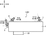
- FIG. 8A is a side view of the swivel frame showing the magnitude and angle of the load acting on the boom foot part 5, the mast foot part 6, and the lower spreader 7 under condition 1.
- 8B is a side view of the swivel frame showing the magnitude and angle of the load acting on the boom foot part 5, the mast foot part 6, and the lower spreader 7 under the condition 2.
- FIG. 9 is a perspective view of the swivel frame showing measurement points for evaluation.
- measurement point A is on the left boom foot 5
- measurement point B is on the right boom foot 5
- measurement point C is on the right lower spreader 7
- measurement point D is on the left lower spreader 7.
- the deformation is 3.8 to 4.5% in the condition 1 and 3.6 to 4.4% in the condition 2, compared to the conventional structure 201. It turns out that it is suppressed.
- the boom foot portion 5 has a front side portion of the swing bearing 22.
- a pair of first reinforcing members 11 are provided so as to extend toward each other, a second reinforcing member 12 is provided so as to extend from the boom foot portion 5 toward the mast foot portion 6, and the swivel bearing 22 extends from the mast foot portion 6.
- a third reinforcing member 13 is provided so as to extend toward the rear portion.
- a fourth reinforcing member 14 is provided so as to extend from an intermediate region M located above the rear end portion of the slewing bearing 22 in the side plate upper surface portion 3T of the slewing frame 1 toward the front side portion of the slewing bearing 22,
- a fifth reinforcing member 15 is provided so as to extend from the intermediate region M toward the rear portion of the slewing bearing 22.
- the 1st reinforcement member 11 is arrange
- the 2nd reinforcement member 12 is arrange
- the third reinforcing member 13 is arranged so as to connect the mast foot portion 6 and the rear portion of the swivel bearing 22. Further, the fourth reinforcing member 14 is disposed so as to connect the intermediate region M and the front portion of the slewing bearing 22, and the fifth reinforcing member 15 is provided so as to connect the intermediate region M and the rear portion of the slewing bearing 22. Be placed.
- a compressive load acts between the boom foot portion 5 and the front portion of the swing bearing 22 due to the weight of the boom 32 and the suspended load L, but the first reinforcing member 11 improves the rigidity of the portion between them. Therefore, the deformation
- a compressive load acts between the boom foot part 5 and the mast foot part 6, but the second reinforcing member 12 improves the rigidity of the part between them, so Deformation in the portion is suppressed.
- a tensile load acts between the mast foot portion 6 and the rear portion of the slewing bearing 22, but the third reinforcing member 13 improves the rigidity of the portion between them, The deformation in the portion between is suppressed.
- a compressive load acts between the intermediate region M and the front portion of the slewing bearing 22, but the fourth reinforcing member 14 improves the rigidity of the portion between them, so The deformation in the portion is suppressed.
- a tensile load acts between the intermediate region M and the rear portion of the slewing bearing 22, but the fifth reinforcing member 15 improves the rigidity of the portion between them, so these Deformation at the intermediate portion is suppressed.
- the lifting capacity of the crane 20 can be improved.
- the rigidity of the portion where the load is applied is efficiently improved by the five reinforcing members 11 to 15, an increase in weight due to the addition of the reinforcing members 11 to 15 can be minimized. Therefore, the suspension capacity of the crane 20 can be improved while suppressing an increase in weight.
- the sixth reinforcing member 16 is provided from the intermediate region M to the upper portion of the rear surface portion of the swivel frame 1, and the upper surface portion of the swivel bearing 22.
- a seventh reinforcing member 17 is provided from the rear portion to the lower portion of the rear surface portion of the swivel frame 1, and the eighth reinforcing member 17 is provided from the upper portion of the rear surface portion of the swivel frame 1 to the lower portion of the rear surface portion of the swivel frame 1.
- a reinforcing member 18 is provided.
- the sixth reinforcing member 16 is disposed so as to connect the intermediate region M and the upper portion of the rear surface portion of the swing frame 1, and the rear portion of the upper surface portion of the swing bearing 22 and the lower portion of the rear surface portion of the swing frame 1.
- the seventh reinforcing member 17 is disposed so as to connect the portions, and the eighth reinforcing member 18 is disposed so as to connect the upper portion of the rear surface portion of the revolving frame 1 and the lower portion of the rear surface portion of the revolving frame 1.
- a tensile load acts between the upper portion of the rear surface portion of the swivel frame 1 and the lower portion of the rear surface portion of the swivel frame 1. Since the rigidity of the is improved, deformation in the portion between them is suppressed.
- the suspension capacity of the crane 20 can be further improved.
- the rigidity of the portion where the load is applied is efficiently improved by the three reinforcing members 16 to 18, an increase in weight due to the addition of the reinforcing members 16 to 18 can be minimized.
- the rigidity of the turning frame 1 at the joining location can be further improved.
- the suspension capacity of the crane 20 can further be improved.
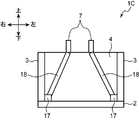
- FIG. 10 is a cross-sectional view of a turning frame 1C according to a third modified embodiment of the present invention.
- a pair of seventh reinforcing members 17 are arranged at corners where the pair of side plates 3 and the bottom plate 2 intersect so as to extend in the front-rear direction.
- the rear end portion of the seventh reinforcing member 17 is fixed to the inner surface of the rear end member 4.
- a pair of eighth reinforcing members 18 are fixed to the inner surface of the rear end member 4.
- the upper ends of the pair of eighth fixing members 18 are respectively disposed in the vicinity of the pair of lower spreaders 7 (mast coupling portions).
- the lower ends of the pair of eighth reinforcing members 18 are respectively connected to the seventh reinforcing member 17 disposed at the corners.
- the pair of eighth reinforcing members are inclined so as to extend downward from the lower spreader 7 and outward in the left-right direction. Even in such a configuration, the force applied to the lower spreader 7 can be stably transmitted to the bottom plate 2 side.
- the eighth reinforcing member 18 may be disposed so as to connect the upper portion and the lower portion of the rear end member 4.
- the eighth reinforcing member 18 in the above embodiment and the modified embodiment may be fixed to the rear side surface of the rear end member 4.
- the rear end member 4 may have a box shape including a front wall and a rear wall, which are arranged at intervals in the front-rear direction.
- a pair of lower spreaders 7 are fixed to the upper surface portion of the box-shaped rear end member 4.
- the eighth reinforcing member 18 may be disposed on the front surface portion of the front wall and the rear surface portion of the rear wall, and inside the box-shaped rear end member 4, the rear surface portion and the rear wall of the front wall. You may arrange
- an eighth reinforcing member 18 may be disposed inside the box-shaped rear end member 4 so as to fill a space between the front wall and the rear wall.
- the upper end portion of the fourth reinforcing member 14 in the above-described embodiment and modified embodiment may be arranged so as to be included in the intermediate region M as shown in FIG. It is desirable to arrange so as to extend to the upper surface portion 3T). Furthermore, when the upper end part of the 4th reinforcement member 14 and the upper end part of the 5th reinforcement member 15 are mutually connected, since force becomes easy to be transmitted between each reinforcement member, it is further desirable.
Landscapes
- Engineering & Computer Science (AREA)
- Mechanical Engineering (AREA)
- Body Structure For Vehicles (AREA)
- Jib Cranes (AREA)
Abstract
車両の重量の増加を抑えながら、作業機械の吊能力を向上させる。旋回フレーム1を側方から見たときに、ブームフット部5から旋回ベアリング22の前側部分にかけて第1の補強部材11が設けられ、ブームフット部5からマストフット部6にかけて第2の補強部材12が設けられ、マストフット部6から旋回ベアリング22の後側部分にかけて第3の補強部材13が設けられる。また、旋回フレーム1の上端部に位置するとともに旋回ベアリング22の後部の上方に位置する中間領域Mから旋回ベアリング22の前側部分にかけて第4の補強部材14が設けられ、中間領域Mから旋回ベアリング22の後側部分にかけて第5の補強部材15が設けられる。
Description
本発明は、旋回ベアリングを介して作業機械の下部走行体に旋回可能に支持された旋回フレーム、およびこれを備えた作業機械に関する。
クレーン等の作業機械においては、例えば特許文献1に開示されているように、旋回ベアリングを介して下部走行体の上部に上部旋回体が旋回可能に設けられている。上部旋回体は、旋回ベアリングに旋回可能に取り付けられた旋回フレームと、吊荷の吊り上げ等を行うブームと、マストとを備えている。作業機械は、例えば、マストの先端部に設けられた上部スプレッダと、旋回フレームに設けられた下部スプレッダとを備える。上部スプレッダと下部スプレッダとの間に掛け回された起伏ロープによりマストが起伏されることで、ブームが起伏する。
ところで、旋回フレームの前面部には、ブームの基端部を支持するブームフット部が設けられ、旋回フレームの上面部の前側部分には、マストの基端部を支持するマストフット部が設けられ、旋回フレームの上面部の後側部分には、上述の下部スプレッダが設けられている。ブームフット部、マストフット部、および、下部スプレッダには、ブームの自重や吊荷による吊荷重が作用する。
作業機械が様々な姿勢をとることによって発生する荷重や、吊荷作業によって発生する荷重は、旋回フレームに作用して、旋回フレームに変形を生じさせる。この変形は、ブームの先端部やブームの先に取り付けられたジブの先端部のたわみに影響する。その結果、作業機械の吊能力が制限されるという問題がある。
そこで、旋回フレーム全体の板厚を厚くすることで、旋回フレームの剛性を高める対策が考えられる。しかし、重量面において規制が厳しいクレーン等の作業機械において、車両の重量が大幅に増加してしまう。
本発明の目的は、車両の重量の増加を抑えながら、作業機械の吊能力を向上させることが可能な作業機械の旋回フレーム、およびこれを備えた作業機械を提供することである。
提供されるのは、作業機械の旋回フレームである。旋回フレームは、上下方向に延びる旋回中心回りに旋回可能なように、作業機械の下部走行体に旋回ベアリングを介して支持され、マストおよびブームを支持する。旋回フレームは、底板と、左右一対の側板と、後端部材と、一対のブームフット部と、一対のマストフット部と、マスト連結部と、左右一対の第1の補強部材と、左右一対の第2の補強部材と、左右一対の第3の補強部材と、左右一対の第4の補強部材と、左右一対の第5の補強部材と、を備える。底板は、底板上面部と前記旋回ベアリングが固定される底板下面部とを有する。左右一対の側板は、側板上面部と側板前端部と側板後端部とをそれぞれ有し、前記旋回フレームの前後方向に沿ってそれぞれ延びるとともに、前記旋回フレームの左右方向において前記旋回中心を挟んで互いに対向するように前記底板上面部に配置される。後端部材は、前記左右一対の側板の前記側板後端部同士を前記左右方向に沿って連結する。一対のブームフット部は、前記左右一対の側板の前記側板前端部にそれぞれ設けられ、前記ブームの基端部を支持する。一対のマストフット部は、前記左右一対の側板の前記側板上面部の前側部分にそれぞれ設けられ、前記マストの基端部を支持する。マスト連結部は、前記後端部材に設けられ、連結部材を介して前記マストに連結される。左右一対の第1の補強部材は、前記旋回フレームを前記左右方向に沿って見たときに、前記ブームフット部から前記旋回ベアリングの前側部分に向かって延びるように配設されるとともに、それぞれ前記旋回ベアリングの前側部分につながる下端部を備える。左右一対の第2の補強部材は、前記旋回フレームを前記左右方向に沿って見たときに、前記ブームフット部から前記マストフット部に向かって延びるように配設される。左右一対の第3の補強部材は、前記旋回フレームを前記左右方向に沿って見たときに、前記マストフット部から前記旋回ベアリングの後側部分に向かって延びるように配設されるとともに、それぞれ前記旋回ベアリングの後側部分につながる下端部を備える。左右一対の第4の補強部材は、前記旋回フレームを前記左右方向に沿って見たときに、前記側板の上部のうち前記旋回ベアリングの後側部分の上方に位置する中間領域から前記旋回ベアリングの前側部分に向かって延びるように配設されるとともに、それぞれ前記旋回ベアリングの前側部分につながる下端部を備える。左右一対の第5の補強部材は、前記旋回フレームを前記左右方向に沿って見たときに、前記中間領域から前記旋回ベアリングの後側部分に向かって延びるように配設されるとともに、それぞれ前記旋回ベアリングの後側部分につながる下端部を備える。
本発明によると、旋回フレームを側方から見たときに、ブームフット部から旋回ベアリングの前側部分にかけて第1の補強部材が設けられ、ブームフット部からマストフット部にかけて第2の補強部材が設けられ、マストフット部から旋回ベアリングの後側部分にかけて第3の補強部材が設けられる。また、側板の上部のうち旋回ベアリングの後側部分の上方に位置する中間領域から旋回ベアリングの前側部分にかけて第4の補強部材が設けられ、中間領域から旋回ベアリングの後側部分にかけて第5の補強部材が設けられる。
ブームの自重や吊荷により、ブームフット部と旋回ベアリングの前側部分との間には圧縮荷重が作用するが、第1の補強部材によりこれらの間の部分の剛性が向上するので、これらの間の部分における変形が抑制される。また、このときに、ブームフット部とマストフット部との間には圧縮荷重が作用するが、第2の補強部材によりこれらの間の部分の剛性が向上するので、これらの間の部分における変形が抑制される。また、このときに、マストフット部と旋回ベアリングの後側部分との間には引張荷重が作用するが、第3の補強部材によりこれらの間の部分の剛性が向上するので、これらの間の部分における変形が抑制される。また、このときに、中間領域と旋回ベアリングの前側部分との間には圧縮荷重が作用するが、第4の補強部材によりこれらの間の部分の剛性が向上するので、これらの間の部分における変形が抑制される。また、このときに、中間領域と旋回ベアリングの後側部分との間には引張荷重が作用するが、第5の補強部材によりこれらの間の部分の剛性が向上するので、これらの間の部分における変形が抑制される。
このように、旋回フレームの変形を抑制することができるので、作業機械の吊能力を向上させることができる。このとき、5つの補強部材で荷重が作用する箇所の剛性が効率的に向上されているので、補強部材の追加による重量増加が最小限に抑えられる。よって、車両の重量の増加を抑えながら、作業機械の吊能力を向上させることができる。
以下、本発明の好適な一実施形態について、図面を参照しつつ説明する。
(クレーンの構成)
本発明の実施形態による作業機械の旋回フレーム1は、作業機械であるクレーン20に設けられている。図1は、本実施形態に係るクレーン20の側面図である。図2は、本実施形態に係る旋回フレーム1を前方から見た正面図である。なお、各図では、旋回フレーム1の前後、左右および上下方向を矢印で付している。クレーン20が図1のような姿勢とされているとき、旋回フレーム1の前後、左右および上下方向は、クレーン20の前後、左右および上下方向と一致している。クレーン20は、後述するブーム32により、吊荷Lを吊り上げる作業(荷役作業)等を行う。
本発明の実施形態による作業機械の旋回フレーム1は、作業機械であるクレーン20に設けられている。図1は、本実施形態に係るクレーン20の側面図である。図2は、本実施形態に係る旋回フレーム1を前方から見た正面図である。なお、各図では、旋回フレーム1の前後、左右および上下方向を矢印で付している。クレーン20が図1のような姿勢とされているとき、旋回フレーム1の前後、左右および上下方向は、クレーン20の前後、左右および上下方向と一致している。クレーン20は、後述するブーム32により、吊荷Lを吊り上げる作業(荷役作業)等を行う。
クレーン20は、下部走行体21と、旋回ベアリング22と、上部旋回体23と、を備える。下部走行体21は、クレーン20を走行させる部分である。下部走行体21は、例えばクローラ式であり、ホイール式でもよい。上部旋回体23は、旋回ベアリング22を介して下部走行体21の上部に旋回可能に設けられる。
上部旋回体23は、旋回フレーム1と、ブーム32と、マスト33と、を備える。以下、旋回フレーム1のブーム32側を前側、旋回フレーム1のうちブーム32とは反対側を後側とする。
旋回フレーム1は、上下方向に延びる旋回中心22c回りに旋回可能なように、クレーン20の下部走行体11に旋回ベアリング22を介して支持されている。旋回フレーム1は、ブーム32およびマスト33を起伏可能に支持する。旋回ベアリング22は、旋回フレーム1に固定されるアウタレース22oと、下部走行体21に固定されるインナレース22iと、を備える(図2)。なお、アウタレース22oが下部走行体21に固定され、インナレース22iが旋回フレーム1に固定されてもよい。旋回フレーム1は、旋回ベアリング22の上面に取り付けられた、環状で回転しない座面板22a(図2)の上面に複数のボルトで固定されている。旋回フレーム1の左右には、図示しない左フレームや右フレームなどが設けられる。例えば、右フレーム上には、キャブ(運転室)などが設けられる。また、旋回フレーム1の後側には、図示しないカウンタウエイトが分解可能に設けられる。カウンタウエイトは、クレーン20の吊荷Lとバランスをとるためのおもりである。なお、旋回フレーム1は、例えば旋回ベアリング22の後部を境に前後に分割可能な構成であってもよい。
ブーム32は、例えばラチス構造を有し、吊荷Lの吊り上げ等を行うための起伏部材である。ブーム32は、旋回フレーム1の前端部(後記の側板前端部3F)において、旋回フレーム1に起伏可能に取り付けられている。
マスト33は、ブーム32の後側の位置に設けられている。マスト33の先端部と、ブーム32の先端部とは、ガイライン34を介して互いに連結されている。また、マスト33の先端部に設けられた上部スプレッダ39と、旋回フレーム1の後部に設けられた下部スプレッダ7(マスト連結部)とは、ブーム起伏ロープ35(連結部材)を介して互いに連結されている。旋回フレーム1に設けられたウインチ(図示せず)がブーム起伏ロープ35を巻取り及び巻出しすることで、マスト33が起伏する結果、ブーム32が起伏する。
旋回フレーム1の前面部(後記の側板前端部3F)には、ブーム32の基端部が取り付けられ、ブーム32の基端部を支持するブームフット部5が設けられている。また、旋回フレーム1の上面(後記の側板上面部3T)の前側部分には、マスト33の基端部が取り付けられ、マスト33の基端部を支持するマストフット部6が設けられている。また、旋回フレーム1の上面の後側部分(後記の後端部材4)には、上述した下部スプレッダ7が設けられている。
(旋回フレームの構成)
図2に示すように、旋回フレーム1は、旋回ベアリング22の上方に水平に配置された底板2を有している。底板2は、旋回ベアリング22の上面に取り付けられた座面板22aの上面に取り付けられている。ここで、底板2のうち座面板22aが固定される部分が、ベアリング装着部と定義される。底板2は、底板上面部2Aと、旋回ベアリング22が座面板22aを介して固定される底板下面部2Bとを有する(図2)。なお、底板2の後端部は、図3の旋回ベアリング22の後端部の近傍に配置されてもよく、後記の第7の補強部材17の後端部の近傍まで後方に延びるように配置されてもよい。すなわち、底板2は、少なくとも旋回ベアリング22の上方に配置されればよい。
図2に示すように、旋回フレーム1は、旋回ベアリング22の上方に水平に配置された底板2を有している。底板2は、旋回ベアリング22の上面に取り付けられた座面板22aの上面に取り付けられている。ここで、底板2のうち座面板22aが固定される部分が、ベアリング装着部と定義される。底板2は、底板上面部2Aと、旋回ベアリング22が座面板22aを介して固定される底板下面部2Bとを有する(図2)。なお、底板2の後端部は、図3の旋回ベアリング22の後端部の近傍に配置されてもよく、後記の第7の補強部材17の後端部の近傍まで後方に延びるように配置されてもよい。すなわち、底板2は、少なくとも旋回ベアリング22の上方に配置されればよい。
また、旋回フレーム1は、左右一対の側板3を有している。一対の側板3は、旋回フレーム1の左右方向に所定の間隔をあけて、旋回中心22cを挟んで互いに対向するように底板2の底板上面部2Aにそれぞれ立てて設けられている。一対の側板3は、それぞれが旋回フレーム1の前後方向に沿って延びるように配置されている。一対の側板3は、それぞれ、側板上面部3T(図2)と、側板前端部3F(図2)と、側板後端部3B(図4A参照)とを有している。側板3の下端部は、底板2の底板上面部2Aに溶接されている。
また、旋回フレーム1は、前板(図示なし)と、後端部材4(図2、図9参照)と、を有する。前板は、旋回フレーム1の前後方向の前側部分において底板2の底板上面部2Aに立てて設けられ、前板と後端部材4とは前後方向に面するように配置されている。後端部材4は、クレーン20の前後方向の後側において底板2の底板上面部2Aに設けられ、一対の側板3の後端(側板後端部3B)同士を左右方向に沿って連結する。なお、図2においては、前板の図示を省略している。
一対の側板3の前面(側板前端部3F)には、一対のブームフット部5がそれぞれ設けられ、一対の側板3の上面(側板上面部3T)には、一対のマストフット部6がそれぞれ設けられている(図2)。また、後端部材4の上面には、一対の下部スプレッダ7が設けられている。
図3は、本実施形態に係る旋回フレーム1を左側から見た断面図であって、旋回フレーム1の左右方向の中央部を通り、前後方向および上下方向に沿った断面図である。図4Aおよび図4Bは、本実施形態に係る旋回フレーム1の上面図である。なお、図3~図4Bでは、旋回フレーム1の一部の部材を省略している。特に、図3~図4Bでは、底板2の図示を省略している。図3の矢印で示すように、ブームフット部5、マストフット部6、および、下部スプレッダ7には、ブーム32の自重や吊荷Lによる吊荷重が作用する。これらの荷重は、ブームフット部5に下向きかつ後向きに作用し、マストフット部6に下向きかつ前向きに作用し、下部スプレッダ7に上向きに作用する。これらの荷重は、旋回フレーム1から旋回ベアリング22に伝達される。
クレーン20が様々な姿勢をとることで発生する荷重や、吊荷作業によって発生する荷重は、旋回フレーム1に作用して、旋回フレーム1に変形を生じさせる。この変形は、ブーム32の先端部やブーム32の先に取り付けられた不図示のジブの先端部のたわみに影響する。その結果、クレーン20の吊能力が制限される。
そこで、本実施形態の旋回フレーム1は、図3~図4Bに示すように、左右一対の第1の補強部材11と、左右一対の第2の補強部材12と、左右一対の第3の補強部材13と、左右一対の第4の補強部材14と、左右一対の第5の補強部材15と、を有している。本実施形態において、これらの補強部材11~15は、金属製であり、円筒や角筒等の中空の管状であるが、板状や円柱状、角柱状であってもよい。また、これらの補強部材11~15は、始めから旋回フレーム1に備えられて、他の部材と一体的に設けられていてもよいし、後付けで旋回フレーム1に取り付けられてもよい。
一対の第1の補強部材11は、図3に示すように、旋回フレーム1を左右方向に沿って側方から見たときに、ブームフット部5から旋回ベアリング22の上面部の前側部分(旋回ベアリング22の前側部分)にかけて直線状に延びるように設けられている。図4Aに示すように、第1の補強部材11は、ブームフット部5と旋回ベアリング22の上面部の前側部分とをつなぐように配置されている。第1の補強部材11の上端部(基端部)は、側板3の内面に固定され、第1の補強部材11の下端部(旋回ベアリング22側の先端部)は、底板2に固定されている。この結果、第1の補強部材11の下端部は、底板2および座面板22aを介して、旋回ベアリング22の上面部の前側部分につながっている。第1の補強部材11の下端部は、左右一対の側板3から左右方向の内側にそれぞれ間隔をおいた位置で底板2に固定されている。なお、他の実施形態において、旋回ベアリング22の上面に取り付けられた座面板22aが底板2を貫通しており、第1の補強部材11の下端部が当該座面板22aに固定されてもよい。更に、他の実施形態において、旋回ベアリング22の上面部と側面部とを囲むように座面板22aが設けられ、第1の補強部材11の下端部が、底板2および座面板22aを介して、旋回ベアリング22の上面部に繋がっている態様でもよい。また、第1の補強部材11の下端部は、旋回ベアリング22の上面部につながっている構成に限定されるものではなく、旋回ベアリング22の側面部につながっているものでもよい。すなわち、第1の補強部材11の延長線上に旋回ベアリング22が配置されていればよい。なお、図4Aにおいては、底板2、前板および後端部材4の図示を省略している。また、補強部材の固定手段は、ボルト、溶接など公知の任意の接合手段を用いることができる。
一対の第2の補強部材12は、図3に示すように、旋回フレーム1を左右方向に沿って側方から見たときに、ブームフット部5からマストフット部6にかけて直線状に延びるように設けられている。図4Aに示すように、第2の補強部材12は、ブームフット部5とマストフット部6とをつなぐように配置されている。第2の補強部材12の側面は、上端から下端にわたって側板3の内面に固定されている。
一対の第3の補強部材13は、図3に示すように、旋回フレーム1を左右方向に沿って側方から見たときに、マストフット部6から旋回ベアリング22の上面部の後側部分(旋回ベアリング22の後側部分)にかけて直線状に延びるように設けられている。図4Aに示すように、第3の補強部材13は、マストフット部6と旋回ベアリング22の上面部の後側部分とをつなぐように配置されている。第3の補強部材13の上端部(基端部)は、側板3の内面に固定され、第3の補強部材13の下端部(旋回ベアリング22側の先端部)は、底板2に固定されている。この結果、第3の補強部材13の下端部は、底板2および座面板22aを介して、旋回ベアリング22の上面部の後側部分につながっている。第3の補強部材13の下端部は、左右一対の側板3から左右方向の内側にそれぞれ間隔をおいた位置で底板2に固定されている。なお、他の実施形態において、座面板22aが底板2を貫通しており、第3の補強部材13の下端部が当該座面板22aに固定されてもよい。更に、他の実施形態において、旋回ベアリング22の上面部と側面部とを囲むように座面板22aが設けられ、第3の補強部材13の下端部が、底板2および座面板22aを介して、旋回ベアリング22の上面部に繋がっている態様でもよい。また、第3の補強部材13の下端部は、旋回ベアリング22の上面部につながっている構成に限定されるものではなく、旋回ベアリング22の側面部につながっているものでもよい。すなわち、第3の補強部材13の延長線上に旋回ベアリング22が配置されていればよい。
一対の第4の補強部材14は、図3に示すように、旋回フレーム1を左右方向に沿って側方から見たときに、旋回フレーム1の中間領域Mから旋回ベアリング22の上面部の前側部分(旋回ベアリング22の前側部分)にかけて直線状に延びるように設けられている。なお、旋回フレーム1の中間領域Mとは、旋回フレーム1の上端部(側板上面部3T近傍)に位置するとともに旋回ベアリング22の後端部の上方に位置する領域である。図4Bに示すように、第4の補強部材14は、中間領域Mと旋回ベアリング22の上面部の前側部分(旋回ベアリング22の前側部分)とをつなぐように配置されている。第4の補強部材14の側面は、上端から下端にわたって側板3の内面に固定されている。また、第4の補強部材14の下端部(旋回ベアリング22側の先端部)は、底板2に固定されている。この結果、第4の補強部材14の下端部は、底板2および座面板22aを介して、旋回ベアリング22の上面部の前側部分につながっている。なお、他の実施形態において、座面板22aが底板2を貫通しており、第4の補強部材14の下端部が当該座面板22aに固定されていてもよい。なお、図4Bにおいては、底板2、前板および後端部材4の図示を省略している。更に、他の実施形態において、旋回ベアリング22の上面部と側面部とを囲むように座面板22aが設けられ、第4の補強部材14の下端部が、底板2および座面板22aを介して、旋回ベアリング22の上面部に繋がっている態様でもよい。また、第4の補強部材14の下端部は、旋回ベアリング22の上面部につながっている構成に限定されるものではなく、旋回ベアリング22の側面部につながっているものでもよい。すなわち、第4の補強部材14の延長線上に旋回ベアリング22が配置されていればよい。
一対の第5の補強部材15は、図3に示すように、旋回フレーム1を左右方向に沿って側方から見たときに、中間領域Mから旋回ベアリング22の上面部の後側部分(旋回ベアリング22の後側部分)にかけて直線状に延びるように設けられている。図4Bに示すように、第5の補強部材15は、中間領域Mと旋回ベアリング22の上面部の後側部分とをつなぐように配置されている。第5の補強部材15の側面は、上端から下端にわたって側板3の内面に固定されている。なお、第5の補強部材15の下端部は、底板2に固定されてもよく、後記の第7の補強部材17の前端部に固定されてもよい。いずれの場合も、第5の補強部材15の下端部は、少なくとも底板2および座面板22aを介して、旋回ベアリング22の上面部につながっている。更に、他の実施形態において、旋回ベアリング22の上面部と側面部とを囲むように座面板22aが設けられ、第5の補強部材15の下端部が、底板2および座面板22aを介して、旋回ベアリング22の上面部に繋がっている態様でもよい。また、第5の補強部材15の下端部は、旋回ベアリング22の上面部につながっている構成に限定されるものではなく、旋回ベアリング22の側面部につながっているものでもよい。すなわち、第5の補強部材15の延長線上に旋回ベアリング22が配置されていればよい。
ブーム32の自重や吊荷Lにより、ブームフット部5と旋回ベアリング22の上面部の前側部分との間には圧縮荷重が作用するが、第1の補強部材11によりこれらの間の部分の剛性が向上するので、これらの間の部分における変形が抑制される。また、このときに、ブームフット部5とマストフット部6との間には圧縮荷重が作用するが、第2の補強部材12によりこれらの間の部分の剛性が向上するので、これらの間の部分における変形が抑制される。また、このときに、マストフット部6と旋回ベアリング22の上面部の後側部分との間には引張荷重が作用するが、第3の補強部材13によりこれらの間の部分の剛性が向上するので、これらの間の部分における変形が抑制される。
また、このときに、中間領域Mと旋回ベアリング22の上面部の前側部分との間には圧縮荷重が作用するが、第4の補強部材14によりこれらの間の部分の剛性が向上するので、これらの間の部分における変形が抑制される。また、このときに、中間領域Mと旋回ベアリング22の上面の後部との間には引張荷重が作用するが、第5の補強部材15によりこれらの間の部分の剛性が向上するので、これらの間の部分における変形が抑制される。
このように、本実施形態では、旋回フレーム1にかかる荷重が旋回ベアリング22の前側部分および後側部分に安定して伝達されながら、旋回フレーム1の変形を抑制することができるので、クレーン20の吊能力を向上させることができる。このとき、5つの補強部材11~15で荷重が作用する箇所の剛性を効率的に向上させているので、補強部材11~15の追加による重量増加を最小限に抑えることができる。よって、重量の増加を抑えながら、クレーン20の吊能力を向上させることができる。
更に、旋回フレーム1は、図3および図4Bに示すように、左右一対の第6の補強部材16と、左右一対の第7の補強部材17と、左右一対の第8の補強部材18と、を有している。本実施形態において、これら補強部材16~18は、金属製であり、円筒や角筒等の中空の管状であるが、板状や円柱状、角柱状であってもよい。また、これら補強部材16~18は、始めから旋回フレーム1に備えられて、他の部材と一体的に設けられていてもよいし、後付けで旋回フレーム1に取り付けられてもよい。
一対の第6の補強部材16は、図3に示すように、旋回フレーム1を左右方向に沿って側方から見たときに、中間領域Mから旋回フレーム1の後面部の上部(後端部材4の上側部分)にかけて直線状に延びるように設けられている。図3、図4Bに示すように、第6の補強部材16は、中間領域Mと旋回フレーム1の後面部の上部(後端部材4の上側部分)とをつなぐように配置されている。第6の補強部材16の側面は、前端から後端にわたって側板3の内面に固定されている。なお、一対の第6の補強部材16は、旋回フレーム22を前記左右方向に沿って見たときに、中間領域Mの上端部から後端部材4の上端部に向かって延びるように配設されるとともに、中間領域Mと後端部材4の上端部とをつなぐように配置されることが、より好ましい。
一対の第7の補強部材17は、図3に示すように、旋回フレーム1を左右方向に沿って側方から見たときに、第6の補強部材16よりも下方の位置であって旋回ベアリング22の後側部分の上方の位置から旋回フレーム1の後面部の下部(後端部材4の下側部分)にかけて直線状に延びるように設けられている。図4Bにおいて、第7の補強部材17は、第6の補強部材16よりも紙面の奥側に位置しており、側板3のうち第6の補強部材16よりも下方の位置であって旋回ベアリング22の上方の位置と後端部材4の下側部分とを水平方向に沿ってつなぐように配置されている。第7の補強部材17の側面は、前端から後端にわたって側板3の内面に固定されている。また、少なくとも第7の補強部材17の前端部は、底板2に固定されている。なお、底板2が旋回フレーム1の後端部まで延びている場合には、第7の補強部材17の下面部が前後方向に沿って底板2に固定されてもよい。また、底板2が旋回フレーム1の後端部まで延びていない場合には、底板2の代わりに、一対の側板3同士をつなぐ梁部材が配置されてもよい。なお、一対の第7の補強部材17は、旋回フレーム1を左右方向に沿って見たときに、第6の補強部材16よりも下方の位置であって旋回ベアリング22の後側部分の上方の位置から後端部材4の下端部に向かって延びるように配設されるとともに、側板3のうち第6の補強部材16よりも下方の位置であって旋回ベアリング22の後側部分の上方の位置と後端部材4の下端部とをつなぐように配置されることが、より好ましい。
一対の第8の補強部材18は、図3に示すように、旋回フレーム1を左右方向に沿って側方から見たときに、旋回フレーム1の後面部の上側部分(後端部材4の上側部分)から旋回フレーム1の後面部の下側部分(後端部材4の下側部分)にかけて直線状に上下方向に沿って延びるように設けられている。図4Bにおいて、第8の補強部材18は、第6の補強部材16よりも紙面の奥側において、紙面に直交する方向に延びており、旋回フレーム1の後面部の上側部分と旋回フレーム1の後面部の下側部分とをつなぐように配置されている。第8の補強部材18の側面は、上端から下端にわたって側板3の内面に固定されている。また、第8の補強部材18の後面部は、後端部材4の前面に固定されている。なお、第8の補強部材18は、旋回フレーム22を左右方向に沿って見たときに、上下方向に沿って延びるように後端部材4に固定され、後端部材4の上端部と下端部とをつなぐように配置されることが、より好ましい。
図3に示すように、吊荷Lにより、下部スプレッダ7には上向きの力が作用する。これにより、中間領域Mと旋回フレーム1の後面部の上側部分との間には水平方向に沿って圧縮荷重が作用するが、第6の補強部材16によりこれらの間の部分の剛性が向上するので、これらの間の部分における変形が抑制される。また、このときに、旋回ベアリング22の上面部の後側部分と旋回フレーム1の後面部の下側部分との間には水平方向に沿って引張荷重が作用するが、第7の補強部材17によりこれらの間の部分の剛性が向上するので、これらの間の部分における変形が抑制される。また、このときに、旋回フレーム1の後面部の上側部分と旋回フレーム1の後面部の下側部分との間には上下方向に沿って引張荷重が作用するが、第8の補強部材18によりこれらの間の部分の剛性が向上するので、これらの間の部分における変形が抑制される。
また、吊荷Lがないときに、カウンタウエイトにより、旋回フレーム1の後部には下向きの力が作用する。これにより、中間領域Mと旋回フレーム1の後面部の上側部分との間には水平方向に沿って引張荷重が作用するが、第6の補強部材16によりこれらの間の部分の剛性が向上するので、これらの間の部分における変形が抑制される。また、このときに、旋回ベアリング22の上面部の後側部分と旋回フレーム1の後面部の下側部分との間に水平方向に沿って圧縮荷重が作用するが、第7の補強部材17によりこれらの間の部分の剛性が向上するので、これらの間の部分における変形が抑制される。また、このときに、旋回フレーム1の後面部の上側部分と旋回フレーム1の後面部の下側部分との間に上下方向に沿って引張荷重が作用するが、第8の補強部材18によりこれらの間の部分の剛性が向上するので、これらの間の部分における変形が抑制される。
このように、本実施形態では、旋回フレーム1にかかる荷重が旋回ベアリング22の前側部分および後側部分に安定して伝達されながら、旋回フレーム1の変形をさらに抑制することができるので、クレーン20の吊能力をさらに向上させることができる。このとき、3つの補強部材16~18で荷重が作用する箇所の剛性を効率的に向上させているので、補強部材16~18の追加による重量増加を最小限に抑えることができる。
また、本実施形態では、図3に示すように、旋回フレーム1を左右方向に沿って見たときに第3の補強部材13と第4の補強部材14とが交差する部分(交差部)において、両者が接合されている。両者を接合することで、接合箇所における旋回フレーム1の剛性をさらに向上させることができる。これにより、旋回フレーム1の変形をさらに抑制することができるので、クレーン20の吊能力をさらに向上させることができる。
(変形実施形態)
次に、本発明の変形実施形態について説明する。図5は、本発明の第1変形実施形態に係る旋回フレーム1Aの上面図である。なお、図5では、前板、底板および後端部材の図示を省略している。図4Aおよび図4Bにおいては、側板3は、旋回ベアリング22よりも左右方向の外側に位置しているが、第1変形実施形態では、図5に示すように、側板3は、旋回ベアリング22の左右端部の上方に位置している。一対の第3の補強部材13は、その側面が上端から下端にわたって一対の側板3の内面にそれぞれ固定されている。なお、第3の補強部材13の下端部は、先の実施形態と同様に底板2に固定されている。一対の第1の補強部材11は、一対の第2の補強部材12および一対の第3の補強部材13よりも紙面の奥側に位置しているが、同様に、第1の補強部材11の側面は上端から下端にわたって側板3の内面に固定されている。また、第1の補強部材11の下端部は、先の実施形態と同様に底板2に固定されている。なお、先の実施形態と同様に、座面板22aが底板2を貫通しており、第1の補強部材11および第3の補強部材13の下端部がそれぞれ座面板22aに固定されてもよい。
次に、本発明の変形実施形態について説明する。図5は、本発明の第1変形実施形態に係る旋回フレーム1Aの上面図である。なお、図5では、前板、底板および後端部材の図示を省略している。図4Aおよび図4Bにおいては、側板3は、旋回ベアリング22よりも左右方向の外側に位置しているが、第1変形実施形態では、図5に示すように、側板3は、旋回ベアリング22の左右端部の上方に位置している。一対の第3の補強部材13は、その側面が上端から下端にわたって一対の側板3の内面にそれぞれ固定されている。なお、第3の補強部材13の下端部は、先の実施形態と同様に底板2に固定されている。一対の第1の補強部材11は、一対の第2の補強部材12および一対の第3の補強部材13よりも紙面の奥側に位置しているが、同様に、第1の補強部材11の側面は上端から下端にわたって側板3の内面に固定されている。また、第1の補強部材11の下端部は、先の実施形態と同様に底板2に固定されている。なお、先の実施形態と同様に、座面板22aが底板2を貫通しており、第1の補強部材11および第3の補強部材13の下端部がそれぞれ座面板22aに固定されてもよい。
また、図6は、本発明の第2変形実施形態に係る旋回フレーム1Bの上面図である。なお、図6では、前板、底板および後端部材の図示を省略している。第2変形実施形態では、図6に示すように、側板3は、旋回ベアリング22の左右端部よりも内側に位置している。一対の第3の補強部材13は、それぞれ一対の側板3の外面側に配置され、第3の補強部材13の側面は上端から下端にわたって側板3の外面部に固定されている。第3の補強部材13の下端部は、先の実施形態と同様に底板2に固定されている。一対の第1の補強部材11も同様に、一対の側板3の外面側にそれぞれ配置され、第1の補強部材11の側面は上端から下端にわたって側板3の外面部に固定されている。第1の補強部材11の下端部は、先の実施形態と同様に底板2に固定されている。第4から第8の補強部材14~18についても、それぞれ側板3の外面に固定されている。この場合、不図示の後端部材4(図9参照)が、一対の側板3よりも左右方向の外側に突出するように配置され、当該後端部材4に、第6の補強部材16および第7の補強部材17の後端部、第8の補強部材18の後面部がそれぞれ固定されてもよい。
また、旋回ベアリング22に対する側板3の位置によっては、各補強部材11~18は、側板3の内面側および外面側にそれぞれ設けられていてもよい。この場合、各補強部材11~18は、側板3の内面および外面にそれぞれ固定されていてもよい。また、各補強部材11~18の一部は、側板3に対して離隔して配置されていてもよい。また、第1の補強部材11、第3の補強部材13、第4の補強部材14、第7の補強部材17は、底板2に固定される構成に限定されず、底板2に当接するように側板3に固定されてもよい。また、第5の補強部材15の下端部は、底板2に当接するように側板3に固定されていてもよい。
(フレーム変形評価)
次に、本実施形態の旋回フレーム1の変形と、従来の旋回フレーム(従来構造)201の変形とをシミュレーションにより評価した。図7Aは、本発明の一実施形態に係る旋回フレーム1の拡大側面図である。図7Bは、従来構造の旋回フレーム201の拡大側面図である。評価に用いた本実施形態に係る旋回フレーム1は、図7Aに示すように、第1から第8の補強部材11~18のうち、側板3の外面に固定された第1から第5の補強部材11~15を備える。一方、評価に用いた従来構造のフレーム201は、図7Bに示すように、側板3の外面に固定され、マストフット部6から旋回ベアリング22の中央部にかけて直線状に延びるように設けられた補強部材202を備える。なお、シミュレーション評価では、本実施形態における第1から第5の補強部材11~15の総重量と、従来構造201の補強部材202の総重量とを同じに設定した。
次に、本実施形態の旋回フレーム1の変形と、従来の旋回フレーム(従来構造)201の変形とをシミュレーションにより評価した。図7Aは、本発明の一実施形態に係る旋回フレーム1の拡大側面図である。図7Bは、従来構造の旋回フレーム201の拡大側面図である。評価に用いた本実施形態に係る旋回フレーム1は、図7Aに示すように、第1から第8の補強部材11~18のうち、側板3の外面に固定された第1から第5の補強部材11~15を備える。一方、評価に用いた従来構造のフレーム201は、図7Bに示すように、側板3の外面に固定され、マストフット部6から旋回ベアリング22の中央部にかけて直線状に延びるように設けられた補強部材202を備える。なお、シミュレーション評価では、本実施形態における第1から第5の補強部材11~15の総重量と、従来構造201の補強部材202の総重量とを同じに設定した。
評価は、ブーム圧縮力が最大となる条件(条件1)と、起伏ロープの張力が最大となる条件(条件2)とでそれぞれ行った。ここで、ブーム圧縮力が最大となる条件(条件1)とは、吊荷Lによりブーム32に発生する軸力が最大となり、ブームフット部5に作用する荷重が最大となる条件である。起伏ロープの張力が最大となる条件(条件2)とは、吊荷Lを吊ったときに上部旋回体23が前向きに倒れるモーメントが最大となり、旋回フレーム全体に最大の曲げが生じる条件である。
図8Aは、条件1において、ブームフット部5、マストフット部6、および、下部スプレッダ7に作用する荷重の大きさ及び角度を示す、旋回フレームの側面図である。また、図8Bは、条件2において、ブームフット部5、マストフット部6、および、下部スプレッダ7に作用する荷重の大きさ及び角度を示す、旋回フレームの側面図である。また、図9は、評価の測定点を示す、旋回フレームの斜視図である。
図9に示すように、左側のブームフット部5に測定点A、右側のブームフット部5に測定点B、右側の下部スプレッダ7に測定点C、左側の下部スプレッダ7に測定点Dをそれぞれ設けて、各測定点における左右方向(x方向)の変位、および、前後方向(y方向)の変位を評価した。評価結果を表1に示す。

表1から、本実施形態の旋回フレーム1では、その変形が、従来構造201に比べて、条件1においては3.8~4.5%、条件2においては3.6~4.4%、抑制されていることがわかる。
(効果)
以上に述べたように、本発明に係る旋回フレーム1、1Aおよび1Bによると、旋回フレーム1を左右方向に沿って側方から見たときに、ブームフット部5から旋回ベアリング22の前側部分に向かって延びるように一対の第1の補強部材11が設けられ、ブームフット部5からマストフット部6に向かって延びるように第2の補強部材12が設けられ、マストフット部6から旋回ベアリング22の後側部分に向かって延びるように第3の補強部材13が設けられる。また、旋回フレーム1の側板上面部3Tのうち旋回ベアリング22の後端部の上方に位置する中間領域Mから旋回ベアリング22の前側部分に向かって延びるように第4の補強部材14が設けられ、中間領域Mから旋回ベアリング22の後側部分に向かって延びるように第5の補強部材15が設けられる。そして、ブームフット部5と旋回ベアリング22の前側部分とをつなぐように第1の補強部材11が配置され、ブームフット部5とマストフット部6とをつなぐように第2の補強部材12が配置され、マストフット部6と旋回ベアリング22の後側部分とをつなぐように第3の補強部材13が配置される。また、中間領域Mと旋回ベアリング22の前側部分とをつなぐように第4の補強部材14が配置され、中間領域Mと旋回ベアリング22の後側部分とをつなぐように第5の補強部材15が配置される。
以上に述べたように、本発明に係る旋回フレーム1、1Aおよび1Bによると、旋回フレーム1を左右方向に沿って側方から見たときに、ブームフット部5から旋回ベアリング22の前側部分に向かって延びるように一対の第1の補強部材11が設けられ、ブームフット部5からマストフット部6に向かって延びるように第2の補強部材12が設けられ、マストフット部6から旋回ベアリング22の後側部分に向かって延びるように第3の補強部材13が設けられる。また、旋回フレーム1の側板上面部3Tのうち旋回ベアリング22の後端部の上方に位置する中間領域Mから旋回ベアリング22の前側部分に向かって延びるように第4の補強部材14が設けられ、中間領域Mから旋回ベアリング22の後側部分に向かって延びるように第5の補強部材15が設けられる。そして、ブームフット部5と旋回ベアリング22の前側部分とをつなぐように第1の補強部材11が配置され、ブームフット部5とマストフット部6とをつなぐように第2の補強部材12が配置され、マストフット部6と旋回ベアリング22の後側部分とをつなぐように第3の補強部材13が配置される。また、中間領域Mと旋回ベアリング22の前側部分とをつなぐように第4の補強部材14が配置され、中間領域Mと旋回ベアリング22の後側部分とをつなぐように第5の補強部材15が配置される。
ブーム32の自重や吊荷Lにより、ブームフット部5と旋回ベアリング22の前側部分との間には圧縮荷重が作用するが、第1の補強部材11によりこれらの間の部分の剛性が向上するので、これらの間の部分における変形が抑制される。また、このときに、ブームフット部5とマストフット部6との間には圧縮荷重が作用するが、第2の補強部材12によりこれらの間の部分の剛性が向上するので、これらの間の部分における変形が抑制される。また、このときに、マストフット部6と旋回ベアリング22の後側部分との間には引張荷重が作用するが、第3の補強部材13によりこれらの間の部分の剛性が向上するので、これらの間の部分における変形が抑制される。また、このときに、中間領域Mと旋回ベアリング22の前側部分との間には圧縮荷重が作用するが、第4の補強部材14によりこれらの間の部分の剛性が向上するので、これらの間の部分における変形が抑制される。また、このときに、中間領域Mと旋回ベアリング22の後側部分との間には引張荷重が作用するが、第5の補強部材15によりこれらの間の部分の剛性が向上するので、これらの間の部分における変形が抑制される。
このように、旋回フレーム1の変形を抑制することができるので、クレーン20の吊能力を向上させることができる。このとき、5つの補強部材11~15で荷重が作用する箇所の剛性を効率的に向上させているので、補強部材11~15の追加による重量増加を最小限に抑えることができる。よって、重量の増加を抑えながら、クレーン20の吊能力を向上させることができる。
また、旋回フレーム1を左右方向に沿って側方から見たときに、中間領域Mから旋回フレーム1の後面部の上側部部分にかけて第6の補強部材16が設けられ、旋回ベアリング22の上面部の後側部分から旋回フレーム1の後面部の下側部分にかけて第7の補強部材17が設けられ、旋回フレーム1の後面部の上側部分から旋回フレーム1の後面部の下側部分にかけて第8の補強部材18が設けられる。そして、中間領域Mと旋回フレーム1の後面部の上側部分とをつなぐように第6の補強部材16が配置され、旋回ベアリング22の上面部の後側部分と旋回フレーム1の後面部の下側部分とをつなぐように第7の補強部材17が配置され、旋回フレーム1の後面部の上側部分と旋回フレーム1の後面部の下側部分とをつなぐように第8の補強部材18が配置される。
吊荷Lにより、下部スプレッダ7には上向きの力が作用する。これにより、中間領域Mと旋回フレーム1の後面分の上側部分との間には圧縮荷重が作用するが、第6の補強部材16によりこれらの間の部分の剛性が向上するので、これらの間の部分における変形が抑制される。また、このときに、旋回ベアリング22の上面部の後側部分と旋回フレーム1の後面部の下側部分との間には引張荷重が作用するが、第7の補強部材17によりこれらの間の部分の剛性が向上するので、これらの間の部分における変形が抑制される。また、このときに、旋回フレーム1の後面部の上側部分と旋回フレーム1の後面部の下側部分との間には引張荷重が作用するが、第8の補強部材18によりこれらの間の部分の剛性が向上するので、これらの間の部分における変形が抑制される。
また、吊荷Lがないときに、カウンタウエイトにより、旋回フレーム1の後部には下向きの力が作用する。これにより、中間領域Mと旋回フレーム1の後面部の上側部分との間には引張荷重が作用するが、第6の補強部材16によりこれらの間の部分の剛性が向上するので、これらの間の部分における変形が抑制される。また、このときに、旋回ベアリング22の上面部の後側部分と旋回フレーム1の後面部の下側部分との間に圧縮荷重が作用するが、第7の補強部材17によりこれらの間の部分の剛性が向上するので、これらの間の部分における変形が抑制される。また、このときに、旋回フレーム1の後面部の上側部分と旋回フレーム1の後面部の下側部分との間に引張荷重が作用するが、第8の補強部材18によりこれらの間の部分の剛性が向上するので、これらの間の部分における変形が抑制される。
このように、旋回フレーム1の変形をさらに抑制することができるので、クレーン20の吊能力をさらに向上させることができる。このとき、3つの補強部材16~18で荷重が作用する箇所の剛性を効率的に向上させているので、補強部材16~18の追加による重量増加を最小限に抑えることができる。
また、第3の補強部材13と第4の補強部材14とが交差する部分(交差部)において、両者を接合することで、接合箇所における旋回フレーム1の剛性をさらに向上させることができる。これにより、旋回フレーム1の変形をさらに抑制することができるので、クレーン20の吊能力をさらに向上させることができる。
以上、本発明の実施形態を説明したが、具体例を例示したに過ぎず、特に本発明を限定するものではなく、具体的構成などは、適宜設計変更可能である。また、発明の実施の形態に記載された、作用及び効果は、本発明から生じる最も好適な作用及び効果を列挙したに過ぎず、本発明による作用及び効果は、本発明の実施の形態に記載されたものに限定されるものではない。
なお、図10は、本発明の第3変形実施形態に係る旋回フレーム1Cの断面図である。本変形実施形態では、一対の側板3と底板2とが交差する角部に、一対の第7の補強部材17が前後方向に延びるように配置されている。第7の補強部材17の後端部は、後端部材4の内面に固定されている。更に、後端部材4の内面には、一対の第8の補強部材18が固定されている。一対の第8の固定部材18の上端部は、それぞれ、一対の下部スプレッダ7(マスト連結部)の近傍に配置されている。また、一対の第8の補強部材18の下端部は、それぞれ、上記の角部に配置された第7の補強部材17に連結されている。この結果、一対の第8の補強部材は、それぞれ下部スプレッダ7から下方かつ左右方向の外側に向かって延びるように傾斜している。このような構成においても、下部スプレッダ7にかかる力を、底板2側に安定して伝達することができる。なお、第8の補強部材18は、後端部材4の上側部分と下側部分とをつなぐように配置されてもよい。
なお、上記の実施形態および変形実施形態における第8の補強部材18は、後端部材4の後側面に固定されてもよい。更に、図9を参照して、後端部材4は、前後に間隔をおいて配置された、前壁および後壁を含む箱型形状からなるものでもよい。図9では、箱型の後端部材4の上面部に一対の下部スプレッダ7が固定されている。この場合、第8の補強部材18は、前壁の前面部、後壁の後面部に配置されてもよく、また、箱型の後端部材4の内部において、前壁の後面部、後壁の前面部に配置されてもよい。更に、箱型の後端部材4の内部において、前壁と後壁との間の空間を埋めるように、第8の補強部材18が配置されてもよい。
また、上記の実施形態および変形実施形態における第4の補強部材14の上端部は、図3のように中間領域Mに含まれるように配置されればよいが、旋回フレーム1の上端面(側板上面部3T)まで延びるように配置されることが望ましい。更に、第4の補強部材14の上端部および第5の補強部材15の上端部とが互いに連結されている場合、互いの補強部材間で力が伝達されやすくなるため、更に望ましい。
Claims (10)
- 上下方向に延びる旋回中心回りに旋回可能なように、作業機械の下部走行体に旋回ベアリングを介して支持され、マストおよびブームを支持する作業機械の旋回フレームであって、
底板上面部と前記旋回ベアリングが固定される底板下面部とを有する底板と、
側板上面部と側板前端部と側板後端部とをそれぞれ有し、前記旋回フレームの前後方向に沿ってそれぞれ延びるとともに、前記旋回フレームの左右方向において前記旋回中心を挟んで互いに対向するように前記底板上面部に配置された左右一対の側板と、
前記左右一対の側板の前記側板後端部同士を前記左右方向に沿って連結する後端部材と、
前記左右一対の側板の前記側板前端部にそれぞれ設けられ、前記ブームの基端部を支持する一対のブームフット部と、
前記左右一対の側板の前記側板上面部の前側部分にそれぞれ設けられ、前記マストの基端部を支持する一対のマストフット部と、
前記後端部材に設けられ、連結部材を介して前記マストに連結されるマスト連結部と、
前記旋回フレームを前記左右方向に沿って見たときに、前記ブームフット部から前記旋回ベアリングの前側部分に向かって延びるように配設されるとともに、それぞれ前記旋回ベアリングの前側部分につながる下端部を備える左右一対の第1の補強部材と、
前記旋回フレームを前記左右方向に沿って見たときに、前記ブームフット部から前記マストフット部に向かって延びるように配設される、左右一対の第2の補強部材と、
前記旋回フレームを前記左右方向に沿って見たときに、前記マストフット部から前記旋回ベアリングの後側部分に向かって延びるように配設されるとともに、それぞれ前記旋回ベアリングの後側部分につながる下端部を備える左右一対の第3の補強部材と、
前記旋回フレームを前記左右方向に沿って見たときに、前記側板の上部のうち前記旋回ベアリングの後側部分の上方に位置する中間領域から前記旋回ベアリングの前側部分に向かって延びるように配設されるとともに、それぞれ前記旋回ベアリングの前側部分につながる下端部を備える左右一対の第4の補強部材と、
前記旋回フレームを前記左右方向に沿って見たときに、前記中間領域から前記旋回ベアリングの後側部分に向かって延びるように配設されるとともに、それぞれ前記旋回ベアリングの後側部分につながる下端部を備える左右一対の第5の補強部材と、
を備える、作業機械の旋回フレーム。 - 前記一対の第1の補強部材、前記一対の第3の補強部材および前記一対の第4の補強部材の前記下端部は、それぞれ前記底板に固定されており、前記底板を介して前記旋回ベアリングにつながっている、請求項1に記載の作業機械の旋回フレーム。
- 前記一対の第1の補強部材および前記一対の第3の補強部材の前記下端部は、それぞれ前記左右一対の側板から前記左右方向の内側にそれぞれ間隔をおいた位置で前記底板に固定されており、
前記一対の第1の補強部材および前記一対の第3の補強部材のうち前記下端部とは反対側の上端部は、それぞれ前記左右一対の側板に固定されている、請求項2に記載の作業機械の旋回フレーム。 - 前記一対の第5の補強部材の前記下端部は、それぞれ前記底板に固定されており、前記底板を介して前記旋回ベアリングにつながっている、請求項2に記載の作業機械の旋回フレーム。
- 前記一対の第1の補強部材、前記一対の第3の補強部材および前記一対の第4の補強部材の前記下端部は、それぞれ前記旋回ベアリングの上面部につながっている、請求項2に記載の作業機械の旋回フレーム。
- 前記一対の第5の補強部材の前記下端部は、それぞれ前記旋回ベアリングの上面部につながっている、請求項4に記載の作業機械の旋回フレーム。
- 前記旋回フレームを前記左右方向に沿って見たときに、前記中間領域から前記後端部材の上側部分に向かって延びるように配設されるとともに、前記中間領域と前記後端部材の上側部分とをつなぐように配置される、左右一対の第6の補強部材と、
前記旋回フレームを前記左右方向に沿って見たときに、前記第6の補強部材よりも下方の位置であって前記旋回ベアリングの後側部分の上方の位置から前記後端部材の下側部分に向かって延びるように配設されるとともに、前記側板のうち前記第6の補強部材よりも下方の位置であって前記旋回ベアリングの後側部分の上方の位置と前記後端部材の下側部分とをつなぐように配置される、左右一対の第7の補強部材と、
前記旋回フレームを前記左右方向に沿って見たときに、上下方向に沿って延びるように前記後端部材に固定され、前記後端部材の上側部分と下側部分とをつなぐように配置される、第8の補強部材と、
を更に有する、請求項1に記載の作業機械の旋回フレーム。 - 前記左右一対の第6の補強部材は、前記旋回フレームを前記左右方向に沿って見たときに、前記中間領域から前記後端部材の上端部に向かって延びるように配設されるとともに、前記中間領域と前記後端部材の上端部とをつなぐように配置され、
前記左右一対の第7の補強部材は、前記旋回フレームを前記左右方向に沿って見たときに、前記第6の補強部材よりも下方の位置であって前記旋回ベアリングの後側部分の上方の位置から前記後端部材の下端部に向かって延びるように配設されるとともに、前記側板のうち 前記第6の補強部材よりも下方の位置であって前記旋回ベアリングの後側部分の上方の位置と前記後端部材の下端部とをつなぐように配置され、
前記第8の補強部材は、前記旋回フレームを前記左右方向に沿って見たときに、上下方向に沿って延びるように前記後端部材に固定され、前記後端部材の上端部と下端部とをつなぐように配置される、請求項7に記載の作業機械の旋回フレーム。 - 前記旋回フレームを前記左右方向に沿って見たときに、前記第3の補強部材および前記第4の補強部材は交差部において互いに交差するように配置され、前記第3の補強部材および前記第4の補強部材は、前記交差部において互いに接合されている、請求項1に記載の作業機械の旋回フレーム。
- 請求項1に記載の作業機械の旋回フレームと、
下部走行体と、
前記旋回フレームと前記下部走行体との間に配置され、前記旋回中心回りに旋回可能なように前記旋回フレームを支持する旋回ベアリングと、
を有する作業機械。
Priority Applications (3)
| Application Number | Priority Date | Filing Date | Title |
|---|---|---|---|
| EP17775340.7A EP3438037B1 (en) | 2016-03-30 | 2017-03-30 | Revolving frame for work machine, and work machine provided with same |
| US16/086,239 US10710850B2 (en) | 2016-03-30 | 2017-03-30 | Revolving frame for work machine, and work machine provided with same |
| CN201780019506.9A CN109071190B (zh) | 2016-03-30 | 2017-03-30 | 工程机械的回转框架及具备该回转框架的工程机械 |
Applications Claiming Priority (4)
| Application Number | Priority Date | Filing Date | Title |
|---|---|---|---|
| JP2016067642 | 2016-03-30 | ||
| JP2016-067642 | 2016-03-30 | ||
| JP2017056042A JP6454746B2 (ja) | 2016-03-30 | 2017-03-22 | 作業機械の旋回フレーム |
| JP2017-056042 | 2017-03-22 |
Publications (1)
| Publication Number | Publication Date |
|---|---|
| WO2017170806A1 true WO2017170806A1 (ja) | 2017-10-05 |
Family
ID=59964725
Family Applications (1)
| Application Number | Title | Priority Date | Filing Date |
|---|---|---|---|
| PCT/JP2017/013128 Ceased WO2017170806A1 (ja) | 2016-03-30 | 2017-03-30 | 作業機械の旋回フレーム、およびこれを備えた作業機械 |
Country Status (1)
| Country | Link |
|---|---|
| WO (1) | WO2017170806A1 (ja) |
Citations (5)
| Publication number | Priority date | Publication date | Assignee | Title |
|---|---|---|---|---|
| JPH10250987A (ja) * | 1997-03-10 | 1998-09-22 | Kato Works Co Ltd | 自走式クレーンのブーム支持フレーム |
| JP2000143156A (ja) * | 1998-11-11 | 2000-05-23 | Yutani Heavy Ind Ltd | クレーンのフレーム構造 |
| JP2010241586A (ja) * | 2009-04-09 | 2010-10-28 | Kobe Steel Ltd | 旋回フレーム |
| WO2012067014A1 (ja) * | 2010-11-15 | 2012-05-24 | 日立建機株式会社 | 建設機械の旋回フレーム |
| JP2015231914A (ja) * | 2014-05-16 | 2015-12-24 | 株式会社神戸製鋼所 | 作業機械の旋回フレーム |
-
2017
- 2017-03-30 WO PCT/JP2017/013128 patent/WO2017170806A1/ja not_active Ceased
Patent Citations (5)
| Publication number | Priority date | Publication date | Assignee | Title |
|---|---|---|---|---|
| JPH10250987A (ja) * | 1997-03-10 | 1998-09-22 | Kato Works Co Ltd | 自走式クレーンのブーム支持フレーム |
| JP2000143156A (ja) * | 1998-11-11 | 2000-05-23 | Yutani Heavy Ind Ltd | クレーンのフレーム構造 |
| JP2010241586A (ja) * | 2009-04-09 | 2010-10-28 | Kobe Steel Ltd | 旋回フレーム |
| WO2012067014A1 (ja) * | 2010-11-15 | 2012-05-24 | 日立建機株式会社 | 建設機械の旋回フレーム |
| JP2015231914A (ja) * | 2014-05-16 | 2015-12-24 | 株式会社神戸製鋼所 | 作業機械の旋回フレーム |
Similar Documents
| Publication | Publication Date | Title |
|---|---|---|
| JP5082765B2 (ja) | クローラクレーン | |
| JP6587964B2 (ja) | 作業機械のカーボディ | |
| JP2013087455A (ja) | 作業機械 | |
| JP5810821B2 (ja) | 建設機械のアッパーフレーム | |
| JP5119220B2 (ja) | 旋回フレーム | |
| JP6454746B2 (ja) | 作業機械の旋回フレーム | |
| JP4752895B2 (ja) | 作業機械 | |
| JP6532749B2 (ja) | 作業機械の上部旋回体 | |
| WO2017170806A1 (ja) | 作業機械の旋回フレーム、およびこれを備えた作業機械 | |
| JP5374915B2 (ja) | クレーンのウエイト構造 | |
| JP5454308B2 (ja) | クレーン | |
| CN106573765B (zh) | 移动式起重机的上部主体 | |
| JP4370646B2 (ja) | ホイールクレーンの旋回フレーム | |
| CN210558850U (zh) | 固定式x型吊具上架 | |
| JP2011157178A (ja) | クレーン用ジブ | |
| JP5533936B2 (ja) | 建設機械 | |
| JP6331836B2 (ja) | 建設機械 | |
| JP6226819B2 (ja) | 移動式クレーンの上部本体 | |
| CN104047327B (zh) | 工程机械配重安装装置 | |
| CN214570308U (zh) | 一种滑轮架总成以及旋挖钻机 | |
| CN217811319U (zh) | 一种工程机械框架及工程机械 | |
| JP2012041135A (ja) | 移動式クレーン及び移動式複合クレーン | |
| JP2023030285A (ja) | 作業機械のカーボディ | |
| CN216886910U (zh) | 一种车架结构及起重机 | |
| JP2017001840A (ja) | 伸縮ブームの取付構造 |
Legal Events
| Date | Code | Title | Description |
|---|---|---|---|
| NENP | Non-entry into the national phase |
Ref country code: DE |
|
| WWE | Wipo information: entry into national phase |
Ref document number: 2017775340 Country of ref document: EP |
|
| ENP | Entry into the national phase |
Ref document number: 2017775340 Country of ref document: EP Effective date: 20181030 |
|
| 121 | Ep: the epo has been informed by wipo that ep was designated in this application |
Ref document number: 17775340 Country of ref document: EP Kind code of ref document: A1 |