WO2017171159A1 - 내연기관용 유체가속장치 - Google Patents
내연기관용 유체가속장치 Download PDFInfo
- Publication number
- WO2017171159A1 WO2017171159A1 PCT/KR2016/010312 KR2016010312W WO2017171159A1 WO 2017171159 A1 WO2017171159 A1 WO 2017171159A1 KR 2016010312 W KR2016010312 W KR 2016010312W WO 2017171159 A1 WO2017171159 A1 WO 2017171159A1
- Authority
- WO
- WIPO (PCT)
- Prior art keywords
- fluid
- center hole
- air
- cover
- hole
- Prior art date
- Legal status (The legal status is an assumption and is not a legal conclusion. Google has not performed a legal analysis and makes no representation as to the accuracy of the status listed.)
- Ceased
Links
Images


Classifications
-
- F—MECHANICAL ENGINEERING; LIGHTING; HEATING; WEAPONS; BLASTING
- F02—COMBUSTION ENGINES; HOT-GAS OR COMBUSTION-PRODUCT ENGINE PLANTS
- F02M—SUPPLYING COMBUSTION ENGINES IN GENERAL WITH COMBUSTIBLE MIXTURES OR CONSTITUENTS THEREOF
- F02M35/00—Combustion-air cleaners, air intakes, intake silencers, or induction systems specially adapted for, or arranged on, internal-combustion engines
- F02M35/10—Air intakes; Induction systems
- F02M35/10242—Devices or means connected to or integrated into air intakes; Air intakes combined with other engine or vehicle parts
- F02M35/10262—Flow guides, obstructions, deflectors or the like
-
- F—MECHANICAL ENGINEERING; LIGHTING; HEATING; WEAPONS; BLASTING
- F02—COMBUSTION ENGINES; HOT-GAS OR COMBUSTION-PRODUCT ENGINE PLANTS
- F02B—INTERNAL-COMBUSTION PISTON ENGINES; COMBUSTION ENGINES IN GENERAL
- F02B27/00—Use of kinetic or wave energy of charge in induction systems, or of combustion residues in exhaust systems, for improving quantity of charge or for increasing removal of combustion residues
-
- F—MECHANICAL ENGINEERING; LIGHTING; HEATING; WEAPONS; BLASTING
- F02—COMBUSTION ENGINES; HOT-GAS OR COMBUSTION-PRODUCT ENGINE PLANTS
- F02B—INTERNAL-COMBUSTION PISTON ENGINES; COMBUSTION ENGINES IN GENERAL
- F02B27/00—Use of kinetic or wave energy of charge in induction systems, or of combustion residues in exhaust systems, for improving quantity of charge or for increasing removal of combustion residues
- F02B27/005—Oscillating pipes with charging achieved by arrangement, dimensions or shapes of intakes pipes or chambers; Ram air pipes
-
- F—MECHANICAL ENGINEERING; LIGHTING; HEATING; WEAPONS; BLASTING
- F02—COMBUSTION ENGINES; HOT-GAS OR COMBUSTION-PRODUCT ENGINE PLANTS
- F02B—INTERNAL-COMBUSTION PISTON ENGINES; COMBUSTION ENGINES IN GENERAL
- F02B31/00—Modifying induction systems for imparting a rotation to the charge in the cylinder
- F02B31/04—Modifying induction systems for imparting a rotation to the charge in the cylinder by means within the induction channel, e.g. deflectors
-
- F—MECHANICAL ENGINEERING; LIGHTING; HEATING; WEAPONS; BLASTING
- F02—COMBUSTION ENGINES; HOT-GAS OR COMBUSTION-PRODUCT ENGINE PLANTS
- F02M—SUPPLYING COMBUSTION ENGINES IN GENERAL WITH COMBUSTIBLE MIXTURES OR CONSTITUENTS THEREOF
- F02M35/00—Combustion-air cleaners, air intakes, intake silencers, or induction systems specially adapted for, or arranged on, internal-combustion engines
- F02M35/10—Air intakes; Induction systems
-
- F—MECHANICAL ENGINEERING; LIGHTING; HEATING; WEAPONS; BLASTING
- F02—COMBUSTION ENGINES; HOT-GAS OR COMBUSTION-PRODUCT ENGINE PLANTS
- F02M—SUPPLYING COMBUSTION ENGINES IN GENERAL WITH COMBUSTIBLE MIXTURES OR CONSTITUENTS THEREOF
- F02M35/00—Combustion-air cleaners, air intakes, intake silencers, or induction systems specially adapted for, or arranged on, internal-combustion engines
- F02M35/10—Air intakes; Induction systems
- F02M35/104—Intake manifolds
-
- F—MECHANICAL ENGINEERING; LIGHTING; HEATING; WEAPONS; BLASTING
- F15—FLUID-PRESSURE ACTUATORS; HYDRAULICS OR PNEUMATICS IN GENERAL
- F15D—FLUID DYNAMICS, i.e. METHODS OR MEANS FOR INFLUENCING THE FLOW OF GASES OR LIQUIDS
- F15D1/00—Influencing flow of fluids
- F15D1/0015—Whirl chambers, e.g. vortex valves
-
- F—MECHANICAL ENGINEERING; LIGHTING; HEATING; WEAPONS; BLASTING
- F15—FLUID-PRESSURE ACTUATORS; HYDRAULICS OR PNEUMATICS IN GENERAL
- F15D—FLUID DYNAMICS, i.e. METHODS OR MEANS FOR INFLUENCING THE FLOW OF GASES OR LIQUIDS
- F15D1/00—Influencing flow of fluids
- F15D1/02—Influencing flow of fluids in pipes or conduits
- F15D1/025—Influencing flow of fluids in pipes or conduits by means of orifice or throttle elements
-
- Y—GENERAL TAGGING OF NEW TECHNOLOGICAL DEVELOPMENTS; GENERAL TAGGING OF CROSS-SECTIONAL TECHNOLOGIES SPANNING OVER SEVERAL SECTIONS OF THE IPC; TECHNICAL SUBJECTS COVERED BY FORMER USPC CROSS-REFERENCE ART COLLECTIONS [XRACs] AND DIGESTS
- Y02—TECHNOLOGIES OR APPLICATIONS FOR MITIGATION OR ADAPTATION AGAINST CLIMATE CHANGE
- Y02T—CLIMATE CHANGE MITIGATION TECHNOLOGIES RELATED TO TRANSPORTATION
- Y02T10/00—Road transport of goods or passengers
- Y02T10/10—Internal combustion engine [ICE] based vehicles
- Y02T10/12—Improving ICE efficiencies
Definitions
- the present invention relates to a fluid acceleration device for an internal combustion engine installed in a moving passage of intake air supplied to an engine of an internal combustion engine, and more particularly, a fluid for an internal combustion engine to which a venturi structure is applied to improve the flow velocity of air passing therethrough. Relates to an accelerator.
- the four-stroke driving of an internal combustion engine engine generates power by operating in the order of suction, compression, explosion, and exhaust.
- the source of this engine output is the thermal energy generated in the combustion chamber in the cylinder.
- the combustion chamber instantaneously burns the atomized fuel and air enclosed therein in the head of the engine to obtain power, and in order to increase the power, more fuel must be combusted so as to increase energy generated in a unit time. This requires more intake air volume.
- the increase in engine power is directly proportional to the amount of air used, and in order to increase the amount of intake air, the amount of air is changed by changing the displacement of each cylinder, improving the flow of air, or using the number of cylinders.
- the intake apparatus is a passage for supplying the air necessary for the combustion chamber, and is a very important device for increasing the durability of the engine.
- intake and exhaust pressures are generated at several intricate stages that act as a resistance to the air flow up to the inlet of the first intake air and the final exhaust outlet.
- the path from the first intake port to the final exhaust port is shown in FIG. 1 as shown in FIG. 1, the intake filter 31, the intake 32, the throttle body 33, the surge tank 34, the intake manifold 35, and the head (intake port). 36, in-cylinder combustion chamber 37, head (exhaust port: 38), exhaust manifold 39, exhaust pipe 40, catalyst device 41, intermediate pipe 42, main silencer 43, Via the tail pipe 44 sequentially.
- the intake means a pipe connecting the intake filter and the throttle body.
- intake pressure at the inlet stage and exhaust pressure at the outlet stage are resistance to air flow.
- the overlap occurs repeatedly several tens to hundreds of times per second depending on the rotational speed of the engine, and at the valve overlap time, the role of the airtight state of the intake valve is lost, thereby providing a cause of backfire.
- the valve overlap period is not provided, the valve overlap period is inevitably designed due to the contradiction of the use of air inertia as well as mechanical loads of considerable air pressure in the vertical reciprocating motion of the piston, resulting in very low efficiency. .
- the intake pulsation wave is generated by the inertia force of the inlet force during the intake stroke, which is applied by the closing of the intake valve to generate the opposite flow.
- an object of the present invention is to install in the moving passage of the air that is the fluid flowing into the internal combustion engine to improve the flow rate of the suction fluid and form a vortex, the movement of the fluid to minimize the friction between the vortex formed fluid and the outer wall of the moving passage It is to provide a fluid acceleration device for an internal combustion engine that can adjust.
- venturi venturi passage in the vertical direction in the center of the body
- Fluid acceleration device can be easily installed in the existing device using the fluid to improve the speed of the fluid.
- the venturi structure and other geometric passages to remove the moisture of the intake air and increase the flow rate of the fuel and air The mixing efficiency is improved. Therefore, the air filling rate in the cylinder is improved, resulting in fuel savings and improving the combustion performance of the engine.
- the role of the surge tank in the intake i.e., after being sucked to the outside and passing through the filter regardless of the high speed or low speed driving of the vehicle, It constantly stores air and supplies air at a constant pressure during engine operation.
- the flow rate of the fluid supplied to the engine according to the low speed and high speed driving of the vehicle is supplied in relation to the engine crank rotation speed, so that the air supply is not constant, so that the specific gravity of the vehicle fuel is high and the specific gravity is low in the air.
- the specific gravity of the vehicle fuel is high and the specific gravity is low in the air.
- the fluid accelerator according to the present invention when the fluid accelerator according to the present invention is assembled between the throttle valve end and the end of the intake duct, the fluid accelerator serves as a surge tank for storing the fluid. The effect of making it constant supply.
- the fluid acceleration device according to the present invention can improve the problem of the surge tank at the front end of the intake manifold.
- the surge tank there is a surge tank at the front end of the intake manifold, but when the vehicle is at high speed, a certain amount of air supplies air from the surge tank to the intake manifold, but at a low speed, the surge tank lacks air to the intake manifold line. Can't supply air in certain amount.
- the fluid accelerator of the present invention when the fluid accelerator of the present invention is assembled in an intake, the fluid accelerator stores the air together with the surge tank and sends air to the intake manifold even when the vehicle is traveling at a low speed. In this case, air may be supplied to the intake manifold constantly regardless of the speed of the vehicle.
- FIG. 1 is a schematic diagram showing a valve overlap state as an internal combustion engine engine configuration including a conventional intake and exhaust device.
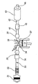
- FIG. 2 is a perspective view for explaining a fluid acceleration device according to the present invention.
- Figure 3 is a rear perspective view for explaining the fluid acceleration device according to the present invention.
- FIGS. 4 and 5 are cross-sectional views for explaining a fluid acceleration device according to the present invention.
- Figure 6 is a graph for explaining the loss coefficient for each type of inlet and outlet.
- FIG. 7 is a graph illustrating the loss coefficient according to the cabinet of the expanded discharge port.
- FIG. 8 is a plan view for explaining a fluid acceleration device according to the present invention.
- 9 and 10 are schematic diagrams for explaining the fluid acceleration device installed in the intake duct.
- FIG. 11 is an exploded perspective view for explaining another embodiment of the fluid acceleration device according to the present invention.
- FIG. 12 is a perspective view illustrating the fluid accelerator of FIG. 11.
- FIG. 13 is a plan view illustrating the fluid accelerator of FIG. 11.
- FIG. 14 is a side view illustrating the fluid accelerator of FIG. 12.
- FIG. 15 is a partial cutaway perspective view of the fluid accelerator of FIG. 12.
- FIG. 16 is a cross-sectional view illustrating the fluid accelerator of FIG. 12.
- fluid accelerator for the internal combustion engine
- Figure 2 is a perspective view for explaining a fluid acceleration device according to the present invention
- Figure 3 is a rear perspective view for explaining the fluid acceleration device according to the present invention.
- the fluid acceleration device includes a body 100 formed in a cylindrical structure, a center hole 200 formed in the center of the body 100, and the center hole 200.
- a plurality of middle holes 300 formed in the periphery of the body 100, and optionally a cover 400 surrounding the side of the body 100, and a support connecting the body 100 and the cover 400. 500 may further include.
- the fluid acceleration device is installed in an internal combustion engine such as a vehicle using a fluid such as air and fuel, and provides a function of improving a moving speed of a fluid flowing along a moving passage of the internal combustion engine.
- the present invention can also be applied to various kinds of machines and devices (cleaners, etc.) that need to speed up fluids in addition to internal combustion engines such as automobiles.
- the fluid acceleration device according to the present invention includes a body (100).
- the body 100 is formed in a cylindrical structure to be installed on the flow path of the fluid, and when used in the engine, between the cylinder head and the intake manifold, the inlet portion (before the surge tank), the intake filter and the intake manifold It can be selectively coupled according to the structure of the engine such as the end of the intake duct (intake) between the intake manifolds and the position immediately after passing through the intake filter.
- the intake means a pipe connecting the intake filter and the throttle body.
- FIGS. 4 and 5 are cross-sectional views for explaining a fluid acceleration device according to the present invention.
- an inflow groove 110 may be provided at an upper portion of the body 100 into which the fluid is introduced.
- the inlet groove 110 is formed in a gentle curve so that the fluid passing through the interior of the body 100 can be smoothly introduced into the center hole 200 and the middle hole 300, passing through the body 100 It provides a function to reduce the resistance generated when the fluid contacts the upper portion of the body (100).
- the inlet groove is formed to have a curved surface having an internal angle (b) of 30 to 60 of the body 100.
- the inlet groove according to the present invention is formed to have a curved surface having an internal angle of 60 at the tip, and then formed to have a curved surface having a gradually decreasing internal angle, and is formed to have a curved surface having an internal angle of 30 at the distal end.
- the inner angle b means an angle twice as large as the inner angle formed by the tangent of the central axis of the body 100 and the curved surface formed in the inflow groove.
- the inflow groove is provided with a plurality of inlet portions of the middle hole 300, and communicates with the inflow portion of the center hole 200.
- the lower surface of the body 100 that is, the rear end is preferably formed in a flat or round shape as shown in FIG.
- the body 100 is preferably formed to have a streamlined top and bottom cross-section of the outer peripheral surface to minimize the air resistance as shown in Figures 4 and 5.
- the body 100 is formed such that the central portion has an outer diameter longer than the upper and lower portions. This is to form a wide inlet and outlet of the side hole 450 formed through the cover 400 and the support 500, and to have a streamlined structure by forming a narrow passage between the inlet and the outlet than the inlet and outlet, the side The holes reduce the resistance caused by the vortex formed fluid.
- the fluid acceleration device according to the present invention includes a center hole 200.
- the center hole 200 forms a venturi passage in a vertical direction in the center of the body 100, and a spiral guide groove 240 is provided on an inner circumferential surface of the venturi passage, and passes through the venturi passage. It not only increases the flow rate of the fluid, but also provides the function of causing the fluid to rotate.
- the venturi passage is a passage having a wide cross-sectional area at both ends and narrowing toward the middle portion, so that when the air flows in the passage, the air is discharged at a higher speed by the pressure difference between the large cross section and the small portion. This change in fluid velocity is explained by Bernoulli's theorem.
- the air introduced into the center hole 200 is primarily formed through the venturi passage while the air pressure is changed by the venturi passage so that the air flow is formed very quickly, and at the same time, the spiral guide groove 240 formed in the inner wall is formed. Air rotates and flows.
- the center hole 200 is formed with a first inclined surface 220 having an inner angle (a) of 30 to 60 at the inlet portion in which the fluid is introduced.
- the inner angle (a) means an angle twice that of the inner angle formed by the tangent of the central axis of the body 100 and the curved surface formed in the inlet of the center hole.
- the first inclined surface 220 of the inflow portion is preferably formed in a curved surface.
- the center hole 200 is a second outlet having a fluid discharge portion is discharged to reduce the frictional resistance to the fluid at the outlet side 50% or less, preferably 15 to 50% of the inside angle (a) of the inlet It is preferable that the inclined surface 230 is formed. In other words, when the curved surface is formed at the inlet and outlet of the center hole 200, the wake resistance and friction are reduced.
- the outlet portion of the center hole 200 may have a second inclined surface 230 having an internal angle of 7.5 to 25. desirable.
- the inlet portion of the center hole 200 is formed with the first inclined surface 220 having an internal angle of 30
- the discharge portion of the center hole 200 is formed that the second inclined surface 230 having an internal angle of 4.5 to 15 is formed.
- frictional resistance is minimized as can be seen in FIG. 7 to be described later.
- Figure 6 is a graph for explaining the loss coefficient by type of inlet and outlet (Fluid mechanics. 7 / E, Frank M. White, McGraw-Hill publishing company, February 24, 2012)
- the inlet is formed as a protruding inlet as shown in (a) of Figure 6, or the inlet is formed with a sharp edge as in the case of the passage of the right cross-sectional shape of (b), the loss of the flow separation zone is increased.
- the inlet is formed in a curved surface as shown in the passage in the left cross-sectional view of Fig. 6B, the flow of the fluid is reduced and the loss is small.
- K in Figure 6 is the loss coefficient
- t is the thickness of the pipe
- d is the diameter of the pipe
- l is the length of the protruding pipe
- L is the length of the beveled edge
- r is the radius of curvature of the round portion Means.
- FIG. 7 is a graph for explaining the loss coefficient according to the cabinet of the expanded outlet (Fluid mechanics. 7 / E, published by Frank M. White, McGraw-Hill publishing company, February 24, 2012). As shown in FIG. 7, when the discharge portion through which the fluid is discharged is expanded, the loss factor K becomes about 0.16 at the lowest value at about 7.
- D 1 is the inlet diameter
- D 2 is the outlet diameter
- V 1 is the inlet speed
- V 2 is the outlet speed
- g the gravitational acceleration
- h L is the loss (loss head).
- the center hole 200 further increases the amount of air supplied to the engine, and not only changes the flow of air in a vortex according to the action of the spiral guide groove 240, Likewise, the rate of air flow into the engine is significantly increased.
- the center hole 200 increases the suction speed of the air to more finely split the water particles in the air, which is one of the incomplete combustion factors, and allows the fuel and air to be mixed more smoothly by the swirling air flow.
- the air compression ratio, heat of compression, and ignition point in the engine are increased, and the fuel mixture ratio is completely burned, thereby preventing the environmental pollution caused by soot, reducing fuel and increasing the engine output. to provide.
- the fluid acceleration device according to the present invention includes a middle hole 300.
- the middle hole 300 is formed in the up and down direction of the body 100 along the edge of the center hole 200 with respect to the center hole 200, and the air passing therethrough has a linear flow.
- the vortex state disappears due to the wall surface of the moving passage or the air passing through the side hole. And creates an air flow that serves as a guide for supplying the engine with the vortex type air stream passing through the center hole and the side hole, respectively, while maintaining the vortex.
- the sum of the cross-sectional areas of the plurality of middle holes 300 is preferably configured to be 1.1 to 1.5 times the minimum cross-sectional area of the center hole 200.
- the flow rate through the middle hole 300 compensates for the portion where the flow rate of the fluid passing through the center hole 200 changes according to the flow rate and pressure of the fluid generated at the front end of the center hole 200. It also plays a role. And the vortex phenomenon occurs in the rear end as the fluid flows through the center hole 200, the fluid passing through the middle hole 300 acts as an air curtain so that the flow rate of the fluid passing through the center hole 200 does not fall.
- the middle hole 300 is to compensate for the problem that the amount of fluid passing along the spiral guide groove 240 of the center hole 200 per unit time when the fluid flowing into the fluid accelerator is introduced at a low speed to compensate for the problem Provides the ability to In other words, since the middle hole 300 has a shorter moving path than the long center hole 200, the middle hole 300 passes the fluid flowing at a lower speed faster than the center hole 200, so that even if a strong pressure does not work. Provides a stable supply of fluid.
- the number of the middle holes 300 is not particularly limited because the number may be changed according to the size of the fluid accelerator, but it is preferable that 3 to 10 are formed in the body 100.
- the fluid acceleration device according to the present invention includes a cover 400.
- the cover 400 is provided to surround the side of the body 100 in a spaced apart state, as shown in FIG. 8, the side hole 450 on the outer side of the middle hole 300 together with the support 500. To form.
- the side hole 450 may be configured to prevent the fluid passing through the center hole 200 and the middle hole 300 from colliding with the inner surface of the pipe that provides the movement path of the fluid such as intake. Create a fluid that moves along. In other words, the side hole 450 reduces the frictional resistance that may be generated between the fluid passing through the center hole 200 and the middle hole 300 and the pipe by providing an air curtain effect on the inner surface of the pipe. Let's do it.
- cover 400 may be formed to have the same length as the length of the body 100 or longer than the length of the body 100 so that fluid flows smoothly into the side hole 450.
- the cover 400 has a wide inlet and outlet of the side hole 450 and the inflow of the side hole 450 when the outer peripheral surface of the body 100 has a streamlined structure in the vertical direction as shown in FIGS. It is preferable to have a constant inner diameter so that the passage connecting the part and the discharge part is narrowed. Due to this inclined structure, the speed of the air passing through the side hole 450 is increased.
- the fluid acceleration device according to the present invention includes a support 500.
- the support 500 is provided in the vertical direction of the body 100 between the body 100 and the cover 400 so that the cover 400 is fixed to the body 100, as shown in FIG.
- the side hole 450 is formed on the outer surface of the middle hole 300 together with the cover 400.
- the support 500 is a body in the vertical direction of the body 100 so that the fluid introduced through the side hole 450 formed between the cover 400 and the body 100 is discharged while rotating to form a vortex It is preferable to be provided in a curved shape to be twisted or inclined to the side of the (100). In this case, the support 500 forms a vortex in the fluid introduced into the side hole 450 to reduce the resistance acting on the fluid introduced into the side hole 450.
- the fluid acceleration device according to the present invention includes a ring flange 600.
- the ring flange 600 is provided along the outer circumferential surface of the cover 400, and provides a space in which the vermiculite ring 700 to be described later is seated on the outer circumferential surface of the cover 400. To this end, the ring flange 600 is preferably formed in the center portion of the cover 400.
- the outer diameter A1 of the fluid accelerator of the present invention is 70
- the flow rate V1 of the fluid is 6
- the inner diameter of the distal end of the center hole 200 is 22, and the inner diameters of the eight middle holes 300.
- the inner diameter of the cover 400 is 68
- the thickness of the side hole 450 is 3.5
- the width of the support 500 is 1
- the total cross-sectional area A2 of the outlet of the fluid accelerator and the Equation 1 for the flow rate (V2) of the fluid passing through the outlet is as follows.
- the fluid passing through the fluid accelerator increases at a speed of 2.54 times, and the inner diameter of the center hole 200 is increased.
- the fluid passing through the fluid accelerator is 2.31 times faster.
- the above-described formula is a formula that does not include the pressure / friction coefficient / viscosity of the fluid generated in the front end portion of the fluid accelerator, the flow rate of the fluid may vary depending on the pressure, friction coefficient or viscosity.
- FIGS. 9 and 10 are schematic views for explaining a fluid acceleration device installed in the intake duct
- Figure 11 is an exploded perspective view for explaining another embodiment of the fluid acceleration device according to the present invention.
- the fluid acceleration device according to the present invention may further include a vermiculite ring 700, vermiculite cap 800, or both.
- Such vermiculite ring 700 or vermiculite cap 800 may be provided in the fluid acceleration device installed in the internal combustion engine to move the suction air.
- FIG. 12 is a perspective view illustrating the fluid accelerator of FIG. 11,
- FIG. 13 is a plan view illustrating the fluid accelerator of FIG. 11,
- FIG. 14 is a side view illustrating the fluid accelerator of FIG. 12, and
- FIG. 15 is the fluid acceleration of FIG. 12.
- FIG. 16 is a cross-sectional view of the fluid accelerator of FIG. 12.
- the vermiculite ring 700 is mounted on the ring flange 600, is provided on the outer circumferential surface of the cover 400, and is composed of vermiculite, and is disposed on the outer circumferential surface of the cover 400. It may be configured to have an inner diameter corresponding to the outer diameter of the cover 400 to be seated on the ring flange 600 in a contact state. At this time, the vermiculite ring 700 may be manufactured by heating and compressing vermiculite with heat.
- vermiculite is a mineral belonging to a monoclinic system, and its chemical components are CMg, Fe 3+, and Al 3 (Al, Si) 4 O 10 (OH) 24 H 2 O, which are clay minerals of hydroxide silicate of aluminium magnesium iron.
- Vermiculite has firmness of 12, specific gravity of 2.76, off-white or brown, and pearlescent.
- vermiculite is easily decomposed into acids and has a large cation exchange capacity. When heated, it expands, is porous, and has good water absorption capability.
- the vermiculite ring 700 inserted into the intake duct while being fitted to the outer circumferential surface of the cover 400 absorbs moisture contained in the air sucked into the inlet of the fluid accelerator to have an outer diameter larger than the initial outer diameter.
- the fluid accelerator acts to be firmly coupled to the intake duct and also provides a sealing effect.
- the vermiculite cap 800 is provided at an upper portion of the body 100 into which fluid is introduced, and a through hole facing the center hole 200 and the middle hole 300 is formed. It is made of vermiculite, and is formed to have an outer shape corresponding to the inlet of the center hole 200 to be in close contact with the inlet of the center hole 200.
- the vermiculite cap 800 is moisture contained in the air sucked into the inlet of the fluid accelerator to reduce the water content contained in the fluid passing through the center hole 200, the middle hole 300 and the side hole 450 Provides the ability to absorb. As such, when the moisture in the air mixed with the fuel of the engine is reduced, fuel economy is improved and soot is reduced.
- Fluid accelerating device according to the present invention described above, as shown in Figures 9 and 10 so that the vermiculite ring 700 and the vermiculite cap 800 can be in smooth contact with the suction air, vermiculite ring 700 and vermiculite cap ( The upper portion of the fluid accelerator 10 in which 800 is installed is first inserted into the intake duct A.
- vermiculite ring 700 and vermiculite cap 800 absorbs the moisture contained in the intake air passing through the internal combustion engine as shown in FIG.
- c represents a fluid passing through the center hole 200
- m represents a fluid passing through the middle hole 300
- s represents a fluid passing through the side hole 450.
Landscapes
- Engineering & Computer Science (AREA)
- Chemical & Material Sciences (AREA)
- Combustion & Propulsion (AREA)
- Mechanical Engineering (AREA)
- General Engineering & Computer Science (AREA)
- Control Of Throttle Valves Provided In The Intake System Or In The Exhaust System (AREA)
- Exhaust Gas After Treatment (AREA)
Abstract
유체의 이동통로에 설치되어 유체의 이동속도를 개선시키는 유체가속장치가 개시된다. 이를 위하여 유체의 이동경로 상에 설치될 수 있도록 원통형 구조로 형성된 몸체와, 상기 몸체의 중앙에 상하 방향으로 벤투리 통로를 형성하며, 상기 벤투리 통로의 내주면에 나선형 가이드홈이 구비된 센터홀, 및 상기 센터홀의 중심으로 센터홀의 테두리를 따라 상기 몸체의 상하 방향으로 형성된 복수개의 미들홀을 포함하는 유체가속장치를 제공한다. 본 발명의 유체가속장치는 유체를 이용한 기존 장치에 간편하게 설치하여 유체의 속도를 향상시킬 수 있다.
Description
본 발명은 내연기관의 엔진에 공급되는 흡입 공기의 이동통로에 설치되는 내연기관용 유체가속장치에 관한 것으로, 보다 상세하게는 통과하는 공기의 유속을 향상시켜 줄 수 있도록 벤투리 구조가 적용된 내연기관용 유체가속장치에 관한 것이다.
일반적으로 내연기관 엔진의 4행정 구동을 살펴보면 흡입, 압축, 폭발, 배기의 순서로 작동하여 출력을 발생시키고 있다.
이러한 엔진 출력의 근원은 실린더 내의 연소실에서 발생하는 열에너지이다. 이때, 상기 연소실은 엔진의 헤드부에 있고 그 안에 밀폐되어 있는 미립화된 연료와 공기를 순간적으로 연소시켜 힘을 얻게 되는데, 출력을 높이기 위해서는 단위 시간에 발생하는 에너지가 증대되도록 더욱 많은 연료를 연소시켜야하며 이때는 보다 많은 흡입 공기량을 요구한다.
그러나 단순히 연소만 증대시켜서는 안 되고 확실한 고효율을 얻기 위해서는 여러 주변 조건을 맞춰주어야 한다.
상기 엔진 출력의 증대는 사용하는 공기의 양에 정비례하고 있으며 이러한 흡기의 양을 늘리기 위해서는 각 실린더의 배기량을 변경시키거나 공기의 흐름을 좋게 하거나 실린더의 수를 이용해서 이 양을 변화시키고 있다. 이때, 흡기 장치는 연소실에 필요한 공기를 공급해 주는 통로로서 엔진의 내구성을 증대시키는 매우 중요한 장치이다.
이러한 엔진의 4행정 구동 중에는 최초 흡입되는 공기의 입구와 배출되는 최종 배기구까지는 공기 흐름에 저항으로 작용하는 여러 복잡한 단계의 흡기압과 배기압이 발생된다.
최초 흡입구로부터 최종 배기구까지의 경로는 도 1에 도시된 바와 같이 흡기필터(31), 인테이크(32), 스로틀바디(33), 서지탱크(34), 흡기매니폴드(35), 헤드(흡기포트:36), 실린더 내 연소실(37), 헤드(배기포트:38), 배기매니폴드(39), 배기파이프(40), 촉매장치(41), 중간파이프(42), 메인소음기(43), 테일파이프(44)를 순차적으로 경유한다. 여기서, 인테이크는 흡기필터와 스로틀바디까지 연결하는 관을 의미한다.
크게 나누어보면 연소실을 기준으로 유입단에는 흡기압이, 배출단에는 배기압이 공기흐름에 대하여 저항으로 나타난다.
또한, 흡배기계통에서는 공기 흐름의 관성을 이용하여 충진 효율을 향상시키기 위해 흡기밸브와 배기밸브가 동시에 열려 있는 밸브 오버랩 시기가 있다.
상기 오버랩은 엔진의 회전속도에 따라 1초에 수십에서 백 수십 회 넘게 반복적으로 일어나고 밸브 오버랩 시기에는 흡기밸브의 기밀 유지 상태의 역할이 상실되어 역화의 원인을 제공하기도 한다. 이를 방지하기 위해 밸브 오버랩 기간을 두지 않는다면 공기의 관성 이용은 물론 피스톤의 상하 왕복운동에 상당한 공기압력의 기계적인 부하를 받게 되어 효율이 매우 낮아지는 모순에 의해 필연적으로 밸브 오버랩 시기를 설계할 수밖에 없다.
또한 흡기 맥동파는 흡기 행정 중 관성력에 의해 들어가는 공기가 흡입밸브의 닫힘에 의해 압력이 가해지면서 생겨 반대의 흐름을 발생시키며 들어오는 공기와 부딪혀 외부 공기의 유입은 방해를 받게 되고, 맥동파는 스로틀 바디 입구나 흡기필터(에어크리너 입구)까지 영향을 주게 되고 이러한 흡기 방해는 엔진 출력 저하의 원인 중 하나로 작용한다.
이러한 문제에 대응하기 위해 종래에도 다양한 형식의 기술이 제안되었다. 일반적으로는 토네이도, 싸이클론, 제트밸브, 터보차저, 수퍼차저, 인터쿨러 장치 등과 밸브 오버랩 시기의 가변적인 관성효과를 얻기 위한 캠샤프트가 알려져 있다.
이들은 흡입되는 공기를 보다 효율적인 관성효과로 유도하기 위한 수단과 강제 압력으로 유입되도록 하는 장치들이나 기대하는 만큼의 효과 달성이 어렵고, 밀도를 높여 공급하는 경우, 반대로 고밀도의 공기를 냉각시켜 주어야 하는 쿨러를 배치하는 등의 보완적인 장치 구성들로 인하여 매우 복잡하고 제조 원가가 증가되는 단점이 있다.
따라서, 본 발명의 목적은 내연기관에 유입되는 유체인 공기의 이동통로에 장착하여 흡입유체의 유속을 향상시키며 와류를 형성하되, 와류가 형성된 유체와 이동통로의 외벽의 마찰이 최소화되도록 유체의 이동을 조절할 수 있는 내연기관용 유체가속장치를 제공하는데 있다.
상술한 본 발명의 목적을 달성하기 위하여, 본 발명의 일 실시예에서는 유체의 이동경로 상에 설치될 수 있도록 원통형 구조로 형성된 몸체와, 상기 몸체의 중앙에 상하 방향으로 벤투리(venturi) 통로를 형성하며, 상기 벤투리 통로의 내주면에 나선형 가이드홈이 구비된 센터홀, 및 상기 센터홀의 중심으로 센터홀의 테두리를 따라 상기 몸체의 상하 방향으로 형성된 복수개의 미들홀을 포함하는 내연기관용 유체가속장치를 제공한다.
본 발명에 의한 유체가속장치는 유체를 이용한 기존 장치에 간편하게 설치하여 유체의 속도를 향상시킬 수 있다.
그리고 본 발명에 의한 유체가속장치를 내연기관의 엔진에 공급되는 공기의 통로에 장착하는 경우, 벤투리 구조 및 기타 기하학적 통로의 구조에 의해 흡입공기의 수분을 제거하고 유속을 증가시켜 연료와 공기의 혼합효율이 향상된다. 따라서 실린더 내의 공기 충진 비율이 개선되어 연료 절감의 효과가 나타나고 엔진의 연소성능을 향상시켜 줄 수 있다.
또한, 휘발유, 경유, LPG 등의 연료를 사용하는 내연기관에 공급되는 공기의 흐름에 와류를 발생시켜 연료와 공기가 소용돌이에 의하여 원활하게 혼합될 수 있다. 이에 따라 일정한 용량의 실린더 조건 내에서의 연소폭발반응속도를 높여 주게 되므로, 보다 높은 효율의 엔진 출력을 얻을 수 있으며 불완전연소에 따른 매연 등의 공해를 감소시킬 수 있다.
나아가, 본 발명은 인테이크(흡기덕트) 등의 차량 엔진에 연결된 내연기관에 사용되면, 차량의 고속주행이나 저속주행에 상관없이 인테이크 내에서 서지탱크의 역할, 즉 외부에 흡입된 후 필터를 통과한 공기를 일정하게 저장하여 엔진 작동 시에 일정한 압력으로 공기를 공급해 주는 역할을 한다. 다시 말해, 차량의 저속운행과 고속운행에 따라 엔진으로 공급되는 유체의 유량이 엔진 크랭크 회전수에 연관되어 공급되므로, 공기의 공급이 일정하지 않아 자동차 연료의 비중이 높고, 공기에 비중이 낮게 되어 완전 연소가 되지 않는 문제점이 있을 수 있다.
하지만, 본 발명에 의한 유체가속장치가 스로틀(throttle) 밸브 선단 및 흡기 덕트의 말단 사이에 조립되면 유체를 저장하는 서지(surge) 탱크의 역할을 하게 되고, 실린더 헤드의 작동이 있는 경우 유체가 엔진으로 일정하게 공급되도록 하는 효과를 나타낸다.
더욱이, 본 발명에 의한 유체가속장치는 흡기 매니폴드 전단부에 있는 서지탱크의 문제점을 개선할 수 있다.
구체적으로, 흡기 매니폴드 전단부에도 서지탱크가 있지만 차량이 고속일 때는 일정량의 공기가 서지탱크에서 흡기 매니폴드 쪽으로 공기를 공급해 주지만, 저속일 때는 서지탱크에 공기가 부족하여 흡기 매니폴드 각 라인으로 일정량에 공기를 공급하지 못한다. 이에 반해, 본 발명의 유체가속장치가 인테이크 내에 조립되면, 차량이 저속으로 운행하는 경우에도 서지탱크와 함께 유체가속장치가 공기를 저장하였다가 흡기 매니폴드로 공기를 보내주므로, 유체가속장치가 설치된 경우에는 차량의 운행 속도와 상관없이 흡기 매니폴드로 공기가 일정하게 공급될 수 있다.
도 1은 종래의 흡 배기장치를 포함하는 내연기관 엔진 구성도로서 밸브 오버랩 상태를 도시한 개략도이다.
도 2는 본 발명에 따른 유체가속장치를 설명하기 위한 사시도이다.
도 3은 본 발명에 따른 유체가속장치를 설명하기 위한 배면사시도이다.
도 4 및 도 5는 본 발명에 따른 유체가속장치를 설명하기 위한 단면도이다.
도 6은 유입구 및 배출구의 형태별 손실계수를 설명하기 위한 그래프이다.
도 7은 확장된 배출구의 내각에 따른 손실계수를 설명하기 위한 그래프이다.
도 8은 본 발명에 따른 유체가속장치를 설명하기 위한 평면도이다.
도 9 및 도 10은 흡기덕트에 설치되는 유체가속장치를 설명하기 위한 개략도이다.
도 11은 본 발명에 따른 유체가속장치의 다른 실시예를 설명하기 위한 분해사시도이다.
도 12는 도 11의 유체가속장치를 나타내는 사시도이다.
도 13은 도 11의 유체가속장치를 나타내는 평면도이다.
도 14는 도 12의 유체가속장치를 나타내는 측면도이다.
도 15는 도 12의 유체가속장치를 나타내는 부분 절단 사시도이다.
도 16은 도 12의 유체가속장치를 나타내는 단면도이다.
이하, 첨부도면을 참조하여 본 발명의 바람직한 실시 예들에 의한 내연기관용 유체가속장치(이하, '유체가속장치'라고 약칭함)를 상세하게 설명한다.
도 2는 본 발명에 따른 유체가속장치를 설명하기 위한 사시도이며, 도 3은 본 발명에 따른 유체가속장치를 설명하기 위한 배면사시도이다.
도 2 및 도 3을 참조하면, 본 발명에 따른 유체가속장치는 원통형 구조로 형성된 몸체(100)와, 상기 몸체(100)의 중앙에 형성된 센터홀(200), 및 상기 센터홀(200)의 주변의 몸체(100)에 형성된 복수개의 미들홀(300)을 포함하며, 선택적으로 몸체(100)의 측면을 둘러쌓는 커버(400), 및 상기 몸체(100)와 커버(400)를 연결하는 지지대(500)를 더 포함할 수 있다.
이러한 유체가속장치는 공기와 연료 등의 유체를 이용한 자동차 등의 내연기관에 설치되며, 상기 내연기관의 이동통로를 따라 흐르는 유체의 이동속도를 향상시켜 주는 기능을 제공한다. 또한, 자동차 등의 내연기관 이외에 유체의 속도를 빠르게 할 필요가 있는 각종 기계나 기구(청소기 등) 에도 적용할 수 있다.
이하, 도면을 참조하여 각 구성요소별로 보다 구체적으로 설명한다.
도 2 및 도 3을 참조하면, 본 발명에 따른 유체가속장치는 몸체(100)를 포함한다.
상기 몸체(100)는 유체의 이동경로 상에 설치될 수 있도록 원통형 구조로 형성된 것으로, 엔진에 사용되는 경우 실린더 헤드와 흡기 매니폴드 사이, 흡기 매니폴드의 입구부분(서지탱크 전), 흡기 필터와 흡기 매니폴드 사이의 흡기덕트(인테이크)의 말단, 흡기 필터를 거친 직후의 위치 등 엔진의 구조에 따라 선택적으로 결합할 수 있다. 여기서, 인테이크는 흡기필터와 스로틀바디를 연결하는 관을 의미한다.
도 4 및 도 5는 본 발명에 따른 유체가속장치를 설명하기 위한 단면도이다.
도 4를 참조하면, 유체가 유입되는 몸체(100)의 상부에는 유입홈부(110)가 구비될 수 있다. 이러한 유입홈부(110)는 몸체(100)의 내부를 통과하는 유체가 센터홀(200)과 미들홀(300)로 원활히 유입될 수 있도록 완만한 곡선 형태로 형성되어, 몸체(100)를 통과하는 유체가 몸체(100)의 상부에 접촉하는 경우 발생되는 저항을 줄여주는 기능을 제공한다.
이를 위해, 상기 유입홈부는 몸체(100)의 30 내지 60의 내각(b)을 갖는 곡면을 갖도록 형성된다. 특정 양태로서, 본 발명에 따른 유입홈부는 선단에 60의 내각을 갖는 곡면을 갖도록 형성되고, 이어서 점차 작아지는 내각을 갖는 곡면을 갖도록 형성되며, 말단에 30의 내각을 갖는 곡면을 갖도록 형성된다. 여기서, 내각(b)은 몸체(100)의 중심 축선과 상기 유입홈부에 형성된 곡면의 접선이 이루는 내각의 2배의 각을 의미한다.
또한, 상기 유입홈부는 복수개의 미들홀(300) 유입부가 구비되며, 센터홀(200)의 유입부와 연통된다.
아울러, 몸체(100)의 하면, 즉 후단은 도 3에 도시된 바와 같이 편평하거나 또는 라운드 형태로 형성되는 것이 바람직하다.
그리고 상기 몸체(100)는 도 4 및 도 5에 도시된 바와 같이 공기 저항을 최소화 할 수 있도록 외주면의 상하 단면이 유선형을 갖게 형성되는 것이 바람직하다. 이를 위해, 몸체(100)는 중앙부가 상부 및 하부보다 긴 외경을 갖도록 형성된다. 이는, 커버(400) 및 지지대(500)를 통해 형성된 사이드홀(450)의 유입구와 배출구를 넓게 형성하고, 유입구와 배출구 사이의 통로를 유입구 및 배출구보다 좁게 형성함으로써 유선형 구조를 갖도록 하여, 상기 사이드홀을 통해 와류가 형성된 유체에 의한 저항을 줄여준다.
도 2 및 도 3을 참조하면, 본 발명에 따른 유체가속장치는 센터홀(200)을 포함한다.
상기 센터홀(200)은 상기 몸체(100)의 중앙에 상하 방향으로 벤투리 통로를 형성하며, 상기 벤투리 통로의 내주면에 나선형 가이드홈(240)이 구비된 것으로, 상기 벤투리 통로를 통과하는 유체의 유속을 증가시킬 뿐만 아니라 유체가 회전되도록 하는 기능을 제공한다. 여기서, 벤투리 통로는 양끝은 넓은 단면적을 가지고 중간부로 갈수록 좁아지는 형태를 가진 통로로, 이러한 통로 내에 공기가 흐를 때 단면적이 큰 부분과 작은 부분간의 압력차에 의하여 공기가 보다 빠른 속도로 배출되도록 하는 부분이며, 이러한 유체 속도의 변화는 베르누이 정리에 의하여 설명된다.
다시 말해, 센터홀(200)로 유입된 공기는 1차적으로 벤투리 통로를 경유하면서 벤투리 통로에 의해 공기압이 변하여 공기의 흐름이 매우 빠르게 형성되고, 동시에 내벽에 형성된 나선형 가이드홈(240)에 의해 공기가 회전하여 유동한다.
구체적으로, 상기 센터홀(200)은 유체가 유입되는 유입부에 30 내지 60의 내각(a)을 갖는 제1 경사면(220)이 형성된다. 여기서, 내각(a)은 몸체(100)의 중심 축선과 상기 센터홀의 유입부에 형성된 곡면의 접선이 이루는 내각의 2배의 각을 의미한다.
이때, 센터홀(200)의 유입부가 날카로운 모서리로 되어 있거나 돌출되어 있으면 유동박리구역이 커져서 손실이 많아지므로, 상기 유입부의 제1 경사면(220)은 곡면으로 형성되는 것이 바람직하다.
또한, 상기 센터홀(200)은 출구쪽 유체에 대한 마찰저항을 줄이기 위해 유체가 배출되는 배출부가 상기 유입부의 내각(a)의 50%이하, 바람직하게는 15 내지 50%의 내각을 갖는 제2 경사면(230)을 갖도록 형성되는 것이 좋다. 다시 말해, 센터홀(200)의 유입부와 배출부에 곡면을 형성하게 되면 후류 저항 및 마찰이 줄어든다.
예컨대, 센터홀(200)의 유입부가 50의 내각을 갖는 제1 경사면(220)이 형성된 경우, 센터홀(200)의 배출부는 7.5 내지 25의 내각을 갖는 제2 경사면(230)이 형성되는 것이 바람직하다. 또한, 센터홀(200)의 유입부가 30의 내각을 갖는 제1 경사면(220)이 형성된 경우, 센터홀(200)의 배출부는 4.5 내지 15의 내각을 갖는 제2 경사면(230)이 형성되는 것이 바람직하여 이 경우, 후술하는 도 7에서 확인할 수 있는 바와 같이 마찰 저항이 최소화된다.
도 6은 유입구 및 배출구의 형태별 손실계수를 설명하기 위한 그래프이다(Fluid mechanics. 7/E, Frank M. White 저, McGraw-Hill 출판사, 2012.02.24.)
도 6의 (a)와 같이 돌출된 유입구가 형성되거나, (b)의 오른쪽 단면도 형상의 통로의 경우와 같이 유입구가 날카로운 모서리로 형성되어 있으면 유동박리구역이 커져서 손실이 증가된다. 이에 반해, 도 6의 (b)의 왼쪽 단면도 형상의 통로와 같이 유입구가 곡면으로 형성되어 있으면 유체의 유동에 도움이 되고 손실이 적어진다. 이때, 도 6에 기재된 K는 손실계수이고, t는 파이프의 두께이며, d는 파이프의 직경이고, l은 돌출된 파이프의 길이이며, L은 경사진 모서리의 길이이고, r은 라운드부의 곡률반경을 의미한다.
도 7은 확장된 배출구의 내각에 따른 손실계수를 설명하기 위한 그래프이다(Fluid mechanics. 7/E, Frank M. White 저, McGraw-Hill 출판사, 2012.02.24.). 도 7에 도시된 바와 같이, 유체가 배출되는 배출부가 확장된 경우, 가 약 7 정도에서 손실계수(K)는 약 0.16으로 최저가 된다. 이때, D1,은 입구측 직경, D2는 출구측 직경, V1는 입구측 속도, V2,는 출구측 속도, g는 중력가속도, hL은 손실량(손실수두)이다.
이와 같이, 센터홀(200)은 엔진으로 공급되는 공기의 량을 한층 더 증가시키고, 나선형 가이드홈(240)의 작용에 따라 소용돌이 형태(vortex)로 공기의 흐름을 변화시킬 뿐만 아니라, 후술하는 바와 같이 공기의 엔진으로의 유입속도를 현저하게 증가시킨다.
따라서, 센터홀(200)은 공기의 흡입속도를 증가시켜 불완전 연소 요인 중의 하나인 공기 내의 수분 입자를 보다 잘게 쪼개는 역할을 하고, 소용돌이 형태의 공기 흐름에 의하여 연료와 공기가 보다 원활하게 혼합되도록 하고, 엔진으로 많은 량의 공기를 공급하여 엔진 내의 공기압축비와 압축열, 착화점을 높여주고 연료 혼합비를 낮추어 연료를 완전 연소시키므로, 매연으로 인한 환경오염을 예방하고 연료 절감과 엔진의 출력을 높이는 효과가 제공한다.
도 2 및 도 3을 참조하면, 본 발명에 따른 유체가속장치는 미들홀(300)을 포함한다.
상기 미들홀(300)은 상기 센터홀(200)을 중심으로 센터홀(200)의 테두리를 따라 상기 몸체(100)의 상하 방향으로 형성되며, 이를 통과한 공기는 직선형의 흐름을 가지게 된다.
상기 센터홀(200)의 나선형 가이드홈(240)을 따라 형성된 와류가 센터홀(200)의 말단부를 통과한 후 이동통로의 벽면이나, 상기 사이드홀을 통과한 공기와 부딪혀서 와류상태가 소멸하는 것을 방지하고, 상기 센터홀과 사이드홀을 통과한 와류 형태의 공기 흐름이 각각 와류를 유지하면서 엔진으로 공급되도록 하는 가이드 역할을 하는 공기 흐름을 만들어 낸다.
여기서 복수개 미들홀(300)의 단면적의 총합은 센터홀(200) 최소 단면적의 1.1 내지 1.5배로 구성하는 것이 바람직하다. 이러한 미들홀(300)을 통과하는 유량은 센터홀(200)의 전단부에서 발생하는 유체의 유속 및 압력에 따라 센터홀(200)을 통과하는 유체의 유속이 변화를 발생하는 부분을 보완하여 주는 역할도 한다. 그리고 센터홀(200)에 유체가 흐르면서 후단부에 와류 현상이 발생 하는데, 미들홀(300)을 통과하는 유체가 에어 커튼 역할을 하여 센터홀(200)을 통과한 유체의 유속이 떨어지지 않게 한다.
또한, 미들홀(300)은 유체가속장치로 유입되는 유체가 저속으로 유입되는 경우, 단위 시간 당 센터홀(200)의 나선형 가이드홈(240)을 따라 통과하는 유체량이 부족해 질 수 있는 문제점을 보완하는 기능을 제공한다. 다시 말해, 미들홀(300)은 유체의 이동경로가 긴 센터홀(200)보다 짧은 이동경로를 가지고 있기 때문에 저속으로 유입되는 유체를 센터홀(200)보다 빠르게 통과시키므로, 강한 압력이 작용하지 않더라도 유체를 안정적으로 공급하는 기능을 제공한다.
이러한 미들홀(300)은 개수는 유체가속장치의 크기에 따라 변경될 수 있으므로 특별히 한정되지 않지만, 3 내지 10개가 몸체(100)에 형성되는 것이 바람직하다.
도 2 및 도 3을 참조하면, 본 발명에 따른 유체가속장치는 커버(400)를 포함한다.
상기 커버(400)는 상기 몸체(100)의 측면을 이격된 상태로 감싸도록 구비된 것으로, 도 8에 도시된 바와 같이 지지대(500)와 함께 미들홀(300)의 외각에 사이드홀(450)을 형성한다.
이러한 사이드홀(450)은 센터홀(200) 및 미들홀(300)을 통과한 유체가 인테이크 등 유체의 이동경로를 제공하는 파이프의 내측면에 부딪히는 현상을 억지할 수 있도록 상기 파이프의 내측면을 따라 이동하는 유체를 생성한다. 다시 말해, 사이드홀(450)은 상기 파이프의 내측면에 대한 에어커튼 효과를 제공함으로써 센터홀(200) 및 미들홀(300)을 통과한 유체와 상기 파이프 사이에 발생될 수 있는 마찰 저항을 축소시킨다.
그리고 커버(400)는 상기 사이드홀(450)로 유체가 원활히 유입될 수 있도록 몸체(100)의 길이와 동일한 길이로 형성되거나 몸체(100)의 길이보다 긴 길이로 형성되는 것이 바람직하다.
또한, 상기 커버(400)는 몸체(100)의 외주면이 도 4 및 도 5와 같이 상하방향으로 유선형 구조를 갖는 경우에 사이드홀(450)의 유입부와 배출부가 넓고 사이드홀(450)의 유입부와 배출부를 연결하는 통로가 좁아지도록 일정한 내경을 갖게 형성되는 것이 바람직하다. 이러한 경사진 구조에 의하여 상기 사이드홀(450)을 통과하는 공기의 속도는 빨라지게 된다.
도 2 및 도 3을 참조하면, 본 발명에 따른 유체가속장치는 지지대(500)를 포함한다.
상기 지지대(500)는 상기 커버(400)가 몸체(100)에 고정되도록 몸체(100)와 커버(400) 사이에 몸체(100)의 상하 방향으로 구비된 것으로, 도 8에 도시된 바와 같이 상기 커버(400)와 함께 미들홀(300)의 외각에 사이드홀(450)을 형성한다.
상기 지지대(500)는 상기 커버(400)와 몸체(100)의 사이에 형성된 사이드홀(450)을 통해 유입된 유체가 회전하면서 배출되어 와류를 형성할 수 있도록 몸체(100)의 상하방향으로 몸체(100)의 측면에 비틀어지게 또는 기울어지게 커브형으로 구비되는 것이 바람직하다. 이때, 지지대(500)는 사이드홀(450)로 유입된 유체에 와류를 형성함으로써 사이드홀(450)로 유입된 유체에 작용하는 저항을 줄여준다.
도 2 및 도 3을 참조하면, 본 발명에 따른 유체가속장치는 링 플랜지(600)를 포함한다.
상기 링 플랜지(600)는 상기 커버(400)의 외주면을 따라 구비된 것으로, 후술하는 질석링(700)이 커버(400)의 외주면에 안착될 수 있는 공간을 제공한다. 이를 위해, 링 플랜지(600)는 커버(400)의 가운데 부분에 형성되는 것이 바람직하다.
여기서, 앞서 설명한 구조의 본 발명에 따른 유체가속장치를 사용하는 경우, 공기의 유입부에 비하여 배출구 속도가 어느 정도 빨라지는 지 베르누이 방정식을 사용하여 계산하여 보면 다음과 같다.
예를 들어, 본 발명의 유체가속장치의 외경(A1)이 70이고, 유체의 유속(V1)이 6이며, 센터홀(200) 말단부의 내경이 22이고, 8개 미들홀(300)의 내경이 각각 8.5이며, 커버(400)의 내경이 68이고, 사이드홀(450)의 두께가 3.5이며, 지지대(500)의 너비가 1인 경우, 유체가속장치의 배출구의 총 단면적(A2)과 상기 배출구를 통과하는 유체의 유속(V2)에 대한 [수학식 1]은 아래와 같다.
수학식 1 


또한, 다른 조건이 동일하고 센터홀(200) 말단부의 내경이 26인 경우, 유체가속장치의 배출구의 총 단면적(A2)과 상기 배출구를 통과하는 유체의 유속(V2)에 대한 [수학식 2]는 아래와 같다.
수학식 2 


이와 같이, 유체가속장치의 전단부에 6로 유체가 유입되고 센터홀(200)의 내경이 22이면 유체가속장치를 통과하는 유체는 2.54배의 속도가 상승하며, 센터홀(200)의 내경이 26이면 유체가속장치를 통과하는 유체는 2.31배의 속도가 상승한다. 이때, 전술한 계산식은 유체가속장치의 전단부에 발생하는 유체의 압력/마찰계수/점도를 포함하지 않는 계산식이며, 압력이나 마찰계수 또는 점도 등에 따라 유체의 유속이 달라질 수 있다.
도 9 및 도 10은 흡기덕트에 설치되는 유체가속장치를 설명하기 위한 개략도이며, 도 11은 본 발명에 따른 유체가속장치의 다른 실시예를 설명하기 위한 분해사시도이다.
도 9 내지 도 11을 참조하면, 본 발명에 따른 유체가속장치는 질석링(700), 질석캡(800), 또는 이들 모두를 더 포함할 수 있다.
이러한 질석링(700)이나 질석캡(800)은 흡입공기가 이동하는 내연기관에 설치된 유체가속장치에 구비될 수 있다.
도 12는 도 11의 유체가속장치를 나타내는 사시도이고, 도 13은 도 11의 유체가속장치를 나타내는 평면도이며, 도 14는 도 12의 유체가속장치를 나타내는 측면도이고, 도 15는 도 12의 유체가속장치를 나타내는 부분 절단 사시도이며, 도 16은 도 12의 유체가속장치를 나타내는 단면도이다.
도 9 내지 도 16을 참조하면, 상기 질석링(700)은 상기 링 플랜지(600)에 안착되고 상기 커버(400)의 외주면에 구비되며 질석(vermiculite)으로 구성된 것으로, 커버(400)의 외주면에 접촉된 상태로 링 플랜지(600)에 안착될 수 있도록 커버(400)의 외경에 대응되는 내경을 갖도록 구성될 수 있다. 이때, 질석링(700)은 질석을 열로 가열하고 압축하여 제조할 수 있다.
이러한 질석은 단사정계(單斜晶系)에 속하는 광물로, 화학성분은 CMg, Fe3+, Al3(Al,Si)4O10(OH)24H2O이며, 알루미마그네슘철의 수산화규산염으로 된 점토광물이다. 그리고 질석은 굳기가 12이며, 비중 2.76이고, 회백색 또는 갈색이며, 진주광택이 난다. 또한, 질석은 산(酸)에 쉽게 분해되고, 양이온 교환능력이 크며. 가열하면 팽창하고, 다공질(多孔質)이며, 수분 등의 흡수능력이 좋다.
또한, 커버(400)의 외주면에 끼움결합된 상태로 흡기덕트의 내부에 내삽된 질석링(700)은 유체가속장치의 유입부로 흡입되는 공기에 포함된 수분을 흡수하여 초기 외경보다 큰 외경을 갖도록 팽창되므로, 유체가속장치가 흡기덕트에 견고히 결합될 수 있도록 작용하며 실링효과도 제공한다.
도 9 내지 도 16을 참조하면, 상기 질석캡(800)은 유체가 유입되는 몸체(100)의 상부에 구비되고, 상기 센터홀(200)과 미들홀(300)에 마주보는 관통홀이 형성되며, 질석으로 구성된 것으로, 센터홀(200)의 유입부에 밀착될 수 있도록 센터홀(200)의 유입부에 대응되는 외형을 갖도록 형성된다.
이러한 질석캡(800)은 센터홀(200)과 미들홀(300) 및 사이드홀(450)을 통과하는 유체에 포함된 수분함량이 줄어들 수 있도록 유체가속장치의 유입부로 흡입되는 공기에 포함된 수분을 흡수하는 기능을 제공한다. 이와 같이, 엔진의 연료와 혼합되는 공기의 수분이 줄어들면 연비가 향상되고 매연이 감소된다.
전술한 본 발명에 따른 유체가속장치는 질석링(700)과 질석캡(800)이 흡입공기와 원활히 접촉될 수 있도록 도 9 및 도 10에 도시된 바와 같이, 질석링(700)과 질석캡(800)이 설치된 유체가속장치(10)의 상부가 먼저 흡기덕트(A)의 내부에 내삽된다.
그리고 질석링(700)과 질석캡(800)은 도 10에 도시된 바와 같이 내연기관을 통과하는 흡입공기에 포함된 수분을 흡수한다. 이때, c는 센터홀(200)을 통과한 유체를 나타내고, m은 미들홀(300)을 통과한 유체를 나타내며, s는 사이드홀(450)을 통과한 유체를 나타낸다.
이상에서 본 발명의 바람직한 실시예를 참조하여 설명하였지만, 해당 기술분야의 숙련된 당업자는 하기의 특허청구범위에 기재된 본 발명의 사상 및 영역으로부터 벗어나지 않는 범위 내에서 본 발명을 다양하게 수정 및 변경시킬 수 있음을 이해할 수 있을 것이다.
Claims (8)
- 유체의 이동경로 상에 설치될 수 있도록 원통형 구조로 형성된 몸체;상기 몸체의 중앙에 상하 방향으로 벤투리 통로를 형성하며, 상기 벤투리 통로의 내주면에 나선형 가이드홈이 구비된 센터홀; 및상기 센터홀의 중심으로 센터홀의 테두리를 따라 상기 몸체의 상하 방향으로 형성된 복수개의 미들홀을 포함하는 유체가속장치.
- 제1 항에 있어서, 상기 센터홀은상기 유체가 유입되는 유입부에 30 내지 60의 제1 경사면이 형성되며, 상기 유체가 배출되는 배출부에 상기 유입부의 15 내지 50%의 내각을 갖는 제2 경사면이 형성된 것을 특징으로 하는 유체가속장치.
- 제2 항에 있어서, 상기 유입부의 제1 경사면은 곡면인 것을 특징으로 하는 유체가속장치.
- 제1 항에 있어서,상기 몸체의 측면 이격된 상태로 감싸도록 구비된 커버; 및상기 커버가 몸체에 고정되도록 몸체와 커버 사이에 몸체의 상하 방향으로 구비된 지지대를 더 포함하는 유체가속장치.
- 제4 항에 있어서, 상기 몸체는중부가 상부 및 하부보다 긴 외경을 갖도록 형성된 것을 특징으로 하는 유체가속장치.
- 제4 항에 있어서, 상기 지지대는상기 커버와 몸체의 사이에 형성된 사이드홀을 통해 유입된 유체가 회전하면서 배출될 수 있도록 몸체의 상하방향으로 몸체의 측면에 기울어지게 커브형으로 구비된 것을 특징으로 하는 유체가속장치.
- 제4 항에 있어서,상기 커버의 외주면을 따라 구비된 링 플랜지; 및상기 링 플랜지에 안착되고 상기 커버의 외주면에 구비되며 질석으로 구성된 질석링을 더 포함하는 것을 특징으로 하는 유체가속장치.
- 제1 항에 있어서,상기 유체가 유입되는 상기 몸체의 상부에 구비되며, 상기 센터홀과 미들홀에 마주보는 관통홀이 형성된 질석캡을 더 포함하는 것을 유체가속장치.
Priority Applications (4)
| Application Number | Priority Date | Filing Date | Title |
|---|---|---|---|
| JP2018505743A JP2019520507A (ja) | 2016-03-30 | 2016-09-13 | 内燃機関用流体加速装置 |
| CN201680046375.9A CN107850017A (zh) | 2016-03-30 | 2016-09-13 | 内燃机用流体加速装置 |
| EP16897180.2A EP3438441A4 (en) | 2016-03-30 | 2016-09-13 | LIQUID ACCELERATOR FOR A COMBUSTION ENGINE |
| US15/749,002 US20190085800A1 (en) | 2016-03-30 | 2016-09-13 | Fluid accelerator for internal combustion enginge |
Applications Claiming Priority (2)
| Application Number | Priority Date | Filing Date | Title |
|---|---|---|---|
| KR1020160038267A KR101794524B1 (ko) | 2016-03-30 | 2016-03-30 | 내연기관용 유체가속장치 |
| KR10-2016-0038267 | 2016-03-30 |
Publications (1)
| Publication Number | Publication Date |
|---|---|
| WO2017171159A1 true WO2017171159A1 (ko) | 2017-10-05 |
Family
ID=59964841
Family Applications (1)
| Application Number | Title | Priority Date | Filing Date |
|---|---|---|---|
| PCT/KR2016/010312 Ceased WO2017171159A1 (ko) | 2016-03-30 | 2016-09-13 | 내연기관용 유체가속장치 |
Country Status (6)
| Country | Link |
|---|---|
| US (1) | US20190085800A1 (ko) |
| EP (1) | EP3438441A4 (ko) |
| JP (1) | JP2019520507A (ko) |
| KR (1) | KR101794524B1 (ko) |
| CN (1) | CN107850017A (ko) |
| WO (1) | WO2017171159A1 (ko) |
Families Citing this family (11)
| Publication number | Priority date | Publication date | Assignee | Title |
|---|---|---|---|---|
| WO2019203437A1 (ko) * | 2018-04-17 | 2019-10-24 | 주식회사 아스티즈 | 내연기관의 출력 증강을 위한 소음 저감형 흡기장치 |
| KR101956780B1 (ko) * | 2018-08-20 | 2019-03-12 | 백효성 | 내연기관용 와류기 |
| CN110896434A (zh) * | 2018-09-13 | 2020-03-20 | 宝山钢铁股份有限公司 | 一种提高智能扒渣摄像头成像质量的气幕系统 |
| KR102100624B1 (ko) * | 2018-11-23 | 2020-04-14 | 유병남 | 내연 기관용으로 유체의 유속 변경이 가능한 유체가속 장치 |
| KR102055547B1 (ko) * | 2019-05-27 | 2019-12-13 | 임현빈 | 엔진출력 증폭기 |
| US11193598B2 (en) | 2019-09-25 | 2021-12-07 | Control Components, Inc. | Low shear ball-type control valve |
| KR102232248B1 (ko) * | 2020-04-27 | 2021-03-24 | 홍금표 | 내연기관용 매연저감장치 |
| JP7384120B2 (ja) * | 2020-06-23 | 2023-11-21 | トヨタ紡織株式会社 | プリクリーナ |
| CN112742273B (zh) * | 2020-12-30 | 2021-07-09 | 乐匀(南通)机电混合设备有限公司 | 一种在线真空高速溶粉机 |
| WO2024127676A1 (ja) * | 2022-12-16 | 2024-06-20 | 正鎬 金 | 燃焼効率等向上装置およびアタッチメントならびに方法 |
| WO2025068808A1 (en) * | 2023-09-29 | 2025-04-03 | Luxnara Yaovaphankul | An apparatus for creating forced vortex |
Citations (5)
| Publication number | Priority date | Publication date | Assignee | Title |
|---|---|---|---|---|
| KR19990075276A (ko) * | 1998-03-18 | 1999-10-15 | 이영성 | 차량 엔진에서의 흡입공기 유동성 증대장치 |
| KR20010112571A (ko) * | 2000-06-09 | 2001-12-20 | 이범수 | 차량용 흡기매니폴드 |
| US20140338781A1 (en) * | 2013-05-20 | 2014-11-20 | Steere Enterprises, Inc | Swirl vane air duct cuff assembly and method of manufacture |
| KR20150118463A (ko) * | 2014-04-14 | 2015-10-22 | 박상호 | 공기 흐름 개선 증폭장치 |
| KR20150118451A (ko) * | 2014-04-14 | 2015-10-22 | 박상호 | 에어 증폭장치 |
Family Cites Families (23)
| Publication number | Priority date | Publication date | Assignee | Title |
|---|---|---|---|---|
| US1639396A (en) * | 1925-02-21 | 1927-08-16 | Carlsson Carl | Carburetor for internal-combustion engines |
| US2017043A (en) * | 1930-09-17 | 1935-10-15 | Galliot Norbert | Device for conveying gaseous streams |
| US3774645A (en) * | 1971-12-06 | 1973-11-27 | Universal Oil Prod Co | Flange-free venturi nozzle insert |
| FR2265997A1 (ko) * | 1974-03-29 | 1975-10-24 | Reissmueller Anton | |
| US4092966A (en) * | 1976-11-03 | 1978-06-06 | Vortac, Inc. | Fuel vaporizing and mixing device for gasoline engines |
| US4208136A (en) * | 1978-12-01 | 1980-06-17 | Komax Systems, Inc. | Static mixing apparatus |
| US4303143A (en) * | 1980-01-28 | 1981-12-01 | Mitsuko Leith | Exhaust gas control system |
| JP3432460B2 (ja) * | 1999-08-10 | 2003-08-04 | 株式会社アメニティ | 流量調節具 |
| US7534401B2 (en) * | 2001-03-16 | 2009-05-19 | Global Environmental Concepts, Llc | Arcing electron stream apparatus and method |
| CN2576987Y (zh) * | 2002-10-28 | 2003-10-01 | 孟启平 | 发动机进气文氏管装置 |
| US6928979B2 (en) * | 2003-11-10 | 2005-08-16 | Jung-Pin Cho | Gas-economizing powerful engine speed increaser |
| CA2455485A1 (en) * | 2004-01-21 | 2005-07-21 | Lt Exhaust Systems Inc. | Anti-reversion apparatus |
| JP3105220U (ja) * | 2004-05-13 | 2004-10-21 | 洋一 竹垣 | スパイラルファンネル |
| US20110232604A1 (en) * | 2005-12-12 | 2011-09-29 | Global Sustainability Technologies L.L.C. | Device for enhancing fuel efficiency and reducing emissions of internal combustion engines |
| TW200743727A (en) * | 2006-05-17 | 2007-12-01 | zhong-yu Yang | Air intake enhancer for engine |
| JP2007315343A (ja) * | 2006-05-29 | 2007-12-06 | Kazuyuki Masago | 内燃機関における吸気装置及び吸気方法 |
| US7267098B1 (en) * | 2006-08-19 | 2007-09-11 | Addy Tasanont | Vortex generating air intake device |
| US7552723B1 (en) * | 2008-05-20 | 2009-06-30 | Hector Ugalde | Turbine assembly |
| US20100031920A1 (en) * | 2008-08-07 | 2010-02-11 | Chien Chang-Ho | Air Intake Device |
| US8220444B2 (en) * | 2009-05-27 | 2012-07-17 | Mackson Limited | System for improving the efficiency of an internal combustion engine of a vehicle |
| US7954514B2 (en) * | 2009-09-30 | 2011-06-07 | Chun-Shuo Tung | Air-admitting guide member |
| IN2013MU02552A (ko) * | 2013-08-02 | 2015-06-12 | Deere & Co | |
| KR101578840B1 (ko) * | 2014-04-14 | 2015-12-23 | (주)에이씨씨기술 | 내연기관의 연소효율 향상장치 |
-
2016
- 2016-03-30 KR KR1020160038267A patent/KR101794524B1/ko not_active Expired - Fee Related
- 2016-09-13 WO PCT/KR2016/010312 patent/WO2017171159A1/ko not_active Ceased
- 2016-09-13 CN CN201680046375.9A patent/CN107850017A/zh active Pending
- 2016-09-13 EP EP16897180.2A patent/EP3438441A4/en not_active Withdrawn
- 2016-09-13 JP JP2018505743A patent/JP2019520507A/ja active Pending
- 2016-09-13 US US15/749,002 patent/US20190085800A1/en not_active Abandoned
Patent Citations (5)
| Publication number | Priority date | Publication date | Assignee | Title |
|---|---|---|---|---|
| KR19990075276A (ko) * | 1998-03-18 | 1999-10-15 | 이영성 | 차량 엔진에서의 흡입공기 유동성 증대장치 |
| KR20010112571A (ko) * | 2000-06-09 | 2001-12-20 | 이범수 | 차량용 흡기매니폴드 |
| US20140338781A1 (en) * | 2013-05-20 | 2014-11-20 | Steere Enterprises, Inc | Swirl vane air duct cuff assembly and method of manufacture |
| KR20150118463A (ko) * | 2014-04-14 | 2015-10-22 | 박상호 | 공기 흐름 개선 증폭장치 |
| KR20150118451A (ko) * | 2014-04-14 | 2015-10-22 | 박상호 | 에어 증폭장치 |
Non-Patent Citations (1)
| Title |
|---|
| See also references of EP3438441A4 * |
Also Published As
| Publication number | Publication date |
|---|---|
| KR20170111940A (ko) | 2017-10-12 |
| EP3438441A1 (en) | 2019-02-06 |
| JP2019520507A (ja) | 2019-07-18 |
| US20190085800A1 (en) | 2019-03-21 |
| CN107850017A (zh) | 2018-03-27 |
| EP3438441A4 (en) | 2019-12-04 |
| KR101794524B1 (ko) | 2017-11-07 |
Similar Documents
| Publication | Publication Date | Title |
|---|---|---|
| WO2017171159A1 (ko) | 내연기관용 유체가속장치 | |
| US6016655A (en) | Apparatus for improving intake charge vaporization and induction for an internal combustion engine | |
| GB2180594A (en) | Intake manifold system | |
| ATE282770T1 (de) | Vorrichtung zum transfer von auspuffgasen vom auslassammelrohr einer brennkraftmaschine zum einlasskanal | |
| JPS5947128B2 (ja) | 内燃機関の吸気装置 | |
| SE450720B (sv) | Sett att driva forbrenningsmotorer med avgasatercirkulation | |
| WO2010117127A2 (en) | Solenoid permanent magnet engine | |
| GB2058906A (en) | Intake system for an internal combustion engine | |
| WO2017082481A1 (ko) | 인터쿨러 및 인터쿨러의 응축수 배출 장치 | |
| US7367329B2 (en) | Intake device for engine | |
| CN113107661A (zh) | 一种分层扫气二冲程发动机 | |
| CN218882395U (zh) | 一种具有对置式氢气气道喷射的氢单缸发动机装置 | |
| JPS5813122A (ja) | 内燃機関における吸排気の渦流発生装置 | |
| KR102011888B1 (ko) | 내연기관용 유체흐름 조절장치 및 이를 포함하는 체크밸브 | |
| JP3799183B2 (ja) | エンジンの吸気装置 | |
| DE3477232D1 (en) | Arrangement for introducing additional gas streams to the intake manifold of a fuel-air mixture compression internal-combustion engine | |
| CN217976401U (zh) | 发动机气缸盖罩及车辆 | |
| JP3094215B2 (ja) | エンジンの吸気装置 | |
| SU1348544A1 (ru) | Устройство дл наддува двигател внутреннего сгорани | |
| KR200321339Y1 (ko) | 디젤엔진용 흡기관 | |
| KR19990031721U (ko) | 자동차 흡기관의 구조 | |
| CN2908828Y (zh) | 翻滚式气旋涡流生成器 | |
| CN121782074A (zh) | 一种可变通道的发动机进气系统及二冲程发动机 | |
| JP2000329038A (ja) | エンジンの吸気装置 | |
| JP4288032B2 (ja) | 2サイクルエンジン |
Legal Events
| Date | Code | Title | Description |
|---|---|---|---|
| ENP | Entry into the national phase |
Ref document number: 2018505743 Country of ref document: JP Kind code of ref document: A |
|
| NENP | Non-entry into the national phase |
Ref country code: DE |
|
| 121 | Ep: the epo has been informed by wipo that ep was designated in this application |
Ref document number: 16897180 Country of ref document: EP Kind code of ref document: A1 |